

Recomendados
Recomendados
Mais conteúdo relacionado
Mais procurados
Mais procurados (7)
Destaque
Destaque (19)
Semelhante a 85 0079 vds insert
Semelhante a 85 0079 vds insert (20)
Mais de Accurate Pool & Spa Services, llc
Mais de Accurate Pool & Spa Services, llc (20)
85 0079 vds insert
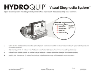
- 1. Visual Diagnostic System Hydro-Quip designed the Visual Diagnostic System to offer a simple on-site diagnosis capability to our customers. Air Sw itche Pump s 1 VDSf Visual Diagnostic Systemf TIMER EM ST p2 Y Pum S ) ional (Opt Light Air TER HEA ON e Ozon ER Aux. POWTROL CON Switch on ional ) I or u Man peration o and dures ati GFC to Oper ing r t Refe al for tes l a 2 (Opt Aux. System Mis-Wire If a VDS light is proc e 11 , Time tratio n d Fil d Filtrati on (Opt ional) imed Heat Heat, Time 1 - T ermosta 2-T h t illuminated, refer to Owners Manual for High-Limit Tripped details e mf Syst stic gno l Dia fV isua VDS VDS t is ligh fer to , re If a inated ual fo illumers Ma n r Pump/Air Fuse re -W i Ownils Mis deta tem Sys ipp ed t Tr imi h-L Hig se RHE AT OVE ECTIO N PROTReset ion to at Push to Oper ils Pum p/A ir Fu y Fu se (Opt .) Auxiliary Fuse (Opt.) r Refe al for de ta liar M an u Auxi ! System Mis-Wire - lets the electrician know that a Line voltage wire has been connected to the Neutral wire connection (the system will not operate until this has been corrected). ! High-Limit Tripped - lets the end-user know that there is an overheat condition (consult your Owners manual for specific details). ! Pump/Air Fuse - indicates just that, the Pump/Air fuse has blown (call a qualified technician to investigate and correct the problem). ! Auxiliary Fuse - indicates that the auxiliary fuse has blown (call a qualified technician to investigate and correct the problem). 850079 Rev.0 04.03 http://www.MyPoolSpas.com Wholesale Pool and Spa Parts 920-925-3094
- 2. Visual Diagnostic System VDSf Visual Diagnostic Systemf 1 Pump 2 Pump Light ona l) (Opti Air ne Ozo R POWEROL T CON CH ion SWrIT Operating to t es Refe al for t al Pum p3 System Fuse u Man peratio o and edures proc n O Circ . If a VDS light is stic Syste mf P T I . illuminated, refer to gno O Aux f Visu al Dia N A Owners Manual for VDS ght is o DS li refer If a Vinated, al for illumers Man u t L Aux . High Limit Tripped details Own ls Fuse deta i te m Sys ped Trip mit h Li Hig se Pu mp 1 Fu r Fu se TAT E Pump 1 Fuse ID-S EM owe TER Bl HEA SOLL SYST Air ON e Fus TRO p2 Pum Pum p3 Fus e CON se Circ. Pum p Fu se Air Blower Fuse e Fu Ozon Pump 2 Fuse Pump 3 Fuse Circ. Pump/Ozone Fuse ! System Mis-Wire - lets the electrician know that a Line voltage wire has been connected to the Neutral wire connection (the system will not operate until this has been corrected). ! High-Limit Tripped - lets the end-user know that there is an overheat condition (consult your Owners manual for specific details). ! Pump 1 Fuse - indicates just that, the primary pump fuse has blown (call a qualified technician to investigate and correct the problem). ! Air Blower Fuse - indicates just that, the air blower fuse has blown (call a qualified technician to investigate and correct the problem). ! * Pump 2 Fuse - indicates that the secondary pump fuse has blown (call a qualified technician to investigate and correct the problem). ! * Pump 3 Fuse - indicates that the secondary pump fuse has blown (call a qualified technician to investigate and correct the problem). ! * Cir. Pump/Ozone Fuse - indicates that the circulation pump fuse has blown (call a qualified technician to investigate and correct the problem). *Indicates optional circuits that may or may not be included in your particular control system. http://www.MyPoolSpas.com Wholesale Pool and Spa Parts 920-925-3094