SlideShare uma empresa Scribd logo
1 de 18
Baixar para ler offline
Proprietary and Confidential
ReGenX Generator and ReGen-X Motor
Demonstration Protocols
McMaster and Waterloo University EV
Regenerative Acceleration Innovation
Demonstrations
Prepared by Thane C. Heins
ReGenXtra Co-founder and CTO
February 20th, 2017
This document outlines the demonstration protocols which will be used to demonstrate
and explain the operation of the ReGenX Regenerative Acceleration Generator
and the ReGen-X Regenerative Acceleration Motor prototype innovations.
Proprietary and Confidential
2
Table of Contents
1.0 Primary Area of Research & Development.............................................................................................3
1.1 ReGenX Generator and ReGen-X Motor.............................................................................................3
2.0 ReGenX Generator Demonstration Protocol Prototype No. 1...............................................................4
2.1 Demonstration Initiation.....................................................................................................................5
3.0 ReGenX Generator Demonstration Protocol Prototype No. 2...............................................................7
3.1 Demonstration Initiation.....................................................................................................................7
3.2 Operating Prototype No. 2 Below the ReGenX Generator Coil’s Critical Minimum Frequency.........8
4.0 Factors that Dictate the ReGenX Generator Coil’s Regenerative Acceleration and Regenerative
Braking Modes ..............................................................................................................................................9
4.1 Transitioning ReGenX Generator coil inductor operation to ReGenX Generator coil capacitor
operation...................................................................................................................................................9
5.0 Regenerative Acceleration ReGen-X Motor Demonstration Part 3......................................................12
5.1 ReGen-X Motor Demonstration Initiation ........................................................................................13
6.0 Induction Motor Current; Torque and Power Factor Speed.................................................................14
7.0 Terms and Definitions...........................................................................................................................15
Proprietary and Confidential
3
1.0 Primary Area of Research & Development
1.1 ReGenX Generator and ReGen-X Motor
Investigating novel and innocuous methods of harvesting induced magnetic field energy in
electric generators, electric motors and transformers.
Lenz’s Law of Induction Governing the Operation of all Current Electric Generators
(Electric Circuits and Machines 6th
Edition Lister)
1. An induced EMF (voltage) will cause a current to flow in a closed circuit in such a
direction that its magnetic effect will produce a Counter-Electromagnetic-Torque
which will oppose the change that produces it.
2. This law follows directly from the Law of Conservation of energy; that is, to cause an
induced current to flow through a load and for power to be dissipated through that
load requires the expenditure of energy.
3. In the case of a generator, when current flows from the generator to the load,
electric energy is expended in the load.
The magnetic field produced by the load current is always in a direction that causes it to react with the generator’s
main field to oppose the turning action of the prime mover driving the generator.
4. Thus the greater the current magnitude supplied to the load, the greater the induced
electromagnetic reaction and in turn the greater the mechanical energy required to
be supplied by the prime mover.
Lenz's Law of Induction is shown by the negative sign in Faraday’s Law of
Induction:
ReGenX Generator Principle governing Future Electric Generators
The ReGenX Generator introduces a Load Current Delay into electric generator operation
such that:
Proprietary and Confidential
4
1. In a ReGenX Generator an induced voltage will cause a delayed current to flow
through a load in such a direction that its delayed net magnetic effect will produce a
Complementary-Electromagnetic-Torque that will assist the change that produces it.
2. The delayed net magnetic effect produced by the ReGenX Generator’s delayed net
load current is always in a direction to assist the turning action of the prime mover.
3. The ReGenX Generator’s 45-90 degree load current delay which delays, in the time
domain, the net induced magnetic effect in a salient pole generator coil
configuration such that the load current sine wave crest (load current & induced
magnetic field peak magnitude) occurs after the rotating magnetic field pole has
already passed the coil’s core at top dead centre.
4. This load current delay and the subsequent delayed induced magnetic effect
accelerates the rotor pole magnet’s departure away from the coil while also
simultaneously accelerating the opposite rotor magnetic pole which is approaching
the coil.
5. In the case of the ReGenX Generator’s operation, an induced current is caused to
flow through a load and for power to be dissipated through that load but does not
require the expenditure of energy.
The ReGenX Generator Principle is shown by the positive sign in Faraday’s Law of
Induction:
2.0 ReGenX Generator Demonstration Protocol Prototype No. 1
The ReGenX Generator demonstration consists of two prototypes.
Prototype No. 1 (as shown in schematic diagram No. 1) employs a salient pole E-core
upon which is wound:
 a conventional low-impedance, high-current generator coil, and
 a high-impedance, high-voltage ReGenX coil
Prototype No. 1 is used solely for demonstration purposes in order to illustrate each coil’s
load current sine wave and their relative positions to each other in the time domain on an
oscilloscope.
Both coils are wound on the same physical core to ensure that the voltages induced in each
coil occur in the identical time domain and are produced from identical physical rotor
magnetic field poles.
Proprietary and Confidential
5
The conventional coil and the ReGenX coil are both connected to identical purely resistive
loads (PF =1) to ensure that the voltage and current in each coil are in phase.
The conventional coil’s load current sine wave establishes the relative physical position of
the rotor magnets as they approach and pass by the E-core.
2.1 Demonstration Initiation
The demonstration starts once the prime mover has accelerated Prototype No.1’s rotor up
to a no-load steady-state speed and the prime mover delivers static torque to the
generator’s drive shaft at close to 100% of the prime mover’s rated speed.
Once Prototype No.1’s driveshaft has reached rotational equilibrium, all angular acceleration
ceases and net driveshaft torque and net drive shaft mechanical power both equal 0.
According to Newton’s 1st
Law, when the net torque on a rotatable object is zero, it will be in
rotational equilibrium and not able to acquire angular acceleration or angular deceleration
unless acted upon by an outside force.
According to the Work Energy Principle, the change in kinetic energy of the system i.e. an
increase or a decrease in its kinetic energy, is equal to the net work performed on the
system.
Once rotational equilibrium has been reached, the conventional generator coil is engaged, a
closed circuit is established, load current is allowed to flow from the coil through the load
and energy is dissipated in the load.
The conventional generator coil is observed to operate according to Lenz’s Law whereby:
 System deceleration is observed denoting that the net drive shaft torque and
mechanical power have both decreased.
 Work is performed by the conventional coil’s induced magnetic field energy and
Counter-Electromotive-Torque that is produced which reduces the net drive shaft
torque, mechanical drive-shaft power, system speed and system kinetic energy.
 A prime mover input power increase is observed denoting that the prime mover is
delivering increasing amounts of dynamic torque and mechanical power to the
generator’s drive shaft.
 Eventually the prime mover’s increased torque delivered to the drive shaft is enough
to reestablish dynamic rotational equilibrium and a new steady-state speed can be
observed which is reduced from the original no-load speed.
 In order to reestablish the higher operating speed which was originally established at
no load, additional power must be supplied to the prime mover and additional work
must be performed whereby the drive shaft torque and mechanical power must be
increased sufficiently enough to overcome the conventional generator’s load current
induced magnetic field energy and the Counter-Electromagnetic-Torque and the work
it performs changing (reducing) the kinetic energy of the system according to the
Work-Energy Principle.
 The load current magnitude flowing from the coil through the load can be observed.
 The conventional generator coil’s load current sine wave can be observed on the
oscilloscope.
Proprietary and Confidential
6
With the conventional generator coil still engaged and while the coil’s magnetic field energy,
created around the conventional generator coil’s windings, is still performing work
decelerating the system via its induced Counter-Electromagnetic-Torque and while at
rotational equilibrium, the ReGenX Generator coil is then placed on load and connected to
its identical purely resistive load.
The ReGenX Generator coil is observed to operate according to the ReGenX Generator
Principle whereby:
 System Regenerative Acceleration is observed denoting that the net drive shaft
torque and mechanical power have both increased.
 The load current magnitude and power dissipated through the load can be observed
to be increased instantaneously.
 A prime mover input power decrease is observed denoting that the prime mover is
doing less work and is delivering decreased amounts of torque and mechanical power
to the generator’s drive shaft due to the Complementary-Electromagnetic-Torque
produced by the ReGenX Generator coil’s delayed load current while the generator’s
output, current voltage and power dissipated in the load (work being performed)
have all increased.
 The instantaneous load current increase aspect of ReGenX Generator operation over
the conventional coil’s load current magnitude is not due to increased rotor
frequency and an increase in magnetic flux change rate in the coil, but rather is due
to Flux Harvesting whereby the ReGenX Generator coil’s discharging induced
magnetic field energy from the ReGenX coil performs two forms of work: 1)
accelerating the generator’s rotor and increasing the kinetic energy of the system,
and 2) increasing the magnitude of the changing magnetic fields in the conventional
coil (rotor magnetic flux + ReGenX Generator induced flux) and subsequently the
conventional coil’s induced voltage and current and the power dissipated through the
load and the work performed.
 Flux Harvesting occurs because the ReGenX Generator coil’s net discharging
magnetic field polarity is the same direction as the rotor’s magnetic field polarity and
they add together .
 Eventually the ReGenX Generator’s dynamic torque delivered to the drive shaft
plateaus and dynamic rotational equilibrium is reestablished. A new steady-state
speed can be observed which is increased above the original no-load steady-state
speed.
 System on-load steady-state speed is observed to be increased over the original idle
no load steady state speed.
 Prime mover input power consumption with the ReGenX Generator on load is
observed to be less than what was required at idle on no load.
 In order to reestablish the original reduced operating speed which was originally
established at no load, a further reduction in input power must be supplied to the
prime mover and reduced work must be performed by the prime mover. The drive
shaft torque and mechanical power must be decreased sufficiently enough to
compensate adequately for the ReGenX Generator’s delayed load current, the
delayed induced magnetic field energy, the Complementary-Electromagnetic-
Torque, and the work it performs changing (increasing) the kinetic energy of the
system according to the Work- Energy Principle.
Proprietary and Confidential
7
 The conventional generator coil’s and ReGenX Generator coil’s load current sine
waves can both be observed on the oscilloscope where the ReGenX Generator’s load
current sine wave can be observed to be delayed by about 50 degrees.
3.0 ReGenX Generator Demonstration Protocol Prototype No. 2
Prototype No. 2 (as shown in schematic diagram No 2) employees salient pole C cores
upon which are wound:
 two individual low-impedance, high-current ReGenX Generator coils.
Prototype No. 2 represents the ReGenX Generator’s mature IP in commercialization-
readiness mode.
Prototype No. 2 is designed to demonstration the ReGenX Generator operating in
Regenerative Acceleration Mode above the coil’s Critical Minimum Frequency and in
regenerative braking mode below it.
Both ReGenX coils charge lead acid batteries when placed on load.
3.1 Demonstration Initiation
The demonstration starts once the prime mover has accelerated Prototype No.2’s rotor up
to a no-load steady-state speed and the prime mover delivers static torque to the
generator’s drive shaft at close to 100% of the prime mover’s rated speed.
Once Prototype No.2’s driveshaft has reached rotational equilibrium and all angular
acceleration has ceased, the net driveshaft torque and net mechanical power both equal
zero.
As with Prototype No. 1 and also according to Newton’s 1st
Law; when the net torque on a
rotatable object is zero, it will be in rotational equilibrium and not able to acquire angular
acceleration or angular deceleration unless acted upon by an outside force.
According to the Work-Energy Principle, the change in kinetic energy of the system i.e. an
increase or a decrease in its kinetic energy, is equal to the net work performed on the
system.
Once rotational equilibrium has been reached, the ReGenX Generator coils are placed on
load, a closed circuit is established and load current is allowed to flow from the ReGenX coils
through the loads and energy is stored in the loads.
The ReGenX Generator coils are observed to operate according to the ReGenX Generator
Principle whereby:
 System Regenerative Acceleration is observed denoting that the net drive shaft
torque and net mechanical power have both increased.
 A prime mover input power decrease is observed denoting that the prime mover is
doing less work and is delivering decreased amounts of torque and mechanical power
to the generator’s drive shaft due to the Complementary-Electromagnetic-Torque
Proprietary and Confidential
8
produced by the ReGenX Generator coil’s delayed load current while the generator’s
output is doing work charging the batteries.
 The greater the magnitude of work performed by the ReGenX Generator coils (i.e.
the greater the generator’s load current magnitude and the faster the rate of battery
recharge), the greater the reduction in prime mover energy and supplied work and
drive shaft torque.
 The instantaneous load current increase aspect of ReGenX Generator’s Flux
Harvesting can also be observed between the two ReGenX Generator coils whereby
ReGenX Generator coil No. 1’s discharging induced electromagnetic field energy is
collected in ReGenX Generator coil No. 2’s core, increasing the net flux magnitude in
the coil’s core and vice versa such that the rotor supplied magnetic flux and each
ReGenX coil’s induced electromagnetic fluxes add together.
 It is observed that the magnetic field energy delivered by the ReGenX coil performs
two forms of work: 1) accelerating the generator’s rotor and increasing the kinetic
energy of the system, and 2) charging and storing energy in the batteries.
 Eventually the ReGenX Generator’s dynamic torque delivered to the drive shaft
plateaus and transitions to delivering static torque. Rotational equilibrium is
reestablished and a new steady state speed can be observed.
 New system on load steady state speed is observed to be increased over idle no load
steady state speed.
 Prime mover input power consumption is observed to be less than what was required
at idle on no load.
 In order to reestablish the original reduced no load operating speed, a further
reduction in input power must be supplied to the prime mover. Reduced work must
be performed by the prime mover whereby the drive shaft torque and mechanical
power must be decreased sufficiently enough to compensate adequately for the
ReGenX Generator’s delayed load current and the delayed induced magnetic field
energy that produced the Complementary-Electromagnetic-Torque and the work it
performs changing (increasing) the kinetic energy of the system according to the
Work-Energy Principle.
3.2 Operating Prototype No. 2 Below the ReGenX Generator Coil’s Critical Minimum
Frequency
The ReGenX Generator coils in Prototype No. 2 may also be operated as conventional
generator coils in regenerative braking mode which is accomplished by operating the coils
below their Critical Minimum Frequency.
The demonstration starts once the prime mover has accelerated Prototype No.2’s rotor up
to a no load steady state speed and the prime mover delivers static torque to the
generator’s drive shaft at close to 75% of the prime mover’s rated speed.
Once rotational equilibrium has been reached, the ReGenX Generator coils are placed on
load, a closed circuit is established and load current is allowed to flow from the ReGenX coils
through the loads, and energy is stored in the loads.
The ReGenX Generator coils when operated below the Critical Minimum Frequency are
observed to operate as conventional, regenerative braking generator coils and according to
Lenz’s Law of Induction whereby:
Proprietary and Confidential
9
 System deceleration is observed denoting that the net drive shaft torque and
mechanical power have both decreased.
 Work is performed by the ReGenX coils in conventional mode and an induced
magnetic field energy and a Counter-Electromagnetic-Torque is produced which
reduces the net drive shaft torque, mechanical drive shaft power, system speed and
system kinetic energy while the battery is being charged.
 A prime mover input power increase is observed denoting that the prime mover is
delivering increasing amounts of dynamic torque and mechanical power to the
generator’s drive shaft.
4.0 Factors that Dictate the ReGenX Generator Coil’s
Regenerative Acceleration and Regenerative Braking Modes
4.1 Transitioning ReGenX Generator coil inductor operation to ReGenX Generator
coil capacitor operation
Inductors (generator coils) store energy in the Electromagnetic Field around the coil when a
closed circuit is created and when current flows in the coil and to the load.
It is this magnetic field energy that is responsible for the Counter-Electromotive-Torque
produced and the work performed when an electric generator reduces the kinetic energy of
a prime mover/electric generator system which is colloquially referred to as regenerative
braking in electric vehicles.
Normally the self-induced parasitic capacitance of an inductor or conventional generator coil
can be negated at low frequencies, but as frequency increases the parasitic capacitance
increases.
However an ideal inductor would not behave like a capacitor, but in the real world there is
no such thing as ideal components.
Basically, any real inductor can be thought of an ideal inductor that has a resistor in series
with it (wire resistance) and a capacitor in parallel with it (parasitic capacitance).
Now, where does the parasitic capacitance come from?
An inductor is made out of a coil of insulated wire, so there are tiny capacitors between the
windings (since there are two sections of wire separated by an insulator).
Equivalent circuit of an inductor
Proprietary and Confidential
10
Each section of windings is at a slightly different potential (due to wire inductance and
resistance).
As the frequency of operation increases, the impedance of the inductor increases while the
impedance of the parasitic capacitor decreases, so at a high enough frequency the
impedance of the parasitic capacitance is much lower than the impedance of the inductor,
which means that the inductor transitions from inductor operation and begins to operate as
a capacitor.
The inductor transitions from storing energy externally in the Electromagnetic Field and
begins to store energy internally in the Electrostatic Field between the windings.
Inductor impedance (Zt) increase with frequency (F):
Zt = Xl + Rdc
= 2∏FL + Rdc
Where:
Zt is total inductor impedance, Xl is inductor reactance, F is operating frequency, L is coil
inductance, and Rdc is inductor DC wire resistance
Capacitors store energy in the Electrostatic Field
between the plates of the capacitor.
In the case of the ReGenX coil/inductor,
energy is stored between the windings
in the electrostatic field where the windings
act as the plates of the capacitor and the air
between them is the dielectric.
Essentially for all intents and purposes, a ReGenX
Generator coil when operating above its Critical
Minimum Frequency can be viewed as operating
as a multi-plate parallel capacitor storing energy
internally and then releasing energy externally.
Proprietary and Confidential
11
Inductors resist and delay the buildup and flow of current and capacitors resist and delay
the buildup of voltage.
Eventually however the voltage induced in the ReGenX coil exceeds the (air) dielectric’s
ability to contain and delay it, the dielectric breaks down and current begins to flow in the
coil to the load.
The induced AC voltage stored capacitively in between the ReGenX coils’ windings is then
released but is further delayed by the ReGenX coil’s 5-Time Constant Rise time and the
coil’s core hysteresis time delay.
Together when these three individual time delays are each added together, they are enough
to produce the ReGenX Generator coil’s 50 degree load current delay which was observed
on the oscilloscope in ReGenX Prototype No. 1.
All inductors also have their own resonance frequency.
This is why some high frequency inductors have their windings far apart - to reduce the
buildup of parasitic capacitance.
The ReGenX Generator coil on the
other hand has its windings
wound tightly together and
uniformly and precisely spaced
with each layer placed directly on
top of each other such that each
layer is placed directly on top of
the preceding layer. This
encourages the buildup of mutual
capacitance between the layers
and also between each individual
winding.
Proprietary and Confidential
12
5.0 Regenerative Acceleration ReGen-X Motor Demonstration
Part 3
Prototype No. 3 (as shown in schematic diagram No 3) is a pulsed DC motorized version
on the ReGenX Generator Prototype No. 2.
In conventional electric motor design, electric current is caused to flow in the windings that
make up the motor coils; the result is electromagnetic fields are produced around the coils
which accelerate the motor’s rotor and the motor’s drive shaft.
The direction of current in the motor coils is alternated rapidly in order to adequately affect
the rotors alternating magnetic pole polarities.
The magnetic field energy pulse once used to initiate rotation is allowed to dissipate into
free space.
The ReGen-X Motor employs a pulsed DC motor
circuit which employs DC current to produce
electromagnetic fields around the motor coils as per any
conventional motor but it does not allow the magnetic
field energy to be wasted and dissipated into free
space.
Instead, once the motor’s DC current
pulse has ceased, a switch in the motor
circuit is activated which allows the
collapsing magnetic field energy to
be directed back into a battery in
Flyback Magnetic Field Collection
Mode.
The magnitude of return current returning to and charging the batteries in Flyback Magnetic
Field Collection Mode is determined by the DC resistance losses in the motor coil’s windings
and the motor coil’s core losses.
Once the motor pulse has ceased and the motor circuit initiates Flyback Magnetic Field
Collection Mode, the motor circuit and motor coil also simultaneously enter Motor
Regenerative Acceleration Generator Mode, the duration of which continues through the
duration of the following rotor magnetic field pole’s trajectory past the coil’s core.
The result is collapsing magnetic field energy being converted back into electrical energy
that charges the battery in concert with rotor magnetic field flux that simultaneously
charges the battery in tandem.
The ReGen-X Motor does not alternate current and electromagnetic field pulse direction with
each alternating rotor magnetic field pole, but rather only pulses on identical rotor poles.
Alternating rotor magnetic field poles provide the Regenerative Acceleration generator
action in concert with Flyback Magnetic Field Collection.
Proprietary and Confidential
13
The advantages are:
1. Decreased amounts of electromagnetic pollution produced by the motor emanating
into free space.
2. Reduced core losses due to hysteresis since the cores magnetic field domains do not
have to be forcefully reversed by the motor current.
3. Recycling and recollection of a portion of the original input current.
4. Natural generator action in the motor.
5.1 ReGen-X Motor Demonstration Initiation
The ReGen-X Motor demonstration begins with a motor drive shaft that is at equilibrium.
Electric current is initially sent to the motor circuit.
 The ReGen-X Motor drive shaft begins to provide dynamic torque and angular
acceleration.
 The input current to the ReGen-X Motor coil can be observed.
 The output current from the motor circuit charging the battery and the battery
charge voltage can be observed.
 Variations in motor speed and corresponding variations in battery charging current
magnitudes and rate of battery charging can also be observed.
Proprietary and Confidential
14
6.0 Induction Motor Current; Torque and Power Factor Speed
Proprietary and Confidential
15
7.0 Terms and Definitions
Page 4
ReGenX Generator Load Current Time Delay:
 The ReGenX Generator Load Current Time Delay is a culmination of capacitor energy
storage and release + inductor 5 time constant rise time + core hysteresis.
ReGenX Generator Principle:
 An induced EMF (voltage) will cause a current to flow in a closed circuit in such a
direction that its magnetic effect will produce a Complementary-Electromagnetic-
Torque which will assist the change that produces it.
 ReGenX Law of Induction is shown by the positive sign in Faraday’s Law of Induction
Sine Wave Crest:
 Denotes the peak sine wave amplitude.
Top Dead Centre (TDC):
As the rotor magnetic field pole approaches the coils core the amplitude of the current sine
wave increases until it reaches maximum at TDC.
At TDC the rotor magnetic field pole is neither approaching nor receding from the coil’s core.
Prior to TDC the current magnitude is increasing and post TDC the current has changed
direction and begins decreasing towards the opposite rotor pole’s TDC point at the Trough.
ReGenX Generator Salient Pole E Coil:
 The salient pole E coil is an E shaped core with a ReGenX Generator coil wound on
the middle finger with a conventional winding circling the outside perimeter of the
core.
Proprietary and Confidential
16
 The conventional coil provides conventional generator action or electric vehicle
regenerative braking while the ReGenX coil provides Regenerative Acceleration.
Page 5
Static Torque:
 Torque can be either static or dynamic.
 A static torque is one which does not produce an angular acceleration.
 A dynamic torque produces an angular acceleration.
Rotational Equilibrium:
 The concept of rotational equilibrium is an equivalent to Newton’s 1ˢᵗ law for a
rotational system. An object which is not rotating remains not rotating unless acted
on by an external torque. Similarly, an object rotating at constant angular velocity
remains rotating unless acted on by an external torque.
 The concept of rotational equilibrium is particularly useful in problems involving
multiple torques acting on a rotatable object. In this case it is the net torque which is
important. If the net torque on a rotatable object is zero then it will be in rotational
equilibrium and not able to acquire angular acceleration.
Drive Shaft Mechanical Power:
 In rotational systems, power is the product of the torque τ and angular velocity ω,
Work-Energy Principle:
 The work-energy principle states that an increase in the kinetic energy of a rigid
body is caused by an equal amount of positive work done on the body by the
resultant force acting on that body. Conversely, a decrease in kinetic energy is
caused by an equal amount of negative work done by the resultant force.
100% of the Prime Mover’s Rated Speed:
 Approximately 3450 R PM.
Proprietary and Confidential
17
Page 7
Critical Minimum Frequency:
 Is the minimum operating frequency required for the ReGenX Generator to provide
Regenerative Acceleration. i.e. load power delivery and system acceleration /
Complementary Electromagnetic Torque.
 It is the transition point where the ReGenX Generator coil ceases to store energy in
the electromagnetic field as an inductor and begins to store energy internally in the
electrostatic field as a capacitor.
 Below the Critical Minimum Frequency the ReGenX Generator operates as a
conventional generator and provides regenerative braking effects / Counter
Electromagnetic Torque.
 The Critical Minimum Frequency for an individual coil can be raised or lowered as
required.
Page 8
Flux Harvesting:
 Flux Harvesting occurs when the discharging induced electromagnetic fields from a
ReGenX Generator coil enter a conventional coil in the same direction and the two
flux magnitudes are cumulative.
 Flux Harvesting also occurs between ReGenX Generator coils.
 Flux Harvesting occurs in the ReGen-X Motor when the motor’s pulsed magnetic field
is allowed to collapse back into a battery.
75% of the Prime Mover’s Rated Speed:
 Approximately 2000 RPM
Page 11
Inductor 5 Time Constant Rise Time:
 When a current is applied to an inductor it takes some time for the current to reach
its maximum value, after which it will remain in a "steady state" until some other
event causes the input to change. The time taken for the current to rise to its steady
state value in an LR circuit depends on:
•The resistance (R) This is the total circuit resistance, which includes the DC resistance
of the inductor (RL) itself, plus any external circuit resistance.
• The inductance of L Which is proportional to the square of the number of turns, the
cross sectional area of coil and the permeability of the core.
Proprietary and Confidential
18
Page 12
Flyback Magnetic Field Collection Mode:
 Collapsing ReGen-X Motor coil magnetic field harvesting.
Hysteresis
 The time lag or delay of a magnetic material known commonly as Magnetic
Hysteresis, relates to the magnetization properties of a material by which it firstly
becomes magnetised and then de-magnetised and the energy and time required to
change it.

Mais conteúdo relacionado

Mais procurados

Open Letter To Elon Musk Part 2
Open Letter To Elon Musk Part 2Open Letter To Elon Musk Part 2
Open Letter To Elon Musk Part 2Thane Heins
 
The Nature of Sub-Atomic Quantum Photon Energy Creation and Externalization A...
The Nature of Sub-Atomic Quantum Photon Energy Creation and Externalization A...The Nature of Sub-Atomic Quantum Photon Energy Creation and Externalization A...
The Nature of Sub-Atomic Quantum Photon Energy Creation and Externalization A...Thane Heins
 
Potential Difference Inc. Innovation One Page Summary 9/11 – 2021
Potential Difference Inc. Innovation One Page Summary 9/11 – 2021Potential Difference Inc. Innovation One Page Summary 9/11 – 2021
Potential Difference Inc. Innovation One Page Summary 9/11 – 2021Thane Heins
 
ReGenX Generator Prototypes for Advanced Energy Performance Testing and Valid...
ReGenX Generator Prototypes for Advanced Energy Performance Testing and Valid...ReGenX Generator Prototypes for Advanced Energy Performance Testing and Valid...
ReGenX Generator Prototypes for Advanced Energy Performance Testing and Valid...Thane Heins
 
FINAL Potential Difference inc. Innovations Test Program with 13 Internationa...
FINAL Potential Difference inc. Innovations Test Program with 13 Internationa...FINAL Potential Difference inc. Innovations Test Program with 13 Internationa...
FINAL Potential Difference inc. Innovations Test Program with 13 Internationa...Thane Heins
 
Potential Difference National Research Council of Canada Report Final
Potential Difference National Research Council of Canada Report FinalPotential Difference National Research Council of Canada Report Final
Potential Difference National Research Council of Canada Report FinalThane Heins
 
New Physics for a New Era of Electric Mobility and Clean Power Generation
New Physics for a New Era of Electric Mobility and Clean Power GenerationNew Physics for a New Era of Electric Mobility and Clean Power Generation
New Physics for a New Era of Electric Mobility and Clean Power GenerationThane Heins
 
Kinectrics Draft Report With Over 100 Errors k 01[1]
Kinectrics Draft Report With Over 100 Errors k 01[1]Kinectrics Draft Report With Over 100 Errors k 01[1]
Kinectrics Draft Report With Over 100 Errors k 01[1]Thane Heins
 
How to Make a Bi-Toroid Transformer and Exceed 100 % Efficiency
How to Make a Bi-Toroid Transformer and Exceed 100 % EfficiencyHow to Make a Bi-Toroid Transformer and Exceed 100 % Efficiency
How to Make a Bi-Toroid Transformer and Exceed 100 % EfficiencyThane Heins
 
The Law of Creation of Energy - How Electromagnetic Field Energy is Created a...
The Law of Creation of Energy - How Electromagnetic Field Energy is Created a...The Law of Creation of Energy - How Electromagnetic Field Energy is Created a...
The Law of Creation of Energy - How Electromagnetic Field Energy is Created a...Thane Heins
 
How to Make a Bi-Toroid Transformer and Exceed 100 Percent Efficiency in 2013
How to Make a Bi-Toroid Transformer and Exceed 100 Percent Efficiency in 2013How to Make a Bi-Toroid Transformer and Exceed 100 Percent Efficiency in 2013
How to Make a Bi-Toroid Transformer and Exceed 100 Percent Efficiency in 2013Thane Heins
 
DRAFT 2 A Chronological History of the Discovery of the Law of Creation of En...
DRAFT 2 A Chronological History of the Discovery of the Law of Creation of En...DRAFT 2 A Chronological History of the Discovery of the Law of Creation of En...
DRAFT 2 A Chronological History of the Discovery of the Law of Creation of En...Thane Heins
 

Mais procurados (20)

Open Letter To Elon Musk Part 2
Open Letter To Elon Musk Part 2Open Letter To Elon Musk Part 2
Open Letter To Elon Musk Part 2
 
The Nature of Sub-Atomic Quantum Photon Energy Creation and Externalization A...
The Nature of Sub-Atomic Quantum Photon Energy Creation and Externalization A...The Nature of Sub-Atomic Quantum Photon Energy Creation and Externalization A...
The Nature of Sub-Atomic Quantum Photon Energy Creation and Externalization A...
 
Potential Difference Inc. Innovation One Page Summary 9/11 – 2021
Potential Difference Inc. Innovation One Page Summary 9/11 – 2021Potential Difference Inc. Innovation One Page Summary 9/11 – 2021
Potential Difference Inc. Innovation One Page Summary 9/11 – 2021
 
ReGenX Generator Prototypes for Advanced Energy Performance Testing and Valid...
ReGenX Generator Prototypes for Advanced Energy Performance Testing and Valid...ReGenX Generator Prototypes for Advanced Energy Performance Testing and Valid...
ReGenX Generator Prototypes for Advanced Energy Performance Testing and Valid...
 
Law of Creation of Energy and the History of US Patented ReGenX Generator Inn...
Law of Creation of Energy and the History of US Patented ReGenX Generator Inn...Law of Creation of Energy and the History of US Patented ReGenX Generator Inn...
Law of Creation of Energy and the History of US Patented ReGenX Generator Inn...
 
THE LAW OF CREATION OF ENERGY of 1820 - How Created Sub-Atomic Quantum Electr...
THE LAW OF CREATION OF ENERGY of 1820 - How Created Sub-Atomic Quantum Electr...THE LAW OF CREATION OF ENERGY of 1820 - How Created Sub-Atomic Quantum Electr...
THE LAW OF CREATION OF ENERGY of 1820 - How Created Sub-Atomic Quantum Electr...
 
EV WORLD Heins Effect Gaining Credibility
EV WORLD Heins Effect Gaining CredibilityEV WORLD Heins Effect Gaining Credibility
EV WORLD Heins Effect Gaining Credibility
 
FINAL Potential Difference inc. Innovations Test Program with 13 Internationa...
FINAL Potential Difference inc. Innovations Test Program with 13 Internationa...FINAL Potential Difference inc. Innovations Test Program with 13 Internationa...
FINAL Potential Difference inc. Innovations Test Program with 13 Internationa...
 
Potential Difference National Research Council of Canada Report Final
Potential Difference National Research Council of Canada Report FinalPotential Difference National Research Council of Canada Report Final
Potential Difference National Research Council of Canada Report Final
 
New Physics for a New Era of Electric Mobility and Clean Power Generation
New Physics for a New Era of Electric Mobility and Clean Power GenerationNew Physics for a New Era of Electric Mobility and Clean Power Generation
New Physics for a New Era of Electric Mobility and Clean Power Generation
 
Final Version Electric Vehicle Regenerative Acceleration Innovation Presentat...
Final Version Electric Vehicle Regenerative Acceleration Innovation Presentat...Final Version Electric Vehicle Regenerative Acceleration Innovation Presentat...
Final Version Electric Vehicle Regenerative Acceleration Innovation Presentat...
 
Kinectrics Draft Report With Over 100 Errors k 01[1]
Kinectrics Draft Report With Over 100 Errors k 01[1]Kinectrics Draft Report With Over 100 Errors k 01[1]
Kinectrics Draft Report With Over 100 Errors k 01[1]
 
How to Make a Bi-Toroid Transformer and Exceed 100 % Efficiency
How to Make a Bi-Toroid Transformer and Exceed 100 % EfficiencyHow to Make a Bi-Toroid Transformer and Exceed 100 % Efficiency
How to Make a Bi-Toroid Transformer and Exceed 100 % Efficiency
 
New Physics for a New Era of Electric Mobility and Clean Power Generation
New Physics for a New Era of Electric Mobility and Clean Power GenerationNew Physics for a New Era of Electric Mobility and Clean Power Generation
New Physics for a New Era of Electric Mobility and Clean Power Generation
 
The Law of Creation of Energy - How Electromagnetic Field Energy is Created a...
The Law of Creation of Energy - How Electromagnetic Field Energy is Created a...The Law of Creation of Energy - How Electromagnetic Field Energy is Created a...
The Law of Creation of Energy - How Electromagnetic Field Energy is Created a...
 
How to Make a Bi-Toroid Transformer and Exceed 100 Percent Efficiency in 2013
How to Make a Bi-Toroid Transformer and Exceed 100 Percent Efficiency in 2013How to Make a Bi-Toroid Transformer and Exceed 100 Percent Efficiency in 2013
How to Make a Bi-Toroid Transformer and Exceed 100 Percent Efficiency in 2013
 
India OEM Electric Vehicle Regenerative Acceleration Innovation Presentation
India OEM Electric Vehicle Regenerative Acceleration Innovation PresentationIndia OEM Electric Vehicle Regenerative Acceleration Innovation Presentation
India OEM Electric Vehicle Regenerative Acceleration Innovation Presentation
 
THE FUTURE OF ELECTRIC POWER GENERATION 2.0 - for all generations...
THE FUTURE OF ELECTRIC POWER GENERATION 2.0 - for all generations...THE FUTURE OF ELECTRIC POWER GENERATION 2.0 - for all generations...
THE FUTURE OF ELECTRIC POWER GENERATION 2.0 - for all generations...
 
DRAFT 2 A Chronological History of the Discovery of the Law of Creation of En...
DRAFT 2 A Chronological History of the Discovery of the Law of Creation of En...DRAFT 2 A Chronological History of the Discovery of the Law of Creation of En...
DRAFT 2 A Chronological History of the Discovery of the Law of Creation of En...
 
INTRODUCTION to Potential Difference Inc. Bi-Toroid Transformer (BiTT)
INTRODUCTION to Potential Difference Inc. Bi-Toroid Transformer (BiTT)INTRODUCTION to Potential Difference Inc. Bi-Toroid Transformer (BiTT)
INTRODUCTION to Potential Difference Inc. Bi-Toroid Transformer (BiTT)
 

Semelhante a McMaster University, Dr. Schofield ReGenX Demonstration Protocol

#3 Universtity_of_McMaster_DrSchofield_Demonstration_Testing(2).pdf
#3 Universtity_of_McMaster_DrSchofield_Demonstration_Testing(2).pdf#3 Universtity_of_McMaster_DrSchofield_Demonstration_Testing(2).pdf
#3 Universtity_of_McMaster_DrSchofield_Demonstration_Testing(2).pdfThane Heins
 
#6 McMaster University Dr. Schofield Demo File FINAL.pdf
#6 McMaster University Dr. Schofield Demo File FINAL.pdf#6 McMaster University Dr. Schofield Demo File FINAL.pdf
#6 McMaster University Dr. Schofield Demo File FINAL.pdfThane Heins
 
#6 McMaster University Dr. Schofield Demo File FINAL.pdf
#6 McMaster University Dr. Schofield Demo File FINAL.pdf#6 McMaster University Dr. Schofield Demo File FINAL.pdf
#6 McMaster University Dr. Schofield Demo File FINAL.pdfThane Heins
 
#6 McMaster University Dr. Schofield Demo File FINAL.pdf
#6 McMaster University Dr. Schofield Demo File FINAL.pdf#6 McMaster University Dr. Schofield Demo File FINAL.pdf
#6 McMaster University Dr. Schofield Demo File FINAL.pdfThane Heins
 
Advanced Energy ReGenX Generator and ReGen-X Quantum Motor and the LAW OF CRE...
Advanced Energy ReGenX Generator and ReGen-X Quantum Motor and the LAW OF CRE...Advanced Energy ReGenX Generator and ReGen-X Quantum Motor and the LAW OF CRE...
Advanced Energy ReGenX Generator and ReGen-X Quantum Motor and the LAW OF CRE...Thane Heins
 
Potential Difference Inc. Innovations Summary.pdf
Potential Difference Inc. Innovations Summary.pdfPotential Difference Inc. Innovations Summary.pdf
Potential Difference Inc. Innovations Summary.pdfThane Heins
 
Intelectual Property Presentation - ReGen-X Concentric 8 Multi-Function Tricoil
Intelectual Property Presentation - ReGen-X Concentric 8 Multi-Function TricoilIntelectual Property Presentation - ReGen-X Concentric 8 Multi-Function Tricoil
Intelectual Property Presentation - ReGen-X Concentric 8 Multi-Function TricoilThane Heins
 
Intelectual Property Presentation - ReGen-X Concentric 8 Multi-Function Trico...
Intelectual Property Presentation - ReGen-X Concentric 8 Multi-Function Trico...Intelectual Property Presentation - ReGen-X Concentric 8 Multi-Function Trico...
Intelectual Property Presentation - ReGen-X Concentric 8 Multi-Function Trico...Thane Heins
 
ReGenX Concentric 8 Multi-function Tricoil Intelectual Property Presentation
ReGenX Concentric 8 Multi-function Tricoil Intelectual Property PresentationReGenX Concentric 8 Multi-function Tricoil Intelectual Property Presentation
ReGenX Concentric 8 Multi-function Tricoil Intelectual Property PresentationThane Heins
 
#72 Smart and Biggar Intelectual Property Presentation RE ReGen-X Concentric ...
#72 Smart and Biggar Intelectual Property Presentation RE ReGen-X Concentric ...#72 Smart and Biggar Intelectual Property Presentation RE ReGen-X Concentric ...
#72 Smart and Biggar Intelectual Property Presentation RE ReGen-X Concentric ...Thane Heins
 
5 Analysis of ReGenX Generator Coil Load Current Delay
5 Analysis of ReGenX Generator Coil Load Current Delay5 Analysis of ReGenX Generator Coil Load Current Delay
5 Analysis of ReGenX Generator Coil Load Current DelayThane Heins
 
#30 DATA Analysis of ReGenX Generator Coil Load Current Delay.pdf
#30 DATA Analysis of ReGenX Generator Coil Load Current Delay.pdf#30 DATA Analysis of ReGenX Generator Coil Load Current Delay.pdf
#30 DATA Analysis of ReGenX Generator Coil Load Current Delay.pdfThane Heins
 
Discussion Document RE: Complete Potential Difference Innovations Test Program
Discussion Document RE: Complete Potential Difference Innovations Test ProgramDiscussion Document RE: Complete Potential Difference Innovations Test Program
Discussion Document RE: Complete Potential Difference Innovations Test ProgramThane Heins
 
#6 DATA FINAL Potential Difference Innovations Test Program WITH INTERNATIONA...
#6 DATA FINAL Potential Difference Innovations Test Program WITH INTERNATIONA...#6 DATA FINAL Potential Difference Innovations Test Program WITH INTERNATIONA...
#6 DATA FINAL Potential Difference Innovations Test Program WITH INTERNATIONA...Thane Heins
 

Semelhante a McMaster University, Dr. Schofield ReGenX Demonstration Protocol (20)

#3 Universtity_of_McMaster_DrSchofield_Demonstration_Testing(2).pdf
#3 Universtity_of_McMaster_DrSchofield_Demonstration_Testing(2).pdf#3 Universtity_of_McMaster_DrSchofield_Demonstration_Testing(2).pdf
#3 Universtity_of_McMaster_DrSchofield_Demonstration_Testing(2).pdf
 
#6 McMaster University Dr. Schofield Demo File FINAL.pdf
#6 McMaster University Dr. Schofield Demo File FINAL.pdf#6 McMaster University Dr. Schofield Demo File FINAL.pdf
#6 McMaster University Dr. Schofield Demo File FINAL.pdf
 
#6 McMaster University Dr. Schofield Demo File FINAL.pdf
#6 McMaster University Dr. Schofield Demo File FINAL.pdf#6 McMaster University Dr. Schofield Demo File FINAL.pdf
#6 McMaster University Dr. Schofield Demo File FINAL.pdf
 
#6 McMaster University Dr. Schofield Demo File FINAL.pdf
#6 McMaster University Dr. Schofield Demo File FINAL.pdf#6 McMaster University Dr. Schofield Demo File FINAL.pdf
#6 McMaster University Dr. Schofield Demo File FINAL.pdf
 
Advanced Energy ReGenX Generator and ReGen-X Quantum Motor and the LAW OF CRE...
Advanced Energy ReGenX Generator and ReGen-X Quantum Motor and the LAW OF CRE...Advanced Energy ReGenX Generator and ReGen-X Quantum Motor and the LAW OF CRE...
Advanced Energy ReGenX Generator and ReGen-X Quantum Motor and the LAW OF CRE...
 
Potential Difference Inc. Innovations Summary.pdf
Potential Difference Inc. Innovations Summary.pdfPotential Difference Inc. Innovations Summary.pdf
Potential Difference Inc. Innovations Summary.pdf
 
Intelectual Property Presentation - ReGen-X Concentric 8 Multi-Function Tricoil
Intelectual Property Presentation - ReGen-X Concentric 8 Multi-Function TricoilIntelectual Property Presentation - ReGen-X Concentric 8 Multi-Function Tricoil
Intelectual Property Presentation - ReGen-X Concentric 8 Multi-Function Tricoil
 
Intelectual Property Presentation - ReGen-X Concentric 8 Multi-Function Trico...
Intelectual Property Presentation - ReGen-X Concentric 8 Multi-Function Trico...Intelectual Property Presentation - ReGen-X Concentric 8 Multi-Function Trico...
Intelectual Property Presentation - ReGen-X Concentric 8 Multi-Function Trico...
 
ReGenX Concentric 8 Multi-function Tricoil Intelectual Property Presentation
ReGenX Concentric 8 Multi-function Tricoil Intelectual Property PresentationReGenX Concentric 8 Multi-function Tricoil Intelectual Property Presentation
ReGenX Concentric 8 Multi-function Tricoil Intelectual Property Presentation
 
#72 Smart and Biggar Intelectual Property Presentation RE ReGen-X Concentric ...
#72 Smart and Biggar Intelectual Property Presentation RE ReGen-X Concentric ...#72 Smart and Biggar Intelectual Property Presentation RE ReGen-X Concentric ...
#72 Smart and Biggar Intelectual Property Presentation RE ReGen-X Concentric ...
 
Lenz's Law & Heins' Law of induction for Electric Generators
Lenz's Law & Heins' Law of induction for Electric GeneratorsLenz's Law & Heins' Law of induction for Electric Generators
Lenz's Law & Heins' Law of induction for Electric Generators
 
ReGenX Generator Design Questions
ReGenX Generator Design QuestionsReGenX Generator Design Questions
ReGenX Generator Design Questions
 
5 Analysis of ReGenX Generator Coil Load Current Delay
5 Analysis of ReGenX Generator Coil Load Current Delay5 Analysis of ReGenX Generator Coil Load Current Delay
5 Analysis of ReGenX Generator Coil Load Current Delay
 
5 Analysis of ReGenX Generator Coil Load Current Delay
5 Analysis of ReGenX Generator Coil Load Current Delay5 Analysis of ReGenX Generator Coil Load Current Delay
5 Analysis of ReGenX Generator Coil Load Current Delay
 
#30 DATA Analysis of ReGenX Generator Coil Load Current Delay.pdf
#30 DATA Analysis of ReGenX Generator Coil Load Current Delay.pdf#30 DATA Analysis of ReGenX Generator Coil Load Current Delay.pdf
#30 DATA Analysis of ReGenX Generator Coil Load Current Delay.pdf
 
Discussion Document RE: Complete Potential Difference Innovations Test Program
Discussion Document RE: Complete Potential Difference Innovations Test ProgramDiscussion Document RE: Complete Potential Difference Innovations Test Program
Discussion Document RE: Complete Potential Difference Innovations Test Program
 
2 ReGenX Generator Scientific Performance Validation Requirements
2 ReGenX Generator Scientific Performance Validation Requirements2 ReGenX Generator Scientific Performance Validation Requirements
2 ReGenX Generator Scientific Performance Validation Requirements
 
ReGenX Generator Law of Induction
ReGenX Generator Law of InductionReGenX Generator Law of Induction
ReGenX Generator Law of Induction
 
ReGenX Generator Law of Induction
ReGenX Generator Law of InductionReGenX Generator Law of Induction
ReGenX Generator Law of Induction
 
#6 DATA FINAL Potential Difference Innovations Test Program WITH INTERNATIONA...
#6 DATA FINAL Potential Difference Innovations Test Program WITH INTERNATIONA...#6 DATA FINAL Potential Difference Innovations Test Program WITH INTERNATIONA...
#6 DATA FINAL Potential Difference Innovations Test Program WITH INTERNATIONA...
 

Mais de Thane Heins Regenerative Acceleration Generator Technology

Mais de Thane Heins Regenerative Acceleration Generator Technology (20)

3 of 7 PHILIPS BiTT basic principle_V4.pdf
3 of 7 PHILIPS BiTT basic principle_V4.pdf3 of 7 PHILIPS BiTT basic principle_V4.pdf
3 of 7 PHILIPS BiTT basic principle_V4.pdf
 
Prototype #2 MIT TESTING PROTOCOL - INFINITE EFFICIENCY ReGenX GENERATOR & Q...
Prototype #2  MIT TESTING PROTOCOL - INFINITE EFFICIENCY ReGenX GENERATOR & Q...Prototype #2  MIT TESTING PROTOCOL - INFINITE EFFICIENCY ReGenX GENERATOR & Q...
Prototype #2 MIT TESTING PROTOCOL - INFINITE EFFICIENCY ReGenX GENERATOR & Q...
 
MIT TESTING PROTOCOL PROTOTYPE #1 - INFINITE EFFICIENCY ReGenX GENERATOR & QU...
MIT TESTING PROTOCOL PROTOTYPE #1 - INFINITE EFFICIENCY ReGenX GENERATOR & QU...MIT TESTING PROTOCOL PROTOTYPE #1 - INFINITE EFFICIENCY ReGenX GENERATOR & QU...
MIT TESTING PROTOCOL PROTOTYPE #1 - INFINITE EFFICIENCY ReGenX GENERATOR & QU...
 
4 of 7 PHILIPS - A BiTT of explanation_flux_details 1.pdf
4 of 7 PHILIPS - A BiTT of explanation_flux_details 1.pdf4 of 7 PHILIPS - A BiTT of explanation_flux_details 1.pdf
4 of 7 PHILIPS - A BiTT of explanation_flux_details 1.pdf
 
LAW OF CREATION OF ENERGY.pdf
LAW OF CREATION OF ENERGY.pdfLAW OF CREATION OF ENERGY.pdf
LAW OF CREATION OF ENERGY.pdf
 
TYPES OF WORK PERFORMED IN OERSTED'S COMPASS EXPERIMENT OF 1820.pdf
TYPES OF WORK PERFORMED IN OERSTED'S COMPASS EXPERIMENT OF 1820.pdfTYPES OF WORK PERFORMED IN OERSTED'S COMPASS EXPERIMENT OF 1820.pdf
TYPES OF WORK PERFORMED IN OERSTED'S COMPASS EXPERIMENT OF 1820.pdf
 
TYPES OF WORK PERFORMED IN FARADAY'S MOTOR EXPERIMENT OF 1822.pdf
TYPES OF WORK PERFORMED IN FARADAY'S MOTOR EXPERIMENT OF 1822.pdfTYPES OF WORK PERFORMED IN FARADAY'S MOTOR EXPERIMENT OF 1822.pdf
TYPES OF WORK PERFORMED IN FARADAY'S MOTOR EXPERIMENT OF 1822.pdf
 
TYPES OF WORK PERFORMED IN FARADAY'S ELECTRIC GENERATOR EXPERIMENT OF 1834.pdf
TYPES OF WORK PERFORMED IN FARADAY'S ELECTRIC GENERATOR EXPERIMENT OF 1834.pdfTYPES OF WORK PERFORMED IN FARADAY'S ELECTRIC GENERATOR EXPERIMENT OF 1834.pdf
TYPES OF WORK PERFORMED IN FARADAY'S ELECTRIC GENERATOR EXPERIMENT OF 1834.pdf
 
HOW ELECTROMAGNETIC FIELD ENERGY IS CREATED IN ALL CURRENT BEARING WIRES.pdf
HOW ELECTROMAGNETIC FIELD ENERGY IS CREATED IN ALL CURRENT BEARING WIRES.pdfHOW ELECTROMAGNETIC FIELD ENERGY IS CREATED IN ALL CURRENT BEARING WIRES.pdf
HOW ELECTROMAGNETIC FIELD ENERGY IS CREATED IN ALL CURRENT BEARING WIRES.pdf
 
LAW OF CREATION OF ENERGY AND CONSERVATION OF ENERGY IN A CURRENT BEARING WIR...
LAW OF CREATION OF ENERGY AND CONSERVATION OF ENERGY IN A CURRENT BEARING WIR...LAW OF CREATION OF ENERGY AND CONSERVATION OF ENERGY IN A CURRENT BEARING WIR...
LAW OF CREATION OF ENERGY AND CONSERVATION OF ENERGY IN A CURRENT BEARING WIR...
 
NEGATIVE AND POSITIVE WORK PERFORMED BY CREATED ELECTROMAGNETIC FIELD ENERGY.pdf
NEGATIVE AND POSITIVE WORK PERFORMED BY CREATED ELECTROMAGNETIC FIELD ENERGY.pdfNEGATIVE AND POSITIVE WORK PERFORMED BY CREATED ELECTROMAGNETIC FIELD ENERGY.pdf
NEGATIVE AND POSITIVE WORK PERFORMED BY CREATED ELECTROMAGNETIC FIELD ENERGY.pdf
 
How to Eliminate 100% of ALL the C02 and Air Pollution Produced During ALL Gl...
How to Eliminate 100% of ALL the C02 and Air Pollution Produced During ALL Gl...How to Eliminate 100% of ALL the C02 and Air Pollution Produced During ALL Gl...
How to Eliminate 100% of ALL the C02 and Air Pollution Produced During ALL Gl...
 
DRAFT 1 RE- DR. JORDAN PETERSON AN INVITATION TO THE FUTURE Completed Questio...
DRAFT 1 RE- DR. JORDAN PETERSON AN INVITATION TO THE FUTURE Completed Questio...DRAFT 1 RE- DR. JORDAN PETERSON AN INVITATION TO THE FUTURE Completed Questio...
DRAFT 1 RE- DR. JORDAN PETERSON AN INVITATION TO THE FUTURE Completed Questio...
 
HILLCREST PETROLEUM AND DESIGN 1ST 02, 21, 21 ReGenX Generator and ReGen-X Qu...
HILLCREST PETROLEUM AND DESIGN 1ST 02, 21, 21 ReGenX Generator and ReGen-X Qu...HILLCREST PETROLEUM AND DESIGN 1ST 02, 21, 21 ReGenX Generator and ReGen-X Qu...
HILLCREST PETROLEUM AND DESIGN 1ST 02, 21, 21 ReGenX Generator and ReGen-X Qu...
 
IN 1822 MICHAEL FARADAY EMPLOY QUANTUM MECHANICS TO PROVE THAT ENERGY CAN BE ...
IN 1822 MICHAEL FARADAY EMPLOY QUANTUM MECHANICS TO PROVE THAT ENERGY CAN BE ...IN 1822 MICHAEL FARADAY EMPLOY QUANTUM MECHANICS TO PROVE THAT ENERGY CAN BE ...
IN 1822 MICHAEL FARADAY EMPLOY QUANTUM MECHANICS TO PROVE THAT ENERGY CAN BE ...
 
IN 1822 EMIL LENZ AND MICHAEL FARADAY EMPLOY QUANTUM MECHANICAS TO PROVE THAT...
IN 1822 EMIL LENZ AND MICHAEL FARADAY EMPLOY QUANTUM MECHANICAS TO PROVE THAT...IN 1822 EMIL LENZ AND MICHAEL FARADAY EMPLOY QUANTUM MECHANICAS TO PROVE THAT...
IN 1822 EMIL LENZ AND MICHAEL FARADAY EMPLOY QUANTUM MECHANICAS TO PROVE THAT...
 
HORROPASS LTD. GET OUT OF JAIL FREE PROPOSAL
HORROPASS LTD. GET OUT OF JAIL FREE PROPOSALHORROPASS LTD. GET OUT OF JAIL FREE PROPOSAL
HORROPASS LTD. GET OUT OF JAIL FREE PROPOSAL
 
Hillcrest Energy Technologies Ltd. ALSET, Oropass TRUTH SUPPRESSION ATTEMPT ...
Hillcrest Energy Technologies Ltd. ALSET, Oropass  TRUTH SUPPRESSION ATTEMPT ...Hillcrest Energy Technologies Ltd. ALSET, Oropass  TRUTH SUPPRESSION ATTEMPT ...
Hillcrest Energy Technologies Ltd. ALSET, Oropass TRUTH SUPPRESSION ATTEMPT ...
 
1ST DRAFT RE: HILLCREST - ALSET LICENSING AGREEMENT 1st Draft RE: AMENDMENTS ...
1ST DRAFT RE: HILLCREST - ALSET LICENSING AGREEMENT 1st Draft RE: AMENDMENTS ...1ST DRAFT RE: HILLCREST - ALSET LICENSING AGREEMENT 1st Draft RE: AMENDMENTS ...
1ST DRAFT RE: HILLCREST - ALSET LICENSING AGREEMENT 1st Draft RE: AMENDMENTS ...
 
Magna International and all EV OEMs Introduction to Electric Vehicle Regenera...
Magna International and all EV OEMs Introduction to Electric Vehicle Regenera...Magna International and all EV OEMs Introduction to Electric Vehicle Regenera...
Magna International and all EV OEMs Introduction to Electric Vehicle Regenera...
 

Último

Dubai Call Girls Size E6 (O525547819) Call Girls In Dubai
Dubai Call Girls  Size E6 (O525547819) Call Girls In DubaiDubai Call Girls  Size E6 (O525547819) Call Girls In Dubai
Dubai Call Girls Size E6 (O525547819) Call Girls In Dubaikojalkojal131
 
Lucknow 💋 (Genuine) Escort Service Lucknow | Service-oriented sexy call girls...
Lucknow 💋 (Genuine) Escort Service Lucknow | Service-oriented sexy call girls...Lucknow 💋 (Genuine) Escort Service Lucknow | Service-oriented sexy call girls...
Lucknow 💋 (Genuine) Escort Service Lucknow | Service-oriented sexy call girls...anilsa9823
 
Vip Hot Call Girls 🫤 Mahipalpur ➡️ 9711199171 ➡️ Delhi 🫦 Whatsapp Number
Vip Hot Call Girls 🫤 Mahipalpur ➡️ 9711199171 ➡️ Delhi 🫦 Whatsapp NumberVip Hot Call Girls 🫤 Mahipalpur ➡️ 9711199171 ➡️ Delhi 🫦 Whatsapp Number
Vip Hot Call Girls 🫤 Mahipalpur ➡️ 9711199171 ➡️ Delhi 🫦 Whatsapp Numberkumarajju5765
 
定制多伦多大学毕业证(UofT毕业证)成绩单(学位证)原版一比一
定制多伦多大学毕业证(UofT毕业证)成绩单(学位证)原版一比一定制多伦多大学毕业证(UofT毕业证)成绩单(学位证)原版一比一
定制多伦多大学毕业证(UofT毕业证)成绩单(学位证)原版一比一meq5nzfnk
 
Delhi Call Girls Safdarjung 9711199171 ☎✔👌✔Body to body massage with sex
Delhi Call Girls Safdarjung 9711199171 ☎✔👌✔Body to body massage with sexDelhi Call Girls Safdarjung 9711199171 ☎✔👌✔Body to body massage with sex
Delhi Call Girls Safdarjung 9711199171 ☎✔👌✔Body to body massage with sexshivangimorya083
 
audience feedback draft 3.pptxxxxxxxxxxx
audience feedback draft 3.pptxxxxxxxxxxxaudience feedback draft 3.pptxxxxxxxxxxx
audience feedback draft 3.pptxxxxxxxxxxxMollyBrown86
 
John deere 425 445 455 Maitenance Manual
John deere 425 445 455 Maitenance ManualJohn deere 425 445 455 Maitenance Manual
John deere 425 445 455 Maitenance ManualExcavator
 
Hot Modals Call Girls (Delhi) Dwarka9711199171✔️ High Class Service 100% Saf...
Hot Modals Call Girls (Delhi) Dwarka9711199171✔️ High Class  Service 100% Saf...Hot Modals Call Girls (Delhi) Dwarka9711199171✔️ High Class  Service 100% Saf...
Hot Modals Call Girls (Delhi) Dwarka9711199171✔️ High Class Service 100% Saf...shivangimorya083
 
Innovating Manufacturing with CNC Technology
Innovating Manufacturing with CNC TechnologyInnovating Manufacturing with CNC Technology
Innovating Manufacturing with CNC Technologyquickpartslimitlessm
 
Hot And Sexy 🥵 Call Girls Delhi Daryaganj {9711199171} Ira Malik High class G...
Hot And Sexy 🥵 Call Girls Delhi Daryaganj {9711199171} Ira Malik High class G...Hot And Sexy 🥵 Call Girls Delhi Daryaganj {9711199171} Ira Malik High class G...
Hot And Sexy 🥵 Call Girls Delhi Daryaganj {9711199171} Ira Malik High class G...shivangimorya083
 
Delhi Call Girls Saket 9711199171 ☎✔👌✔ Whatsapp Hard And Sexy Vip Call
Delhi Call Girls Saket 9711199171 ☎✔👌✔ Whatsapp Hard And Sexy Vip CallDelhi Call Girls Saket 9711199171 ☎✔👌✔ Whatsapp Hard And Sexy Vip Call
Delhi Call Girls Saket 9711199171 ☎✔👌✔ Whatsapp Hard And Sexy Vip Callshivangimorya083
 
Call Girls in Malviya Nagar Delhi 💯 Call Us 🔝9205541914 🔝( Delhi) Escorts Ser...
Call Girls in Malviya Nagar Delhi 💯 Call Us 🔝9205541914 🔝( Delhi) Escorts Ser...Call Girls in Malviya Nagar Delhi 💯 Call Us 🔝9205541914 🔝( Delhi) Escorts Ser...
Call Girls in Malviya Nagar Delhi 💯 Call Us 🔝9205541914 🔝( Delhi) Escorts Ser...Delhi Call girls
 
FULL ENJOY - 9953040155 Call Girls in Sector 61 | Noida
FULL ENJOY - 9953040155 Call Girls in Sector 61 | NoidaFULL ENJOY - 9953040155 Call Girls in Sector 61 | Noida
FULL ENJOY - 9953040155 Call Girls in Sector 61 | NoidaMalviyaNagarCallGirl
 
Production documentary.ppt. x
Production documentary.ppt.               xProduction documentary.ppt.               x
Production documentary.ppt. x21005760
 
Hyundai World Rally Team in action at 2024 WRC
Hyundai World Rally Team in action at 2024 WRCHyundai World Rally Team in action at 2024 WRC
Hyundai World Rally Team in action at 2024 WRCHyundai Motor Group
 
Call me @ 9892124323 Call Girl in Andheri East With Free Home Delivery
Call me @ 9892124323 Call Girl in Andheri East With Free Home DeliveryCall me @ 9892124323 Call Girl in Andheri East With Free Home Delivery
Call me @ 9892124323 Call Girl in Andheri East With Free Home DeliveryPooja Nehwal
 
Hauz Khas Call Girls ☎ 7042364481 independent Escorts Service in delhi
Hauz Khas Call Girls ☎ 7042364481 independent Escorts Service in delhiHauz Khas Call Girls ☎ 7042364481 independent Escorts Service in delhi
Hauz Khas Call Girls ☎ 7042364481 independent Escorts Service in delhiHot Call Girls In Sector 58 (Noida)
 

Último (20)

Dubai Call Girls Size E6 (O525547819) Call Girls In Dubai
Dubai Call Girls  Size E6 (O525547819) Call Girls In DubaiDubai Call Girls  Size E6 (O525547819) Call Girls In Dubai
Dubai Call Girls Size E6 (O525547819) Call Girls In Dubai
 
Call Girls In Kirti Nagar 7042364481 Escort Service 24x7 Delhi
Call Girls In Kirti Nagar 7042364481 Escort Service 24x7 DelhiCall Girls In Kirti Nagar 7042364481 Escort Service 24x7 Delhi
Call Girls In Kirti Nagar 7042364481 Escort Service 24x7 Delhi
 
Lucknow 💋 (Genuine) Escort Service Lucknow | Service-oriented sexy call girls...
Lucknow 💋 (Genuine) Escort Service Lucknow | Service-oriented sexy call girls...Lucknow 💋 (Genuine) Escort Service Lucknow | Service-oriented sexy call girls...
Lucknow 💋 (Genuine) Escort Service Lucknow | Service-oriented sexy call girls...
 
Vip Hot Call Girls 🫤 Mahipalpur ➡️ 9711199171 ➡️ Delhi 🫦 Whatsapp Number
Vip Hot Call Girls 🫤 Mahipalpur ➡️ 9711199171 ➡️ Delhi 🫦 Whatsapp NumberVip Hot Call Girls 🫤 Mahipalpur ➡️ 9711199171 ➡️ Delhi 🫦 Whatsapp Number
Vip Hot Call Girls 🫤 Mahipalpur ➡️ 9711199171 ➡️ Delhi 🫦 Whatsapp Number
 
定制多伦多大学毕业证(UofT毕业证)成绩单(学位证)原版一比一
定制多伦多大学毕业证(UofT毕业证)成绩单(学位证)原版一比一定制多伦多大学毕业证(UofT毕业证)成绩单(学位证)原版一比一
定制多伦多大学毕业证(UofT毕业证)成绩单(学位证)原版一比一
 
Delhi Call Girls Safdarjung 9711199171 ☎✔👌✔Body to body massage with sex
Delhi Call Girls Safdarjung 9711199171 ☎✔👌✔Body to body massage with sexDelhi Call Girls Safdarjung 9711199171 ☎✔👌✔Body to body massage with sex
Delhi Call Girls Safdarjung 9711199171 ☎✔👌✔Body to body massage with sex
 
audience feedback draft 3.pptxxxxxxxxxxx
audience feedback draft 3.pptxxxxxxxxxxxaudience feedback draft 3.pptxxxxxxxxxxx
audience feedback draft 3.pptxxxxxxxxxxx
 
John deere 425 445 455 Maitenance Manual
John deere 425 445 455 Maitenance ManualJohn deere 425 445 455 Maitenance Manual
John deere 425 445 455 Maitenance Manual
 
Stay Cool and Compliant: Know Your Window Tint Laws Before You Tint
Stay Cool and Compliant: Know Your Window Tint Laws Before You TintStay Cool and Compliant: Know Your Window Tint Laws Before You Tint
Stay Cool and Compliant: Know Your Window Tint Laws Before You Tint
 
Hot Modals Call Girls (Delhi) Dwarka9711199171✔️ High Class Service 100% Saf...
Hot Modals Call Girls (Delhi) Dwarka9711199171✔️ High Class  Service 100% Saf...Hot Modals Call Girls (Delhi) Dwarka9711199171✔️ High Class  Service 100% Saf...
Hot Modals Call Girls (Delhi) Dwarka9711199171✔️ High Class Service 100% Saf...
 
Call Girls In Greater Noida 📱 9999965857 🤩 Delhi 🫦 HOT AND SEXY VVIP 🍎 SERVICE
Call Girls In Greater Noida 📱  9999965857  🤩 Delhi 🫦 HOT AND SEXY VVIP 🍎 SERVICECall Girls In Greater Noida 📱  9999965857  🤩 Delhi 🫦 HOT AND SEXY VVIP 🍎 SERVICE
Call Girls In Greater Noida 📱 9999965857 🤩 Delhi 🫦 HOT AND SEXY VVIP 🍎 SERVICE
 
Innovating Manufacturing with CNC Technology
Innovating Manufacturing with CNC TechnologyInnovating Manufacturing with CNC Technology
Innovating Manufacturing with CNC Technology
 
Hot And Sexy 🥵 Call Girls Delhi Daryaganj {9711199171} Ira Malik High class G...
Hot And Sexy 🥵 Call Girls Delhi Daryaganj {9711199171} Ira Malik High class G...Hot And Sexy 🥵 Call Girls Delhi Daryaganj {9711199171} Ira Malik High class G...
Hot And Sexy 🥵 Call Girls Delhi Daryaganj {9711199171} Ira Malik High class G...
 
Delhi Call Girls Saket 9711199171 ☎✔👌✔ Whatsapp Hard And Sexy Vip Call
Delhi Call Girls Saket 9711199171 ☎✔👌✔ Whatsapp Hard And Sexy Vip CallDelhi Call Girls Saket 9711199171 ☎✔👌✔ Whatsapp Hard And Sexy Vip Call
Delhi Call Girls Saket 9711199171 ☎✔👌✔ Whatsapp Hard And Sexy Vip Call
 
Call Girls in Malviya Nagar Delhi 💯 Call Us 🔝9205541914 🔝( Delhi) Escorts Ser...
Call Girls in Malviya Nagar Delhi 💯 Call Us 🔝9205541914 🔝( Delhi) Escorts Ser...Call Girls in Malviya Nagar Delhi 💯 Call Us 🔝9205541914 🔝( Delhi) Escorts Ser...
Call Girls in Malviya Nagar Delhi 💯 Call Us 🔝9205541914 🔝( Delhi) Escorts Ser...
 
FULL ENJOY - 9953040155 Call Girls in Sector 61 | Noida
FULL ENJOY - 9953040155 Call Girls in Sector 61 | NoidaFULL ENJOY - 9953040155 Call Girls in Sector 61 | Noida
FULL ENJOY - 9953040155 Call Girls in Sector 61 | Noida
 
Production documentary.ppt. x
Production documentary.ppt.               xProduction documentary.ppt.               x
Production documentary.ppt. x
 
Hyundai World Rally Team in action at 2024 WRC
Hyundai World Rally Team in action at 2024 WRCHyundai World Rally Team in action at 2024 WRC
Hyundai World Rally Team in action at 2024 WRC
 
Call me @ 9892124323 Call Girl in Andheri East With Free Home Delivery
Call me @ 9892124323 Call Girl in Andheri East With Free Home DeliveryCall me @ 9892124323 Call Girl in Andheri East With Free Home Delivery
Call me @ 9892124323 Call Girl in Andheri East With Free Home Delivery
 
Hauz Khas Call Girls ☎ 7042364481 independent Escorts Service in delhi
Hauz Khas Call Girls ☎ 7042364481 independent Escorts Service in delhiHauz Khas Call Girls ☎ 7042364481 independent Escorts Service in delhi
Hauz Khas Call Girls ☎ 7042364481 independent Escorts Service in delhi
 

McMaster University, Dr. Schofield ReGenX Demonstration Protocol

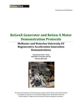
  • 1. Proprietary and Confidential ReGenX Generator and ReGen-X Motor Demonstration Protocols McMaster and Waterloo University EV Regenerative Acceleration Innovation Demonstrations Prepared by Thane C. Heins ReGenXtra Co-founder and CTO February 20th, 2017 This document outlines the demonstration protocols which will be used to demonstrate and explain the operation of the ReGenX Regenerative Acceleration Generator and the ReGen-X Regenerative Acceleration Motor prototype innovations.
  • 2. Proprietary and Confidential 2 Table of Contents 1.0 Primary Area of Research & Development.............................................................................................3 1.1 ReGenX Generator and ReGen-X Motor.............................................................................................3 2.0 ReGenX Generator Demonstration Protocol Prototype No. 1...............................................................4 2.1 Demonstration Initiation.....................................................................................................................5 3.0 ReGenX Generator Demonstration Protocol Prototype No. 2...............................................................7 3.1 Demonstration Initiation.....................................................................................................................7 3.2 Operating Prototype No. 2 Below the ReGenX Generator Coil’s Critical Minimum Frequency.........8 4.0 Factors that Dictate the ReGenX Generator Coil’s Regenerative Acceleration and Regenerative Braking Modes ..............................................................................................................................................9 4.1 Transitioning ReGenX Generator coil inductor operation to ReGenX Generator coil capacitor operation...................................................................................................................................................9 5.0 Regenerative Acceleration ReGen-X Motor Demonstration Part 3......................................................12 5.1 ReGen-X Motor Demonstration Initiation ........................................................................................13 6.0 Induction Motor Current; Torque and Power Factor Speed.................................................................14 7.0 Terms and Definitions...........................................................................................................................15
  • 3. Proprietary and Confidential 3 1.0 Primary Area of Research & Development 1.1 ReGenX Generator and ReGen-X Motor Investigating novel and innocuous methods of harvesting induced magnetic field energy in electric generators, electric motors and transformers. Lenz’s Law of Induction Governing the Operation of all Current Electric Generators (Electric Circuits and Machines 6th Edition Lister) 1. An induced EMF (voltage) will cause a current to flow in a closed circuit in such a direction that its magnetic effect will produce a Counter-Electromagnetic-Torque which will oppose the change that produces it. 2. This law follows directly from the Law of Conservation of energy; that is, to cause an induced current to flow through a load and for power to be dissipated through that load requires the expenditure of energy. 3. In the case of a generator, when current flows from the generator to the load, electric energy is expended in the load. The magnetic field produced by the load current is always in a direction that causes it to react with the generator’s main field to oppose the turning action of the prime mover driving the generator. 4. Thus the greater the current magnitude supplied to the load, the greater the induced electromagnetic reaction and in turn the greater the mechanical energy required to be supplied by the prime mover. Lenz's Law of Induction is shown by the negative sign in Faraday’s Law of Induction: ReGenX Generator Principle governing Future Electric Generators The ReGenX Generator introduces a Load Current Delay into electric generator operation such that:
  • 4. Proprietary and Confidential 4 1. In a ReGenX Generator an induced voltage will cause a delayed current to flow through a load in such a direction that its delayed net magnetic effect will produce a Complementary-Electromagnetic-Torque that will assist the change that produces it. 2. The delayed net magnetic effect produced by the ReGenX Generator’s delayed net load current is always in a direction to assist the turning action of the prime mover. 3. The ReGenX Generator’s 45-90 degree load current delay which delays, in the time domain, the net induced magnetic effect in a salient pole generator coil configuration such that the load current sine wave crest (load current & induced magnetic field peak magnitude) occurs after the rotating magnetic field pole has already passed the coil’s core at top dead centre. 4. This load current delay and the subsequent delayed induced magnetic effect accelerates the rotor pole magnet’s departure away from the coil while also simultaneously accelerating the opposite rotor magnetic pole which is approaching the coil. 5. In the case of the ReGenX Generator’s operation, an induced current is caused to flow through a load and for power to be dissipated through that load but does not require the expenditure of energy. The ReGenX Generator Principle is shown by the positive sign in Faraday’s Law of Induction: 2.0 ReGenX Generator Demonstration Protocol Prototype No. 1 The ReGenX Generator demonstration consists of two prototypes. Prototype No. 1 (as shown in schematic diagram No. 1) employs a salient pole E-core upon which is wound:  a conventional low-impedance, high-current generator coil, and  a high-impedance, high-voltage ReGenX coil Prototype No. 1 is used solely for demonstration purposes in order to illustrate each coil’s load current sine wave and their relative positions to each other in the time domain on an oscilloscope. Both coils are wound on the same physical core to ensure that the voltages induced in each coil occur in the identical time domain and are produced from identical physical rotor magnetic field poles.
  • 5. Proprietary and Confidential 5 The conventional coil and the ReGenX coil are both connected to identical purely resistive loads (PF =1) to ensure that the voltage and current in each coil are in phase. The conventional coil’s load current sine wave establishes the relative physical position of the rotor magnets as they approach and pass by the E-core. 2.1 Demonstration Initiation The demonstration starts once the prime mover has accelerated Prototype No.1’s rotor up to a no-load steady-state speed and the prime mover delivers static torque to the generator’s drive shaft at close to 100% of the prime mover’s rated speed. Once Prototype No.1’s driveshaft has reached rotational equilibrium, all angular acceleration ceases and net driveshaft torque and net drive shaft mechanical power both equal 0. According to Newton’s 1st Law, when the net torque on a rotatable object is zero, it will be in rotational equilibrium and not able to acquire angular acceleration or angular deceleration unless acted upon by an outside force. According to the Work Energy Principle, the change in kinetic energy of the system i.e. an increase or a decrease in its kinetic energy, is equal to the net work performed on the system. Once rotational equilibrium has been reached, the conventional generator coil is engaged, a closed circuit is established, load current is allowed to flow from the coil through the load and energy is dissipated in the load. The conventional generator coil is observed to operate according to Lenz’s Law whereby:  System deceleration is observed denoting that the net drive shaft torque and mechanical power have both decreased.  Work is performed by the conventional coil’s induced magnetic field energy and Counter-Electromotive-Torque that is produced which reduces the net drive shaft torque, mechanical drive-shaft power, system speed and system kinetic energy.  A prime mover input power increase is observed denoting that the prime mover is delivering increasing amounts of dynamic torque and mechanical power to the generator’s drive shaft.  Eventually the prime mover’s increased torque delivered to the drive shaft is enough to reestablish dynamic rotational equilibrium and a new steady-state speed can be observed which is reduced from the original no-load speed.  In order to reestablish the higher operating speed which was originally established at no load, additional power must be supplied to the prime mover and additional work must be performed whereby the drive shaft torque and mechanical power must be increased sufficiently enough to overcome the conventional generator’s load current induced magnetic field energy and the Counter-Electromagnetic-Torque and the work it performs changing (reducing) the kinetic energy of the system according to the Work-Energy Principle.  The load current magnitude flowing from the coil through the load can be observed.  The conventional generator coil’s load current sine wave can be observed on the oscilloscope.
  • 6. Proprietary and Confidential 6 With the conventional generator coil still engaged and while the coil’s magnetic field energy, created around the conventional generator coil’s windings, is still performing work decelerating the system via its induced Counter-Electromagnetic-Torque and while at rotational equilibrium, the ReGenX Generator coil is then placed on load and connected to its identical purely resistive load. The ReGenX Generator coil is observed to operate according to the ReGenX Generator Principle whereby:  System Regenerative Acceleration is observed denoting that the net drive shaft torque and mechanical power have both increased.  The load current magnitude and power dissipated through the load can be observed to be increased instantaneously.  A prime mover input power decrease is observed denoting that the prime mover is doing less work and is delivering decreased amounts of torque and mechanical power to the generator’s drive shaft due to the Complementary-Electromagnetic-Torque produced by the ReGenX Generator coil’s delayed load current while the generator’s output, current voltage and power dissipated in the load (work being performed) have all increased.  The instantaneous load current increase aspect of ReGenX Generator operation over the conventional coil’s load current magnitude is not due to increased rotor frequency and an increase in magnetic flux change rate in the coil, but rather is due to Flux Harvesting whereby the ReGenX Generator coil’s discharging induced magnetic field energy from the ReGenX coil performs two forms of work: 1) accelerating the generator’s rotor and increasing the kinetic energy of the system, and 2) increasing the magnitude of the changing magnetic fields in the conventional coil (rotor magnetic flux + ReGenX Generator induced flux) and subsequently the conventional coil’s induced voltage and current and the power dissipated through the load and the work performed.  Flux Harvesting occurs because the ReGenX Generator coil’s net discharging magnetic field polarity is the same direction as the rotor’s magnetic field polarity and they add together .  Eventually the ReGenX Generator’s dynamic torque delivered to the drive shaft plateaus and dynamic rotational equilibrium is reestablished. A new steady-state speed can be observed which is increased above the original no-load steady-state speed.  System on-load steady-state speed is observed to be increased over the original idle no load steady state speed.  Prime mover input power consumption with the ReGenX Generator on load is observed to be less than what was required at idle on no load.  In order to reestablish the original reduced operating speed which was originally established at no load, a further reduction in input power must be supplied to the prime mover and reduced work must be performed by the prime mover. The drive shaft torque and mechanical power must be decreased sufficiently enough to compensate adequately for the ReGenX Generator’s delayed load current, the delayed induced magnetic field energy, the Complementary-Electromagnetic- Torque, and the work it performs changing (increasing) the kinetic energy of the system according to the Work- Energy Principle.
  • 7. Proprietary and Confidential 7  The conventional generator coil’s and ReGenX Generator coil’s load current sine waves can both be observed on the oscilloscope where the ReGenX Generator’s load current sine wave can be observed to be delayed by about 50 degrees. 3.0 ReGenX Generator Demonstration Protocol Prototype No. 2 Prototype No. 2 (as shown in schematic diagram No 2) employees salient pole C cores upon which are wound:  two individual low-impedance, high-current ReGenX Generator coils. Prototype No. 2 represents the ReGenX Generator’s mature IP in commercialization- readiness mode. Prototype No. 2 is designed to demonstration the ReGenX Generator operating in Regenerative Acceleration Mode above the coil’s Critical Minimum Frequency and in regenerative braking mode below it. Both ReGenX coils charge lead acid batteries when placed on load. 3.1 Demonstration Initiation The demonstration starts once the prime mover has accelerated Prototype No.2’s rotor up to a no-load steady-state speed and the prime mover delivers static torque to the generator’s drive shaft at close to 100% of the prime mover’s rated speed. Once Prototype No.2’s driveshaft has reached rotational equilibrium and all angular acceleration has ceased, the net driveshaft torque and net mechanical power both equal zero. As with Prototype No. 1 and also according to Newton’s 1st Law; when the net torque on a rotatable object is zero, it will be in rotational equilibrium and not able to acquire angular acceleration or angular deceleration unless acted upon by an outside force. According to the Work-Energy Principle, the change in kinetic energy of the system i.e. an increase or a decrease in its kinetic energy, is equal to the net work performed on the system. Once rotational equilibrium has been reached, the ReGenX Generator coils are placed on load, a closed circuit is established and load current is allowed to flow from the ReGenX coils through the loads and energy is stored in the loads. The ReGenX Generator coils are observed to operate according to the ReGenX Generator Principle whereby:  System Regenerative Acceleration is observed denoting that the net drive shaft torque and net mechanical power have both increased.  A prime mover input power decrease is observed denoting that the prime mover is doing less work and is delivering decreased amounts of torque and mechanical power to the generator’s drive shaft due to the Complementary-Electromagnetic-Torque
  • 8. Proprietary and Confidential 8 produced by the ReGenX Generator coil’s delayed load current while the generator’s output is doing work charging the batteries.  The greater the magnitude of work performed by the ReGenX Generator coils (i.e. the greater the generator’s load current magnitude and the faster the rate of battery recharge), the greater the reduction in prime mover energy and supplied work and drive shaft torque.  The instantaneous load current increase aspect of ReGenX Generator’s Flux Harvesting can also be observed between the two ReGenX Generator coils whereby ReGenX Generator coil No. 1’s discharging induced electromagnetic field energy is collected in ReGenX Generator coil No. 2’s core, increasing the net flux magnitude in the coil’s core and vice versa such that the rotor supplied magnetic flux and each ReGenX coil’s induced electromagnetic fluxes add together.  It is observed that the magnetic field energy delivered by the ReGenX coil performs two forms of work: 1) accelerating the generator’s rotor and increasing the kinetic energy of the system, and 2) charging and storing energy in the batteries.  Eventually the ReGenX Generator’s dynamic torque delivered to the drive shaft plateaus and transitions to delivering static torque. Rotational equilibrium is reestablished and a new steady state speed can be observed.  New system on load steady state speed is observed to be increased over idle no load steady state speed.  Prime mover input power consumption is observed to be less than what was required at idle on no load.  In order to reestablish the original reduced no load operating speed, a further reduction in input power must be supplied to the prime mover. Reduced work must be performed by the prime mover whereby the drive shaft torque and mechanical power must be decreased sufficiently enough to compensate adequately for the ReGenX Generator’s delayed load current and the delayed induced magnetic field energy that produced the Complementary-Electromagnetic-Torque and the work it performs changing (increasing) the kinetic energy of the system according to the Work-Energy Principle. 3.2 Operating Prototype No. 2 Below the ReGenX Generator Coil’s Critical Minimum Frequency The ReGenX Generator coils in Prototype No. 2 may also be operated as conventional generator coils in regenerative braking mode which is accomplished by operating the coils below their Critical Minimum Frequency. The demonstration starts once the prime mover has accelerated Prototype No.2’s rotor up to a no load steady state speed and the prime mover delivers static torque to the generator’s drive shaft at close to 75% of the prime mover’s rated speed. Once rotational equilibrium has been reached, the ReGenX Generator coils are placed on load, a closed circuit is established and load current is allowed to flow from the ReGenX coils through the loads, and energy is stored in the loads. The ReGenX Generator coils when operated below the Critical Minimum Frequency are observed to operate as conventional, regenerative braking generator coils and according to Lenz’s Law of Induction whereby:
  • 9. Proprietary and Confidential 9  System deceleration is observed denoting that the net drive shaft torque and mechanical power have both decreased.  Work is performed by the ReGenX coils in conventional mode and an induced magnetic field energy and a Counter-Electromagnetic-Torque is produced which reduces the net drive shaft torque, mechanical drive shaft power, system speed and system kinetic energy while the battery is being charged.  A prime mover input power increase is observed denoting that the prime mover is delivering increasing amounts of dynamic torque and mechanical power to the generator’s drive shaft. 4.0 Factors that Dictate the ReGenX Generator Coil’s Regenerative Acceleration and Regenerative Braking Modes 4.1 Transitioning ReGenX Generator coil inductor operation to ReGenX Generator coil capacitor operation Inductors (generator coils) store energy in the Electromagnetic Field around the coil when a closed circuit is created and when current flows in the coil and to the load. It is this magnetic field energy that is responsible for the Counter-Electromotive-Torque produced and the work performed when an electric generator reduces the kinetic energy of a prime mover/electric generator system which is colloquially referred to as regenerative braking in electric vehicles. Normally the self-induced parasitic capacitance of an inductor or conventional generator coil can be negated at low frequencies, but as frequency increases the parasitic capacitance increases. However an ideal inductor would not behave like a capacitor, but in the real world there is no such thing as ideal components. Basically, any real inductor can be thought of an ideal inductor that has a resistor in series with it (wire resistance) and a capacitor in parallel with it (parasitic capacitance). Now, where does the parasitic capacitance come from? An inductor is made out of a coil of insulated wire, so there are tiny capacitors between the windings (since there are two sections of wire separated by an insulator). Equivalent circuit of an inductor
  • 10. Proprietary and Confidential 10 Each section of windings is at a slightly different potential (due to wire inductance and resistance). As the frequency of operation increases, the impedance of the inductor increases while the impedance of the parasitic capacitor decreases, so at a high enough frequency the impedance of the parasitic capacitance is much lower than the impedance of the inductor, which means that the inductor transitions from inductor operation and begins to operate as a capacitor. The inductor transitions from storing energy externally in the Electromagnetic Field and begins to store energy internally in the Electrostatic Field between the windings. Inductor impedance (Zt) increase with frequency (F): Zt = Xl + Rdc = 2∏FL + Rdc Where: Zt is total inductor impedance, Xl is inductor reactance, F is operating frequency, L is coil inductance, and Rdc is inductor DC wire resistance Capacitors store energy in the Electrostatic Field between the plates of the capacitor. In the case of the ReGenX coil/inductor, energy is stored between the windings in the electrostatic field where the windings act as the plates of the capacitor and the air between them is the dielectric. Essentially for all intents and purposes, a ReGenX Generator coil when operating above its Critical Minimum Frequency can be viewed as operating as a multi-plate parallel capacitor storing energy internally and then releasing energy externally.
  • 11. Proprietary and Confidential 11 Inductors resist and delay the buildup and flow of current and capacitors resist and delay the buildup of voltage. Eventually however the voltage induced in the ReGenX coil exceeds the (air) dielectric’s ability to contain and delay it, the dielectric breaks down and current begins to flow in the coil to the load. The induced AC voltage stored capacitively in between the ReGenX coils’ windings is then released but is further delayed by the ReGenX coil’s 5-Time Constant Rise time and the coil’s core hysteresis time delay. Together when these three individual time delays are each added together, they are enough to produce the ReGenX Generator coil’s 50 degree load current delay which was observed on the oscilloscope in ReGenX Prototype No. 1. All inductors also have their own resonance frequency. This is why some high frequency inductors have their windings far apart - to reduce the buildup of parasitic capacitance. The ReGenX Generator coil on the other hand has its windings wound tightly together and uniformly and precisely spaced with each layer placed directly on top of each other such that each layer is placed directly on top of the preceding layer. This encourages the buildup of mutual capacitance between the layers and also between each individual winding.
  • 12. Proprietary and Confidential 12 5.0 Regenerative Acceleration ReGen-X Motor Demonstration Part 3 Prototype No. 3 (as shown in schematic diagram No 3) is a pulsed DC motorized version on the ReGenX Generator Prototype No. 2. In conventional electric motor design, electric current is caused to flow in the windings that make up the motor coils; the result is electromagnetic fields are produced around the coils which accelerate the motor’s rotor and the motor’s drive shaft. The direction of current in the motor coils is alternated rapidly in order to adequately affect the rotors alternating magnetic pole polarities. The magnetic field energy pulse once used to initiate rotation is allowed to dissipate into free space. The ReGen-X Motor employs a pulsed DC motor circuit which employs DC current to produce electromagnetic fields around the motor coils as per any conventional motor but it does not allow the magnetic field energy to be wasted and dissipated into free space. Instead, once the motor’s DC current pulse has ceased, a switch in the motor circuit is activated which allows the collapsing magnetic field energy to be directed back into a battery in Flyback Magnetic Field Collection Mode. The magnitude of return current returning to and charging the batteries in Flyback Magnetic Field Collection Mode is determined by the DC resistance losses in the motor coil’s windings and the motor coil’s core losses. Once the motor pulse has ceased and the motor circuit initiates Flyback Magnetic Field Collection Mode, the motor circuit and motor coil also simultaneously enter Motor Regenerative Acceleration Generator Mode, the duration of which continues through the duration of the following rotor magnetic field pole’s trajectory past the coil’s core. The result is collapsing magnetic field energy being converted back into electrical energy that charges the battery in concert with rotor magnetic field flux that simultaneously charges the battery in tandem. The ReGen-X Motor does not alternate current and electromagnetic field pulse direction with each alternating rotor magnetic field pole, but rather only pulses on identical rotor poles. Alternating rotor magnetic field poles provide the Regenerative Acceleration generator action in concert with Flyback Magnetic Field Collection.
  • 13. Proprietary and Confidential 13 The advantages are: 1. Decreased amounts of electromagnetic pollution produced by the motor emanating into free space. 2. Reduced core losses due to hysteresis since the cores magnetic field domains do not have to be forcefully reversed by the motor current. 3. Recycling and recollection of a portion of the original input current. 4. Natural generator action in the motor. 5.1 ReGen-X Motor Demonstration Initiation The ReGen-X Motor demonstration begins with a motor drive shaft that is at equilibrium. Electric current is initially sent to the motor circuit.  The ReGen-X Motor drive shaft begins to provide dynamic torque and angular acceleration.  The input current to the ReGen-X Motor coil can be observed.  The output current from the motor circuit charging the battery and the battery charge voltage can be observed.  Variations in motor speed and corresponding variations in battery charging current magnitudes and rate of battery charging can also be observed.
  • 14. Proprietary and Confidential 14 6.0 Induction Motor Current; Torque and Power Factor Speed
  • 15. Proprietary and Confidential 15 7.0 Terms and Definitions Page 4 ReGenX Generator Load Current Time Delay:  The ReGenX Generator Load Current Time Delay is a culmination of capacitor energy storage and release + inductor 5 time constant rise time + core hysteresis. ReGenX Generator Principle:  An induced EMF (voltage) will cause a current to flow in a closed circuit in such a direction that its magnetic effect will produce a Complementary-Electromagnetic- Torque which will assist the change that produces it.  ReGenX Law of Induction is shown by the positive sign in Faraday’s Law of Induction Sine Wave Crest:  Denotes the peak sine wave amplitude. Top Dead Centre (TDC): As the rotor magnetic field pole approaches the coils core the amplitude of the current sine wave increases until it reaches maximum at TDC. At TDC the rotor magnetic field pole is neither approaching nor receding from the coil’s core. Prior to TDC the current magnitude is increasing and post TDC the current has changed direction and begins decreasing towards the opposite rotor pole’s TDC point at the Trough. ReGenX Generator Salient Pole E Coil:  The salient pole E coil is an E shaped core with a ReGenX Generator coil wound on the middle finger with a conventional winding circling the outside perimeter of the core.
  • 16. Proprietary and Confidential 16  The conventional coil provides conventional generator action or electric vehicle regenerative braking while the ReGenX coil provides Regenerative Acceleration. Page 5 Static Torque:  Torque can be either static or dynamic.  A static torque is one which does not produce an angular acceleration.  A dynamic torque produces an angular acceleration. Rotational Equilibrium:  The concept of rotational equilibrium is an equivalent to Newton’s 1ˢᵗ law for a rotational system. An object which is not rotating remains not rotating unless acted on by an external torque. Similarly, an object rotating at constant angular velocity remains rotating unless acted on by an external torque.  The concept of rotational equilibrium is particularly useful in problems involving multiple torques acting on a rotatable object. In this case it is the net torque which is important. If the net torque on a rotatable object is zero then it will be in rotational equilibrium and not able to acquire angular acceleration. Drive Shaft Mechanical Power:  In rotational systems, power is the product of the torque τ and angular velocity ω, Work-Energy Principle:  The work-energy principle states that an increase in the kinetic energy of a rigid body is caused by an equal amount of positive work done on the body by the resultant force acting on that body. Conversely, a decrease in kinetic energy is caused by an equal amount of negative work done by the resultant force. 100% of the Prime Mover’s Rated Speed:  Approximately 3450 R PM.
  • 17. Proprietary and Confidential 17 Page 7 Critical Minimum Frequency:  Is the minimum operating frequency required for the ReGenX Generator to provide Regenerative Acceleration. i.e. load power delivery and system acceleration / Complementary Electromagnetic Torque.  It is the transition point where the ReGenX Generator coil ceases to store energy in the electromagnetic field as an inductor and begins to store energy internally in the electrostatic field as a capacitor.  Below the Critical Minimum Frequency the ReGenX Generator operates as a conventional generator and provides regenerative braking effects / Counter Electromagnetic Torque.  The Critical Minimum Frequency for an individual coil can be raised or lowered as required. Page 8 Flux Harvesting:  Flux Harvesting occurs when the discharging induced electromagnetic fields from a ReGenX Generator coil enter a conventional coil in the same direction and the two flux magnitudes are cumulative.  Flux Harvesting also occurs between ReGenX Generator coils.  Flux Harvesting occurs in the ReGen-X Motor when the motor’s pulsed magnetic field is allowed to collapse back into a battery. 75% of the Prime Mover’s Rated Speed:  Approximately 2000 RPM Page 11 Inductor 5 Time Constant Rise Time:  When a current is applied to an inductor it takes some time for the current to reach its maximum value, after which it will remain in a "steady state" until some other event causes the input to change. The time taken for the current to rise to its steady state value in an LR circuit depends on: •The resistance (R) This is the total circuit resistance, which includes the DC resistance of the inductor (RL) itself, plus any external circuit resistance. • The inductance of L Which is proportional to the square of the number of turns, the cross sectional area of coil and the permeability of the core.
  • 18. Proprietary and Confidential 18 Page 12 Flyback Magnetic Field Collection Mode:  Collapsing ReGen-X Motor coil magnetic field harvesting. Hysteresis  The time lag or delay of a magnetic material known commonly as Magnetic Hysteresis, relates to the magnetization properties of a material by which it firstly becomes magnetised and then de-magnetised and the energy and time required to change it.