SlideShare uma empresa Scribd logo
1 de 26
Baixar para ler offline
5/1
5
Lightning and Overvoltage
Protection Devices
General Data 5/2 Product overview
5/3 Introduction
Lightning Arresters 5/7 Requirement category B,
type 1, class I
Arrester Combinations 5/10 Requirement category B and C,
type 1 and 2, class I and II
Surge Arresters 5/13 Narrow version, requirement
category C, type 2, class II
5/16 Wide version, requirement
category C, type 2, class II
5/20 Multipole, requirement category D,
type 3, class III
Surge Protection
Adapters
5/22 Requirement category D,
type 3, class III
Accessories 5/25 For lightning and overvoltage
protection devices
Lightning and Overvoltage Protection Devices
General Data
Product overview
5/2 Siemens ET B1 T · 2007
■Overview
1 MWmodular width 18 mm
Lightning arresters – requirement category B, type 1, class I
• Plug-in protective blocks
• TN-C, TN-S and TT systems
• Rated arrester voltage Uc 350 V AC
• Lightning current 50 ... 100 kA
• All versions with remote indication contact
• Installation location: Main distribution board, upstream or
downstream from the counter
Arrester combinations– requirement category B and C, type 1 and 2, class I and II
• Plug-in protective blocks
• TN-C, TN-S and TT systems
• Rated arrester voltage Uc 350 V AC
• Lightning current 50 ... 100 kA
• All versions with remote indication contact
• Installation location: Main distribution board
Surge arresters, narrow version – requirement category C, type 2, class II
• Plug-in protective blocks
• 2, 3 and 4-pole (TN-C, TN-S and TT systems)
• Rated arrester voltage Uc 350 V AC
• Rated discharge current 20 kA
• Discharge surge current 40 kA
• Version without or with remote indication contact
• Installation location: Sub-distribution board
• Mounting width 12 mm/pole
Surge arresters, wide version – requirement category C, type 2, class II
• Plug-in protective blocks or compact version
• 1, 2, 3 and 4-pole (TN-C, TN-S and TT systems)
• Rated arrester voltage Uc 350 V AC
• Rated discharge current 20 kA
• Discharge surge current 40 kA
• Version without or with remote indication contact
• Installation location: Sub-distribution board
• Mounting width 18 mm/pole (1 MW/pole)
Surge arresters – requirement category D, type 3, class III
• Plug-in protective blocks
• For 1-phase and 3-phase systems
• Rated voltage
- 1-phase AC/DC 24 V, 60 V, 120 V, 230 V
- 3-phase system AC 230/400 V
• Monitoring device
• Installation location: As close as possible upstream from
the terminal equipment
Surge protection adapters – socket outlets, socket outlet adapters and combination protective devices
• Can be plugged into 5 socket outlets
• Status display
• Permanent thermal monitoring of the protection circuit
Accessories
• Male connectors for lightning and surge arresters
• Through-type terminals
• Busbars
Lightning and Overvoltage Protection Devices
General Data
Introduction
5/3Siemens ET B1 T · 2007
1
2
3
4
5
6
7
8
9
10
11
12
13
14
15
16
17
■Overview
Introduction to lightning and overvoltage protection
Overvoltage destroys a considerable number of electrical and
electronic devices and units. And the damage is not limited to
just industrial and commercial facilities. Building management
systems as well as household appliances for daily use are also
affected.
Without effective protection against overvoltage there is a real
risk of costly repairs or replacement purchases due to the dam-
age done to equipment.
Listed below are units from various sectors which have sensitive
electronic circuitry and are frequently destroyed by overvoltage.
Clearly, protective measures for preventing overvoltage-related
damage are just as important to private households as for the
commercial and industrial sectors. An effective overvoltage pro-
tection concept for building management systems covers power
supply, telephone, aerial/reception, data processing and control
systems. What is important is that all the cables connected to a
device are linked to a suitable surge arrester. Nearly all devices
have a power supply. A television set, for example, also needs a
reception signal which is supplied over an aerial cable. And re-
gardless of whether the signal comes from an aerial or a wide
band cable, both the aerial input and power supply to the televi-
sion set should be protected. The need for such consistent all-
round protection applies equally to all other devices and units.
Building management systems and industry
• Heating controls
• Outdoor lighting
• Shutter controls
• Garage door actuators
• Central I&C
• Air conditioning
• Alarm systems
• Fire alarms
• Video surveillance
• Process computers
Office equipment
• Computers
• Printers
• Telecommunication systems
• Fax machines
• Copying machines
Private households
• Dishwashers
• Automatic washing machines
• Clothes dryers
• Coffee-makers
• Radio alarm clocks
• Refrigerators
• Deep-freezers
• Microwave ovens
• Electric cookers
• Telephone systems
Hobbies and leisure
• Television sets
• Aerial amplifiers
• Video recorders
• DVD players
• Hifi systems
• Computers
• Electrical musical instruments
• CB radio systems
In relation to the total value of the equipment concerned, the cost
of installing suitable protective devices usually pays for itself
when just a single unit of electrical equipment is saved just once
from destruction . Provided the performance parameters are not
exceeded, surge suppressors work many times, thus increasing
the benefits for the user several-fold.
The comprehensive surge protection concept
Fundamentals
Transient overvoltage results from lightning discharges, switch-
ing operations in electrical circuits and electrostatic discharges.
Without the protection provided by lightning arresters and over-
voltage protection equipment, even the robustly constructed
low-voltage supply systems of buildings or industrial plants are
unable to cope with a lightning discharge. The overvoltage
occurs only very briefly for millionths of a second. Nevertheless,
the mostly very high voltages involved are capable of destroying
electronic circuitry or the insulation between the conductors on
printed circuit-boards. And even if an electrical or electronic
device has passed the voltage withstand test according to
IEC 100045, as required for being awarded the CE symbol, it is
still not in a position to withstand unscathed all environmental
influences with regard to electromagnetic compatibility (EMC).
To prevent the destruction of electrical equipment by overvolt-
age, all endangered interfaces such as signal inputs and power
supplies must be connected to overvoltage protection equip-
ment. What is needed, depending on the case of application,
are components such as spark gaps, gas-filled surge arresters,
varistors and suppressor diodes, which because of the differ-
ences in their arresting and limiting specifications are arranged
singly or as combinations in a protection circuit.
The following damage can be caused by overvoltage
Overvoltage endangers and destroys a considerable number of
electrical and electronic installations. In the last few years there
has been a sharp increase in the frequency of incidents and the
total costs of the damage incurred. The statistics published by
property insurance companies have a clear tale to tell. Damage
to devices and their destruction occur all the more often when
devices need to be in permanent standby.
Repairs and replacement purchases are not the only expense
factor, however. Costs also arise through not being able to use
the affected system components and possibly even through loss
of software and data. The damage profiles generally cover
everything from destroyed cables, printed circuit-boards and
switching devices to substantial mechanical destruction of the
building installations. This damage can be reliably prevented by
lightning arresters, surge suppressors and arrester combina-
tions.
Lightning and Overvoltage Protection Devices
General Data
Introduction
5/4 Siemens ET B1 T · 2007
Lightning and overvoltage protection – WHY?
Powerful information systems form the backbone of our modern
industrial society. A fault or the failure of these types of systems
can have far-reaching consequences. These can even cause
service and industry companies to go bankrupt.
The cause of faults are many and electromagnetic influences
play a major role. In a highly technical, electromagnetic environ-
ment, it is not advisable to simply wait for the mutual influencing
of electrical and electronic devices and systems and then pay
good money to eliminate the resulting problems. Rather it is es-
sential to plan and take preventative measures that reduce the
risk of influences, faults and destruction.
In spite of all this, the damage and loss statistics of electronic in-
surance companies are extremely worrying: More than a quarter
of all claims are as a result of overvoltages due to electromag-
netic influences.
Source: The causes of damage to electronics in 2001, analysis of 7370
claims Württembergische Versicherungs AG.
Causes of overvoltage
Depending on their cause, overvoltages are divided into two cat-
egories:
• LEMP (Lightning ElectroMagnetic Pulse) – overvoltages,
caused by atmospheric influences (e.g. direct lightning
strikes, electromagnetic lightning fields).
• SEMP (Switching ElectroMagnetic Pulse) – overvoltages
caused by switching operations (e.g. disconnection of short-
circuits, normal switching of loads).
Overvoltages that are the result of thunderstorms are caused by
direct/close-up or remote strikes (see diagram on page 5/5).
Direct or close-up strikes are lightning strikes to the lightning
protection system of a building, its immediate proximity or to the
electrical conductive systems of a building (e.g. l.v. power sup-
ply, TC and control lines). The resulting surge currents and volt-
ages are a particular threat to the system to be protected due to
their amplitude and power.
In the case of direct or close-up lightning strikes, the overvoltag-
es (see diagram on page 5/5) are caused by the voltage drop at
the surge grounding resistance and the resulting increase in
potential of the building, compared to the distant environment.
This represents the greatest possible loading of an electrical
plant in buildings.
The characteristic parameters of the surge current (peak value,
rate of current rise, charge content, specific energy) can be de-
scribed using the surge current waveform 10/350 µs (see dia-
gram: examples of impulse test currents). These are defined in
the international, European and national standards as test cur-
rent for components and devices for protection in the event of
direct strikes.
In addition to the voltage drop at the surge grounding resis-
tance, overvoltages also occur in electrical building installations
and the connected systems and devices, due to the induction
effect of the electromagnetic lightning field (see diagram on
page 5/5: Example 1b).
The energy of these induced overvoltages and the resulting
pulse currents is considerably less than that of a direct lightning
impulse current and is therefore only described with surge cur-
rent wave 8/20 µs (see diagram: Examples of impulse test
currents). Components and devices that do not carry currents
from direct lightning strikes are therefore checked using surge
currents 8/20 µs.
Examples of impulse test currents
The protection concept
Remote strikes are lightning strikes at a greater distance from
the objects to be protected, lightning strikes in the medium-
voltage overhead system or the immediate proximity thereof,
or lightning discharges from cloud to cloud (see diagram on
page 5/5: Cases 2a, 2b and 2c). At the same time as these in-
duced overvoltages, the effects of remote strikes on the electri-
cal system of a building are controlled through devices and
components, the dimensions of which correspond to surge cur-
rent wave 8/20 µs.
The causes of overvoltages due to switching operations in-
clude the following:
• Switching off of inductive loads
(e.g. transformers, reactors, motors),
• Ignition and interruption of electric arcs
(e.g. arc-welding device),
• Tripping of fuses.
The effects of switching operations in the electrical installation of
a building are simulated for testing purposes with surge currents
of waveform 8/20 µs.
To ensure the continuous availability of complex power and in-
formation systems, even in the event of direct lightning strikes,
further measures for overvoltage protection of electrical and
electronic systems are required as well as a building lightning
protection system. It is important to take all the causes of over-
voltages into account. For this purpose, the lightning protection
zone concept is used as described in IEC 62305-4
(DIN V VDE V 0185-4) (see diagram on page 5/6). The building
is divided into zones of different danger levels. Using these
zones, it is possible to determine the devices and components
required for the lightning and overvoltage protection.
23,7 %
15,4 %
22,9 %
5,6 %0,8 %
I2_11531a
27,1 %
4,6 %
Fire
Elementary
Overvoltages
(Lightning discharges and
Switching operations)
Other
Negligence
Water
Theft
Vandalism
s
[kA]
0
0 20 200 350400 600 800 1000
[ ]
I2_11532a
25
50
75
100
8
1
2
4
1
2
s[ ] Q [As] W/R [J/ ]
100 10/350 50 2,5 × 10⁶
8 8/20 0,1 0,4 × 10³
max [kA] Waveform
Impulse test current for
lightning arresters
Impulse test current for
surge arresters
Lightning and Overvoltage Protection Devices
General Data
Introduction
5/5Siemens ET B1 T · 2007
1
2
3
4
5
6
7
8
9
10
11
12
13
14
15
16
17
An EMC-oriented lightning protection zone concept should also
include external lightning protection (with air terminals, arrest-
ers, grounding), equipotential bonding, room insulation and
overvoltage protection for power and information systems.
For the definition of lightning protection zones (LPZ), please use
the specifications made in the table "Definition of lightning
protection zones".
Definition of lightning protection zones
According to the demands and loads made on overvoltage pro-
tection devices with regard to their installation site, these are di-
vided into lightning arresters, surge arresters and arrester com-
binations.
The highest demands with regard to discharge capacity are
made on lightning current and arrester combinations, which im-
plement the transition from lightning protection zone LPZ 0A to
LPZ 1 or LPZ 0A to LPZ 2. These surge arresters must be able to
carry lightning partial currents of waveform 10/350 µs several
times and thus prevent these destructive currents from penetrat-
ing the electrical installation of a building. At the transition of
lightning protection zone LPZ 0B to LPZ 1 the downstream light-
ning arrester at the transition area of lightning protection zones
LPZ 1 auf LPZ 2 and higher, surge arresters are installed to pro-
tect against overvoltages. It is their task to further attenuate the
remaining extent of the upstream protection level and restrict the
overvoltages in the system, whether they are induced or self-
generated.
The lightning and overvoltage protective measures at the bor-
ders of the lightning protection zones apply in equal measure to
the energy and information system. The holistic approach of the
measures described in the EMC-oriented lightning protection
zone concept means it is possible to achieve permanent plant
availability of a modern infrastructure.
Causes for overvoltages during lightning discharges
Lightning
protection
zones
Description
LPZ 0A Zone where objects are exposed to direct lightning strikes
and must therefore carry the whole lightning current. The
undamped electromagnetic field occurs in this case.
LPZ 0B Zone where objects are not exposed to direct lightning
strikes but where the undamped electromagnetic field still
occurs.
LPZ 1 Zone where objects are not exposed to direct lightning
strikes and in which the currents are reduced compared
to Zone 0A. In this zone, the electromagnetic field may be
damped, depending on the insulation measures imple-
mented.
LPZ 2,
LPZ 3
If a significant reduction in the conducted currents and/ or
the electromagnetic field is required, subsequent zones
must be set up. The demand on these zones must be
geared towards the required environment zones of the
system to be protected.
I 2 _ 1 0 7 8 3
R s t
2 b
1
2 a
2 c
2 0 k V
L 1
L 2
L 3
P E N
1
1 a
1 b
2 a
2 b
2 c
1 b
1 a
D i r e c t / c l o s e - u p s t r i k e
Strike in outer lightning protection,
Process framework (in industrial plants),
Cables, etc.
Voltage drop at
surge grounding resistance R
Induced voltage in loops
I T s y s t e m
P o w e r
s y s t e m
st
R e m o t e s t r i k e :
Strike in medium-
voltage overhead lines
Overvoltage transformer
waves on overhead lines,
as a result of
cloud-cloud lightning strikes
Fields of lightning channel
Lightning and Overvoltage Protection Devices
General Data
Introduction
5/6 Siemens ET B1 T · 2007
EMC-oriented lightning protection zone concept
M
A
B B
L E M P
L E M P
L E M P
B
S E M P
I2_11533
R o o m i n s u l a t i o n
V e n t i l a t i o n
T e r m i n a l
P o w e r -
e n g i n e e r i n g
s y s t e m
I T s y s t e m
L i g h t n i n g p r o t e c t i o n
e q u i p o t e n t i a l b o n d i n g
L i g h t n i n g c o n d u c t o r
L o c a l e q u i p o t e n t i a l b o n d i n g
S u r g e a r r e s t e r
L P Z 0
L P Z 1
L P Z 2
L P Z 1
L P Z 0 L P Z 0
L P Z 3
L P Z 2
L P Z 0
Lightning and Overvoltage Protection Devices
Lightning Arresters
Requirement category B, type 1, class I
5/7Siemens ET B1 T · 2007
1
2
3
4
5
6
7
8
9
10
11
12
13
14
15
16
17
■Benefits
• Type 1 lightning arresters do not require decoupling reactors
to be fitted in the plant. This simplifies plant configuration and
reduces space requirements. No time is wasted on planning
the installation of decoupling reactors. This also considerably
cuts costs.
• The rated arrester voltage is a uniform 350 V AC. This in-
creases safety in systems with extended voltage overshoots.
• All lightning arresters are fitted with a mechanical fault indica-
tion, which does not require an extra power supply. This
means they can be installed in the precounter area, where
electrical plants can be protected particularly effectively.
• The protective modules are plug-in versions. No mounting
work required when replacing the protective modules. When
taking insulation measurements, the protective modules are
simply removed, no need to disconnect the power supply.
• All type 1 lightning arresters are fitted with a remote indication
contact, which is inserted in the device and does not require
any further space. A remote signaling is always possible, even
in the event of a power failure.
■Application
• Type 1 lightning arresters include the system cables in the
equipotential bonding, which protects the low-voltage
systems against the overvoltages and high surge currents that
can be triggered by direct or indirect lightning strikes.
• The protection level is lowered to 1.5 kV by the lightning ar-
rester, which reduces the load on the plant if a lightning strike
is discharged.
• The lightning arresters are enclosed and are suitable for
installation in the precounter area.
• Tested by wave-shaped lightning impulse, 25/100 kA with
waveform 10/350 µs.
■Technical specifications
Design Lightning arresters
Order No. 5SD7 412-1 5SD7 413-1 5SD7 414-1
Approvals KEMA (available soon)
Requirement category B to E DIN VDE 06754-6;
SPD class I according to IEC 61643-11;
SPD type 1 according to EN 61643-1
Rated voltage UN V AC 230/400 230/400 230/400
Rated arrester voltage Uc
• L/N, N/PE, L/PEN V AC 350 350 350
Lightning impulse current Iimp (10/350 µs)
• L/N or L/PEN, 1-pole/3-pole kA 25/100 25/75 25/100
• N/PE kA 100 -- 100
Rated discharge surge current In (8/20 µs)
• L/N or L/PEN, 1-pole/3-pole kA 25/100 25/75 25/100
• N/PE kA 100 -- 100
Protection level Up
• L/N, N/PE, L/PEN kV ≤1.5 ≤1.5 ≤1.5
Follow current discharge capacity Ifi (AC)
• L/N or L/PEN kA 50 50 50
• N/PE A 100 -- 100
Response time tA
• L/N or L/PEN ns ≤100 ≤100 ≤100
• L-(N)-PE ns ≤100 -- ≤100
Max. required back-up protection A 315 gL/gG 315 gL/gG 315 gL/gG
Short-circuit strength at max. back-up
protection
kArms 50 50 50
TOV voltage UT
• L/N V/s 415/5 415/5 415/5
• N/PE V/ms 1200/200 -- 1200/200
Temperature range °C -40 ... +80
Degree of protection IP20
Conductor cross-section
• Finely stranded mm2
0.5 ... 25
• Solid mm2
0.5 ... 35
Mounting width according to DIN 43880 MW 4 6 8
Remote signaling yes
Contact type Floating CO contact (plug-in)
Operational voltage, max. V AC 250
V DC 125
Operational current, max.
• Resistive/inductive load AC 1 A/1 A
• Resistive/inductive load DC 0.2 A/30 mA
Conductor cross-section
• Finely stranded/solid mm2
1.5/1.5
Lightning and Overvoltage Protection Devices
Lightning Arresters
Requirement category B, type 1, class I
5/8 Siemens ET B1 T · 2007
■Selection and ordering data
■Dimensional drawings
2-pole
5SD7 412-1
3-pole
5SD7 413-1
Dis-
charge
capacity
MW Order No. Weight
1 unit
approx.
PS*/
P. unit
kA kg Unit(s)
Lightning arresters
2-pole
for TT and TN-S systems 100 4 5SD7 412-1 0.732 1
3-pole
for TN-C systems 75 6 5SD7 413-1 0.909 1
4-pole
for TT and TN-S systems 100 8 5SD7 414-1 1.310 1
I2_12719
45
90
99
43,56,772
64
RS
I2_12720
45
90
99
43,56,7108
64
RS
* You can order this quantity or a multiple thereof.
Lightning and Overvoltage Protection Devices
Lightning Arresters
Requirement category B, type 1, class I
5/9Siemens ET B1 T · 2007
1
2
3
4
5
6
7
8
9
10
11
12
13
14
15
16
17
4-pole
5SD7 414-1
■Schematics
2-pole
5SD7 412-1
3-pole
5SD7 413-1
4-pole
5SD7 414-1
I2_12721
45
90
99
43,56,7144
64
RS
PE L1
N
I2_12565
12 14
11
RS
L1 L2 L3
PEN
I2_12566
12 14
11
RS
PE L1 L2 L3
N
I2_12567
12 14
11
RS
Lightning and Overvoltage Protection Devices
Arrester Combinations
Requirement category B and C,
type 1 and 2, class I and II
5/10 Siemens ET B1 T · 2007
■Benefits
• Type 1 and 2 arrester combinations do not require decoupling
reactors to be fitted in the plant. This simplifies plant configu-
ration and reduces space requirements. No time is wasted on
planning the installation of decoupling reactors. This also con-
siderably cuts costs.
• The rated arrester voltage is a uniform 350 V AC. This
increases safety in systems with longer voltage overshoots.
• All arrester combinations are fitted with a mechanical fault in-
dication, which does not require an extra power supply.
• The protective modules are plug-in versions. No mounting
work required when replacing the protective modules. When
taking insulation measurements, the protective modules are
simply removed, no need to disconnect the combination
arrester from the power supply.
• The same type 2, class II overvoltage protective modules are
used as for the slim version of the surge arresters (5SD7 42.).
This simplifies stock-keeping.
• All arrester combinations are fitted with a remote indication
contact, which is inserted in the device and does not require
any further space. A remote signaling is always possible, even
in the event of a power failure.
■Application
• Type 1 and 2 arrester combinations include the system cables
in the equipotential bonding, which protects the low-voltage
systems against the overvoltages and high currents that can
be triggered by direct lightning strikes.
• The protection level is lowered to 1.5 kV by the arrester com-
binations, which reduces the load on the plant if a lightning
strike is discharged.
• Tested by wave-shaped lightning impulse, 25/100 kA with
waveform 10/350 µs.
• A thermal isolating arrester disconnector offers a high degree
of protection against overload during runtime.
■Technical specifications
Design Arrester combinations
Order No. 5SD7 442-1 5SD7 443-1 5SD7 444-1
Approvals KEMA (available soon)
Requirement category B to E DIN VDE 06754-6;
SPD class I according to IEC 61643-11;
SPD type 1 according to EN 61643-1
Rated voltage UN V AC 230/400 230/400 230/400
Rated arrester voltage Uc
• L/N, N/PE, L/PEN V AC 350 350 350
Lightning impulse current Iimp (10/350 µs)
• L/N or L/PEN, 1-pole/3-pole kA 25/100 25/75 25/100
• N/PE kA 100 -- 100
Rated discharge surge current In (8/20 µs)
• L/N or L/PEN, 1-pole/3-pole kA 25/100 25/75 25/100
• N/PE kA 100 -- 100
Protection level Up
• L/N, N/PE, L/PEN kV ≤1.5 ≤1.5 ≤1.5
Follow current discharge capacity Ifi (AC)
• L/N or L/PEN kA 25 25 25
• N/PE A 100 -- 100
Response time tA
• L/N or L/PEN ns ≤100 ≤100 ≤100
• L-(N)-PE ns ≤100 -- ≤100
Max. required back-up protection A 315 gL/gG 315 gL/gG 315 gL/gG
Short-circuit strength at max. back-up
protection
kArms 50 50 50
TOV voltage UT
• L/N V/ms 350/5 350/5 350/5
• N/PE V/ms 1200/200 -- 1200/200
Temperature range °C -40 ... +80
Degree of protection IP20
Conductor cross-section
• Finely stranded mm2
0.5 ... 25
• Solid mm2
0.5 ... 35
Mounting width according to DIN 43880 MW 4 6 8
Visual function/fault indication yes
Remote signaling yes
Contact type Floating CO contact (plug-in)
Operational voltage, max. V AC 250
V DC 125
Operational current, max.
• Resistive/inductive load AC 1 A/1 A
• Resistive/inductive load DC 0.2 A/30 mA
Conductor cross-section
• Finely stranded/solid mm2
1.5/1.5
Lightning and Overvoltage Protection Devices
Arrester Combinations
Requirement category B and C,
type 1 and 2, class I and II
5/11Siemens ET B1 T · 2007
1
2
3
4
5
6
7
8
9
10
11
12
13
14
15
16
17
■Selection and ordering data
■Dimensional drawings
2-pole
5SD7 442-1
3-pole
5SD7 443-1
Dis-
charge
capacity
MW Order No. Weight
1 unit
approx.
PS*/
P. unit
kA kg Unit(s)
Arrester combinations
2-pole
for TT and TN-S systems 100 4 5SD7 442-1 0.770 1
3-pole
for TN-C systems 75 6 5SD7 443-1 1.040 1
4-pole
for TT and TN-S systems 100 8 5SD7 444-1 1.430 1
I2_12696
45
90
99
43,56,772
64
RS
I2_12697
45
90
99
43,56,7108
64
RS
* You can order this quantity or a multiple thereof.
Lightning and Overvoltage Protection Devices
Arrester Combinations
Requirement category B and C,
type 1 and 2, class I and II
5/12 Siemens ET B1 T · 2007
4-pole
5SD7 444-1
■Schematics
2-pole
5SD7 442-1
3-pole
5SD7 443-1
4-pole
5SD7 444-1
I2_12698
45
90
99
43,56,7144
64
RS
PE L1
N
I2_12568
12 14
11
RS
L1 L2 L3
PEN
I2_12569
12 14
11
RS
PE L1 L2 L3
N
I2_12570
12 14
11
RS
Lightning and Overvoltage Protection Devices
Surge Arresters
Narrow version,
requirement category C, type 2, class II
5/13Siemens ET B1 T · 2007
1
2
3
4
5
6
7
8
9
10
11
12
13
14
15
16
17
■Benefits
• Type 2 surge arresters do not require decoupling reactors to
be fitted in the system. This simplifies plant configuration and
reduces space requirements. No time is wasted on planning
the installation of decoupling reactors. This considerably cuts
costs.
• The rated arrester voltage is a uniform 350 V AC. This
increases safety in systems with extended voltage overshoots.
• All type 2 surge arresters are fitted with a mechanical fault
indication, which does not require an extra power supply.
• The protective modules are plug-in versions. No mounting
work required when replacing the protective modules. When
taking insulation measurements, the protective modules are
simply removed, no need to disconnect the surge arrester
from the power supply.
• The same protective modules are used as for combination
arresters. This simplifies stock-keeping.
• All type 2 surge arresters are available with a remote signaling
contact, which is inserted in the device and does not require
any further space. A remote signaling is always possible, even
in the event of a power failure. The remote signaling signals a
fault even if the protective module is not plugged in.
• The protective module is only 12 mm wide and is an outstand-
ing space-saving solution.
■Application
• Type 2 surge arresters are used after type 1 lightning arresters
in main distribution boards or sub-distribution boards and pro-
tect low-voltage systems against overvoltages.
• The type 2 surge arrester lowers the level of protection to
1.5 kV.
• A thermal isolating arrester disconnector offers a high degree
of protection against overload during runtime.
■Technical specifications
Design Multipole surge arresters, 350 V
without remote signaling with remote signaling
Order No. 5SD7 422-0 5SD7 423-0 5SD7 424-0 5SD7 422-1 5SD7 423-1 5SD7 424-1
Approvals KEMA (available soon)
Requirement category C to E DIN VDE 06754-6;
SPD class II according to IEC 61643-11;
SPD type 2 according to EN 61643-1
Rated voltage UN V AC 230/400 230/400 230/400 230/400 230/400 230/400
Rated arrester voltage Uc
• L/N or L/PEN V AC 350 350 350 350 350 350
• N/PE V AC 264 -- 264 264 -- 264
Rated discharge surge current In (8/20 µs)
• L/N or L/PEN, 1-pole/3-pole kA 20 20/60 20 20 20/60 20
• N/PE kA 20 -- 20 20 -- 20
Discharge surge current Imax (8/20 µs)
• L/N or L/PEN, 1-pole/3-pole kA 40 40/120 40 40 40/120 40
• N/PE kA 40 -- 40 40 -- 40
Protection level Up
• L/N or L/PEN kV ≤1.4 ≤1.4 ≤1.4 ≤1.4 ≤1.4 ≤1.4
• N/PE kV ≤1.5 -- ≤1.5 ≤1.5 -- ≤1.5
Response time tA
• L/N ns ≤25 ≤25 ≤25 ≤25 ≤25 ≤25
• N/PE ns ≤100 -- ≤100 ≤100 -- ≤100
Max. required back-up protection A 125 gL/gG 125 gL/gG 125 gL/gG 125 gL/gG 125 gL/gG 125 gL/gG
Short-circuit strength at max. back-up
protection
kArms 25 25 25 25 25 25
TOV voltage UT
• L/N V/s 415/5 415/5 415/5 415/5 415/5 415/5
• N/PE V/ms 1200/200 -- 1200/200 1200/200 -- 1200/200
Temperature range °C -40 ... +80
Degree of protection IP20
Conductor cross-section
• Finely stranded mm2
2.5 ... 16
• Solid mm2
0.5 ... 25
Mounting width according to DIN 43880 mm 26 38 50 26 38 50
Visual function/fault indication yes
Remote signaling no no No yes yes yes
Contact type -- -- -- Floating CO contact (plug-in)
Operational voltage, max. V AC 250
V DC 125
Operational current, max.
• Resistive/inductive load AC 1 A/1 A
• Resistive/inductive load DC 0.2 A/30 mA
Conductor cross-section
• Finely stranded/solid mm2
1.5/1.5
Lightning and Overvoltage Protection Devices
Surge Arresters
Narrow version,
requirement category C, type 2, class II
5/14 Siemens ET B1 T · 2007
■Selection and ordering data
■Dimensional drawings
2-pole
5SD7 422-.
5SD7 422-0 without RS (remote signaling)
3-pole
5SD7 423-.
5SD7 423-0 without RS (remote signaling)
Discharge
capacity rated
value/max.
Mounting
width
Order No. Weight
1 unit
approx.
PS*/
P. unit
kA mm (MW) kg Unit(s)
Surge arresters
5SD7 422-0
2-pole
for TT and TN-S systems
• Without remote signaling 20/40 24 (1 1/3) 5SD7 422-0 0.220 1
• With remote signaling 20/40 24 (1 1/3) 5SD7 422-1 0.227 1
5SD7 423-0
3-pole
for TN-C systems
• Without remote signaling 20/40 36 (2) 5SD7 423-0 0.320 1
• With remote signaling 20/40 36 (2) 5SD7 423-1 0.330 1
5SD7 424-1
4-pole
for TT and TN-S systems
• Without remote signaling 20/40 48 (2 2/3) 5SD7 424-0 0.408 1
• With remote signaling 20/40 48 (2 2/3) 5SD7 424-1 0.416 1
I2_12699
45
90
43,56,726
64
99
RS
45
90
43,56,738
64
I2_12700
99
RS
* You can order this quantity or a multiple thereof.
Lightning and Overvoltage Protection Devices
Surge Arresters
Narrow version,
requirement category C, type 2, class II
5/15Siemens ET B1 T · 2007
1
2
3
4
5
6
7
8
9
10
11
12
13
14
15
16
17
4-pole
5SD7 424-.
5SD7 424-0 without RS (remote signaling)
■Schematics
2-pole
5SD7 422-.
5SD7 422-0 without RS (remote signaling)
3-pole
5SD7 423-.
5SD7 423-0 without RS (remote signaling)
4-pole
5SD7 424-.
5SD7 424-0 without RS (remote signaling)
45
90
43,56,750
64
I2_12701
99
RS
L1PE
N
I2_12571
12 14
11
RS
L3L2L1
PEN
I2_12572
12 14
11
RS
L3L2L1PE
NI2_12573
12 14
11
RS
Lightning and Overvoltage Protection Devices
Surge Arresters
Wide version,
requirement category C, type 2, class II
5/16 Siemens ET B1 T · 2007
■Benefits
• Type 2 surge arresters do not require decoupling reactors to
be fitted in the system. This simplifies plant configuration and
reduces space requirements. No time is wasted on planning
the installation of decoupling reactors. This considerably cuts
costs.
• The rated arrester voltage is a uniform 350 V AC. This
increases safety in systems with extended voltage overshoots.
• All type 2 surge arresters are fitted with a mechanical fault
indication, which does not require an extra power supply.
• The protective modules are plug-in versions. No mounting
work required when replacing the protective modules. When
taking insulation measurements, the protective modules are
simply removed, no need to disconnect the surge arrester
from the power supply.
• Type 2 surge arresters are available with a remote signaling
contact, which is inserted in the device and does not require
any further space. A remote signaling is always possible, even
in the event of a power failure. The remote signaling signals a
fault even if the protective module is not plugged in.
• The width of a protective module is 1 MW. This means that it
can also be rail-mounted with a miniature circuit-breaker or
RCCB.
■Application
• Type 2 surge arresters are used after type 1 lightning arresters
in main distribution boards or sub-distribution boards and pro-
tect low-voltage systems against overvoltages.
• The type 2 surge arrester lowers the level of protection to
1.5 kV.
• A thermal isolating arrester disconnector offers a high degree
of protection against overload during runtime.
■Technical specifications
Design Single-pole surge arresters, wide version
N/PE without remote signaling with remote signaling
plug-in compact plug-in compact plug-in
Order No. 5SD7 481-0 5SD7 466-0 5SD7 461-0 5SD7 466-1 5SD7 461-1
Approvals KEMA (available soon)
Requirement category C to E DIN VDE 06754-6;
SPD class II according to IEC 61643-11;
SPD type 2 according to EN 61643-1
Rated voltage UN V AC 230 230 230 230 230
Rated arrester voltage Uc
• L/N V AC -- 350 350 350 350
• N/PE V AC 260 -- -- -- --
Rated discharge surge current In (8/20 µs)
• L/N kA -- 20 20 20 20
• N/PE kA 20 -- -- -- --
Discharge surge current Imax (8/20 µs)
• L/N kA -- 40 40 40 40
• N/PE kA 40 -- -- -- --
Lightning test current Iimp (10/350 µs) kA 12 -- -- -- --
Protection level Up
• L/N kV -- ≤1.4 ≤1.4 ≤1.4 ≤1.4
• N/PE kV ≤1 -- -- -- --
Response time tA
• L/N ns -- ≤25 ≤25 ≤25 ≤25
• N/PE ns ≤100 -- -- -- --
Max. required back-up protection A 125 gL/gG 125 gL/gG 125 gL/gG 125 gL/gG 125 gL/gG
Short-circuit strength at max. back-up
protection
kArms 25 25 25 25 25
TOV voltage UT
• L/N V/s -- 415/5 415/5 415/5 415/5
Temperature range °C -40 ... +80
Degree of protection IP20
Conductor cross-section
• Finely stranded mm2
0.5 ... 25
• Solid mm2
0.5 ... 35
Mounting width according to DIN 43880 MW 1 1 1 1 1
Visual function/fault indication yes
Remote signaling no no no yes yes
Contact type -- -- -- Floating CO contact (plug-in)
Operational voltage, max. V AC 250
V DC 125
Operational current, max.
• Resistive/inductive load AC 1 A/1 A
• Resistive/inductive load DC 0.2 A/30 mA
Conductor cross-section
• Finely stranded/solid mm2
1.5/1.5
Lightning and Overvoltage Protection Devices
Surge Arresters
Wide version,
requirement category C, type 2, class II
5/17Siemens ET B1 T · 2007
1
2
3
4
5
6
7
8
9
10
11
12
13
14
15
16
17
Design Multipole surge arresters, wide version, plug-in
without remote signaling contact with remote signaling contact
3-pole 4-pole 3-pole 4-pole
Order No. 5SD7 463-0 5SD7 464-0 5SD7 463-1 5SD7 464-1
Approvals KEMA (available soon)
Requirement category C to E DIN VDE 06754-6;
SPD class II according to IEC 61643-11;
SPD type 2 according to EN 61643-1
Rated voltage UN V AC 230/400 230/400 230/400 230/400
Rated arrester voltage Uc
• L/N or L/PEN V AC 350 350 350 350
• N/PE V AC -- 264 -- 264
Rated discharge surge current In (8/20 µs)
• L/N or L/PEN, 1-pole/3-pole kA 20/60 20 20/60 20
• N/PE kA -- 20 -- 20
Discharge surge current Imax (8/20 µs)
• L/N or L/PEN, 1-pole/3-pole kA 40/120 40 40/120 40
• N/PE kA -- 40 -- 40
Protection level Up
• L/N or L/PEN kV ≤1.4 ≤1.4 ≤1.4 ≤1.4
• N/PE kV -- ≤1.5 -- ≤1.5
Response time tA
• L/N or L/PEN ns ≤25 ≤25 ≤25 ≤25
• N/PE ns -- ≤100 -- ≤100
Max. required back-up protection A 125 gL/gG 125 gL/gG 125 gL/gG 125 gL/gG
Short-circuit strength at max. back-up
protection
kArms 25 25 25 25
TOV voltage UT
• L/N or L/PEN V/s 415/5 415/5 415/5 415/5
• N/PE V/ms -- 1200/200 -- 1200/200
Temperature range °C -40 ... +80
Degree of protection IP20
Conductor cross-section
• Finely stranded mm2
0.5 ... 25
• Solid mm2
0.5 ... 35
Mounting width according to DIN 43880 MW 3 4 3 4
Visual function/fault indication yes
Remote signaling no no yes yes
Contact type -- -- Floating CO contact (plug-in)
Operational voltage, max. V AC 250
V DC 125
Operational current, max.
• Resistive/inductive load AC 1 A/1 A
• Resistive/inductive load DC 0.2 A/30 mA
Conductor cross-section
• Finely stranded/solid mm2
1.5/1.5
Lightning and Overvoltage Protection Devices
Surge Arresters
Wide version,
requirement category C, type 2, class II
5/18 Siemens ET B1 T · 2007
■Selection and ordering data
Discharge capacity
rated value/max.
MW Order No. Weight
1 unit
approx.
PS*/
P. unit
kA kg Unit(s)
Surge arresters, wide version
5SD7 466-1
1-pole, compact (non plug-in)
• Without remote signaling 20/40 1 5SD7 466-0 0.114 1
• With remote signaling 20/40 1 5SD7 466-1 0.120 1
5SD7 461-1
1-pole, plug-in
• Without remote signaling 20/40 1 5SD7 461-0 0.130 1
• With remote signaling 20/40 1 5SD7 461-1 0.134 1
N/PE, 1-pole, plug-in
• Without remote signaling 20/40 1 5SD7 481-0 0.131 1
5SD7 463-1
3-pole, plug-in, 3+0 circuit
for TN-C systems
• Without remote signaling 20/40 3 5SD7 463-0 0.393 1
• With remote signaling 20/40 3 5SD7 463-1 0.403 1
5SD7 464-0
4-pole, plug-in, 3+1 circuit
for TN-C and TN-S systems
• Without remote signaling 20/40 4 5SD7 464-0 0.433 1
• With remote signaling 20/40 4 5SD7 464-1 0.443 1
* You can order this quantity or a multiple thereof.
Lightning and Overvoltage Protection Devices
Surge Arresters
Wide version,
requirement category C, type 2, class II
5/19Siemens ET B1 T · 2007
1
2
3
4
5
6
7
8
9
10
11
12
13
14
15
16
17
■Dimensional drawings
5SD7 461-., 5SD7 481-0
5SD7 461-0 and 5SD7 481-0 without RS (remote signaling)
5SD7 463-.
5SD7 463-0 without RS (remote signaling)
5SD7 464-.
5SD7 464-0 without RS (remote signaling)
5SD7 466-.
5SD7 466-0 without RS (remote signaling)
■Schematics
5SD7 461-.
5SD7 461-0 without RS (remote signaling)
5SD7 463-.
5SD7 463-0 without RS (remote signaling)
5SD7 464-.
5SD7 466-. 5SD7 481-0
5SD7 466-0 without RS (remote signaling)
I2_12703
45
90
99
43,56,718
64
RS
I2_12704
45
90
99
43,56,754
64
RS
I2_12705
45
90
99
43,56,772
64
RS
I2_12702
45
90
99
43,56,718
64
RS
(L/N)
+
L/N
12
11
14
( )
I2_12621
RS
L3L2L1
PEN
I2_12572
12 14
11
RS
L3L2L1PE
N
I2_12573
12 14
11
RS
5SD7 464-0 without RS (remote signaling)
L1
PEN
I2_12622
12 14
11
RS
PE
N
I2_12623
Lightning and Overvoltage Protection Devices
Surge Arresters
Multipole,
requirement category D, type 3, class III
5/20 Siemens ET B1 T · 2007
■Benefits
• The protective modules are plug-in versions. No mounting
work required when replacing the protective modules.
• All type 3 surge arresters are fitted with a mechanical fault in-
dication, which does not require an extra power supply.
• In the event of a power failure, a remote signaling is output
over an optocoupler with open collector output.
■Application
• Type 3 surge arresters are installed after the type 2 surge
arresters in sub-distribution boards close to the loads in single
or multiphase systems and further limit the overvoltage in
order to protect the connected loads.
• Type 3 surge arresters in voltage versions 24, 60, 120 and
240 V can be used in AC and DC systems.
■Technical specifications
Design Multipole surge arresters, plug-in
2-pole 4-pole
Order No. 5SD7 432-1 5SD7 432-2 5SD7 432-3 5SD7 432-4 5SD7 434-1
Approvals KEMA
Requirement category D to E DIN VDE 06754-6;
SPD class III according to IEC 61643-11;
SPD type 3 according to EN 61643-1
Rated voltage UN
V AC 230 120 60 24 230/400
V DC 230 120 60 24 --
Rated current IN (at 30 °C) A 26 26 26 26 3 x 26
Rated arrester voltage Uc
V AC 253 150 100 34 335
V DC 275 200 130 44 --
Rated discharge surge current In (8/20 µs) kA 3 2.5 2.5 1 1.5
Max. discharge surge current Imax (8/20 µs) kA 10 10 6.5 2 4.5
Combined surge Uoc kV 6 6 4 2 4
Protection level Up V ≤1500/≤600 ≤850/≤350 ≤700/≤250 ≤550/≤100 ≤1200
Response time tA ns ≤100 ≤100 ≤100 ≤100 ≤100
Max. required back-up protection A 25 gL/gG 25 gL/gG 25 gL/gG 25 gL/gG 25 gL/gG
Temperature range °C -40 ... +85
Degree of protection IP20
Conductor cross-section
• Finely stranded mm2
0.2 ... 4
• Solid mm2
0.2 ... 2.5
Mounting width according to DIN 43880 MW 1 1 1 1 2
Visual function/fault indication yes
Remote signaling yes
Contact type NC contacts
Operational voltage, max. V 250
Operational current, max. A 3
Lightning and Overvoltage Protection Devices
Surge Arresters
Multipole,
requirement category D, type 3, class III
5/21Siemens ET B1 T · 2007
1
2
3
4
5
6
7
8
9
10
11
12
13
14
15
16
17
■Selection and ordering data
■Dimensional drawings
2-pole
5SD7 432-.
4-pole
5SD7 434-1
■Schematics
2-pole
5SD7 432-.
Rated
voltage Un
MW Order No. Weight
1 unit
approx.
PS*/
P. unit
kg Unit(s)
Surge arresters, plug-in
5SD7 432-1
2-pole V AC, V DC
with remote signaling 24 1 5SD7 432-4 0.027 1
60 1 5SD7 432-3 0.026 1
120 1 5SD7 432-2 0.081 1
230 1 5SD7 432-1 0.071 1
4-pole V AC
with remote signaling 230/400 2 5SD7 434-1 0.056 1
I2_12706
45
71
90
45
296,718
7 9 11
58
8 1012
I2_12707
45
71
90
45
296,736
58
I2_12576
6
11
12
2
4
L
5
L
1
3
N
PE
N
PE
* You can order this quantity or a multiple thereof.
Lightning and Overvoltage Protection Devices
Surge Protection Adapters
Requirement category D, type 3, class III
5/22 Siemens ET B1 T · 2007
■Benefits
• All type 3 surge protection adapters are fitted with an LED as
a visual status and fault indication.
• The protection circuit is continuously thermally monitored. This
ensures constant safe operation for the operator.
• The attractive design fits well into residential living spaces.
■Application
• Type 3 surge protection adapters for insertion in a 5
socket outlet protect electronic loads against overvoltages
from main power supplies.
• However, overvoltages do not just reach loads over power
cables. Telecommunication devices for TAE, ISDN/RDS and
RJ12 connection, televisions or radios with aerial connection
or satellite radio connection are all connected to a further
power supply system which may also pass overvoltages on to
devices.
■Technical specifications
Design Surge protection adapters
5, line
contactor
TC analog/
TAE
ISDN TV/radio TC analog/
RJ12
TV/SAT
Order No. 5SD7 435-0 5SD7 435-2 5SD7 435-3 5SD7 435-5 5SD7 435-6 5SD7 435-7
Approvals VDE (available soon)
Requirement category D to E DIN VDE 06754-6;
SPD class III according to IEC 61643-11;
SPD type 3 according to EN 61643-1
Line contactor
Rated voltage UN (power supply) V AC 230 230 230 230 230 230
Rated current IN/ambient temperature A/°C 16/30 16/30 16/30 16/30 16/30 16/30
Rated arrester voltage Uc
(power supply)
• L/N V AC 275 275 275 275 275 275
• L-(N)-PE V AC 360 360 360 360 360 360
Rated discharge surge current In (8/20 µs) kA 3 3 3 3 3 3
Combined surge Uoc kV 4 4 4 4 4 4
Protection level Up
• Core – Shield/Core – Ground kV ≤1.2 ≤1.2 ≤1.2 ≤1.2 ≤1.2 ≤1.2
Response time ta ns 25 25 25 215 25 25
Device protection
Rated voltage UN (power supply) V AC 230 -- -- -- -- --
Rated current IN/ambient temperature A/°C 16/30 1.5/25 1.5/25 1.5/25 1.5/25 1.5/25
Rated arrester voltage Uc
(power supply)
• L/N V AC 275 -- -- -- -- --
V DC -- 200 6 72 200 72
• L-(N)-PE V AC 360 -- -- -- -- --
V DC -- 200 6 72 200 72
Rated discharge surge current In (8/20 µs)
• Core – Shield kA 3 1 0.65 2.5 1 2.5
• Core – Ground kA 3 2.5 2.5 5 2.5 5
Combined surge Uoc kV 4 -- -- -- -- --
Protection level Up
• Core – Shield/Core – Ground kV ≤1.2 ≤0.9 -- ≤0.7/≤0.9 ≤0.9 ≤0.7/≤0.9
Output voltage limit at 1 kV/µs
• Core - Core V -- ≤360 ≤65 -- -- --
• Core – Shield V -- -- -- ≤700 -- ≤700
• Core – Ground V -- ≤450 ≤900 ≤900 -- ≤900
Residual current at In
• Core – Core V -- ≤35 -- -- ≤35 --
• Core – Shield V ≤1200 -- -- ≤30 -- ≤30
• Core – Ground V ≤900
L-/N/PE
≤30 -- ≤30 ≤30 ≤30
Response time ta
• Core – Core ns -- ≤25 ≤1 -- ≤25 --
• Core – Shield ns ≤25 -- -- ≤100 -- ≤100
• Core – Ground ns ≤100
L-/N/PE
≤100 ≤100 ≤100 ≤100 ≤100
Limit frequency fG (3 dB) -- -- -- ≥ 1.8 GHz -- ≥ 1.8 GHz
• In 100 Ω system (typ.) -- -- 300 kHz -- -- --
• In 600 Ω system (typ.) -- 700 kHz -- -- 700 kHz --
General
Temperature range °C -25 ... +75
Flammability category according to UL 94 V0
Degree of protection according to IEC 60529 IP20
Lightning and Overvoltage Protection Devices
Surge Protection Adapters
Requirement category D, type 3, class III
5/23Siemens ET B1 T · 2007
1
2
3
4
5
6
7
8
9
10
11
12
13
14
15
16
17
■Selection and ordering data
Order No. Weight
1 unit
approx.
PS*/
P. unit
kg Unit(s)
Surge protection adapters
for line contactor 5SD7 435-0 0.115 1
for telecommunication devices/TAE 5SD7 435-2 0.156 1
for ISDN/RDSI 5SD7 435-3 0.156 1
for TV/radio 5SD7 435-5 0.156 1
for telecommunication devices/RJ12 5SD7 435-6 0.144 1
for SAT installations 5SD7 435-7 0.156 1
* You can order this quantity or a multiple thereof.
Lightning and Overvoltage Protection Devices
Surge Protection Adapters
Requirement category D, type 3, class III
5/24 Siemens ET B1 T · 2007
■Dimensional drawings
5SD7 435-.
■Schematics
5SD7 435-0
5SD7 435-2
5SD7 435-3
5SD7 435-5, 5SD7 435-7
5SD7 435-6
I2_12708
52
63
42
36
103
79
LL
+
N N
I2_12616
I2_12617
+
La Lb
La Lb
PE N L
+
5 4 6 3
I2_12618
+
5
b2
4 6
a2 b1
3 PE N L
a1
+
+
I2_12619
PE N L
+++
I2_12620a
+
La
3 4 2 5
Lb
La Lb
PE N L
+
+
La Lb
La Lb
3 4 2 5
Lightning and Overvoltage Protection Devices
Accessories
For lightning and overvoltage protection devices
5/25Siemens ET B1 T · 2007
1
2
3
4
5
6
7
8
9
10
11
12
13
14
15
16
17
■Technical specifications
■Selection and ordering data
Design Through-type terminals
Order No. 5SD7 490-1
Requirement category IEC 61643-1:11998-02,
UL 1059,
UL 486E
Rated voltage Un V AC 230
Rated current In (at 30 °C) A 125
Rated arrester voltage Uc V 500 DC/AC
Max. required back-up protection A 125 gL/gG
Short-circuit strength at max. back-up
protection
kArms 25
Temperature range °C -40 ... +85
Degree of protection IP20
Conductor cross-section
• Finely stranded mm2
0.5 ... 25
• Solid mm2
0.5 ... 35
Mounting width according to DIN 43880 MW 1
Order No. Weight
1 unit
approx.
PS*/
P. unit
kg Unit(s)
Through-type terminals
for simple wiring in various wiring versions 5SD7 490-1 0.191 1
Connectors
5SD7 418-0
for 5SD7 41. lightning arresters,
requirement category B, type 1, class I
• Lightning arresters L/N Ifi 50 kAeff
for 5SD7 41 lightning arresters.
5SD7 418-1 0.240 1
• Lightning arresters N/PE
for 5SD7 41. lightning arresters and
5SD7 44. arrester combinations.
5SD7 418-0 0.240 1
5SD7 448-1
for 5SD7 44. arrester combinations, requirement
category B, type 1, class I
• Lightning arresters L/N Ifi 25 kAeff 5SD7 448-1 0.129 1/100
• Lightning arresters N/PE
for 5SD7 41. lightning arresters and
5SD7 44. arrester combinations.
5SD7 418-0 0.240 1
5SD7 428-1
for 5SD7 42. surge arresters and 5SD7 44. arrester combi-
nations, requirement category C, type 2, class II
• Surge arresters L/N
for 5SD7 42. surge arresters and
5SD7 44. arrester combinations.
5SD7 428-1 0.052 1
• Surge arresters N/PE 5SD7 428-0 0.049 1
5SD7 468-1
for 5SD7 46. surge arresters, requirement category C,
type 2, class II
• Surge arresters L/N 5SD7 468-1 0.051 1
• Surge arresters N/PE 5SD7 488-0 0.040 1
* You can order this quantity or a multiple thereof.
Lightning and Overvoltage Protection Devices
Accessories
For lightning and overvoltage protection devices
5/26 Siemens ET B1 T · 2007
For busbars for lightning and overvoltage protection devices,
see chapter "Busbars for modular installation devices"
■Dimensional drawings
5SD7 490-1
Order No. Weight
1 unit
approx.
PS*/
P. unit
kg Unit(s)
Connectors
5SD7 437-1
for surge arresters, wide version, 2-pole, 5SD7 432-.,
requirement category D, type 3, class III
• Rated voltage Un = 230 V 5SD7 437-1 0.028 1
• Rated voltage Un = 120 V 5SD7 437-2 0.027 1
• Rated voltage Un = 60 V 5SD7 437-3 0.026 1
• Rated voltage Un = 24 V 5SD7 437-4 0.027 1
for surge arresters, wide version, 4-pole, 5SD7 434-1,
requirement category D, type 3, class III
5SD7 438-1 0.162 1
I2_12709
45
90
43,56,718
64
* You can order this quantity or a multiple thereof.

Mais conteúdo relacionado

Mais procurados

Power surge protection devices
Power surge protection devices Power surge protection devices
Power surge protection devices Pratik Rasam
 
Arc Flash Calculations What Does It All Mean
Arc Flash Calculations What Does It All MeanArc Flash Calculations What Does It All Mean
Arc Flash Calculations What Does It All MeanB Bhargav Reddy
 
10 dumb things smart people when testing electricity
10 dumb things smart people when testing electricity10 dumb things smart people when testing electricity
10 dumb things smart people when testing electricityhcsurfa
 
Pd Maintenance
Pd MaintenancePd Maintenance
Pd Maintenancedwessin
 
Installing, Programming & Commissioning of Power System Protection Relays and...
Installing, Programming & Commissioning of Power System Protection Relays and...Installing, Programming & Commissioning of Power System Protection Relays and...
Installing, Programming & Commissioning of Power System Protection Relays and...Living Online
 
Keeping turbines and workers safe with lightning diverters and electric meters
Keeping turbines and workers safe with lightning diverters and electric metersKeeping turbines and workers safe with lightning diverters and electric meters
Keeping turbines and workers safe with lightning diverters and electric metersWindpower Engineering & Development
 
Arc flash analysis and electrical hazards
Arc flash analysis and electrical hazardsArc flash analysis and electrical hazards
Arc flash analysis and electrical hazardsVB Engineering
 
ABB switchgear safety hazards passive & active arc fault protection by David ...
ABB switchgear safety hazards passive & active arc fault protection by David ...ABB switchgear safety hazards passive & active arc fault protection by David ...
ABB switchgear safety hazards passive & active arc fault protection by David ...Keren Meers
 
Understanding Arc Flash
Understanding Arc FlashUnderstanding Arc Flash
Understanding Arc Flashmichaeljmack
 
2015 Arc Flash Conference MV Switchgear Standards
2015 Arc Flash Conference MV Switchgear Standards2015 Arc Flash Conference MV Switchgear Standards
2015 Arc Flash Conference MV Switchgear StandardsBryan Johnson
 
Practical Arc Flash Protection for Electrical Safety Professionals
Practical Arc Flash Protection for Electrical Safety ProfessionalsPractical Arc Flash Protection for Electrical Safety Professionals
Practical Arc Flash Protection for Electrical Safety ProfessionalsLiving Online
 
Arc Flash Energy Protection by EWB Engineering
Arc Flash Energy Protection by EWB EngineeringArc Flash Energy Protection by EWB Engineering
Arc Flash Energy Protection by EWB EngineeringAtlantic Training, LLC.
 
Arc Flash Safety Training by Pennsylvania Department of Labor and Indusry
Arc Flash Safety Training by Pennsylvania Department of Labor and IndusryArc Flash Safety Training by Pennsylvania Department of Labor and Indusry
Arc Flash Safety Training by Pennsylvania Department of Labor and IndusryAtlantic Training, LLC.
 
Arc Flash Safety by Murray State University
Arc Flash Safety by Murray State UniversityArc Flash Safety by Murray State University
Arc Flash Safety by Murray State UniversityAtlantic Training, LLC.
 
Richard Blakeley - Options for managing safety with elderly switchgear
Richard Blakeley - Options for managing safety with elderly switchgearRichard Blakeley - Options for managing safety with elderly switchgear
Richard Blakeley - Options for managing safety with elderly switchgearNSW Environment and Planning
 

Mais procurados (20)

Power surge protection devices
Power surge protection devices Power surge protection devices
Power surge protection devices
 
HVM NFPA 70E White Paper
HVM NFPA 70E White PaperHVM NFPA 70E White Paper
HVM NFPA 70E White Paper
 
Arc Flash Calculations What Does It All Mean
Arc Flash Calculations What Does It All MeanArc Flash Calculations What Does It All Mean
Arc Flash Calculations What Does It All Mean
 
10 dumb things smart people when testing electricity
10 dumb things smart people when testing electricity10 dumb things smart people when testing electricity
10 dumb things smart people when testing electricity
 
Pd Maintenance
Pd MaintenancePd Maintenance
Pd Maintenance
 
Installing, Programming & Commissioning of Power System Protection Relays and...
Installing, Programming & Commissioning of Power System Protection Relays and...Installing, Programming & Commissioning of Power System Protection Relays and...
Installing, Programming & Commissioning of Power System Protection Relays and...
 
Keeping turbines and workers safe with lightning diverters and electric meters
Keeping turbines and workers safe with lightning diverters and electric metersKeeping turbines and workers safe with lightning diverters and electric meters
Keeping turbines and workers safe with lightning diverters and electric meters
 
Arc flash analysis and electrical hazards
Arc flash analysis and electrical hazardsArc flash analysis and electrical hazards
Arc flash analysis and electrical hazards
 
ABB switchgear safety hazards passive & active arc fault protection by David ...
ABB switchgear safety hazards passive & active arc fault protection by David ...ABB switchgear safety hazards passive & active arc fault protection by David ...
ABB switchgear safety hazards passive & active arc fault protection by David ...
 
Understanding Arc Flash
Understanding Arc FlashUnderstanding Arc Flash
Understanding Arc Flash
 
2015 Arc Flash Conference MV Switchgear Standards
2015 Arc Flash Conference MV Switchgear Standards2015 Arc Flash Conference MV Switchgear Standards
2015 Arc Flash Conference MV Switchgear Standards
 
Practical Arc Flash Protection for Electrical Safety Professionals
Practical Arc Flash Protection for Electrical Safety ProfessionalsPractical Arc Flash Protection for Electrical Safety Professionals
Practical Arc Flash Protection for Electrical Safety Professionals
 
Arc Flash Solutions
Arc Flash SolutionsArc Flash Solutions
Arc Flash Solutions
 
Dl arc flash presentation2013 r3
Dl arc flash presentation2013 r3Dl arc flash presentation2013 r3
Dl arc flash presentation2013 r3
 
Arc Flash Energy Protection by EWB Engineering
Arc Flash Energy Protection by EWB EngineeringArc Flash Energy Protection by EWB Engineering
Arc Flash Energy Protection by EWB Engineering
 
Arc Flash Safety Training by Pennsylvania Department of Labor and Indusry
Arc Flash Safety Training by Pennsylvania Department of Labor and IndusryArc Flash Safety Training by Pennsylvania Department of Labor and Indusry
Arc Flash Safety Training by Pennsylvania Department of Labor and Indusry
 
Frank Conte Arc flash program
Frank Conte Arc flash programFrank Conte Arc flash program
Frank Conte Arc flash program
 
Arc Flash Safety by Murray State University
Arc Flash Safety by Murray State UniversityArc Flash Safety by Murray State University
Arc Flash Safety by Murray State University
 
Richard Blakeley - Options for managing safety with elderly switchgear
Richard Blakeley - Options for managing safety with elderly switchgearRichard Blakeley - Options for managing safety with elderly switchgear
Richard Blakeley - Options for managing safety with elderly switchgear
 
NFPA 70E Training By SASCO
NFPA 70E Training By SASCONFPA 70E Training By SASCO
NFPA 70E Training By SASCO
 

Semelhante a Catalogue siemens lightning and overvoltage protection devices

Best Practices for Lightning Protection on Automatic Transfer Switches
Best Practices for Lightning Protection on Automatic Transfer SwitchesBest Practices for Lightning Protection on Automatic Transfer Switches
Best Practices for Lightning Protection on Automatic Transfer SwitchesPetro Guardian
 
Make India Safer with JMV LPS Ltd Electrical Equipment & Human Safety
Make India Safer with JMV LPS Ltd  Electrical Equipment & Human SafetyMake India Safer with JMV LPS Ltd  Electrical Equipment & Human Safety
Make India Safer with JMV LPS Ltd Electrical Equipment & Human SafetyMahesh Chandra Manav
 
Best Practices for Surge Protection on a Tank Battery
Best Practices for Surge Protection on a Tank BatteryBest Practices for Surge Protection on a Tank Battery
Best Practices for Surge Protection on a Tank BatteryPetro Guardian
 
8 fault-analysis-and-electrical
8 fault-analysis-and-electrical8 fault-analysis-and-electrical
8 fault-analysis-and-electricalSenghuo LY
 
Communication eng.pptx
Communication eng.pptxCommunication eng.pptx
Communication eng.pptxARNABKAMILYA1
 
Trans Block Show
Trans Block ShowTrans Block Show
Trans Block Showmjsmith9
 
Link vue system offer safety for human and assets (alert 24 x7)
Link vue system offer safety for human  and  assets (alert 24 x7)Link vue system offer safety for human  and  assets (alert 24 x7)
Link vue system offer safety for human and assets (alert 24 x7)Mahesh Chandra Manav
 
Transient overvoltages and currents: system interaction and effects on equipment
Transient overvoltages and currents: system interaction and effects on equipmentTransient overvoltages and currents: system interaction and effects on equipment
Transient overvoltages and currents: system interaction and effects on equipmentBruno De Wachter
 
Surge_Protection_Device_for_Solar_PV_Application
Surge_Protection_Device_for_Solar_PV_ApplicationSurge_Protection_Device_for_Solar_PV_Application
Surge_Protection_Device_for_Solar_PV_ApplicationAllied Power APS
 
Surge protection erico 2012
Surge protection erico 2012Surge protection erico 2012
Surge protection erico 2012Nam Pham
 
JMV LPS Ltd Make in India Product for SolarPv,High Energy Storage and Electri...
JMV LPS Ltd Make in India Product for SolarPv,High Energy Storage and Electri...JMV LPS Ltd Make in India Product for SolarPv,High Energy Storage and Electri...
JMV LPS Ltd Make in India Product for SolarPv,High Energy Storage and Electri...Mahesh Chandra Manav
 
Platform touch voltage protection membrane system and other railways buildin...
Platform touch voltage protection membrane system  and other railways buildin...Platform touch voltage protection membrane system  and other railways buildin...
Platform touch voltage protection membrane system and other railways buildin...Mahesh Chandra Manav
 
info diodos tvs.pdf
info diodos tvs.pdfinfo diodos tvs.pdf
info diodos tvs.pdfssuseraa3d44
 
Presentation for power plant 2021 by link vue system
Presentation for power plant 2021 by link vue systemPresentation for power plant 2021 by link vue system
Presentation for power plant 2021 by link vue systemMahesh Chandra Manav
 
Studer Vista 5 M2 - User Manual
Studer Vista 5 M2 - User ManualStuder Vista 5 M2 - User Manual
Studer Vista 5 M2 - User ManualMarcos Cunha
 
Building Automation,Networking & Communication Presentation by LVS 2022.pdf
Building Automation,Networking & Communication Presentation by LVS 2022.pdfBuilding Automation,Networking & Communication Presentation by LVS 2022.pdf
Building Automation,Networking & Communication Presentation by LVS 2022.pdfMahesh Chandra Manav
 
Surge Protection - Main Incoming Supply Sub Distribution Boards Socket Outlet...
Surge Protection - Main Incoming Supply Sub Distribution Boards Socket Outlet...Surge Protection - Main Incoming Supply Sub Distribution Boards Socket Outlet...
Surge Protection - Main Incoming Supply Sub Distribution Boards Socket Outlet...Thorne & Derrick International
 

Semelhante a Catalogue siemens lightning and overvoltage protection devices (20)

Best Practices for Lightning Protection on Automatic Transfer Switches
Best Practices for Lightning Protection on Automatic Transfer SwitchesBest Practices for Lightning Protection on Automatic Transfer Switches
Best Practices for Lightning Protection on Automatic Transfer Switches
 
Make India Safer with JMV LPS Ltd Electrical Equipment & Human Safety
Make India Safer with JMV LPS Ltd  Electrical Equipment & Human SafetyMake India Safer with JMV LPS Ltd  Electrical Equipment & Human Safety
Make India Safer with JMV LPS Ltd Electrical Equipment & Human Safety
 
Best Practices for Surge Protection on a Tank Battery
Best Practices for Surge Protection on a Tank BatteryBest Practices for Surge Protection on a Tank Battery
Best Practices for Surge Protection on a Tank Battery
 
8 fault-analysis-and-electrical
8 fault-analysis-and-electrical8 fault-analysis-and-electrical
8 fault-analysis-and-electrical
 
Communication eng.pptx
Communication eng.pptxCommunication eng.pptx
Communication eng.pptx
 
Trans Block Show
Trans Block ShowTrans Block Show
Trans Block Show
 
Link vue system offer safety for human and assets (alert 24 x7)
Link vue system offer safety for human  and  assets (alert 24 x7)Link vue system offer safety for human  and  assets (alert 24 x7)
Link vue system offer safety for human and assets (alert 24 x7)
 
Transient overvoltages and currents: system interaction and effects on equipment
Transient overvoltages and currents: system interaction and effects on equipmentTransient overvoltages and currents: system interaction and effects on equipment
Transient overvoltages and currents: system interaction and effects on equipment
 
Surge_Protection_Device_for_Solar_PV_Application
Surge_Protection_Device_for_Solar_PV_ApplicationSurge_Protection_Device_for_Solar_PV_Application
Surge_Protection_Device_for_Solar_PV_Application
 
Surge protection erico 2012
Surge protection erico 2012Surge protection erico 2012
Surge protection erico 2012
 
JMV LPS Ltd Make in India Product for SolarPv,High Energy Storage and Electri...
JMV LPS Ltd Make in India Product for SolarPv,High Energy Storage and Electri...JMV LPS Ltd Make in India Product for SolarPv,High Energy Storage and Electri...
JMV LPS Ltd Make in India Product for SolarPv,High Energy Storage and Electri...
 
EMC and HFPQ for industrial networks - Jos Knockaert, UGent and Peter Thomas...
EMC and HFPQ for industrial networks -  Jos Knockaert, UGent and Peter Thomas...EMC and HFPQ for industrial networks -  Jos Knockaert, UGent and Peter Thomas...
EMC and HFPQ for industrial networks - Jos Knockaert, UGent and Peter Thomas...
 
EMC for Networks - Peter Thomas, Control Specialists and Jos Knockaert, UGent
EMC for Networks - Peter Thomas, Control Specialists and Jos Knockaert, UGentEMC for Networks - Peter Thomas, Control Specialists and Jos Knockaert, UGent
EMC for Networks - Peter Thomas, Control Specialists and Jos Knockaert, UGent
 
Platform touch voltage protection membrane system and other railways buildin...
Platform touch voltage protection membrane system  and other railways buildin...Platform touch voltage protection membrane system  and other railways buildin...
Platform touch voltage protection membrane system and other railways buildin...
 
info diodos tvs.pdf
info diodos tvs.pdfinfo diodos tvs.pdf
info diodos tvs.pdf
 
Presentation for power plant 2021 by link vue system
Presentation for power plant 2021 by link vue systemPresentation for power plant 2021 by link vue system
Presentation for power plant 2021 by link vue system
 
Wind Energy
Wind EnergyWind Energy
Wind Energy
 
Studer Vista 5 M2 - User Manual
Studer Vista 5 M2 - User ManualStuder Vista 5 M2 - User Manual
Studer Vista 5 M2 - User Manual
 
Building Automation,Networking & Communication Presentation by LVS 2022.pdf
Building Automation,Networking & Communication Presentation by LVS 2022.pdfBuilding Automation,Networking & Communication Presentation by LVS 2022.pdf
Building Automation,Networking & Communication Presentation by LVS 2022.pdf
 
Surge Protection - Main Incoming Supply Sub Distribution Boards Socket Outlet...
Surge Protection - Main Incoming Supply Sub Distribution Boards Socket Outlet...Surge Protection - Main Incoming Supply Sub Distribution Boards Socket Outlet...
Surge Protection - Main Incoming Supply Sub Distribution Boards Socket Outlet...
 

Mais de Công ty cổ phần OKS | Tổng thầu thi công Nhà máy GMP, Tổng thầu thi công Nhà kho GSP

Mais de Công ty cổ phần OKS | Tổng thầu thi công Nhà máy GMP, Tổng thầu thi công Nhà kho GSP (20)

Quy trình xét duyệt dự trù thuốc gây nghiện, thuốc hướng tâm thần, tiền chất ...
Quy trình xét duyệt dự trù thuốc gây nghiện, thuốc hướng tâm thần, tiền chất ...Quy trình xét duyệt dự trù thuốc gây nghiện, thuốc hướng tâm thần, tiền chất ...
Quy trình xét duyệt dự trù thuốc gây nghiện, thuốc hướng tâm thần, tiền chất ...
 
OKS Catalogue 9.2016
OKS Catalogue 9.2016OKS Catalogue 9.2016
OKS Catalogue 9.2016
 
Máy cưa đĩa Makita MT583
Máy cưa đĩa Makita MT583Máy cưa đĩa Makita MT583
Máy cưa đĩa Makita MT583
 
Máy cưa đĩa Makita MT583
Máy cưa đĩa Makita MT583Máy cưa đĩa Makita MT583
Máy cưa đĩa Makita MT583
 
Máy cưa đĩa Makita MT583
Máy cưa đĩa Makita MT583Máy cưa đĩa Makita MT583
Máy cưa đĩa Makita MT583
 
Máy cưa đa góc MT230
Máy cưa đa góc MT230Máy cưa đa góc MT230
Máy cưa đa góc MT230
 
MÁY CƯA ĐA GÓC MT230
MÁY CƯA ĐA GÓC MT230MÁY CƯA ĐA GÓC MT230
MÁY CƯA ĐA GÓC MT230
 
MÁY CƯA ĐA GÓC MT230
MÁY CƯA ĐA GÓC MT230MÁY CƯA ĐA GÓC MT230
MÁY CƯA ĐA GÓC MT230
 
Máy cưa cành trên cao chạy xăng ey2650 h25h
Máy cưa cành trên cao chạy xăng ey2650 h25hMáy cưa cành trên cao chạy xăng ey2650 h25h
Máy cưa cành trên cao chạy xăng ey2650 h25h
 
Máy cưa cành trên cao chạy xăng ey2650 h25h
Máy cưa cành trên cao chạy xăng ey2650 h25hMáy cưa cành trên cao chạy xăng ey2650 h25h
Máy cưa cành trên cao chạy xăng ey2650 h25h
 
Máy cưa cành trên cao chạy xăng ey2650 h25h
Máy cưa cành trên cao chạy xăng ey2650 h25hMáy cưa cành trên cao chạy xăng ey2650 h25h
Máy cưa cành trên cao chạy xăng ey2650 h25h
 
Máy cưa bàn 2704
Máy cưa bàn 2704Máy cưa bàn 2704
Máy cưa bàn 2704
 
Máy cưa bàn 2704
Máy cưa bàn 2704Máy cưa bàn 2704
Máy cưa bàn 2704
 
Máy cưa bàn 2704
Máy cưa bàn 2704Máy cưa bàn 2704
Máy cưa bàn 2704
 
Máy cưa bàn 2704
Máy cưa bàn 2704Máy cưa bàn 2704
Máy cưa bàn 2704
 
Máy chấn sắt dùng pin dsc191 z
Máy chấn sắt dùng pin dsc191 zMáy chấn sắt dùng pin dsc191 z
Máy chấn sắt dùng pin dsc191 z
 
Máy chà nhám rung MT921
Máy chà nhám rung MT921Máy chà nhám rung MT921
Máy chà nhám rung MT921
 
Máy chà nhám rung MT921
Máy chà nhám rung MT921Máy chà nhám rung MT921
Máy chà nhám rung MT921
 
Máy chà nhám rung MT921
Máy chà nhám rung MT921Máy chà nhám rung MT921
Máy chà nhám rung MT921
 
Máy chà nhám quỹ đạo tròn mt924 ppl mt92
Máy chà nhám quỹ đạo tròn mt924 ppl mt92Máy chà nhám quỹ đạo tròn mt924 ppl mt92
Máy chà nhám quỹ đạo tròn mt924 ppl mt92
 

Último

➥🔝 7737669865 🔝▻ Asansol Call-girls in Women Seeking Men 🔝Asansol🔝 Escorts...
➥🔝 7737669865 🔝▻ Asansol Call-girls in Women Seeking Men  🔝Asansol🔝   Escorts...➥🔝 7737669865 🔝▻ Asansol Call-girls in Women Seeking Men  🔝Asansol🔝   Escorts...
➥🔝 7737669865 🔝▻ Asansol Call-girls in Women Seeking Men 🔝Asansol🔝 Escorts...amitlee9823
 
Call Girls in Malviya Nagar Delhi 💯 Call Us 🔝9205541914 🔝( Delhi) Escorts Ser...
Call Girls in Malviya Nagar Delhi 💯 Call Us 🔝9205541914 🔝( Delhi) Escorts Ser...Call Girls in Malviya Nagar Delhi 💯 Call Us 🔝9205541914 🔝( Delhi) Escorts Ser...
Call Girls in Malviya Nagar Delhi 💯 Call Us 🔝9205541914 🔝( Delhi) Escorts Ser...Delhi Call girls
 
Majestic Call Girls: 🍓 7737669865 🍓 High Profile Model Escorts | Bangalore Es...
Majestic Call Girls: 🍓 7737669865 🍓 High Profile Model Escorts | Bangalore Es...Majestic Call Girls: 🍓 7737669865 🍓 High Profile Model Escorts | Bangalore Es...
Majestic Call Girls: 🍓 7737669865 🍓 High Profile Model Escorts | Bangalore Es...amitlee9823
 
Top Rated Call Girls Vashi : 9920725232 We offer Beautiful and sexy Call Girl...
Top Rated Call Girls Vashi : 9920725232 We offer Beautiful and sexy Call Girl...Top Rated Call Girls Vashi : 9920725232 We offer Beautiful and sexy Call Girl...
Top Rated Call Girls Vashi : 9920725232 We offer Beautiful and sexy Call Girl...amitlee9823
 
Madiwala Call Girls: 🍓 7737669865 🍓 High Profile Model Escorts | Bangalore Es...
Madiwala Call Girls: 🍓 7737669865 🍓 High Profile Model Escorts | Bangalore Es...Madiwala Call Girls: 🍓 7737669865 🍓 High Profile Model Escorts | Bangalore Es...
Madiwala Call Girls: 🍓 7737669865 🍓 High Profile Model Escorts | Bangalore Es...amitlee9823
 
➥🔝 7737669865 🔝▻ pathankot Call-girls in Women Seeking Men 🔝pathankot🔝 Esc...
➥🔝 7737669865 🔝▻ pathankot Call-girls in Women Seeking Men  🔝pathankot🔝   Esc...➥🔝 7737669865 🔝▻ pathankot Call-girls in Women Seeking Men  🔝pathankot🔝   Esc...
➥🔝 7737669865 🔝▻ pathankot Call-girls in Women Seeking Men 🔝pathankot🔝 Esc...nirzagarg
 
Vip Mumbai Call Girls Colaba Call On 9920725232 With Body to body massage wit...
Vip Mumbai Call Girls Colaba Call On 9920725232 With Body to body massage wit...Vip Mumbai Call Girls Colaba Call On 9920725232 With Body to body massage wit...
Vip Mumbai Call Girls Colaba Call On 9920725232 With Body to body massage wit...amitlee9823
 
FULL NIGHT — 9999894380 Call Girls In Jagat Puri | Delhi
FULL NIGHT — 9999894380 Call Girls In Jagat Puri | DelhiFULL NIGHT — 9999894380 Call Girls In Jagat Puri | Delhi
FULL NIGHT — 9999894380 Call Girls In Jagat Puri | DelhiSaketCallGirlsCallUs
 
John deere 425 445 455 Maitenance Manual
John deere 425 445 455 Maitenance ManualJohn deere 425 445 455 Maitenance Manual
John deere 425 445 455 Maitenance ManualExcavator
 
John Deere Tractors 6130M 6140M Diagnostic Manual
John Deere Tractors  6130M 6140M Diagnostic ManualJohn Deere Tractors  6130M 6140M Diagnostic Manual
John Deere Tractors 6130M 6140M Diagnostic ManualExcavator
 
如何办理麦考瑞大学毕业证(MQU毕业证书)成绩单原版一比一
如何办理麦考瑞大学毕业证(MQU毕业证书)成绩单原版一比一如何办理麦考瑞大学毕业证(MQU毕业证书)成绩单原版一比一
如何办理麦考瑞大学毕业证(MQU毕业证书)成绩单原版一比一ozave
 
Rekha Agarkar Escorts Service Kollam ❣️ 7014168258 ❣️ High Cost Unlimited Har...
Rekha Agarkar Escorts Service Kollam ❣️ 7014168258 ❣️ High Cost Unlimited Har...Rekha Agarkar Escorts Service Kollam ❣️ 7014168258 ❣️ High Cost Unlimited Har...
Rekha Agarkar Escorts Service Kollam ❣️ 7014168258 ❣️ High Cost Unlimited Har...nirzagarg
 
How To Fix Mercedes Benz Anti-Theft Protection Activation Issue
How To Fix Mercedes Benz Anti-Theft Protection Activation IssueHow To Fix Mercedes Benz Anti-Theft Protection Activation Issue
How To Fix Mercedes Benz Anti-Theft Protection Activation IssueTerry Sayther Automotive
 
Vip Hot Call Girls 🫤 Mahipalpur ➡️ 9711199171 ➡️ Delhi 🫦 Whatsapp Number
Vip Hot Call Girls 🫤 Mahipalpur ➡️ 9711199171 ➡️ Delhi 🫦 Whatsapp NumberVip Hot Call Girls 🫤 Mahipalpur ➡️ 9711199171 ➡️ Delhi 🫦 Whatsapp Number
Vip Hot Call Girls 🫤 Mahipalpur ➡️ 9711199171 ➡️ Delhi 🫦 Whatsapp Numberkumarajju5765
 
Top Rated Call Girls South Mumbai : 9920725232 We offer Beautiful and sexy Ca...
Top Rated Call Girls South Mumbai : 9920725232 We offer Beautiful and sexy Ca...Top Rated Call Girls South Mumbai : 9920725232 We offer Beautiful and sexy Ca...
Top Rated Call Girls South Mumbai : 9920725232 We offer Beautiful and sexy Ca...amitlee9823
 
Escorts Service Rajajinagar ☎ 7737669865☎ Book Your One night Stand (Bangalore)
Escorts Service Rajajinagar ☎ 7737669865☎ Book Your One night Stand (Bangalore)Escorts Service Rajajinagar ☎ 7737669865☎ Book Your One night Stand (Bangalore)
Escorts Service Rajajinagar ☎ 7737669865☎ Book Your One night Stand (Bangalore)amitlee9823
 
Is Your BMW PDC Malfunctioning Discover How to Easily Reset It
Is Your BMW PDC Malfunctioning Discover How to Easily Reset ItIs Your BMW PDC Malfunctioning Discover How to Easily Reset It
Is Your BMW PDC Malfunctioning Discover How to Easily Reset ItEuroService Automotive
 
How To Troubleshoot Mercedes Blind Spot Assist Inoperative Error
How To Troubleshoot Mercedes Blind Spot Assist Inoperative ErrorHow To Troubleshoot Mercedes Blind Spot Assist Inoperative Error
How To Troubleshoot Mercedes Blind Spot Assist Inoperative ErrorAndres Auto Service
 

Último (20)

➥🔝 7737669865 🔝▻ Asansol Call-girls in Women Seeking Men 🔝Asansol🔝 Escorts...
➥🔝 7737669865 🔝▻ Asansol Call-girls in Women Seeking Men  🔝Asansol🔝   Escorts...➥🔝 7737669865 🔝▻ Asansol Call-girls in Women Seeking Men  🔝Asansol🔝   Escorts...
➥🔝 7737669865 🔝▻ Asansol Call-girls in Women Seeking Men 🔝Asansol🔝 Escorts...
 
Call Girls in Malviya Nagar Delhi 💯 Call Us 🔝9205541914 🔝( Delhi) Escorts Ser...
Call Girls in Malviya Nagar Delhi 💯 Call Us 🔝9205541914 🔝( Delhi) Escorts Ser...Call Girls in Malviya Nagar Delhi 💯 Call Us 🔝9205541914 🔝( Delhi) Escorts Ser...
Call Girls in Malviya Nagar Delhi 💯 Call Us 🔝9205541914 🔝( Delhi) Escorts Ser...
 
Majestic Call Girls: 🍓 7737669865 🍓 High Profile Model Escorts | Bangalore Es...
Majestic Call Girls: 🍓 7737669865 🍓 High Profile Model Escorts | Bangalore Es...Majestic Call Girls: 🍓 7737669865 🍓 High Profile Model Escorts | Bangalore Es...
Majestic Call Girls: 🍓 7737669865 🍓 High Profile Model Escorts | Bangalore Es...
 
Top Rated Call Girls Vashi : 9920725232 We offer Beautiful and sexy Call Girl...
Top Rated Call Girls Vashi : 9920725232 We offer Beautiful and sexy Call Girl...Top Rated Call Girls Vashi : 9920725232 We offer Beautiful and sexy Call Girl...
Top Rated Call Girls Vashi : 9920725232 We offer Beautiful and sexy Call Girl...
 
Madiwala Call Girls: 🍓 7737669865 🍓 High Profile Model Escorts | Bangalore Es...
Madiwala Call Girls: 🍓 7737669865 🍓 High Profile Model Escorts | Bangalore Es...Madiwala Call Girls: 🍓 7737669865 🍓 High Profile Model Escorts | Bangalore Es...
Madiwala Call Girls: 🍓 7737669865 🍓 High Profile Model Escorts | Bangalore Es...
 
➥🔝 7737669865 🔝▻ pathankot Call-girls in Women Seeking Men 🔝pathankot🔝 Esc...
➥🔝 7737669865 🔝▻ pathankot Call-girls in Women Seeking Men  🔝pathankot🔝   Esc...➥🔝 7737669865 🔝▻ pathankot Call-girls in Women Seeking Men  🔝pathankot🔝   Esc...
➥🔝 7737669865 🔝▻ pathankot Call-girls in Women Seeking Men 🔝pathankot🔝 Esc...
 
(ISHITA) Call Girls Service Jammu Call Now 8617697112 Jammu Escorts 24x7
(ISHITA) Call Girls Service Jammu Call Now 8617697112 Jammu Escorts 24x7(ISHITA) Call Girls Service Jammu Call Now 8617697112 Jammu Escorts 24x7
(ISHITA) Call Girls Service Jammu Call Now 8617697112 Jammu Escorts 24x7
 
Vip Mumbai Call Girls Colaba Call On 9920725232 With Body to body massage wit...
Vip Mumbai Call Girls Colaba Call On 9920725232 With Body to body massage wit...Vip Mumbai Call Girls Colaba Call On 9920725232 With Body to body massage wit...
Vip Mumbai Call Girls Colaba Call On 9920725232 With Body to body massage wit...
 
FULL NIGHT — 9999894380 Call Girls In Jagat Puri | Delhi
FULL NIGHT — 9999894380 Call Girls In Jagat Puri | DelhiFULL NIGHT — 9999894380 Call Girls In Jagat Puri | Delhi
FULL NIGHT — 9999894380 Call Girls In Jagat Puri | Delhi
 
John deere 425 445 455 Maitenance Manual
John deere 425 445 455 Maitenance ManualJohn deere 425 445 455 Maitenance Manual
John deere 425 445 455 Maitenance Manual
 
John Deere Tractors 6130M 6140M Diagnostic Manual
John Deere Tractors  6130M 6140M Diagnostic ManualJohn Deere Tractors  6130M 6140M Diagnostic Manual
John Deere Tractors 6130M 6140M Diagnostic Manual
 
如何办理麦考瑞大学毕业证(MQU毕业证书)成绩单原版一比一
如何办理麦考瑞大学毕业证(MQU毕业证书)成绩单原版一比一如何办理麦考瑞大学毕业证(MQU毕业证书)成绩单原版一比一
如何办理麦考瑞大学毕业证(MQU毕业证书)成绩单原版一比一
 
(INDIRA) Call Girl Surat Call Now 8250077686 Surat Escorts 24x7
(INDIRA) Call Girl Surat Call Now 8250077686 Surat Escorts 24x7(INDIRA) Call Girl Surat Call Now 8250077686 Surat Escorts 24x7
(INDIRA) Call Girl Surat Call Now 8250077686 Surat Escorts 24x7
 
Rekha Agarkar Escorts Service Kollam ❣️ 7014168258 ❣️ High Cost Unlimited Har...
Rekha Agarkar Escorts Service Kollam ❣️ 7014168258 ❣️ High Cost Unlimited Har...Rekha Agarkar Escorts Service Kollam ❣️ 7014168258 ❣️ High Cost Unlimited Har...
Rekha Agarkar Escorts Service Kollam ❣️ 7014168258 ❣️ High Cost Unlimited Har...
 
How To Fix Mercedes Benz Anti-Theft Protection Activation Issue
How To Fix Mercedes Benz Anti-Theft Protection Activation IssueHow To Fix Mercedes Benz Anti-Theft Protection Activation Issue
How To Fix Mercedes Benz Anti-Theft Protection Activation Issue
 
Vip Hot Call Girls 🫤 Mahipalpur ➡️ 9711199171 ➡️ Delhi 🫦 Whatsapp Number
Vip Hot Call Girls 🫤 Mahipalpur ➡️ 9711199171 ➡️ Delhi 🫦 Whatsapp NumberVip Hot Call Girls 🫤 Mahipalpur ➡️ 9711199171 ➡️ Delhi 🫦 Whatsapp Number
Vip Hot Call Girls 🫤 Mahipalpur ➡️ 9711199171 ➡️ Delhi 🫦 Whatsapp Number
 
Top Rated Call Girls South Mumbai : 9920725232 We offer Beautiful and sexy Ca...
Top Rated Call Girls South Mumbai : 9920725232 We offer Beautiful and sexy Ca...Top Rated Call Girls South Mumbai : 9920725232 We offer Beautiful and sexy Ca...
Top Rated Call Girls South Mumbai : 9920725232 We offer Beautiful and sexy Ca...
 
Escorts Service Rajajinagar ☎ 7737669865☎ Book Your One night Stand (Bangalore)
Escorts Service Rajajinagar ☎ 7737669865☎ Book Your One night Stand (Bangalore)Escorts Service Rajajinagar ☎ 7737669865☎ Book Your One night Stand (Bangalore)
Escorts Service Rajajinagar ☎ 7737669865☎ Book Your One night Stand (Bangalore)
 
Is Your BMW PDC Malfunctioning Discover How to Easily Reset It
Is Your BMW PDC Malfunctioning Discover How to Easily Reset ItIs Your BMW PDC Malfunctioning Discover How to Easily Reset It
Is Your BMW PDC Malfunctioning Discover How to Easily Reset It
 
How To Troubleshoot Mercedes Blind Spot Assist Inoperative Error
How To Troubleshoot Mercedes Blind Spot Assist Inoperative ErrorHow To Troubleshoot Mercedes Blind Spot Assist Inoperative Error
How To Troubleshoot Mercedes Blind Spot Assist Inoperative Error
 

Catalogue siemens lightning and overvoltage protection devices

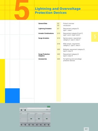
  • 1. 5/1 5 Lightning and Overvoltage Protection Devices General Data 5/2 Product overview 5/3 Introduction Lightning Arresters 5/7 Requirement category B, type 1, class I Arrester Combinations 5/10 Requirement category B and C, type 1 and 2, class I and II Surge Arresters 5/13 Narrow version, requirement category C, type 2, class II 5/16 Wide version, requirement category C, type 2, class II 5/20 Multipole, requirement category D, type 3, class III Surge Protection Adapters 5/22 Requirement category D, type 3, class III Accessories 5/25 For lightning and overvoltage protection devices
  • 2. Lightning and Overvoltage Protection Devices General Data Product overview 5/2 Siemens ET B1 T · 2007 ■Overview 1 MWmodular width 18 mm Lightning arresters – requirement category B, type 1, class I • Plug-in protective blocks • TN-C, TN-S and TT systems • Rated arrester voltage Uc 350 V AC • Lightning current 50 ... 100 kA • All versions with remote indication contact • Installation location: Main distribution board, upstream or downstream from the counter Arrester combinations– requirement category B and C, type 1 and 2, class I and II • Plug-in protective blocks • TN-C, TN-S and TT systems • Rated arrester voltage Uc 350 V AC • Lightning current 50 ... 100 kA • All versions with remote indication contact • Installation location: Main distribution board Surge arresters, narrow version – requirement category C, type 2, class II • Plug-in protective blocks • 2, 3 and 4-pole (TN-C, TN-S and TT systems) • Rated arrester voltage Uc 350 V AC • Rated discharge current 20 kA • Discharge surge current 40 kA • Version without or with remote indication contact • Installation location: Sub-distribution board • Mounting width 12 mm/pole Surge arresters, wide version – requirement category C, type 2, class II • Plug-in protective blocks or compact version • 1, 2, 3 and 4-pole (TN-C, TN-S and TT systems) • Rated arrester voltage Uc 350 V AC • Rated discharge current 20 kA • Discharge surge current 40 kA • Version without or with remote indication contact • Installation location: Sub-distribution board • Mounting width 18 mm/pole (1 MW/pole) Surge arresters – requirement category D, type 3, class III • Plug-in protective blocks • For 1-phase and 3-phase systems • Rated voltage - 1-phase AC/DC 24 V, 60 V, 120 V, 230 V - 3-phase system AC 230/400 V • Monitoring device • Installation location: As close as possible upstream from the terminal equipment Surge protection adapters – socket outlets, socket outlet adapters and combination protective devices • Can be plugged into 5 socket outlets • Status display • Permanent thermal monitoring of the protection circuit Accessories • Male connectors for lightning and surge arresters • Through-type terminals • Busbars
  • 3. Lightning and Overvoltage Protection Devices General Data Introduction 5/3Siemens ET B1 T · 2007 1 2 3 4 5 6 7 8 9 10 11 12 13 14 15 16 17 ■Overview Introduction to lightning and overvoltage protection Overvoltage destroys a considerable number of electrical and electronic devices and units. And the damage is not limited to just industrial and commercial facilities. Building management systems as well as household appliances for daily use are also affected. Without effective protection against overvoltage there is a real risk of costly repairs or replacement purchases due to the dam- age done to equipment. Listed below are units from various sectors which have sensitive electronic circuitry and are frequently destroyed by overvoltage. Clearly, protective measures for preventing overvoltage-related damage are just as important to private households as for the commercial and industrial sectors. An effective overvoltage pro- tection concept for building management systems covers power supply, telephone, aerial/reception, data processing and control systems. What is important is that all the cables connected to a device are linked to a suitable surge arrester. Nearly all devices have a power supply. A television set, for example, also needs a reception signal which is supplied over an aerial cable. And re- gardless of whether the signal comes from an aerial or a wide band cable, both the aerial input and power supply to the televi- sion set should be protected. The need for such consistent all- round protection applies equally to all other devices and units. Building management systems and industry • Heating controls • Outdoor lighting • Shutter controls • Garage door actuators • Central I&C • Air conditioning • Alarm systems • Fire alarms • Video surveillance • Process computers Office equipment • Computers • Printers • Telecommunication systems • Fax machines • Copying machines Private households • Dishwashers • Automatic washing machines • Clothes dryers • Coffee-makers • Radio alarm clocks • Refrigerators • Deep-freezers • Microwave ovens • Electric cookers • Telephone systems Hobbies and leisure • Television sets • Aerial amplifiers • Video recorders • DVD players • Hifi systems • Computers • Electrical musical instruments • CB radio systems In relation to the total value of the equipment concerned, the cost of installing suitable protective devices usually pays for itself when just a single unit of electrical equipment is saved just once from destruction . Provided the performance parameters are not exceeded, surge suppressors work many times, thus increasing the benefits for the user several-fold. The comprehensive surge protection concept Fundamentals Transient overvoltage results from lightning discharges, switch- ing operations in electrical circuits and electrostatic discharges. Without the protection provided by lightning arresters and over- voltage protection equipment, even the robustly constructed low-voltage supply systems of buildings or industrial plants are unable to cope with a lightning discharge. The overvoltage occurs only very briefly for millionths of a second. Nevertheless, the mostly very high voltages involved are capable of destroying electronic circuitry or the insulation between the conductors on printed circuit-boards. And even if an electrical or electronic device has passed the voltage withstand test according to IEC 100045, as required for being awarded the CE symbol, it is still not in a position to withstand unscathed all environmental influences with regard to electromagnetic compatibility (EMC). To prevent the destruction of electrical equipment by overvolt- age, all endangered interfaces such as signal inputs and power supplies must be connected to overvoltage protection equip- ment. What is needed, depending on the case of application, are components such as spark gaps, gas-filled surge arresters, varistors and suppressor diodes, which because of the differ- ences in their arresting and limiting specifications are arranged singly or as combinations in a protection circuit. The following damage can be caused by overvoltage Overvoltage endangers and destroys a considerable number of electrical and electronic installations. In the last few years there has been a sharp increase in the frequency of incidents and the total costs of the damage incurred. The statistics published by property insurance companies have a clear tale to tell. Damage to devices and their destruction occur all the more often when devices need to be in permanent standby. Repairs and replacement purchases are not the only expense factor, however. Costs also arise through not being able to use the affected system components and possibly even through loss of software and data. The damage profiles generally cover everything from destroyed cables, printed circuit-boards and switching devices to substantial mechanical destruction of the building installations. This damage can be reliably prevented by lightning arresters, surge suppressors and arrester combina- tions.
  • 4. Lightning and Overvoltage Protection Devices General Data Introduction 5/4 Siemens ET B1 T · 2007 Lightning and overvoltage protection – WHY? Powerful information systems form the backbone of our modern industrial society. A fault or the failure of these types of systems can have far-reaching consequences. These can even cause service and industry companies to go bankrupt. The cause of faults are many and electromagnetic influences play a major role. In a highly technical, electromagnetic environ- ment, it is not advisable to simply wait for the mutual influencing of electrical and electronic devices and systems and then pay good money to eliminate the resulting problems. Rather it is es- sential to plan and take preventative measures that reduce the risk of influences, faults and destruction. In spite of all this, the damage and loss statistics of electronic in- surance companies are extremely worrying: More than a quarter of all claims are as a result of overvoltages due to electromag- netic influences. Source: The causes of damage to electronics in 2001, analysis of 7370 claims Württembergische Versicherungs AG. Causes of overvoltage Depending on their cause, overvoltages are divided into two cat- egories: • LEMP (Lightning ElectroMagnetic Pulse) – overvoltages, caused by atmospheric influences (e.g. direct lightning strikes, electromagnetic lightning fields). • SEMP (Switching ElectroMagnetic Pulse) – overvoltages caused by switching operations (e.g. disconnection of short- circuits, normal switching of loads). Overvoltages that are the result of thunderstorms are caused by direct/close-up or remote strikes (see diagram on page 5/5). Direct or close-up strikes are lightning strikes to the lightning protection system of a building, its immediate proximity or to the electrical conductive systems of a building (e.g. l.v. power sup- ply, TC and control lines). The resulting surge currents and volt- ages are a particular threat to the system to be protected due to their amplitude and power. In the case of direct or close-up lightning strikes, the overvoltag- es (see diagram on page 5/5) are caused by the voltage drop at the surge grounding resistance and the resulting increase in potential of the building, compared to the distant environment. This represents the greatest possible loading of an electrical plant in buildings. The characteristic parameters of the surge current (peak value, rate of current rise, charge content, specific energy) can be de- scribed using the surge current waveform 10/350 µs (see dia- gram: examples of impulse test currents). These are defined in the international, European and national standards as test cur- rent for components and devices for protection in the event of direct strikes. In addition to the voltage drop at the surge grounding resis- tance, overvoltages also occur in electrical building installations and the connected systems and devices, due to the induction effect of the electromagnetic lightning field (see diagram on page 5/5: Example 1b). The energy of these induced overvoltages and the resulting pulse currents is considerably less than that of a direct lightning impulse current and is therefore only described with surge cur- rent wave 8/20 µs (see diagram: Examples of impulse test currents). Components and devices that do not carry currents from direct lightning strikes are therefore checked using surge currents 8/20 µs. Examples of impulse test currents The protection concept Remote strikes are lightning strikes at a greater distance from the objects to be protected, lightning strikes in the medium- voltage overhead system or the immediate proximity thereof, or lightning discharges from cloud to cloud (see diagram on page 5/5: Cases 2a, 2b and 2c). At the same time as these in- duced overvoltages, the effects of remote strikes on the electri- cal system of a building are controlled through devices and components, the dimensions of which correspond to surge cur- rent wave 8/20 µs. The causes of overvoltages due to switching operations in- clude the following: • Switching off of inductive loads (e.g. transformers, reactors, motors), • Ignition and interruption of electric arcs (e.g. arc-welding device), • Tripping of fuses. The effects of switching operations in the electrical installation of a building are simulated for testing purposes with surge currents of waveform 8/20 µs. To ensure the continuous availability of complex power and in- formation systems, even in the event of direct lightning strikes, further measures for overvoltage protection of electrical and electronic systems are required as well as a building lightning protection system. It is important to take all the causes of over- voltages into account. For this purpose, the lightning protection zone concept is used as described in IEC 62305-4 (DIN V VDE V 0185-4) (see diagram on page 5/6). The building is divided into zones of different danger levels. Using these zones, it is possible to determine the devices and components required for the lightning and overvoltage protection. 23,7 % 15,4 % 22,9 % 5,6 %0,8 % I2_11531a 27,1 % 4,6 % Fire Elementary Overvoltages (Lightning discharges and Switching operations) Other Negligence Water Theft Vandalism s [kA] 0 0 20 200 350400 600 800 1000 [ ] I2_11532a 25 50 75 100 8 1 2 4 1 2 s[ ] Q [As] W/R [J/ ] 100 10/350 50 2,5 × 10⁶ 8 8/20 0,1 0,4 × 10³ max [kA] Waveform Impulse test current for lightning arresters Impulse test current for surge arresters
  • 5. Lightning and Overvoltage Protection Devices General Data Introduction 5/5Siemens ET B1 T · 2007 1 2 3 4 5 6 7 8 9 10 11 12 13 14 15 16 17 An EMC-oriented lightning protection zone concept should also include external lightning protection (with air terminals, arrest- ers, grounding), equipotential bonding, room insulation and overvoltage protection for power and information systems. For the definition of lightning protection zones (LPZ), please use the specifications made in the table "Definition of lightning protection zones". Definition of lightning protection zones According to the demands and loads made on overvoltage pro- tection devices with regard to their installation site, these are di- vided into lightning arresters, surge arresters and arrester com- binations. The highest demands with regard to discharge capacity are made on lightning current and arrester combinations, which im- plement the transition from lightning protection zone LPZ 0A to LPZ 1 or LPZ 0A to LPZ 2. These surge arresters must be able to carry lightning partial currents of waveform 10/350 µs several times and thus prevent these destructive currents from penetrat- ing the electrical installation of a building. At the transition of lightning protection zone LPZ 0B to LPZ 1 the downstream light- ning arrester at the transition area of lightning protection zones LPZ 1 auf LPZ 2 and higher, surge arresters are installed to pro- tect against overvoltages. It is their task to further attenuate the remaining extent of the upstream protection level and restrict the overvoltages in the system, whether they are induced or self- generated. The lightning and overvoltage protective measures at the bor- ders of the lightning protection zones apply in equal measure to the energy and information system. The holistic approach of the measures described in the EMC-oriented lightning protection zone concept means it is possible to achieve permanent plant availability of a modern infrastructure. Causes for overvoltages during lightning discharges Lightning protection zones Description LPZ 0A Zone where objects are exposed to direct lightning strikes and must therefore carry the whole lightning current. The undamped electromagnetic field occurs in this case. LPZ 0B Zone where objects are not exposed to direct lightning strikes but where the undamped electromagnetic field still occurs. LPZ 1 Zone where objects are not exposed to direct lightning strikes and in which the currents are reduced compared to Zone 0A. In this zone, the electromagnetic field may be damped, depending on the insulation measures imple- mented. LPZ 2, LPZ 3 If a significant reduction in the conducted currents and/ or the electromagnetic field is required, subsequent zones must be set up. The demand on these zones must be geared towards the required environment zones of the system to be protected. I 2 _ 1 0 7 8 3 R s t 2 b 1 2 a 2 c 2 0 k V L 1 L 2 L 3 P E N 1 1 a 1 b 2 a 2 b 2 c 1 b 1 a D i r e c t / c l o s e - u p s t r i k e Strike in outer lightning protection, Process framework (in industrial plants), Cables, etc. Voltage drop at surge grounding resistance R Induced voltage in loops I T s y s t e m P o w e r s y s t e m st R e m o t e s t r i k e : Strike in medium- voltage overhead lines Overvoltage transformer waves on overhead lines, as a result of cloud-cloud lightning strikes Fields of lightning channel
  • 6. Lightning and Overvoltage Protection Devices General Data Introduction 5/6 Siemens ET B1 T · 2007 EMC-oriented lightning protection zone concept M A B B L E M P L E M P L E M P B S E M P I2_11533 R o o m i n s u l a t i o n V e n t i l a t i o n T e r m i n a l P o w e r - e n g i n e e r i n g s y s t e m I T s y s t e m L i g h t n i n g p r o t e c t i o n e q u i p o t e n t i a l b o n d i n g L i g h t n i n g c o n d u c t o r L o c a l e q u i p o t e n t i a l b o n d i n g S u r g e a r r e s t e r L P Z 0 L P Z 1 L P Z 2 L P Z 1 L P Z 0 L P Z 0 L P Z 3 L P Z 2 L P Z 0
  • 7. Lightning and Overvoltage Protection Devices Lightning Arresters Requirement category B, type 1, class I 5/7Siemens ET B1 T · 2007 1 2 3 4 5 6 7 8 9 10 11 12 13 14 15 16 17 ■Benefits • Type 1 lightning arresters do not require decoupling reactors to be fitted in the plant. This simplifies plant configuration and reduces space requirements. No time is wasted on planning the installation of decoupling reactors. This also considerably cuts costs. • The rated arrester voltage is a uniform 350 V AC. This in- creases safety in systems with extended voltage overshoots. • All lightning arresters are fitted with a mechanical fault indica- tion, which does not require an extra power supply. This means they can be installed in the precounter area, where electrical plants can be protected particularly effectively. • The protective modules are plug-in versions. No mounting work required when replacing the protective modules. When taking insulation measurements, the protective modules are simply removed, no need to disconnect the power supply. • All type 1 lightning arresters are fitted with a remote indication contact, which is inserted in the device and does not require any further space. A remote signaling is always possible, even in the event of a power failure. ■Application • Type 1 lightning arresters include the system cables in the equipotential bonding, which protects the low-voltage systems against the overvoltages and high surge currents that can be triggered by direct or indirect lightning strikes. • The protection level is lowered to 1.5 kV by the lightning ar- rester, which reduces the load on the plant if a lightning strike is discharged. • The lightning arresters are enclosed and are suitable for installation in the precounter area. • Tested by wave-shaped lightning impulse, 25/100 kA with waveform 10/350 µs. ■Technical specifications Design Lightning arresters Order No. 5SD7 412-1 5SD7 413-1 5SD7 414-1 Approvals KEMA (available soon) Requirement category B to E DIN VDE 06754-6; SPD class I according to IEC 61643-11; SPD type 1 according to EN 61643-1 Rated voltage UN V AC 230/400 230/400 230/400 Rated arrester voltage Uc • L/N, N/PE, L/PEN V AC 350 350 350 Lightning impulse current Iimp (10/350 µs) • L/N or L/PEN, 1-pole/3-pole kA 25/100 25/75 25/100 • N/PE kA 100 -- 100 Rated discharge surge current In (8/20 µs) • L/N or L/PEN, 1-pole/3-pole kA 25/100 25/75 25/100 • N/PE kA 100 -- 100 Protection level Up • L/N, N/PE, L/PEN kV ≤1.5 ≤1.5 ≤1.5 Follow current discharge capacity Ifi (AC) • L/N or L/PEN kA 50 50 50 • N/PE A 100 -- 100 Response time tA • L/N or L/PEN ns ≤100 ≤100 ≤100 • L-(N)-PE ns ≤100 -- ≤100 Max. required back-up protection A 315 gL/gG 315 gL/gG 315 gL/gG Short-circuit strength at max. back-up protection kArms 50 50 50 TOV voltage UT • L/N V/s 415/5 415/5 415/5 • N/PE V/ms 1200/200 -- 1200/200 Temperature range °C -40 ... +80 Degree of protection IP20 Conductor cross-section • Finely stranded mm2 0.5 ... 25 • Solid mm2 0.5 ... 35 Mounting width according to DIN 43880 MW 4 6 8 Remote signaling yes Contact type Floating CO contact (plug-in) Operational voltage, max. V AC 250 V DC 125 Operational current, max. • Resistive/inductive load AC 1 A/1 A • Resistive/inductive load DC 0.2 A/30 mA Conductor cross-section • Finely stranded/solid mm2 1.5/1.5
  • 8. Lightning and Overvoltage Protection Devices Lightning Arresters Requirement category B, type 1, class I 5/8 Siemens ET B1 T · 2007 ■Selection and ordering data ■Dimensional drawings 2-pole 5SD7 412-1 3-pole 5SD7 413-1 Dis- charge capacity MW Order No. Weight 1 unit approx. PS*/ P. unit kA kg Unit(s) Lightning arresters 2-pole for TT and TN-S systems 100 4 5SD7 412-1 0.732 1 3-pole for TN-C systems 75 6 5SD7 413-1 0.909 1 4-pole for TT and TN-S systems 100 8 5SD7 414-1 1.310 1 I2_12719 45 90 99 43,56,772 64 RS I2_12720 45 90 99 43,56,7108 64 RS * You can order this quantity or a multiple thereof.
  • 9. Lightning and Overvoltage Protection Devices Lightning Arresters Requirement category B, type 1, class I 5/9Siemens ET B1 T · 2007 1 2 3 4 5 6 7 8 9 10 11 12 13 14 15 16 17 4-pole 5SD7 414-1 ■Schematics 2-pole 5SD7 412-1 3-pole 5SD7 413-1 4-pole 5SD7 414-1 I2_12721 45 90 99 43,56,7144 64 RS PE L1 N I2_12565 12 14 11 RS L1 L2 L3 PEN I2_12566 12 14 11 RS PE L1 L2 L3 N I2_12567 12 14 11 RS
  • 10. Lightning and Overvoltage Protection Devices Arrester Combinations Requirement category B and C, type 1 and 2, class I and II 5/10 Siemens ET B1 T · 2007 ■Benefits • Type 1 and 2 arrester combinations do not require decoupling reactors to be fitted in the plant. This simplifies plant configu- ration and reduces space requirements. No time is wasted on planning the installation of decoupling reactors. This also con- siderably cuts costs. • The rated arrester voltage is a uniform 350 V AC. This increases safety in systems with longer voltage overshoots. • All arrester combinations are fitted with a mechanical fault in- dication, which does not require an extra power supply. • The protective modules are plug-in versions. No mounting work required when replacing the protective modules. When taking insulation measurements, the protective modules are simply removed, no need to disconnect the combination arrester from the power supply. • The same type 2, class II overvoltage protective modules are used as for the slim version of the surge arresters (5SD7 42.). This simplifies stock-keeping. • All arrester combinations are fitted with a remote indication contact, which is inserted in the device and does not require any further space. A remote signaling is always possible, even in the event of a power failure. ■Application • Type 1 and 2 arrester combinations include the system cables in the equipotential bonding, which protects the low-voltage systems against the overvoltages and high currents that can be triggered by direct lightning strikes. • The protection level is lowered to 1.5 kV by the arrester com- binations, which reduces the load on the plant if a lightning strike is discharged. • Tested by wave-shaped lightning impulse, 25/100 kA with waveform 10/350 µs. • A thermal isolating arrester disconnector offers a high degree of protection against overload during runtime. ■Technical specifications Design Arrester combinations Order No. 5SD7 442-1 5SD7 443-1 5SD7 444-1 Approvals KEMA (available soon) Requirement category B to E DIN VDE 06754-6; SPD class I according to IEC 61643-11; SPD type 1 according to EN 61643-1 Rated voltage UN V AC 230/400 230/400 230/400 Rated arrester voltage Uc • L/N, N/PE, L/PEN V AC 350 350 350 Lightning impulse current Iimp (10/350 µs) • L/N or L/PEN, 1-pole/3-pole kA 25/100 25/75 25/100 • N/PE kA 100 -- 100 Rated discharge surge current In (8/20 µs) • L/N or L/PEN, 1-pole/3-pole kA 25/100 25/75 25/100 • N/PE kA 100 -- 100 Protection level Up • L/N, N/PE, L/PEN kV ≤1.5 ≤1.5 ≤1.5 Follow current discharge capacity Ifi (AC) • L/N or L/PEN kA 25 25 25 • N/PE A 100 -- 100 Response time tA • L/N or L/PEN ns ≤100 ≤100 ≤100 • L-(N)-PE ns ≤100 -- ≤100 Max. required back-up protection A 315 gL/gG 315 gL/gG 315 gL/gG Short-circuit strength at max. back-up protection kArms 50 50 50 TOV voltage UT • L/N V/ms 350/5 350/5 350/5 • N/PE V/ms 1200/200 -- 1200/200 Temperature range °C -40 ... +80 Degree of protection IP20 Conductor cross-section • Finely stranded mm2 0.5 ... 25 • Solid mm2 0.5 ... 35 Mounting width according to DIN 43880 MW 4 6 8 Visual function/fault indication yes Remote signaling yes Contact type Floating CO contact (plug-in) Operational voltage, max. V AC 250 V DC 125 Operational current, max. • Resistive/inductive load AC 1 A/1 A • Resistive/inductive load DC 0.2 A/30 mA Conductor cross-section • Finely stranded/solid mm2 1.5/1.5
  • 11. Lightning and Overvoltage Protection Devices Arrester Combinations Requirement category B and C, type 1 and 2, class I and II 5/11Siemens ET B1 T · 2007 1 2 3 4 5 6 7 8 9 10 11 12 13 14 15 16 17 ■Selection and ordering data ■Dimensional drawings 2-pole 5SD7 442-1 3-pole 5SD7 443-1 Dis- charge capacity MW Order No. Weight 1 unit approx. PS*/ P. unit kA kg Unit(s) Arrester combinations 2-pole for TT and TN-S systems 100 4 5SD7 442-1 0.770 1 3-pole for TN-C systems 75 6 5SD7 443-1 1.040 1 4-pole for TT and TN-S systems 100 8 5SD7 444-1 1.430 1 I2_12696 45 90 99 43,56,772 64 RS I2_12697 45 90 99 43,56,7108 64 RS * You can order this quantity or a multiple thereof.
  • 12. Lightning and Overvoltage Protection Devices Arrester Combinations Requirement category B and C, type 1 and 2, class I and II 5/12 Siemens ET B1 T · 2007 4-pole 5SD7 444-1 ■Schematics 2-pole 5SD7 442-1 3-pole 5SD7 443-1 4-pole 5SD7 444-1 I2_12698 45 90 99 43,56,7144 64 RS PE L1 N I2_12568 12 14 11 RS L1 L2 L3 PEN I2_12569 12 14 11 RS PE L1 L2 L3 N I2_12570 12 14 11 RS
  • 13. Lightning and Overvoltage Protection Devices Surge Arresters Narrow version, requirement category C, type 2, class II 5/13Siemens ET B1 T · 2007 1 2 3 4 5 6 7 8 9 10 11 12 13 14 15 16 17 ■Benefits • Type 2 surge arresters do not require decoupling reactors to be fitted in the system. This simplifies plant configuration and reduces space requirements. No time is wasted on planning the installation of decoupling reactors. This considerably cuts costs. • The rated arrester voltage is a uniform 350 V AC. This increases safety in systems with extended voltage overshoots. • All type 2 surge arresters are fitted with a mechanical fault indication, which does not require an extra power supply. • The protective modules are plug-in versions. No mounting work required when replacing the protective modules. When taking insulation measurements, the protective modules are simply removed, no need to disconnect the surge arrester from the power supply. • The same protective modules are used as for combination arresters. This simplifies stock-keeping. • All type 2 surge arresters are available with a remote signaling contact, which is inserted in the device and does not require any further space. A remote signaling is always possible, even in the event of a power failure. The remote signaling signals a fault even if the protective module is not plugged in. • The protective module is only 12 mm wide and is an outstand- ing space-saving solution. ■Application • Type 2 surge arresters are used after type 1 lightning arresters in main distribution boards or sub-distribution boards and pro- tect low-voltage systems against overvoltages. • The type 2 surge arrester lowers the level of protection to 1.5 kV. • A thermal isolating arrester disconnector offers a high degree of protection against overload during runtime. ■Technical specifications Design Multipole surge arresters, 350 V without remote signaling with remote signaling Order No. 5SD7 422-0 5SD7 423-0 5SD7 424-0 5SD7 422-1 5SD7 423-1 5SD7 424-1 Approvals KEMA (available soon) Requirement category C to E DIN VDE 06754-6; SPD class II according to IEC 61643-11; SPD type 2 according to EN 61643-1 Rated voltage UN V AC 230/400 230/400 230/400 230/400 230/400 230/400 Rated arrester voltage Uc • L/N or L/PEN V AC 350 350 350 350 350 350 • N/PE V AC 264 -- 264 264 -- 264 Rated discharge surge current In (8/20 µs) • L/N or L/PEN, 1-pole/3-pole kA 20 20/60 20 20 20/60 20 • N/PE kA 20 -- 20 20 -- 20 Discharge surge current Imax (8/20 µs) • L/N or L/PEN, 1-pole/3-pole kA 40 40/120 40 40 40/120 40 • N/PE kA 40 -- 40 40 -- 40 Protection level Up • L/N or L/PEN kV ≤1.4 ≤1.4 ≤1.4 ≤1.4 ≤1.4 ≤1.4 • N/PE kV ≤1.5 -- ≤1.5 ≤1.5 -- ≤1.5 Response time tA • L/N ns ≤25 ≤25 ≤25 ≤25 ≤25 ≤25 • N/PE ns ≤100 -- ≤100 ≤100 -- ≤100 Max. required back-up protection A 125 gL/gG 125 gL/gG 125 gL/gG 125 gL/gG 125 gL/gG 125 gL/gG Short-circuit strength at max. back-up protection kArms 25 25 25 25 25 25 TOV voltage UT • L/N V/s 415/5 415/5 415/5 415/5 415/5 415/5 • N/PE V/ms 1200/200 -- 1200/200 1200/200 -- 1200/200 Temperature range °C -40 ... +80 Degree of protection IP20 Conductor cross-section • Finely stranded mm2 2.5 ... 16 • Solid mm2 0.5 ... 25 Mounting width according to DIN 43880 mm 26 38 50 26 38 50 Visual function/fault indication yes Remote signaling no no No yes yes yes Contact type -- -- -- Floating CO contact (plug-in) Operational voltage, max. V AC 250 V DC 125 Operational current, max. • Resistive/inductive load AC 1 A/1 A • Resistive/inductive load DC 0.2 A/30 mA Conductor cross-section • Finely stranded/solid mm2 1.5/1.5
  • 14. Lightning and Overvoltage Protection Devices Surge Arresters Narrow version, requirement category C, type 2, class II 5/14 Siemens ET B1 T · 2007 ■Selection and ordering data ■Dimensional drawings 2-pole 5SD7 422-. 5SD7 422-0 without RS (remote signaling) 3-pole 5SD7 423-. 5SD7 423-0 without RS (remote signaling) Discharge capacity rated value/max. Mounting width Order No. Weight 1 unit approx. PS*/ P. unit kA mm (MW) kg Unit(s) Surge arresters 5SD7 422-0 2-pole for TT and TN-S systems • Without remote signaling 20/40 24 (1 1/3) 5SD7 422-0 0.220 1 • With remote signaling 20/40 24 (1 1/3) 5SD7 422-1 0.227 1 5SD7 423-0 3-pole for TN-C systems • Without remote signaling 20/40 36 (2) 5SD7 423-0 0.320 1 • With remote signaling 20/40 36 (2) 5SD7 423-1 0.330 1 5SD7 424-1 4-pole for TT and TN-S systems • Without remote signaling 20/40 48 (2 2/3) 5SD7 424-0 0.408 1 • With remote signaling 20/40 48 (2 2/3) 5SD7 424-1 0.416 1 I2_12699 45 90 43,56,726 64 99 RS 45 90 43,56,738 64 I2_12700 99 RS * You can order this quantity or a multiple thereof.
  • 15. Lightning and Overvoltage Protection Devices Surge Arresters Narrow version, requirement category C, type 2, class II 5/15Siemens ET B1 T · 2007 1 2 3 4 5 6 7 8 9 10 11 12 13 14 15 16 17 4-pole 5SD7 424-. 5SD7 424-0 without RS (remote signaling) ■Schematics 2-pole 5SD7 422-. 5SD7 422-0 without RS (remote signaling) 3-pole 5SD7 423-. 5SD7 423-0 without RS (remote signaling) 4-pole 5SD7 424-. 5SD7 424-0 without RS (remote signaling) 45 90 43,56,750 64 I2_12701 99 RS L1PE N I2_12571 12 14 11 RS L3L2L1 PEN I2_12572 12 14 11 RS L3L2L1PE NI2_12573 12 14 11 RS
  • 16. Lightning and Overvoltage Protection Devices Surge Arresters Wide version, requirement category C, type 2, class II 5/16 Siemens ET B1 T · 2007 ■Benefits • Type 2 surge arresters do not require decoupling reactors to be fitted in the system. This simplifies plant configuration and reduces space requirements. No time is wasted on planning the installation of decoupling reactors. This considerably cuts costs. • The rated arrester voltage is a uniform 350 V AC. This increases safety in systems with extended voltage overshoots. • All type 2 surge arresters are fitted with a mechanical fault indication, which does not require an extra power supply. • The protective modules are plug-in versions. No mounting work required when replacing the protective modules. When taking insulation measurements, the protective modules are simply removed, no need to disconnect the surge arrester from the power supply. • Type 2 surge arresters are available with a remote signaling contact, which is inserted in the device and does not require any further space. A remote signaling is always possible, even in the event of a power failure. The remote signaling signals a fault even if the protective module is not plugged in. • The width of a protective module is 1 MW. This means that it can also be rail-mounted with a miniature circuit-breaker or RCCB. ■Application • Type 2 surge arresters are used after type 1 lightning arresters in main distribution boards or sub-distribution boards and pro- tect low-voltage systems against overvoltages. • The type 2 surge arrester lowers the level of protection to 1.5 kV. • A thermal isolating arrester disconnector offers a high degree of protection against overload during runtime. ■Technical specifications Design Single-pole surge arresters, wide version N/PE without remote signaling with remote signaling plug-in compact plug-in compact plug-in Order No. 5SD7 481-0 5SD7 466-0 5SD7 461-0 5SD7 466-1 5SD7 461-1 Approvals KEMA (available soon) Requirement category C to E DIN VDE 06754-6; SPD class II according to IEC 61643-11; SPD type 2 according to EN 61643-1 Rated voltage UN V AC 230 230 230 230 230 Rated arrester voltage Uc • L/N V AC -- 350 350 350 350 • N/PE V AC 260 -- -- -- -- Rated discharge surge current In (8/20 µs) • L/N kA -- 20 20 20 20 • N/PE kA 20 -- -- -- -- Discharge surge current Imax (8/20 µs) • L/N kA -- 40 40 40 40 • N/PE kA 40 -- -- -- -- Lightning test current Iimp (10/350 µs) kA 12 -- -- -- -- Protection level Up • L/N kV -- ≤1.4 ≤1.4 ≤1.4 ≤1.4 • N/PE kV ≤1 -- -- -- -- Response time tA • L/N ns -- ≤25 ≤25 ≤25 ≤25 • N/PE ns ≤100 -- -- -- -- Max. required back-up protection A 125 gL/gG 125 gL/gG 125 gL/gG 125 gL/gG 125 gL/gG Short-circuit strength at max. back-up protection kArms 25 25 25 25 25 TOV voltage UT • L/N V/s -- 415/5 415/5 415/5 415/5 Temperature range °C -40 ... +80 Degree of protection IP20 Conductor cross-section • Finely stranded mm2 0.5 ... 25 • Solid mm2 0.5 ... 35 Mounting width according to DIN 43880 MW 1 1 1 1 1 Visual function/fault indication yes Remote signaling no no no yes yes Contact type -- -- -- Floating CO contact (plug-in) Operational voltage, max. V AC 250 V DC 125 Operational current, max. • Resistive/inductive load AC 1 A/1 A • Resistive/inductive load DC 0.2 A/30 mA Conductor cross-section • Finely stranded/solid mm2 1.5/1.5
  • 17. Lightning and Overvoltage Protection Devices Surge Arresters Wide version, requirement category C, type 2, class II 5/17Siemens ET B1 T · 2007 1 2 3 4 5 6 7 8 9 10 11 12 13 14 15 16 17 Design Multipole surge arresters, wide version, plug-in without remote signaling contact with remote signaling contact 3-pole 4-pole 3-pole 4-pole Order No. 5SD7 463-0 5SD7 464-0 5SD7 463-1 5SD7 464-1 Approvals KEMA (available soon) Requirement category C to E DIN VDE 06754-6; SPD class II according to IEC 61643-11; SPD type 2 according to EN 61643-1 Rated voltage UN V AC 230/400 230/400 230/400 230/400 Rated arrester voltage Uc • L/N or L/PEN V AC 350 350 350 350 • N/PE V AC -- 264 -- 264 Rated discharge surge current In (8/20 µs) • L/N or L/PEN, 1-pole/3-pole kA 20/60 20 20/60 20 • N/PE kA -- 20 -- 20 Discharge surge current Imax (8/20 µs) • L/N or L/PEN, 1-pole/3-pole kA 40/120 40 40/120 40 • N/PE kA -- 40 -- 40 Protection level Up • L/N or L/PEN kV ≤1.4 ≤1.4 ≤1.4 ≤1.4 • N/PE kV -- ≤1.5 -- ≤1.5 Response time tA • L/N or L/PEN ns ≤25 ≤25 ≤25 ≤25 • N/PE ns -- ≤100 -- ≤100 Max. required back-up protection A 125 gL/gG 125 gL/gG 125 gL/gG 125 gL/gG Short-circuit strength at max. back-up protection kArms 25 25 25 25 TOV voltage UT • L/N or L/PEN V/s 415/5 415/5 415/5 415/5 • N/PE V/ms -- 1200/200 -- 1200/200 Temperature range °C -40 ... +80 Degree of protection IP20 Conductor cross-section • Finely stranded mm2 0.5 ... 25 • Solid mm2 0.5 ... 35 Mounting width according to DIN 43880 MW 3 4 3 4 Visual function/fault indication yes Remote signaling no no yes yes Contact type -- -- Floating CO contact (plug-in) Operational voltage, max. V AC 250 V DC 125 Operational current, max. • Resistive/inductive load AC 1 A/1 A • Resistive/inductive load DC 0.2 A/30 mA Conductor cross-section • Finely stranded/solid mm2 1.5/1.5
  • 18. Lightning and Overvoltage Protection Devices Surge Arresters Wide version, requirement category C, type 2, class II 5/18 Siemens ET B1 T · 2007 ■Selection and ordering data Discharge capacity rated value/max. MW Order No. Weight 1 unit approx. PS*/ P. unit kA kg Unit(s) Surge arresters, wide version 5SD7 466-1 1-pole, compact (non plug-in) • Without remote signaling 20/40 1 5SD7 466-0 0.114 1 • With remote signaling 20/40 1 5SD7 466-1 0.120 1 5SD7 461-1 1-pole, plug-in • Without remote signaling 20/40 1 5SD7 461-0 0.130 1 • With remote signaling 20/40 1 5SD7 461-1 0.134 1 N/PE, 1-pole, plug-in • Without remote signaling 20/40 1 5SD7 481-0 0.131 1 5SD7 463-1 3-pole, plug-in, 3+0 circuit for TN-C systems • Without remote signaling 20/40 3 5SD7 463-0 0.393 1 • With remote signaling 20/40 3 5SD7 463-1 0.403 1 5SD7 464-0 4-pole, plug-in, 3+1 circuit for TN-C and TN-S systems • Without remote signaling 20/40 4 5SD7 464-0 0.433 1 • With remote signaling 20/40 4 5SD7 464-1 0.443 1 * You can order this quantity or a multiple thereof.
  • 19. Lightning and Overvoltage Protection Devices Surge Arresters Wide version, requirement category C, type 2, class II 5/19Siemens ET B1 T · 2007 1 2 3 4 5 6 7 8 9 10 11 12 13 14 15 16 17 ■Dimensional drawings 5SD7 461-., 5SD7 481-0 5SD7 461-0 and 5SD7 481-0 without RS (remote signaling) 5SD7 463-. 5SD7 463-0 without RS (remote signaling) 5SD7 464-. 5SD7 464-0 without RS (remote signaling) 5SD7 466-. 5SD7 466-0 without RS (remote signaling) ■Schematics 5SD7 461-. 5SD7 461-0 without RS (remote signaling) 5SD7 463-. 5SD7 463-0 without RS (remote signaling) 5SD7 464-. 5SD7 466-. 5SD7 481-0 5SD7 466-0 without RS (remote signaling) I2_12703 45 90 99 43,56,718 64 RS I2_12704 45 90 99 43,56,754 64 RS I2_12705 45 90 99 43,56,772 64 RS I2_12702 45 90 99 43,56,718 64 RS (L/N) + L/N 12 11 14 ( ) I2_12621 RS L3L2L1 PEN I2_12572 12 14 11 RS L3L2L1PE N I2_12573 12 14 11 RS 5SD7 464-0 without RS (remote signaling) L1 PEN I2_12622 12 14 11 RS PE N I2_12623
  • 20. Lightning and Overvoltage Protection Devices Surge Arresters Multipole, requirement category D, type 3, class III 5/20 Siemens ET B1 T · 2007 ■Benefits • The protective modules are plug-in versions. No mounting work required when replacing the protective modules. • All type 3 surge arresters are fitted with a mechanical fault in- dication, which does not require an extra power supply. • In the event of a power failure, a remote signaling is output over an optocoupler with open collector output. ■Application • Type 3 surge arresters are installed after the type 2 surge arresters in sub-distribution boards close to the loads in single or multiphase systems and further limit the overvoltage in order to protect the connected loads. • Type 3 surge arresters in voltage versions 24, 60, 120 and 240 V can be used in AC and DC systems. ■Technical specifications Design Multipole surge arresters, plug-in 2-pole 4-pole Order No. 5SD7 432-1 5SD7 432-2 5SD7 432-3 5SD7 432-4 5SD7 434-1 Approvals KEMA Requirement category D to E DIN VDE 06754-6; SPD class III according to IEC 61643-11; SPD type 3 according to EN 61643-1 Rated voltage UN V AC 230 120 60 24 230/400 V DC 230 120 60 24 -- Rated current IN (at 30 °C) A 26 26 26 26 3 x 26 Rated arrester voltage Uc V AC 253 150 100 34 335 V DC 275 200 130 44 -- Rated discharge surge current In (8/20 µs) kA 3 2.5 2.5 1 1.5 Max. discharge surge current Imax (8/20 µs) kA 10 10 6.5 2 4.5 Combined surge Uoc kV 6 6 4 2 4 Protection level Up V ≤1500/≤600 ≤850/≤350 ≤700/≤250 ≤550/≤100 ≤1200 Response time tA ns ≤100 ≤100 ≤100 ≤100 ≤100 Max. required back-up protection A 25 gL/gG 25 gL/gG 25 gL/gG 25 gL/gG 25 gL/gG Temperature range °C -40 ... +85 Degree of protection IP20 Conductor cross-section • Finely stranded mm2 0.2 ... 4 • Solid mm2 0.2 ... 2.5 Mounting width according to DIN 43880 MW 1 1 1 1 2 Visual function/fault indication yes Remote signaling yes Contact type NC contacts Operational voltage, max. V 250 Operational current, max. A 3
  • 21. Lightning and Overvoltage Protection Devices Surge Arresters Multipole, requirement category D, type 3, class III 5/21Siemens ET B1 T · 2007 1 2 3 4 5 6 7 8 9 10 11 12 13 14 15 16 17 ■Selection and ordering data ■Dimensional drawings 2-pole 5SD7 432-. 4-pole 5SD7 434-1 ■Schematics 2-pole 5SD7 432-. Rated voltage Un MW Order No. Weight 1 unit approx. PS*/ P. unit kg Unit(s) Surge arresters, plug-in 5SD7 432-1 2-pole V AC, V DC with remote signaling 24 1 5SD7 432-4 0.027 1 60 1 5SD7 432-3 0.026 1 120 1 5SD7 432-2 0.081 1 230 1 5SD7 432-1 0.071 1 4-pole V AC with remote signaling 230/400 2 5SD7 434-1 0.056 1 I2_12706 45 71 90 45 296,718 7 9 11 58 8 1012 I2_12707 45 71 90 45 296,736 58 I2_12576 6 11 12 2 4 L 5 L 1 3 N PE N PE * You can order this quantity or a multiple thereof.
  • 22. Lightning and Overvoltage Protection Devices Surge Protection Adapters Requirement category D, type 3, class III 5/22 Siemens ET B1 T · 2007 ■Benefits • All type 3 surge protection adapters are fitted with an LED as a visual status and fault indication. • The protection circuit is continuously thermally monitored. This ensures constant safe operation for the operator. • The attractive design fits well into residential living spaces. ■Application • Type 3 surge protection adapters for insertion in a 5 socket outlet protect electronic loads against overvoltages from main power supplies. • However, overvoltages do not just reach loads over power cables. Telecommunication devices for TAE, ISDN/RDS and RJ12 connection, televisions or radios with aerial connection or satellite radio connection are all connected to a further power supply system which may also pass overvoltages on to devices. ■Technical specifications Design Surge protection adapters 5, line contactor TC analog/ TAE ISDN TV/radio TC analog/ RJ12 TV/SAT Order No. 5SD7 435-0 5SD7 435-2 5SD7 435-3 5SD7 435-5 5SD7 435-6 5SD7 435-7 Approvals VDE (available soon) Requirement category D to E DIN VDE 06754-6; SPD class III according to IEC 61643-11; SPD type 3 according to EN 61643-1 Line contactor Rated voltage UN (power supply) V AC 230 230 230 230 230 230 Rated current IN/ambient temperature A/°C 16/30 16/30 16/30 16/30 16/30 16/30 Rated arrester voltage Uc (power supply) • L/N V AC 275 275 275 275 275 275 • L-(N)-PE V AC 360 360 360 360 360 360 Rated discharge surge current In (8/20 µs) kA 3 3 3 3 3 3 Combined surge Uoc kV 4 4 4 4 4 4 Protection level Up • Core – Shield/Core – Ground kV ≤1.2 ≤1.2 ≤1.2 ≤1.2 ≤1.2 ≤1.2 Response time ta ns 25 25 25 215 25 25 Device protection Rated voltage UN (power supply) V AC 230 -- -- -- -- -- Rated current IN/ambient temperature A/°C 16/30 1.5/25 1.5/25 1.5/25 1.5/25 1.5/25 Rated arrester voltage Uc (power supply) • L/N V AC 275 -- -- -- -- -- V DC -- 200 6 72 200 72 • L-(N)-PE V AC 360 -- -- -- -- -- V DC -- 200 6 72 200 72 Rated discharge surge current In (8/20 µs) • Core – Shield kA 3 1 0.65 2.5 1 2.5 • Core – Ground kA 3 2.5 2.5 5 2.5 5 Combined surge Uoc kV 4 -- -- -- -- -- Protection level Up • Core – Shield/Core – Ground kV ≤1.2 ≤0.9 -- ≤0.7/≤0.9 ≤0.9 ≤0.7/≤0.9 Output voltage limit at 1 kV/µs • Core - Core V -- ≤360 ≤65 -- -- -- • Core – Shield V -- -- -- ≤700 -- ≤700 • Core – Ground V -- ≤450 ≤900 ≤900 -- ≤900 Residual current at In • Core – Core V -- ≤35 -- -- ≤35 -- • Core – Shield V ≤1200 -- -- ≤30 -- ≤30 • Core – Ground V ≤900 L-/N/PE ≤30 -- ≤30 ≤30 ≤30 Response time ta • Core – Core ns -- ≤25 ≤1 -- ≤25 -- • Core – Shield ns ≤25 -- -- ≤100 -- ≤100 • Core – Ground ns ≤100 L-/N/PE ≤100 ≤100 ≤100 ≤100 ≤100 Limit frequency fG (3 dB) -- -- -- ≥ 1.8 GHz -- ≥ 1.8 GHz • In 100 Ω system (typ.) -- -- 300 kHz -- -- -- • In 600 Ω system (typ.) -- 700 kHz -- -- 700 kHz -- General Temperature range °C -25 ... +75 Flammability category according to UL 94 V0 Degree of protection according to IEC 60529 IP20
  • 23. Lightning and Overvoltage Protection Devices Surge Protection Adapters Requirement category D, type 3, class III 5/23Siemens ET B1 T · 2007 1 2 3 4 5 6 7 8 9 10 11 12 13 14 15 16 17 ■Selection and ordering data Order No. Weight 1 unit approx. PS*/ P. unit kg Unit(s) Surge protection adapters for line contactor 5SD7 435-0 0.115 1 for telecommunication devices/TAE 5SD7 435-2 0.156 1 for ISDN/RDSI 5SD7 435-3 0.156 1 for TV/radio 5SD7 435-5 0.156 1 for telecommunication devices/RJ12 5SD7 435-6 0.144 1 for SAT installations 5SD7 435-7 0.156 1 * You can order this quantity or a multiple thereof.
  • 24. Lightning and Overvoltage Protection Devices Surge Protection Adapters Requirement category D, type 3, class III 5/24 Siemens ET B1 T · 2007 ■Dimensional drawings 5SD7 435-. ■Schematics 5SD7 435-0 5SD7 435-2 5SD7 435-3 5SD7 435-5, 5SD7 435-7 5SD7 435-6 I2_12708 52 63 42 36 103 79 LL + N N I2_12616 I2_12617 + La Lb La Lb PE N L + 5 4 6 3 I2_12618 + 5 b2 4 6 a2 b1 3 PE N L a1 + + I2_12619 PE N L +++ I2_12620a + La 3 4 2 5 Lb La Lb PE N L + + La Lb La Lb 3 4 2 5
  • 25. Lightning and Overvoltage Protection Devices Accessories For lightning and overvoltage protection devices 5/25Siemens ET B1 T · 2007 1 2 3 4 5 6 7 8 9 10 11 12 13 14 15 16 17 ■Technical specifications ■Selection and ordering data Design Through-type terminals Order No. 5SD7 490-1 Requirement category IEC 61643-1:11998-02, UL 1059, UL 486E Rated voltage Un V AC 230 Rated current In (at 30 °C) A 125 Rated arrester voltage Uc V 500 DC/AC Max. required back-up protection A 125 gL/gG Short-circuit strength at max. back-up protection kArms 25 Temperature range °C -40 ... +85 Degree of protection IP20 Conductor cross-section • Finely stranded mm2 0.5 ... 25 • Solid mm2 0.5 ... 35 Mounting width according to DIN 43880 MW 1 Order No. Weight 1 unit approx. PS*/ P. unit kg Unit(s) Through-type terminals for simple wiring in various wiring versions 5SD7 490-1 0.191 1 Connectors 5SD7 418-0 for 5SD7 41. lightning arresters, requirement category B, type 1, class I • Lightning arresters L/N Ifi 50 kAeff for 5SD7 41 lightning arresters. 5SD7 418-1 0.240 1 • Lightning arresters N/PE for 5SD7 41. lightning arresters and 5SD7 44. arrester combinations. 5SD7 418-0 0.240 1 5SD7 448-1 for 5SD7 44. arrester combinations, requirement category B, type 1, class I • Lightning arresters L/N Ifi 25 kAeff 5SD7 448-1 0.129 1/100 • Lightning arresters N/PE for 5SD7 41. lightning arresters and 5SD7 44. arrester combinations. 5SD7 418-0 0.240 1 5SD7 428-1 for 5SD7 42. surge arresters and 5SD7 44. arrester combi- nations, requirement category C, type 2, class II • Surge arresters L/N for 5SD7 42. surge arresters and 5SD7 44. arrester combinations. 5SD7 428-1 0.052 1 • Surge arresters N/PE 5SD7 428-0 0.049 1 5SD7 468-1 for 5SD7 46. surge arresters, requirement category C, type 2, class II • Surge arresters L/N 5SD7 468-1 0.051 1 • Surge arresters N/PE 5SD7 488-0 0.040 1 * You can order this quantity or a multiple thereof.
  • 26. Lightning and Overvoltage Protection Devices Accessories For lightning and overvoltage protection devices 5/26 Siemens ET B1 T · 2007 For busbars for lightning and overvoltage protection devices, see chapter "Busbars for modular installation devices" ■Dimensional drawings 5SD7 490-1 Order No. Weight 1 unit approx. PS*/ P. unit kg Unit(s) Connectors 5SD7 437-1 for surge arresters, wide version, 2-pole, 5SD7 432-., requirement category D, type 3, class III • Rated voltage Un = 230 V 5SD7 437-1 0.028 1 • Rated voltage Un = 120 V 5SD7 437-2 0.027 1 • Rated voltage Un = 60 V 5SD7 437-3 0.026 1 • Rated voltage Un = 24 V 5SD7 437-4 0.027 1 for surge arresters, wide version, 4-pole, 5SD7 434-1, requirement category D, type 3, class III 5SD7 438-1 0.162 1 I2_12709 45 90 43,56,718 64 * You can order this quantity or a multiple thereof.