
Recomendados
Mais conteúdo relacionado
Semelhante a DATA LINK CONTROL.pptx
Semelhante a DATA LINK CONTROL.pptx (20)
Mais de ODINARARCH
Mais de ODINARARCH (13)
Último
Último (20)
DATA LINK CONTROL.pptx
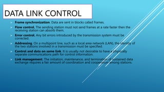
- 1. DATA LINK CONTROL Frame synchronization. Data are sent in blocks called frames. Flow control. The sending station must not send frames at a rate faster then the receiving station can absorb them. Error control. Any bit errors introduced by the transmission system must be corrected. Addressing. On a multipoint line, such as a local area network (LAN), the identity of the two stations involved in a transmission must be specified. Control and data on same link. It is usually not desirable to have a physically separate communications path for control information. Link management. The initiation, maintenance, and termination of sustained data exchange requires a fair amount of coordination and cooperation among stations.
- 2. FLOW CONTROL Flow control is the process of managing the rate data transmission between two nodes to prevent a fast sender from overwhelming a slow receiver. Flow control should be distinguished from congestion control, which is used for controlling the flow of data when congestion has actually occur.
- 4. STOP-AND-WAIT FLOW CONTROL Stop-and-wait flow control is the simplest form of flow control. In this method the message is broken into multiple frames, and the receiver indicates its readiness to receive a frame of data. The sender waits for a receipt acknowledgement (ACK) after every frame for a specified time (called a time out).
- 5. SLIDING-WINDOW FLOW CONTROL It allows the sender to send multiple frames before needing acknowledgements. Sender slides its window on receiving the acknowledgements for the sent frames. This allows the sender to send more frames.
- 6. ERROR DETECTION Error detection means to decide whether the received data is correct or not without having a copy of the original message. Error detection uses the concept of redundancy, which means adding extra bits for detecting errors at the destination.
- 7. ERROR CONTROL Error control refers to mechanisms to detect and correct errors that occur in the transmission of frames. Two types of errors: Lost frame. A frame fails to arrive at the other side. For example, a noise burst may damage a frame to the extent that the receiver is not aware that a frame has been transmitted. Damaged frame. A recognizable frame does arrive, but some of the bits are in error (have been altered during transmission).
- 8. The most common techniques for error control are based on some or all of the following ingredients: • Error detection. As discussed in the preceding section. • Positive acknowledgment. The destination returns a positive acknowledgment to successfully received, error-free frames. • Retransmission after timeout. The source retransmits a frame that has not been acknowledged a predetermined amount of time. • Negative acknowledgment and retransmission. The destination returns a negative to frames in which an error is detected. The source retransmits such frames.
- 9. AUTOMATIC REPEAT REQUEST (ARQ) The effect of ARQ is to turn an unreliable data link into reliable one. Three version of ARQ have been standardized: • Stop-and-wait ARQ • Go-back-N ARQ • Selective-reject ARQ
- 10. STOP-AND-WAIT ARQ Stop-and-wait ARQ is based on the stop-and-wait flow control technique. The source station transmits a single frame and then must await an acknowledgment (ACK). No other data frames can be sent until the destination station’s reply arrives at the source station.
- 11. GO-BACK-N ARQ The form of error control based on sliding-window flow control that is most commonly called go-back-N ARQ. In go-back-N ARQ, a station may send a series of frames sequentially numbered modulo some maximum value.
- 12. SELECTIVE-REJECT ARQ With selective-reject ARQ, the only frames retransmitted are those that receive a negative acknowledgment, in this case called SREJ, or that time-out.
- 13. HIGH-LEVEL DATA LINK CONTROL (HDLC) The most important data link control protocol is HDLC (ISO 33009, ISO 4335). Not only is HDLC widely used, but it is the basis for many other important data link control protocols, which use the same or similar formats and the same mechanisms as employed in HDLC.
- 14. The three station types are; • Primary station. Has the responsibility for controlling the operation of the link. Frames issued by the primary are called commands. • Secondary station. Operates under the control of the primary station. Frames issued by a secondary are called responses. • Combined station. Combines the features of primary and secondary. A combined station may issue both commands and responses. The two link configurations are: • Unbalanced configuration. Consists of one primary and one or more secondary stations and supports both full- duplex and half-duplex transmission. • Balanced configuration. Consists of two combined stations and supports both full-duplex and half-duplex transmission. The three data transfer modes are: • Normal response mode (NRM). Used with an unbalanced configuration. The primary may initiate data transfer to a secondary, but a secondary may only transmit data in response to a command from the primary. • Asynchronous balanced mode (ABM). Used with a balanced configuration. Either combined station may initiate transmission without receiving permission from the other combined station. • Asynchronous response mode (ARM). Used with an unbalanced configuration. The secondary may initiate transmission without explicit permission of the primary.
- 15. FRAME STRUCTURE HDLC uses synchronous transmission. All transmission are in the form of frames, and a single frame format suffices for all types of data and control exchanges.
- 16. Flag Fields Flag fields delimit the frame at both ends with unique pattern 01111110. A single flag may be used as the closing flag for one frame and the opening flag for the next. Address Field The address field identifies the secondary station that transmitted or is to receive the frame. This field is not needed for point-to-point links, but is always included for the sake of uniformity. Control Field HDLC defines three types of frames, each with a different control field format. Information frames frames (I-frames) carry the data to be transmitted for the user. Supervisory frames (S-frames) provide the ARQ mechanism when piggybacking is not used. Unnumbered frames (U-frames) provide supplemental link control functions. Information Field The information field is present only in I-frames and some U-frames. The field can contain any sequence of bits but must consist of an integral number of octets. Frame Check Sequence Field The frame check sequence (FCS) is an error-detecting code calculated from the the remaining bits of the frame, exclusive of flags.