Lexus Trouble Diagnostics
•
0 gostou•45 visualizações

Lexus Trouble Diagnostics Re-uploaded by OBDCodex

Recomendados
Recomendados
Mais conteúdo relacionado
Semelhante a Lexus Trouble Diagnostics
Semelhante a Lexus Trouble Diagnostics (20)
Mais de OBD Codex
Mais de OBD Codex (20)
Último
Último (20)
Lexus Trouble Diagnostics
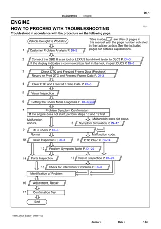
- 1. DI094–01 Vehicle Brought to Workshop Customer Problem Analysis P. DI–2 Problem Symptom Confirmation If the engine does not start, perform steps 10 and 12 first Connect the OBD II scan tool or LEXUS hand–held tester to DLC3 P. DI–3 If the display indicates a communication fault in the tool, inspect DLC3 P. DI–3 Check DTC and Freezed Frame Data (Precheck) Record or Print DTC and Freezed Frame Data P. DI–3 Clear DTC and Freezed Frame Data P. DI–3 Visual Inspection Setting the Check Mode Diagnosis P. DI–3 Symptom Simulation P. IN–17 DTC Chart P. DI–14 Problem Symptom Table P. DI–22 Circuit Inspection P. DI–23 Adjustment, Repair DTC Check P. DI–3 Titles inside are titles of pages in in the bottom portion. See the indicated pages for detailes explanations. this manual with the page number indicated Malfunction occurs. Malfunction does not occur. Parts Inspection Check for Intermittent Problems P. DI–3 Identification of Problem Confirmation Test End 1 2 3 4 5 6 7 10 8 9 11 12 13 15 14 16 Normal Malfunction code. 17 Basic Inspection P. DI–3 – DIAGNOSTICS ENGINE DI–1 153 Author: Date: 1997 LEXUS ES300 (RM511U) ENGINE HOW TO PROCEED WITH TROUBLESHOOTING Troubleshoot in accordance with the procedure on the following page.
- 2. DI095–01 ENGINE CONTROL SYSTEM Check Sheet Customer’s Name Driver’s Name Date Vehicle Brought in License No. Model and Model Year Frame No. Engine Model Odometer Reading km miles Problem Symptoms Engine does not Start Difficult to Start Poor Idling Poor Driveability Engine Stall Others Engine does not crank No initial combustion No complete combustion Engine cranks slowly Other Incorrect first idle Idling rpm is abnormal High ( rpm) Low ( rpm) Rough idling Other Hesitation Back fire Muffler explosion (after–fire) Surging Knocking Other Soon after starting After accelerator pedal depressed After accelerator pedal released During A/C operation Shifting from N to D Other Dates Problem Occurred Problem Frequency Condition When Problem Occurs Weather Engine Operation Engine Temp. Place Outdoor Temperature Constant Sometimes ( times per day/month) Once only Other Fine Cloudy Rainy Snowy Various/Other Hot Warm Cool Cold (approx. °F/ °C) Highway Suburbs Inner City Uphill Downhill Rough road Other Cold Warming up After Warming up Any temp. Other Starting Just after starting ( min.) Idling Racing Driving Constant speed Acceleration Deceleration A/C switch ON/OFF Other Condition of MIL Remains on Sometimes light up Does not light up Normal Malfunction code(s) (code ) Freezed frame data ( ) Normal Malfunction code(s) (code ) Freezed frame data ( ) Normal mode (Precheck) Check Mode DTC Inspection Inspector’s Name DI–2 – DIAGNOSTICS ENGINE 154 Author: Date: 1997 LEXUS ES300 (RM511U) CUSTOMER PROBLEM ANALYSIS CHECK
- 3. DI096–01 FI0534 S05335 LEXUS Hand–Held Tester DTC – DIAGNOSTICS ENGINE DI–3 155 Author: Date: 1997 LEXUS ES300 (RM511U) PRE–CHECK 1. DIAGNOSIS SYSTEM (a) Description When troubleshooting OBD II vehicles, the only differ- ence from the usual troubleshooting procedure is that you connect to the vehicle the OBD II scan tool complying with SAE J1978 or LEXUS hand–held tester, and read off vari- ous data output from the vehicle’s ECM. OBD II regulations require that the vehicle’s on–board computer lights up the Malfunction Indicator Lamp (MIL) on the instrument panel when the computer detects a malfunction in the computer itself or in drive system com- ponents which affect vehicle emissions. In addition to the MIL lighting up when a malfunction is detected, the appli- cable Diagnostic Trouble Codes (DTC) prescribed by SAE J2012 are recorded in the ECM memory (See page DI–14). If the malfunction does not reoccur in 3 trips, the MIL goes off but the DTC remain recorded in the ECM memory. To check the DTC, connect the OBD II scan tool or LEXUS hand–held tester to Data Link Connector 3 (DLC3) on the vehicle. The OBD II scan tool or LEXUS hand–held tester also enables you to erase the DTC and check freezed frame data and various forms of engine data (For operat- ing instructions, see the OBD II scan tool’s instruction book.). DTC include SAE controlled codes and manufacturer controlled codes. SAE controlled codes must be set as prescribed by the SAE, while manufacturer controlled codes can be set freely by the manufacturer within the prescribed limits (See DTC chart on page DI–14). The diagnosis system operates in normal mode during normal vehicle use. It also has a check mode for techni- cians to simulate malfunction symptoms and trouble- shoot. Most DTC use 2 trip detection logic* to prevent er- roneous detection, and ensure thorough malfunction detection. By switching the ECM to check mode when troubleshooting, the technician can cause the MIL to light up for a malfunction that is only detected once or momen- tarily (LEXUS hand–held tester only). (See page DI–14) *2 trip detection logic: When a logic malfunction is first de- tected, the malfunction is temporarily stored in the ECM memory. If the same malfunction is detected again during the second drive test, this second detection causes the MIL to light up. The 2 trip repeats the same mode a 2nd time (However, the IG switch must be turned OFF between the 1st trip and 2nd trip.).
- 4. N09214 DLC3 DI–4 – DIAGNOSTICS ENGINE 156 Author: Date: 1997 LEXUS ES300 (RM511U) Freeze frame data: Freeze frame data records the engine condition when a misfire (DTC P0300 ∼ P0306) or fuel trim malfunction (DTC P0171, P0172) or other malfunction (first malfunc- tion only), is detected. Because freeze frame data records the engine conditions (fuel system, calculator load, engine coolant tempera- ture, fuel trim, engine speed, vehicle speed, etc.) when the malfunction is detected, when troubleshooting it is useful for determining whether the vehicle was running or stopped, the engine warmed up or not, the air–fuel ratio lean or rich, etc. at the time of the malfunction. Priorities for troubleshooting: If troubleshooting priorities for multiple DTC are given in the applicable DTC chart, these should be followed. If no instructions are given troubleshoot DTC according to the following priorities. (1) DTC other than fuel trim malfunction (DTC P0171, P0172), EGR (DTC P0401, P0402) and misfire (DTC P0300 ∼ P0306). (2) Fuel trim malfunction (DTC P0171, P0172) and EGR (DTC P0401, P0402). (3) Misfire (DTC P0300 ∼ P0306). (b) Check the DLC3. The vehicle’s ECM uses ISO 9141–2 for communication. The terminal arrangement of DLC3 complies with SAE J1962 and matches the ISO 9141–2 format. Terminal No. Connection / Voltage or Resistance Condition 7 Bus Line / Pulse generation During transmission 4 Chassis Ground / ↔ Body Ground 1 Ω or less Always 5 Signal Ground / ↔ Body Ground 1 Ω or less Always 16 Battery Positive / ↔ Body Ground 9 ∼ 14 V Always HINT:If your display shows ”UNABLE TO CONNECT TO VE- HICLE” when you have connected the cable of the OBD II scan tool or LEXUS hand–held tester to DLC3, turned the ignition switch ON and operated the scan tool, there is a problem on the vehicle side or tool side. (1) If communication is normal when the tool is con- nected to another vehicle, inspect DLC3 on the orig- inal vehicle. (2) If communication is still not possible when the tool is connected to another vehicle, the problem is probably in the tool itself, so consult the Service De- partment listed in the tool’s instruction manual.
- 5. S05349 – DIAGNOSTICS ENGINE DI–5 157 Author: Date: 1997 LEXUS ES300 (RM511U) 2. INSPECT DIAGNOSIS (Normal Mode) (a) Check the MIL. (1) The MIL comes on when the ignition switch is turned ON and the engine is not running. HINT:If the MIL does not light up, troubleshoot the combination meter (See page BE–87). (2) When the engine started, the MIL should go off. If the lamp remains on, the diagnosis system has de- tected a malfunction or abnormality in the system. (b) Check the DTC. NOTICE:NOTICE (LEXUS hand–held tester only): When the diagnosis system is switched from normal mode to check mode, it erases all DTC and freezed frame data recorded in normal mode. So before switching modes, always check the DTC and freezed frame data, and note them down. (1) Prepare the OBD II scan tool (complying with SAE J 1978) or LEXUS hand–held tester. (2) Connect the OBD II scan tool or LEXUS hand–held tester to DLC3 at the lower center of the instrument panel. (3) Turn the ignition switch ON and push the OBD II scan tool or LEXUS hand–held tester switch ON. (4) Use the OBD II scan tool or LEXUS hand–held tes- ter to check the DTC and freezed frame data, note them down (For operating instructions, see the OBD II scan tool’s instruction book.). (5) See page DI–14 to confirm the details of the DTC. NOTICE:When simulating symptoms with an OBD II scan tool (excluding LEXUS hand–held tester) to check the DTC, use normal mode. For code on the DTC chart subject to ”2 trip detection logic”, turn the ignition switch OFF after the symptom is simulated the first time. Then repeat the simu- lation process again. When the problem has been simu- lated twice, the MIL lights up and the DTC are recorded in the ECM.
- 6. FI3605 Flashing ON OFF 0.13 Seconds DI–6 – DIAGNOSTICS ENGINE 158 Author: Date: 1997 LEXUS ES300 (RM511U) 3. INSPECT DIAGNOSIS (Check Mode) LEXUS hand–held tester only: Compared to the normal mode, the check mode has an in- creased sensitivity to detect malfunctions. Furthermore, the same diagnostic items which are detected in the normal mode can also be detected in the check mode. (a) Check the DTC. (1) Initial conditions. Battery positive voltage 11V or more Throttle valve fully closed Transmission in ”P” or ”N” position Air conditioning switched OFF (2) Turn ignition switch OFF. (3) Prepare the LEXUS hand–held tester. (4) Connect the LEXUS hand–held tester to DLC3 at the lower center of the instrument panel. (5) Turn the ignition switch ON and push the LEXUS hand–held tester switch ON. (6) Switch the LEXUS hand–held tester normal mode to check mode (Check that the MIL flashes.). (7) Start the engine (The MIL goes out after the engine start.). (8) Simulate the conditions of the malfunction de- scribed by the customer. NOTICE:Leave the ignition switch ON until you have checked the DTC, etc. (9) After simulating the malfunction conditions, use the LEXUS hand–held tester diagnosis selector to check the DTC and freezed frame data, etc. HINT:Take care not to turn the ignition switch OFF. Turning the ignition switch OFF switches the diagnosis system from check mode to normal mode, so all DTC, etc. are erased. (10) After checking the DTC, inspect the applicable cir- cuit. (b) Clear the DTC. The following actions will erase the DTC and freezed frame data. (1) Operating the OBD II scan tool (complying with SAE J1978) or LEXUS hand–held tester to erase the codes (See the OBD II scan tool’s instruction book for operating instructions.). (2) Disconnecting the battery terminals or EFI fuse. NOTICE:If the LEXUS hand–held tester switches the ECM from normal mode to check mode or vice–versa, or if the ignition switch is turned from ON to ACC or OFF during check mode, the DTC and freezed frame data will be erased.
- 7. – DIAGNOSTICS ENGINE DI–7 159 Author: Date: 1997 LEXUS ES300 (RM511U) 4. FAIL–SAFE CHART If any of the following codes is recorded, the ECM enters fail–safe mode. DTC No. Fail–Safe Operation Fail–Safe Deactivation Conditions P0100 Ignition timing fixed at 10° BTDC Returned to normal condition P0110 Intake air temp. is fixed at 20°C (68°F) Returned to normal condition P0115 Engine coolant temp. is fixed at 80°C (176°F) Returned to normal condition P0120 VTA is fixed at 0° The following condition must be repeated at least 2 times consecutively 0.1 V VTA 0.95 V P0135 P0141 P0155 The heater circuit in witch an abnormality is detected is turned off Ignition switch OFF P0325 P0330 Max. timing retardation Ignition switch OFF P1300 Fuel cut Returned to normal condition 5. CHECK FOR INTERMITTENT PROBLEMS LEXUS HAND–HELD TESTER only: By putting the vehicle’s ECM in check mode, 1 trip detection logic is possible instead of 2 trip detection logic and sensitivity to detect open circuits is increased. This makes it easier to detect intermittent problems. (a) Clear the DTC (See page DI–3). (b) Set the check mode (See page DI–3). (c) Perform a simulation test (See page IN–17). (d) Check the connector and terminal (See page IN–27). (e) Handle the connector (See page IN–27). 6. BASIC INSPECTION When the malfunction code is not confirmed in the DTC check, troubleshooting should be performed in the order for all possible circuits to be considered as the causes of the problems. In many cases, by carrying out the basic engine check shown in the following flow chart, the location causing the problem can be found quickly and efficiently. Therefore, use of this check is essential in engine troubleshooting. 1 Is battery positive voltage 11 V or more when engine is stopped ? NO Charge or replace battery. YES 2 Is engine cranked ? NO Proceed to page ST–18 and continue to troubleshoot. YES
- 8. P00495 Outside Inside DI–8 – DIAGNOSTICS ENGINE 160 Author: Date: 1997 LEXUS ES300 (RM511U) 3 Does engine start ? NO Go to step 7. YES 4 Check air filter. PREPARATION: Remove the air filter. CHECK: Visual check that the air filter is not dirty or excessive oily. HINT:If necessary, clean the filter with compressed air. First blow from inside thoroughly, then blow from outside of filter. NG Repair or replace. OK 5 Check engine idle speed. PREPARATION: (a) Warm up engine to normal operating temperature. (b) Switch off all accessories. (c) Switch off air conditioning. (d) Shift transmission into ”N” position. (e) Connect the OBD II scan tool or LEXUS hand–held tester to DLC3 on the vehicle. CHECK: Use CURRENT DATA to check the idle speed. OK: Idle speed: 650 ∼ 750 rpm NG Proceed to problem symptoms table on page DI–22. OK
- 9. A00209 DLC1 TE1 E1 SST DLC1 P12915 P12952 P20186 – DIAGNOSTICS ENGINE DI–9 161 Author: Date: 1997 LEXUS ES300 (RM511U) 6 Check ignition timing. PREPARATION: (a) Warm up engine to normal operating temperature. (b) Switch off all accessories. (c) Switch off air conditioning. (d) Shift transmission into ”N” position. (e) Keep the engine speed at idle. (f) Using SST, connect terminals TE1 and E1 of the DLC1. SST 09843 – 18020 (g) Using a timing light, connect the tester to check wire. CHECK: Check ignition timing. OK: Ignition timing: 10° BTDC at idle NG Proceed to page IG–1 and continue to troubleshoot. OK Proceed to problem symptoms table on page DI–22. 7 Check fuel pressure. PREPARATION: (a) Be sure that enough fuel is in the tank. (b) Connect the LEXUS hand–held tester to the DLC3. (c) Turn ignition switch ON and push LEXUS hand–held tes- ter main switch ON. (d) Use ACTIVE TEST mode to operate the fuel pump. (e) If you have no LEXUS hand–held tester, connect the pos- itive (+) and negative (–) leads from the battery to the fuel pump connector (See page SF–6). CHECK: Check that the pulsation damper screw rises up when the fuel pump operates. NG Proceed to page SF–6 and continue to troubleshoot. OK
- 10. P23917 DI–10 – DIAGNOSTICS ENGINE 162 Author: Date: 1997 LEXUS ES300 (RM511U) 8 Check for spark. PREPARATION: (a) Remove the ignition coil or disconnect the high–tension cord from spark plug. (b) Remove the spark plug. (c) Install the spark plug to the ignition coil or high–tension cord. (d) Disconnect the injector connector. (e) Hold the end about 12.5 mm (0.5 in.) from the ground. CHECK: Check if spark occurs while engine is being cranked. NOTICE:To prevent excess fuel being injected from the in- jectors during this test, don’t crank the engine for more than 5 ∼ 10 seconds at a time. OK: Spark jumps across electrode gap. NG Proceed to page IG–1 and continue to troubleshoot. OK Proceed to problem symptoms table on page DI–22.
- 11. – DIAGNOSTICS ENGINE DI–11 163 Author: Date: 1997 LEXUS ES300 (RM511U) 7. ENGINE OPERATING CONDITION NOTICE:The values given below for ”Normal Condition” are representative values, so a vehicle may still be normal even if its value from those listed here. So do not decide whether a part is faulty or not solely according to the ”Normal Condition” here. (a) CARB mandated signals. LEXUS hand–held tester display Measurement Item Normal Condition* FUEL SYS #1 Fuel System Bank 1 OPEN: Air–fuel ratio feedback stopped CLOSED: Air–fuel ratio feedback operating Idling after warming up: CLOSED FUEL SYS #2 Fuel System Bank 2 OPEN: Air–fuel ratio feedback stopped CLOSED: Air–fuel ratio feedback operating Idling after warming up: CLOSED CALC LOAD Calculator Load: Current intake air volume as a proportion of max. intake air volume Idling: 13.1 ∼ 18.7% Racing without load (2,500rpm): 11.7 ∼ 17.3% COOLANT TEMP. Engine Coolant Temp. Sensor Value After warming up: 80 ∼ 95°C (176 ∼ 203°F) SHORT FT #1 Short–term Fuel Trim Bank 1 0 ± 20% LONG FT #1 Long–term Fuel Trim Bank 1 0 ± 20% SHORT FT #2 Short–term Fuel Trim Bank 2 0 ± 20% LONG FT #2 Long–term Fuel Trim Bank 2 0 ± 20% ENGINE SPD Engine Speed Idling: 650 ∼ 750 rpm VEHICLE SPD Vehicle Speed Vehicle stopped: 0 km/h (0 mph) IGN ADVANCE Ignition Advance: Ignition Timing of Cylinder No. 1 Idling: BTDC 10 ∼ 25.0° INTAKE AIR Intake Air Temp. Sensor Value Equivalent to Ambient Temp. MAF Air Flow Rate Through Mass Air Flow Meter Idling: 3.3 ∼ 4.7 gm/sec. Racing without load (2,500 rpm): 10.4 ∼ 15.4 gm/sec. THROTTLE POS Voltage Output of Throttle Position Sensor Calculated as a percentage: 0 V → 0%, 5 V → 100% Throttle valve fully closed: 7 ∼ 11% Throttle valve fully open: 65 ∼ 75% O2S B1, S1 Voltage Output of Oxygen Sensor Bank 1, Sensor 1 Idling: 0.1 ∼ 0.9 V O2FT B1, S1 Oxygen Sensor Fuel Trim Bank 1, Sensor 1 (Same as SHORT FT #1) 0 ± 20% O2S B1, S2 Voltage Output of Oxygen Sensor Bank 1, Sensor 2 Driving 50 km/h (31 mph): 0.1 ∼ 0.9 V O2S B2, S1 Voltage Output of Oxygen Sensor Bank 2, Sensor 1 Idling: 0.1 ∼ 0.9 V O2FT B2, S1 Oxygen Sensor Fuel Trim Bank 2, Sensor 1 (Same as SHORT FT #2) 0 ± 20% ∗: If no conditions are specifically stated for ”ldling”, it means the shift lever is at N or P position, the A/C switch is OFF and all accessory switches are OFF.
- 12. DI–12 – DIAGNOSTICS ENGINE 164 Author: Date: 1997 LEXUS ES300 (RM511U) (b) LEXUS Enhanced Signals. LEXUS hand–held tester display Measurement Item Normal Condition* MISFIRE RPM Engine RPM for first misfire range Misfire 0: 0 rpm MISFIRE LOAD Engine load for first misfire range Misfire 0: 0 g/r INJECTOR Fuel injection time for cylinder No.1 Idling: 1.6 ∼ 2.9 ms IAC DUTY RATIO Intake Air Control Valve Duty Ratio Opening ratio rotary solenoid type IAC valve Idling: 27 ∼ 47 % STARTER SIG Starter Signal Cranking: ON CTP SIG Closed Throttle Position Signal Throttle Fully Closed: ON A/C SIG A/C Switch Signal A/C ON: ON PNP SW Park/Neutral Position Switch Signal P or N position: ON ELCTRCL LOAD SIG Electrical Load Signal Defogger switch ON: ON STOP LIGHT SW Stop Light Switch Signal Stop light switch ON: ON PS OIL PRESS SW Power Steering Oil Pressure Switch Signal Turn steering wheel: ON FC IDL Fuel Cut Idle: Fuel cut when throttle valve fully closed, during deceleration Fuel cut operating: ON FC TAU Fuel Cut TAU: Fuel cut during very light load Fuel cut operating: ON CYL#1 ∼ CYL#6 Abnormal revolution variation for each cylinder 0% IGNITION Total number of ignition for every 1,000 revolu- tions 0 ∼ 3,000 rpm EGRT GAS EGR Gas Temperature Sensor Value EGR not operating: Temperature between intake air temp. and engine coolant temp. INTAKE CTRL VSV Intake Air Control Valve VSV Signal VSV operating: ON EGR SYSTEM EGR system operating condition Idling: OFF A/C CUT SIG A/C Cut Signal A/C S/W OFF: ON FUEL PUMP Fuel Pump Signal Idling: ON EVAP (PURGE) VSV EVAP VSV Signal VSV operating: ON VAPOR PRESS VSV Vapor Pressure VSV Signal VSV operating: ON ∗: If no conditions are specifically stated for ”ldling”, it means the shift lever is at N or P position, the A/C switch is OFF and all accessory switches are OFF.
- 13. – DIAGNOSTICS ENGINE DI–13 165 Author: Date: 1997 LEXUS ES300 (RM511U) LEXUS hand–held tester display Measurement Item Normal Condition* TOTAL FT B1 Total Fuel Trim Bank 1: Average value for fuel trim system of bank 1 Idling: 0.8 ∼ 1.2 TOTAL FT B2 Total Fuel Trim Bank 1: Average value for fuel trim system of bank 2 Idling: 0.8 ∼ 1.2 O2 LR B1, S1 Oxygen Sensor Lean Rich Bank 1, Sensor 1 Re- sponse time for oxygen sensor output to switch from lean to rich Idling after warmed up: 0 ∼ 1,000 msec. O2 LR B2, S1 Oxygen Sensor Lean Rich Bank 2, Sensor 1 Re- sponse time for oxygen sensor output to switch from lean to rich Idling after warmed up: 0 ∼ 1,000 msec. O2 RL B1, S1 Oxygen Sensor Rich Lean Bank 1, Sensor 1 Response time for oxygen sensor output to switch from rich to lean Idling after warmed up: 0 ∼ 1,000 msec. O2 RL B2, S1 Oxygen Sensor Rich Lean Bank 2, Sensor 1 Response time for oxygen sensor output to switch from rich to lean Idling after warmed up: 0 ∼ 1,000 msec. ∗: If no conditions are specifically stated for ”ldling”, it means the shift lever is at N or P position, the A/C switch is OFF and all accessory switches are OFF.
- 14. DI097–01 DI–14 – DIAGNOSTICS ENGINE 166 Author: Date: 1997 LEXUS ES300 (RM511U) DIAGNOSTIC TROUBLE CODE CHART HINT:Parameters listed in the chart may not be exactly the same as your reading due to the type of instru- ment or other factors. If a malfunction code is displayed during the DTC check in check mode, check the circuit for that code listed in the table below. For details of each code, turn to the page referred to under the ’’See page ’’ for the respec- tive ’’DTC No.’’ in the DTC chart. DTC No. (See Page) Detection Item Trouble Area MIL* Memory P0100 (DI–23) Mass Air Flow Circuit Malfunction Open or short in mass air flow meter circuit Mass air flow meter ECM P0101 (DI–27) Mass Air Flow Circuit Range/Performance Problem Mass air flow meter P0110 (DI–28) Intake Air Temp. Circuit Malfunction Open or short in intake air temp. sensor circuit Intake air temp. sensor ECM P0115 (DI–33) Engine Coolant Temp. Circuit Malfunction Open or short in engine coolant temp. sensor circuit Engine coolant temp. sensor ECM P0116 (DI–37) Engine Coolant Temp. Circuit Range/Performance Problem Engine coolant temp. sensor Cooling system P0120 (DI–38) Throttle/Pedal Position Sensor/Switch ”A” Circuit Malfunction Open or short in throttle position sensor circuit Throttle position sensor ECM P0121 (DI–42) Throttle/Pedal Position Sensor/Switch ”A” Circuit Range/Performance Problem Throttle position sensor P0125 (DI–43) Insufficient Coolant Temp. for Closed Loop Fuel Control Open or short in heated oxygen sensor circuit Heated oxygen sensor P0130 (DI–46) Heated Oxygen Sensor Circuit Malfunction (Bank 1 Sensor 1) Heated oxygen sensor Fuel trim malfunction P0133 (DI–49) Heated Oxygen Sensor Circuit Slow Response (Bank 1 Sensor 1) Heated oxygen sensor P0135 (DI–50) Heated Oxygen Sensor Heater Circuit Malfunction (Bank 1 Sensor 1) Open or short in heater circuit of heated oxygen sensor Heated oxygen sensor ECM P0136 (DI–52) Heated Oxygen Sensor Circuit Malfunction (Bank 1 Sensor 2) Heated oxygen sensor P0141 (DI–50) Heated Oxygen Sensor Heater Circuit Malfunction (Bank 1 Sensor 2) Same as DTC No. P0135 P0150 (DI–46) Heated Oxygen Sensor Circuit Malfunction (Bank 2 Sensor 1) Same as DTC No. P0130 *: MIL lights up
- 15. – DIAGNOSTICS ENGINE DI–15 167 Author: Date: 1997 LEXUS ES300 (RM511U) DTC No. (See Page) Detection Item Trouble Area MIL* Memory P0153 (DI–49) Heated Oxygen Sensor Circuit Slow Response (Bank 2 Sensor 1) Same as DTC No. P0133 P0155 (DI–50) Heated Oxygen Sensor Heater Circuit Malfunction (Bank 2 Sensor 1) Same as DTC No. P0135 P0171 (DI–54) System too Lean (Fuel Trim) Air intake (hose loose) Fuel line pressure Injector blockage Heated oxygen sensor malfunction Mass air flow meter Engine coolant temp. sensor P0172 (DI–54) System too Rich (Fuel Trim) Fuel line pressure Injector leak, blockage Heated oxygen sensor malfunction Mass air flow meter Engine coolant temp. sensor P0300 (DI–57) Random/Multiple Cylinder Misfire Detected Ignition system I j t P0301 P0302 P0303 P0304 P0305 P0306 (DI–57) Misfire Detected – Cylinder 1 – Cylinder 2 – Cylinder 3 – Cylinder 4 – Cylinder 5 – Cylinder 6 Injector Fuel line pressure Compression pressure Valve clearance not to specification Valve timing Mass air flow meter Engine coolant temp. sensor *2 P0325 (DI–62) Knock Sensor 1 Circuit Malfunction Open or short in knock sensor 1 circuit Knock sensor 1 (looseness) ECM P0330 (DI–62) Knock Sensor 2 Circuit Malfunction Open or short in knock sensor 2 circuit Knock sensor 2 (looseness) ECM P0335 (DI–66) Crankshaft Position Sensor ”A” Circuit Malfunction Open or short in crankshaft position sensor circuit Crankshaft position sensor Starter ECM P0340 (DI–69) Camshaft Position Sensor Circuit Malfunction Open or short in camshaft position sensor circuit Camshaft position sensor Starter ECM P0401 (DI–71) Exhaust Gas Recirculation Flow Insufficient Detected EGR valve (stuck closed) Open or short in EGR gas temp. sensor circuit EGR gas temp. sensor Open in VSV circuit for EGR VSV for EGR Vacuum control valve Vacuum hose disconnected or blocked ECM *1: MIL lights up *2: MIL lights up or blinking
- 16. DI–16 – DIAGNOSTICS ENGINE 168 Author: Date: 1997 LEXUS ES300 (RM511U) DTC No. (See Page) Detection Item Trouble Area MIL* Memory P0402 (DI–81) Exhaust Gas Recirculation Flow Excessive Detected EGR valve stuck open VSV for EGR open malfunction Short in VSV circuit for EGR Open or short in EGR valve position sensor circuit EGR valve position sensor ECM P0420 (DI–84) Catalyst System Efficiency Below Threshold Three–way catalytic converter Open or short in heated oxygen sensor circuit Heated oxygen sensor *2 P0440 (DI–87) Evaporative Emission Control System Malfunction Vapor pressure sensor Fuel tank cap incorrectly installed Fuel tank cap cracked or damaged Vacuum hose cracked, holed, blocked, damaged or disconnected Hose or tube cracked, holed, damaged or insufficient seal Fuel tank cracked, holed or damaged Charcoal canister cracked, holed or damaged P0441 (DI–93) Evaporative Emission Control System Incorrect Purge Flow Open or short in VSV circuit for EVAP VSV for EVAP Open or short in vapor pressure sensor circuit Vapor pressure sensor Open or short in VSV circuit for vapor pressure sensor VSV for vapor pressure sensor Vacuum hose cracked, holed, blocked, damaged or disconnected Charcoal canister cracked, holed or damaged P0446 (DI–93) Evaporative Emission Control System Vent Control Malfunction Open or short in VSV circuit for EVAP VSV for EVAP Open or short in vapor pressure sensor circuit Vapor pressure sensor Open or short in VSV circuit for vapor pressure sensor VSV for vapor pressure sensor Vacuum hose cracked, holed, blocked, damaged or disconnected Charcoal canister cracked, holed or damaged P0450 (DI–104) Evaporative Emission Control System Pressure Sensor Malfunction Open or short in vapor pressure sensor circuit Vapor pressure sensor ECM P0500 (DI–106) Vehicle Speed Sensor Malfunction Open or short in speed signal circuit Open or short in speed sensor circuit for ABS Combination meter ECM ABS ECU P0505 (DI–109) Idle Control System Malfunction IAC valve is stuck or closed Open or short in IAC valve circuit Open or short in A/C signal circuit Air intake (hose loose) *1: MIL lights up *2: MIL lights up on U.S.A. and Canadian specification vehicles
- 17. – DIAGNOSTICS ENGINE DI–17 169 Author: Date: 1997 LEXUS ES300 (RM511U) DTC No. (See Page) Detection Item Trouble Area MIL* Memory P1300 (DI–112) Igniter Circuit Malfunction Open or short in IGF or IGT circuit from igniter to ECM Igniter ECM P1335 (DI–117) Crankshaft Position Sensor Circuit Malfunction (during engine running) Open or short in crankshaft position sensor circuit Crankshaft position sensor ECM – P1410 (DI–118) EGR Valve Position Sensor Circuit Malfunction Open or short in EGR valve position sensor circuit EGR valve position sensor ECM P1411 (DI–122) EGR Valve Position Sensor Circuit Range/Performance Problem EGR valve position sensor P1520 (DI–123) Stop Light Switch Signal Malfunction Short in stop light switch signal circuit Stop light switch ECM P1600 (DI–126) ECM BATT Malfunction Open in back up power source circuit ECM P1780 (DI–128) Park/Neutral Position Switch Malfunction Short in park/neutral position switch circuit Park/neutral position switch ECM *: – MIL does not light up MIL lights up
- 18. DI098–01 S06290 Engine Coolant Temp. Sensor Heated Oxygen Sensor (Bank 1 Sensor 2) VSV for EVAP VSV for ACIS Vapor Pressure Sensor Crankshaft Position Sensor Camshaft Position Sensor Heated Oxygen Sensor (Bank 1 Sensor 1) Heated Oxygen Sensor (Bank 2 Sensor 1) Park/Neutral Position Switch Knock Sensor 1 Knock Sensor 2 EGR Gas Temp. Sensor Injector DLC1 ECM EGR Valve Position Sensor VSV for EGR DLC3 VSV for Vapor Pressure Sensor IAC Valve Mass Air Flow Meter Igniter DI–18 – DIAGNOSTICS ENGINE 170 Author: Date: 1997 LEXUS ES300 (RM511U) PARTS LOCATION
- 19. DI099–01 FI6810 E10 E9 E8 E7 3433 3231 302928 27 17 18 19 20 21 22 23 24 25 26 11 12 13 14 15 16 1 2 3 4 5 6 7 8 9 10 1 2 3 4 5 6 7 8 9 10 11 12 13 14 15 16 17 18 19 20 21 22 23 24 25 26 27 28 1 2 3 4 5 6 7 8 9 10 11 12 13 14 15 16 1 2 3 4 5 6 7 8 9 10 11 12 13 14 15 16 17 18 19 20 21 22 ECM Terminals – DIAGNOSTICS ENGINE DI–19 171 Author: Date: 1997 LEXUS ES300 (RM511U) TERMINALS OF ECM Symbols (Terminals No.) Wiring Color Condition STD Voltage (V) BATT (E7 – 14) – E1 (E8 – 16) B–Y ↔ BR Always 9 ∼ 14 +B (E7 – 23) – E1 (E8 – 16) B–Y ↔ BR IG switch ON 9 ∼ 14 VC (E9 – 1) – E2 (E9 – 22) Y ↔ BR IG switch ON 4.5 ∼ 5.5 VTA1 (E9 7) E2 (E9 22) L BR IG switch ON Throttle valve fully closed 0.3 ∼ 1.0 VTA1 (E9 – 7) – E2 (E9 – 22) L ↔ BR IG switch ON Throttle valve fully open 3.2 ∼ 4.9 VG (E9 – 8) – E2G (E8 – 7) P ↔ R–B Idling , A/C switch OFF 1.1 ∼ 1.5 THA (E9 – 21) – E2 (E9 – 22) L–Y ↔ BR Idling, Intake air temp. 20°C (68°F) 0.5 ∼ 3.4 THW (E9 –20) – E2 (E9 – 22) G–B ↔ BR Idling, Engine coolant temp. 80°C (176°F) 0.2 ∼ 1.0 STA (E10 – 13) – E1 (E8 – 16) GR ↔ BR Cranking 6.0 or more #10 (E10 10) IG switch ON 9 ∼ 14 #10 (E10 – 10) – E01 (E10 – 34) L ↔ BR Idling Pulse generation (See page DI–57) #20 (E10 9) IG switch ON 9 ∼ 14 #20 (E10 – 9) – E01 (E10 – 34) R ↔ BR Idling Pulse generation (See page DI–57) #30 (E10 8) IG switch ON 9 ∼ 14 #30 (E10 – 8) – E01 (E10 – 34) Y ↔ BR Idling Pulse generation (See page DI–57) #40 (E10 7) IG switch ON 9 ∼ 14 #40 (E10 – 7) – E01 (E10 – 34) W ↔ BR Idling Pulse generation (See page DI–57) #50 (E10 6) IG switch ON 9 ∼ 14 #50 (E10 – 6) – E01 (E10 – 34) R–L ↔ BR Idling Pulse generation (See page DI–57) #60 (E10 5) IG switch ON 9 ∼ 14 #60 (E10 – 5) – E01 (E10 – 34) G ↔ BR Idling Pulse generation (See page DI–57) IGT1 (E10 – 24) – E1 (E8 – 16) GR ↔ BR Idling Pulse generation (See page DI–112) IGT2 (E10 – 16) – E1 (E8 – 16) BR–Y ↔ BR Idling Pulse generation (See page DI–112) IGT3 (E10 – 15) – E1 (E8 – 16) LG–B ↔ BR Idling Pulse generation (See page DI–112)
- 20. DI–20 – DIAGNOSTICS ENGINE 172 Author: Date: 1997 LEXUS ES300 (RM511U) Symbols (Terminals No.) Wiring Color Condition STD Voltage (V) IGF (E10 12) IG switch ON 4.5 ∼ 5.5 IGF (E10 – 12) – E1 (E8 – 16) W–R ↔ BR Idling Pulse generation (See page DI–112) THG (E8 – 14) – E2 (E9 – 22) G–Y ↔ BR IG switch ON 4.5 ∼ 5.5 G22+ (E9 – 17) – NE– (E9 – 6) B–W ↔ L Idling Pulse generation (See page DI–66) NE+ (E9 – 5) – NE– (E9 – 6) B–R ↔ L Idling Pulse generation (See page DI–66) ELS (E7 3) E1 (E8 16) G O BR Taillight switch ON 7.5 ∼ 14 ELS (E7 – 3) – E1 (E8 – 16) G–O ↔ BR Taillight switch OFF 0 ∼ 1.5 ELS2 (E7 2) E1 (E8 16) B Y BR Defogger switch ON 7.5 ∼ 14 ELS2 (E7 – 2) – E1 (E8 – 16) B–Y ↔ BR Defogger switch OFF 0 ∼ 1.5 EGR (E8 – 12) – E01 (E10 –34) Y–G ↔ BR IG switch ON 9 ∼ 14 ACIS (E8 – 6) – E01 (E10 – 34) R–G ↔ BR IG switch ON 9 ∼ 14 FC (E9 18) E1 (E8 16) G R BR IG switch ON 9 ∼ 14 FC (E9 – 18) – E1 (E8 – 16) G–R ↔ BR Idling 0 ∼ 3.0 EVP1 (E8 – 2) – E01 (E10 – 34) LG ↔ BR IG switch ON 9 ∼ 14 RSC (E10 – 22) – E01 (E10 – 34) Y–B ↔ BR IG switch ON Disconnect E10 of ECM connector 9 ∼ 14 RSO (E10 – 23) – E01 (E10 – 34) R–W ↔ BR IG switch ON Disconnect E10 of ECM connector 9 ∼ 14 OXR1 (E9 – 13) – E1 (E8 – 16) W ↔ BR Maintain engine speed at 2,500 rpm for 2 min. after warming up Pulse generation (See page DI–84) OXL1 (E9 – 19) – E1 (E8 – 16) B ↔ BR Maintain engine speed at 2,500 rpm for 2 min. after warming up Pulse generation (See page DI–84) OXS (E7 – 18) – E1 (E8 – 16) B ↔ BR Maintain engine speed at 2,500 rpm for 2 min. after warming up Pulse generation (See page DI–84) HTL (E8– 10) Y R BR Idling Below 3.0 HTL (E8 10) – E03 (E10 – 28) Y–R ↔ BR IG switch ON 9 ∼ 14 HTR (E8 – 11) L B BR Idling Below 3.0 HTR (E8 11) – E03 (E10 – 28) L–B ↔ BR IG switch ON 9 ∼ 14 HTS (E7 – 17) P B BR Idling Below 3.0 HTS (E7 17) – E03 (E10 –28) P–B ↔ BR IG switch ON 9 ∼ 14 KNKR (E9 – 15) – E1 (E8 – 16) W ↔ BR Idling Pulse generation (See page DI–62) KNKL (E9 – 14) – E1 (E8 – 16) W ↔ BR Idling Pulse generation (See page DI–62) NSW (E10 – 14) B W BR IG switch ON Other shift position in ”P” ,”N” position 9 ∼ 14 NSW (E10 14) – E1 (E8 – 16) B–W ↔ BR IG switch ON Shift position in ”P” ,”N” position 0 ∼ 3.0 SPD (E7 – 12) – E1 (E8 – 16) V–W ↔ BR IG switch ON Rotate driving wheel slowly Pulse generation TC (E8 – 5) – E1 (E8 – 16) L–W ↔ BR IG switch ON 9 ∼ 14
- 21. – DIAGNOSTICS ENGINE DI–21 173 Author: Date: 1997 LEXUS ES300 (RM511U) Symbols (Terminals No.) Wiring Color Condition STD Voltage (V) W (E8 – 3) – E1 (E8 – 16) G–R ↔ BR IG switch ON Below 3.0 PS (E10 – 31) – E1 (E8 – 16) B ↔ L IG switch ON 9 ∼ 14 ACT (E7 5) E1 (E8 16) B Y BR A/C switch OFF Below 2.0 ACT (E7 – 5) – E1 (E8 – 16) B–Y ↔ BR A/C switch ON at idling 9 ∼ 14 A/C (E7 16) E1 (E8 16) LG W BR A/C switch ON at idling Below 2.0 A/C (E7 – 16) – E1 (E8 – 16) LG–W ↔ BR A/C switch OFF 9 ∼ 14 CF (E8 9) E1 (E8 16) G W BR Electric cooling fan is operating on high speed 9 ∼ 14 CF (E8 – 9) – E1 (E8 – 16) G–W ↔ BR Electric cooling fan is operating on low speed or OFF 0 ∼ 2 TACH (E7 – 13) – E1 (E8–16) B–O ↔ BR Idling Pulse generation TPC (E8 – 8) – E1 (E8 – 16) W–R ↔ BR IG switch ON Disconnect the vacuum hose from the vapor pressure sensor 9 ∼ 14 IG switch ON 3.0 ∼ 3.6 PTNK (E8 – 13) – E1 (E8 – 16) L–R ↔ BR IG switch ON Apply vacuum 2.0 kPa (15 mmHg, 0.6 in.Hg) 1.3 ∼ 2.1 SIL (E7 – 8) – E1 (E8 – 16) W ↔ BR During transmission Pulse generation STP (E7 24) E1 (E8 16) G W BR IG switch ON Brake pedal depressed 7.5 ∼ 14 STP (E7 – 24) – E1 (E8 – 16) G–W ↔ BR IG switch ON Brake pedal released Below 1.5 EGLS (E8 15) E1 (E8 16) W G BR IG switch ON Apply vacuum (0 kPa, 0 mmHg, 0 in.Hg) to EGR valve 0.4 ∼ 1.6 EGLS (E8 – 15) – E1 (E8 – 16) W–G ↔ BR IG switch ON Apply vacuum (17.3 kPa, 130 mmHg, 5.12 in.Hg) to EGR valve 3.2 ∼ 5.1
- 22. DI09A–01 DI–22 – DIAGNOSTICS ENGINE 174 Author: Date: 1997 LEXUS ES300 (RM511U) PROBLEM SYMPTOMS TABLE Symptom Suspect Area See page Engine does not crank (Does not start) 1. Starter and starter relay ST–18 ST–20 No initial combustion (Does not start) 1. ECM power source circuit 2. Fuel pump control circuit 3. Engine control module (ECM) DI–132 DI–138 IN–27 No complete combustion (Does not start) 1. Fuel pump control circuit DI–138 Engine cranks normally (Difficult to start) 1. Starter signal circuit 2. Fuel pump control circuit 3. Compression DI–132 DI–138 EM–3 Cold engine (Difficult to start) 1. Starter signal circuit 2. Fuel pump control circuit DI–132 DI–138 Hot engine 1. Starter signal circuit 2. Fuel pump control circuit DI–132 DI–138 High engine idle speed (Poor idling) 1. A/C signal circuit (Compressor circuit) 2. ECM power source circuit DI–569 DI–135 Low engine idle speed (Poor idling) 1. A/C signal circuit (Compressor circuit) 2. Fuel pump control circuit DI–569 DI–138 Rough idling (Poor idling) 1. Compression 2. Fuel pump control circuit EM–3 DI–138 Hunting (Poor idling) 1. ECM power source circuit 2. Fuel pump control circuit DI–135 DI–138 Hesitation/Poor acceleration (Poor driveability) 1. Fuel pump control circuit 2. A/T faulty DI–138 DI–148 Surging 1. Fuel pump control circuit DI–138 Soon after starting (Engine stall) 1. Fuel pump control circuit DI–138 During A/C operation (Engine stall) 1. A/C signal circuit (Compressor circuit) 2. Engine control module (ECM) DI–569 IN–27
- 23. DI09B–01 A00435 B+ Thermister Power Transister Platinum Hot wire B Output Platinum Hot Wire A Voltage Thermister FI6929 S05741 – DIAGNOSTICS ENGINE DI–23 175 Author: Date: 1997 LEXUS ES300 (RM511U) CIRCUIT INSPECTION DTC P0100 Mass Air Flow Circuit Malfunction CIRCUIT DESCRIPTION The mass air flow meter uses a platinum hot wire. The hot wire air flow meter consists of a platinum hot wire, thermistor and a control circuit installed in a plastic housing. The hot wire air flow meter works on the principle that the hot wire and thermistor located in the intake air bypass of the housing detect any changes in the intake air temp. The hot wire is maintained at the set temp. by controlling the current flow through the hot wire. This current flow is then measured as the output voltage of the air flow meter. The circuit is constructed so that the platinum hot wire and thermistor provide a bridge circuit,with the power transistor controlled so that the potential of A and B remains equal to maintain the set temp. DTC No. DTC Detecting Condition Trouble Area P0100 Open or short in mass air flow meter circuit with more than 3 sec. engine speed 4,000 rpm or less Open or short in mass air flow meter circuit Mass air flow meter ECM If the ECM detects DTC ”P0100” it operates the fail–safe function, keeping the ignition timing and injection volume constant and making it possible to drive the vehicle. HINT:After confirming DTC P0100 use the OBD II scan tool or LEXUS hand–held tester to confirm the mass air flow ratio from ”CURRENT DATA”. Mass Air Flow Value (gm/sec.) Malfunction 0.0 Mass air flow meter power source circuit open VG circuit open or short 271.0 or more E2G circuit open
- 24. S06671 Engine Room J/B EFI Relay Junction Connector Fusible Link Block From Ignition Switch J23 Battery FL MAIN EFI 2A 2K 2J 2F B B–R EB 7 1 2 5 1 3 2 IGN 7 3 1W 1K F8 F6 1 1 B–G Junction Connector Mass Air Flow Meter B–Y B–Y B–Y B–Y W–B R–B ECM E2G VG E2 E9 E8 P 4 J29 J28 B B IK3 9 4 A A 5 3 8 7 Instrument Panel J/B DI–24 – DIAGNOSTICS ENGINE 176 Author: Date: 1997 LEXUS ES300 (RM511U) WIRING DIAGRAM INSPECTION PROCEDURE 1 Connect OBD II scan tool or LEXUS hand–held tester, and read value of mass air flow rate. PREPARATION: (a) Connect the OBD II scan tool or LEXUS hand–held tester to the DLC3. (b) Turn ignition switch ON and push the OBD II scan tool or LEXUS hand–held tester main switch ON. (c) Start the engine. CHECK: Read mass air flow rate on the OBD II scan tool or LEXUS hand–held tester. RESULT: Type I Type II Mass air flow rate (gm/sec.) 0.0 271.0 or more Type I Go to step 2. Type II Go to step 5.
- 25. A00436 ON 4(+) BE6653 S05337 S05699 VG(+) – DIAGNOSTICS ENGINE DI–25 177 Author: Date: 1997 LEXUS ES300 (RM511U) 2 Check voltage of mass air flow meter power source. PREPARATION: (a) Disconnect the mass air flow meter connector. (b) Turn ignition switch ON. CHECK: Measure voltage between terminal 4 of mass air flow meter con- nector and body ground. OK: Voltage: 9 ∼ 14 V NG Check for open in harness and connector between EFI main relay (Marking: EFI) and mass air flow meter (See page IN–27). OK 3 Check voltage between terminal VG of ECM connector and body ground. PREPARATION: (a) Remove the glove compartment (See page SF–64). (b) Start the engine. CHECK: Measure voltage between terminal VG of ECM and body ground while engine is idling. OK: Voltage: 1.1 ∼ 1.5 V (P or N position and A/C switch OFF) OK Check and replace ECM (See page IN–27). NG
- 26. P23859 E2G DI–26 – DIAGNOSTICS ENGINE 178 Author: Date: 1997 LEXUS ES300 (RM511U) 4 Check for open and short in harness and connector between mass air flow meter and ECM (See page IN–27). NG Repair or replace harness or connector. OK Replace mass air flow meter. 5 Check continuity between terminal E2G of ECM and body ground. PREPARATION: Remove the glove compartment (See page SF–64). CHECK: Check continuity between terminal E2G of ECM connector and body ground. OK: Continuity (1 Ω or less) NG Check and replace ECM (See page IN–27). OK 6 Check for open in harness and connector between mass air flow meter and ECM (See page IN–27). NG Repair or replace harness or connector. OK Replace mass air flow meter.
- 27. – DIAGNOSTICS ENGINE DI–27 179 Author: Date: 1997 LEXUS ES300 (RM511U) DTC P0101 Mass Air Flow Circuit Range/Performance Problem CIRCUIT DESCRIPTION Refer to DTC P0100 (Mass Air Flow Circuit Malfunction) on page DI–23. DTC No. DTC Detecting Condition Trouble Area P0101 Conditions (a), (b) and (c) continue 10 sec. or more with engine speed 900 rpm or less: (2 trip detection logic) (a) Throttle valve fully closed (b) Mass air flow meter output 2.2 V (c) THW 70°C Mass air flow meter P0101 Conditions (a) and (b) continue 10 sec. or more with engine speed 1,500 rpm or more: (2 trip detection logic) (a) VTA 0.63 V (b) Mass air flow meter output 1.06 V Mass air flow meter WIRING DIAGRAM Refer to DTC P0100 on page DI–23 for the WIRING DIAGRAM. INSPECTION PROCEDURE 1 Are there any other codes (besides DTC P0101) being output? NO Replace mass air flow meter. YES Go to relevant DTC chart. DI09C–01
- 28. FI4741 (fig. 1) Acceptable Resistance kΩ – 20 0 20 40 60 80 100 (– 4) (32) (68) (104) (140) (176) (212) 30 20 10 5 3 2 1 0.5 0.3 0.2 0.1 Temp. °C (F°) DI–28 – DIAGNOSTICS ENGINE 180 Author: Date: 1997 LEXUS ES300 (RM511U) DTC P0110 Intake Air Temp. Circuit Malfunction CIRCUIT DESCRIPTION The intake air temp. sensor is built into the air flow meter and senses the intake air temperature. A thermistor built in the sensor changes the resistance value according to the intake air temperature. The lower the intake air temperature, the greater the thermistor resistance value, and the higher the intake air temperature, the lower the thermistor resistance value (See Fig. 1). The intake air temperature sensor is connected to the ECM. The 5 V power source voltage in the ECM is applied to the intake air temperature sensor from the terminal THA via resistor R. That is, the resistor R and the intake air temperature sensor are connected in series. When the resistance value of the intake air temperature sensor changes in accordance with changes in the intake air temperature, the potential at terminal THA also changes. Based on this signal, the ECM increases the fuel injection vol- ume to improve driveability during cold engine operation. If the ECM detects the DTC ”P0110”, it operates the fail–safe function in which the intake air temperature is assumed to be 20°C (68°F). Reference Intake air temp. °C (°F) Resistance (kΩ) Voltage (V) –20 (–4) 16.0 4.3 0 (32) 5.9 3.4 20 (68) 2.5 2.4 40 (104) 1.1 1.4 60 (140) 0.6 0.9 80 (176) 0.3 0.5 100 (212) 0.1 0.2 DI09D–01
- 29. FI6448 Intake Air Temp. Sensor (Inside the mass air flow meter) ECM 5V THA E2 E1 E9 E9 21 22 1 2 R L–Y BR – DIAGNOSTICS ENGINE DI–29 181 Author: Date: 1997 LEXUS ES300 (RM511U) DTC No. DTC Detecting Condition Trouble Area P0110 Open or short in intake air temp. sensor circuit Open or short in intake air temp. sensor circuit Intake air temp. sensor ECM HINT:After confirming DTC P0110 use the OBD II scan tool or LEXUS hand–held tester to confirm the intake air temp. form ”CURRENT DATA”. Temp. Displayed Malfunction –40°C ( –40°F ) Open circuit 140°C ( 284°F ) or more Short circuit WIRING DIAGRAM
- 30. A00210 ON Intake Air Temp. Sensor ECM 5V E2 THA 21 22 3 4 E9 E9 BE6653 FI7055 DI–30 – DIAGNOSTICS ENGINE 182 Author: Date: 1997 LEXUS ES300 (RM511U) INSPECTION PROCEDURE HINT:If DTC P0110 (Intake Air Temp. Circuit Malfunction), P0115 (Engine Coolant Temp. Circuit Malfunc- tion), P0120 (Throttle/Pedal Position Sensor/Switch ”A” Circuit Malfunction) and P1410 (EGR Valve Position Sensor Circuit Malfunction) are output simultaneously, E2 (Sensor Ground) may be open. 1 Connect OBD II scan tool or LEXUS hand–held tester, and read value of intake air temp. PREPARATION: (a) Connect the OBD II scan tool or LEXUS hand–held tester to the DLC3. (b) Turn ignition switch ON and push the OBD II scan tool or LEXUS hand–held tester main switch ON. CHECK: Read temp. value on the OBD II scan tool or LEXUS hand–held tester. OK: Same as actual intake air temp. HINT: If there is open circuit, OBD II scan tool or LEXUS hand–held tester indicates –40°C (−40°F). If there is short circuit, OBD II scan tool or LEXUS hand–held tester indicates 140°C (284°F) or more. NG –40°C (–40°F)...Go to step 2. 140°C (284°F) or more... Go to step 4. OK Check for intermittent problems (See page DI–3). 2 Check for open in harness or ECM. PREPARATION: (a) Disconnect the mass air flow meter connector. (b) Connect sensor wire harness terminals together. (c) Turn ignition switch ON. CHECK: Read temp. value on the OBD II scan tool or LEXUS hand–held tester. OK: Temp. value: 140°C (284°F) or more OK Confirm good connection at sensor. If OK, replace mass air flow meter. NG
- 31. A00211 ON Intake Air Temp. Sensor ECM 5V E2 21 22 E9 E9 BE6653 FI7057 P23860 E2 THA THA A00212 ON Intake Air Temp. Sensor ECM 5V E2 21 22 THA BE6653 FI7054 E9 E9 – DIAGNOSTICS ENGINE DI–31 183 Author: Date: 1997 LEXUS ES300 (RM511U) 3 Check for open in harness or ECM. PREPARATION: (a) Remove the glove compartment (See page SF–64). (b) Connect between terminals THA and E2 of ECM connec- tor. HINT:Mass air flow meter connector is disconnected. Before checking, do a visual and contact pressure check for the ECM connector (See page IN–27). CHECK: Read temp. value on the OBD II scan tool or LEXUS hand–held tester. OK: Temp. value: 140°C (284°F) or more OK Open in harness between terminal E2 or THA, repair or replace harness. NG Confirm good connection at ECM. If OK, check and replace ECM. 4 Check for short in harness and ECM. PREPARATION: (a) Disconnect the mass air flow meter connector. (b) Turn ignition switch ON. CHECK: Read temp. value on the OBD II scan tool or LEXUS hand–held tester. OK: Temp. value: –40°C (–40°F) OK Replace mass air flow meter. NG
- 32. A00213 ON Intake Air Temp. Sensor E9 Connector ECM 5V E2 THA BE6653 FI7056 FI7034 DI–32 – DIAGNOSTICS ENGINE 184 Author: Date: 1997 LEXUS ES300 (RM511U) 5 Check for short in harness or ECM. PREPARATION: (a) Remove the glove compartment (See page SF–64). (b) Disconnect the E9 connector of ECM. HINT:Mass air flow meter connector is disconnected. (c) Turn ignition switch ON. CHECK: Read temp. value on the OBD II scan tool or LEXUS hand–held tester. OK: Temp. value: – 40°C (– 40°F) OK Repair or replace harness or connector. NG Check and replace ECM (See page IN–27).
- 33. FI6448 Engine Coolant Temp. Sensor ECM 5V THW E2 E1 20 22 2 1 G–B BR E9 E9 – DIAGNOSTICS ENGINE DI–33 185 Author: Date: 1997 LEXUS ES300 (RM511U) DTC P0115 Engine Coolant Temp. Circuit Malfunction CIRCUIT DESCRIPTION A thermistor built into the engine coolant temp. sensor changes the resistance value according to the engine coolant temp. The structure of the sensor and connection to the ECM is the same as in the intake air temp. circuit malfunc- tion shown on page DI–28. If the ECM detects the DTC P0115, it operates the fail–safe function in which the engine coolant temp. is assumed to be 80°C (176°F). DTC No. Detection Item Trouble Area P0115 Open or short in engine coolant temp. sensor circuit Open or short in engine coolant temp. sensor circuit Engine coolant temp. sensor ECM HINT:After confirming DTC P0115 use the OBD II scan tool or LEXUS hand–held tester to confirm the engine coolant temp. from CURRENT DATA. Temp. Displayed Malfunction –40°C (–40°F) Open circuit 140°C (284°F) or more Short circuit WIRING DIAGRAM DI09E–01
- 34. A00214 ON Engine Coolant Temp. Sensor ECM 5V E2 20 22 2 1 THW BE6653 FI7055 E9 E9 DI–34 – DIAGNOSTICS ENGINE 186 Author: Date: 1997 LEXUS ES300 (RM511U) INSPECTION PROCEDURE HINT:If DTC P0110 (Intake Air Temp. Circuit Malfunction), P0115 (Engine Coolant Temp. Circuit Malfunc- tion), P0120 (Throttle/Pedal/Position Sensor/Switch ”A” Circuit Malfunction) and P1410 (EGR Valve Position Sensor Circuit Malfunction) are output simultaneously, E2 (Sensor Ground) may be open. 1 Connect OBD II scan tool or LEXUS hand–held tester, and read value of engine coolant temp. PREPARATION: (a) Connect the OBD II scan tool or LEXUS hand–held tester to the DLC3. (b) Turn ignition switch ON and switch the OBD II scan tool or LEXUS hand–held tester main switch ON. CHECK: Read temp. value on the OBD II scan tool or LEXUS hand–held tester. OK: Same as actual engine coolant temp. HINT: If there is open circuit, OBD II scan tool or LEXUS hand–held tester indicates –40°C (–40°F). If there is open circuit, OBD II scan tool or LEXUS hand−held tester indicates 140°C (284°F) or more. NG –40°C (–40°F) ... Go to step 2. 140°C (284°F) or more ... Go to step 4. OK Check for intermittent problems (See page DI–3). 2 Check for open in harness or ECM. PREPARATION: (a) Disconnect the engine coolant temp. sensor connector. (b) Connect sensor wire harness terminals together. (c) Turn ignition switch ON. CHECK: Read temp. value on the OBD II scan tool or LEXUS hand–held tester. OK: Temp. value: 140°C (284°F) or more OK Confirm good connection at sensor. If OK, replace engine coolant temp. sensor. NG
- 35. A00215 ON Engine Coolant Temp. Sensor E2 THW ECM 5V E2 2 1 20 22 E9 E9 BE6653 FI7057 P20200 THW A00216 ON Engine Coolant Temp. Sensor ECM 5V E2 20 22 E9 E9 THW FI7054 BE6653 – DIAGNOSTICS ENGINE DI–35 187 Author: Date: 1997 LEXUS ES300 (RM511U) 3 Check for open in harness or ECM. PREPARATION: (a) Remove the glove compartment (See page SF–64). (b) Connect between terminals THW and E2 of ECM connec- tor. HINT:Engine coolant temp. sensor connector is disconnected. Before checking, do a visual and contact pressure check for the ECM connector (See page IN–27). (c) Turn ignition switch ON. CHECK: Read temp. value on the OBD II scan tool or LEXUS hand–held tester. OK: Temp. value: 140°C (284°F) or more OK Open in harness between terminal E2 or THW, repair or replace harness. NG Confirm good connection at ECM. If OK, check and replace ECM. 4 Check for short in harness and ECM. PREPARATION: (a) Disconnect the engine coolant temp. sensor connector. (b) Turn ignition switch ON. CHECK: Read temp. value on the OBD II scan tool or LEXUS hand–held tester. OK: Temp. value: –40°C (–40°F) OK Replace engine coolant temp. sensor. NG
- 36. A00217 ON Engine Coolant Temp. Sensor ECM 5V E2 THW E9 Connector BE6653 FI7056 FI7034 DI–36 – DIAGNOSTICS ENGINE 188 Author: Date: 1997 LEXUS ES300 (RM511U) 5 Check for short in harness or ECM. PREPARATION: (a) Remove the glove compartment (See page SF–64). (b) Disconnect the E9 connector of ECM. HINT:Engine coolant temp. sensor connector is disconnected. (c) Turn ignition switch ON. CHECK: Read temp. value on the OBD II scan tool or LEXUS hand–held tester. OK: Temp. value: –40°C (–40°F) OK Repair or replace harness or connector. NG Check and replace ECM (See page IN–27).
- 37. – DIAGNOSTICS ENGINE DI–37 189 Author: Date: 1997 LEXUS ES300 (RM511U) DTC P0116 Engine Coolant Temp. Circuit Range/ Performance problem CIRCUIT DESCRIPTION Refer to DTC P0115 (Engine Coolant Temp. Circuit Malfunction) on page DI–33. DTC No. DTC Detecting Condition Trouble Area P0116 If THW –7°C (19.4°F), 20 min. or more after starting engine, engine coolant temp. sensor value is 35°C (95°F) or less (2 trip detection logic) Engine coolant temp. sensor C li t P0116 If THW –7°C (19.4°F), 5 min. or more after starting engine, engine coolant temp. sensor value is 35°C (95°F) or less (2 trip detection logic) Cooling system INSPECTION PROCEDURE HINT:If DTC P0115 (Engine Coolant Temp. Circuit Malfunction) and P0116 (Engine Coolant Temp. Circuit Range/Performance) are output simultaneously, engine coolant temp. sensor circuit may be open. Perform troubleshooting of DTC P0115 first. 1 Are there any other codes (besides DTC P0116) being output? YES Go to relevant DTC chart. NO 2 Check thermostat (See page CO–11). NG Replace thermostat. OK Replace engine coolant temp. sensor. DI09F–01
- 38. P24296 ECM Throttle Position Sensor VC VTA E2 DI–38 – DIAGNOSTICS ENGINE 190 Author: Date: 1997 LEXUS ES300 (RM511U) DTC P0120 Throttle/Pedal position Sensor/Switch ”A” Circuit Malfunction CIRCUIT DESCRIPTION The throttle position sensor is mounted in the throttle body and detects the throttle valve opening angle. When the throttle valve is fully closed, a voltage of approximately 0.7 V is applied to ter- minal VTA of the ECM. The voltage applied to the terminals VTA of the ECM increases in proportion to the opening angle of the throttle valve and becomes approximately 2.7 ∼ 5.2 V when the throttle valve is fully opened. The ECM judges the vehicle driv- ing conditions from these signals input from terminals VTA and uses them as one of the conditions for deciding the air–fuel ratio correction, power increase correction and fuel–cut control etc. DTC No. DTC Detecting Condition Trouble Area P0120 Condition (a) or (b) continues: (a) VTA 0.1 V (b) VTA 4.9 V Open or short in throttle position sensor circuit Throttle position sensor ECM HINT:After confirming DTC P0120 use the OBD II scan tool or LEXUS hand–held tester to confirm the throttle valve opening percentage and closed throttle position switch condition. Throttle valve opening position expressed as percentage Trouble Area Throttle valve fully closed Throttle valve fully open Trouble Area 0 % 0 % VC line open VTA line open or short Approx. 100 % Approx. 100 % E2 line open DI09G–01
- 39. S05019 ECM 1 3 2 E9 E9 E9 1 7 22 5V VC VTA1 E2 Y L BR Throttle Position Sensor FI7052 – DIAGNOSTICS ENGINE DI–39 191 Author: Date: 1997 LEXUS ES300 (RM511U) WIRING DIAGRAM INSPECTION PROCEDURE HINT:If DTC P0110, P0115, P0120 and P1410 are output simultaneously, E2 (Sensor Ground) may be open. 1 Connect OBD II scan tool or LEXUS hand–held tester, read throttle valve opening percentage. PREPARATION: (a) Connect the OBD II scan tool or LEXUS hand–held tester to DLC3. (b) Turn ignition switch ON and switch the OBD II scan tool or LEXUS hand–held tester main switch ON. CHECK: Read the throttle valve opening percentage. OK: Throttle valve Throttle valve opening position expressed as percentage Fully open Approx. 75 % Fully closed Approx. 10 % OK Check for intermittent problems (See page DI–3). NG
- 40. A00437 1(+) ON BE6653 S05338 S05339 1 2 3 DI–40 – DIAGNOSTICS ENGINE 192 Author: Date: 1997 LEXUS ES300 (RM511U) 2 Check voltage between terminal 1 of wire harness side connector and body ground. PREPARATION: (a) Disconnect the throttle position sensor connector. (b) Turn ignition switch ON. CHECK: Measure voltage between terminal 1 (VC) of wire harness side connector and body ground. OK: Voltage: 4.5 ∼ 5.5 V NG Go to step 5. OK 3 Check throttle position sensor. PREPARATION: Disconnect the throttle position sensor connector. CHECK: Measure voltage between terminals 1, 3 and 2 of throttle position sensor. OK: Terminals Throttle valve Resistance 1 ∼ 2 2.5 ∼ 5.9 kΩ 3 2 Fully closed 0.2 ∼ 6.3 kΩ 3 ∼ 2 Fully open 2.0 ∼ 10.2 kΩ NG Replace throttle position sensor. OK
- 41. A00218 ON E2(–) VTA1(+) BE6653 P24315 A00219 ON E2(–) VC(+) BE6653 P24316 – DIAGNOSTICS ENGINE DI–41 193 Author: Date: 1997 LEXUS ES300 (RM511U) 4 Check voltage between terminals VTA1 and E2 of ECM. PREPARATION: (a) Remove the glove compartment (See page SF–64). (b) Turn ignition switch ON. CHECK: Measure voltage between terminals VTA1 and E2 of ECM con- nector. OK: Throttle valve Voltage Fully closed 0.3 ∼ 1.0 V Fully open 2.7 ∼ 5.2 V NG Check for open and short in harness and connector between ECM and throttle position sensor (VTA line) (See page IN–27). OK Check and replace ECM (See page IN–27). 5 Check voltage between terminals VC and E2 of ECM. PREPARATION: (a) Remove the glove compartment (See page SF–64). (b) Turn ignition switch ON. CHECK: Measure voltage between terminals VC and E2 of ECM con- nector. OK: Voltage: 4.5 ∼ 5.5 V NG Check and replace ECM (See page IN–27). OK Check for open in harness and connector between ECM and sensor (VC line) (See page IN–27).
- 42. DI–42 – DIAGNOSTICS ENGINE 194 Author: Date: 1997 LEXUS ES300 (RM511U) DTC P0121 Throttle/Pedal Position Sensor/Switch ”A” Circuit Range/Performance Problem CIRCUIT DESCRIPTION Refer to DTC P0120 (Throttle/Pedal Position Sensor/Switch A Circuit Malfunction) on page DI–38. DTC No. DTC Detecting Condition Trouble Area P0121 After the vehicle speed has been exceeded 30 km/h (19 mph) even once, the output value of the throttle position sensor is out of the applicable range while the vehicle speed between 30 km/h (19 mph) and 0 km/h (0 mph) Throttle position sensor INSPECTION PROCEDURE 1 Are there any other codes (besides DTC P0121) being output? YES Go to relevant DTC chart. NO Replace throttle position sensor. DI09H–01
- 43. P21242 FI7210 A00027 Atomosphere Cover Ideal Air–Fuel Mixture Air Fuel Ratio Richer Leaner Exhaust Gas Flange Platinum Electrode Solid Electrolyte (Zirconia Element) Platium Electrode Heater Coating(Ceramic) Output Voltage – DIAGNOSTICS ENGINE DI–43 195 Author: Date: 1997 LEXUS ES300 (RM511U) DTC P0125 Insufficient Coolant Temp. for Closed Loop Fuel Control CIRCUIT DESCRIPTION To obtain a high purification rate for the CO, HC and NOx components of the exhaust gas, a three–way catalytic converter is used, but for the most efficient use of the three–way catalytic converter, the air–fuel ratio must be precisely controlled so that it is always close to the stoichiometric air–fuel ratio. The oxygen sensor has the characteristic whereby its output voltage changes suddenly in the vicinity of the stoichiometric air–fuel ratio. This characteristic is used to detect the oxygen concentration in the exhaust gas and provide feedback to the computer for control of the air–fuel ratio. When the air–fuel ratio becomes LEAN, the oxygen concentration in the exhaust increases and the oxygen sensor informs the ECM of the LEAN condition (small electromotive force: 0 V). When the air–fuel ratio is RICHER than the stoichiometric air–fuel ratio the oxygen concentration in the ex- haust gas in reduced and the oxygen sensor informs the ECM of the RICH condition (large electromotive force: 1V). The ECM judges by the electromotive force from the oxygen sensor whether the air–fuel ratio is RICH or LEAN and controls the injection time accordingly. However, if malfunction of the oxygen sensor causes output of abnormal electromotive force, the ECM is unable to perform accurate air–fuel ratio control. The heated oxygen sensors include a heater which heats the Zirconia element. The heater is controlled by the ECM. When the intake air volume is low (the temp. of the exhaust gas is low) current flows to the heater to heat the sensor for accurate oxygen concentration detection. DTC No. DTC Detecting Condition Trouble Area P0125 After the engine is warmed up, heated oxygen sensor (bank 1, 2 sensor 1) output does not indicate RICH even once when conditions (a), (b), (c) and (d) continue for at least 2 min.: (a) Engine speed: 1,500 rpm or more (b) Vehicle speed: 40 ∼ 100 km/h (25 ∼ 62 mph) (c) Throttle valve does not fully closed (d) 140 sec. or more after starting engine Open or short in heated oxygen sensor (bank 1, 2 sensor 1) circuit Heated oxygen sensor (bank 1, 2 sensor 1) DI09I–01
- 44. S05724 EFI Relay EFI 2A 2K Junction Connector B–Y B–Y J28 J29 B B IK3 9 2F 2J FL MAIN Battery F8 F6 1 1 Fusible Link Block J28 B From Ignition Switch EC B–G W–B B 7 2 4 1 2 5 1 3 J23 Junction Connector B–Y B–Y A A B–Y Heated Oxygen Sensor B–Y Heated Oxygen (Bank 2 Sensor 1) (Bank 1 Sensor 1) Sensor Heated Oxygen Sensor (Bank 1 Sensor 2) 2 3 1 4 2 3 1 4 IK1 L–B P–B Y–R W B 2 2 3 1 4 BR BR BR BR BR BR BR EE EE B E9 E8 E9 E10 E8 E7 E7 19 10 13 28 11 18 17 ECM OXL1 HTL1 OXR1 E03 E1 E03 E03 E03 E1 HTR OXS HTS E1 Engine Room J/B DI–44 – DIAGNOSTICS ENGINE 196 Author: Date: 1997 LEXUS ES300 (RM511U) HINT:After confirming DTC P0125 use the OBD II scan tool or LEXUS hand−held tester to confirm voltage output of heated oxygen sensor (bank 1, 2 sensor 1) from CURRENT DATA. If voltage output of heated oxygen sensor (bank 1, 2 sensor 1) is 0 V, heated oxygen sensor (bank 1, 2 sensor 1) circuit may be open or short. WIRING DIAGRAM INSPECTION PROCEDURE 1 Connect OBD II scan tool or LEXUS hand–held tester and read value for voltage output of heated oxygen sensor (bank 1, 2 sensor 1). PREPARATION: (a) Connect the OBD II scan tool or LEXUS hand–held tester to the DLC3. (b) Warm up engine to normal operating temp. CHECK: Read voltage output of heated oxygen sensor (bank 1 sensor 1) when engine is suddenly raced. HINT:Perform quick racing to 4,000 rpm 3 times using accelerator pedal. OK: Both heated oxygen sensors [(bank 1 sensor 1) (bank 2 sensor 1)] output a RICH signal (0.45 V or more) at least once. OK Check and replace ECM (See page IN–27). NG
- 45. – DIAGNOSTICS ENGINE DI–45 197 Author: Date: 1997 LEXUS ES300 (RM511U) 2 Check for open and short in harness and connector between ECM and heated oxygen sensor (bank 1, 2 sensor 1) (See page IN–27). NG Repair or replace harness or connector. OK Replace heated oxygen sensor (bank 1, 2 sensor 1).
- 46. FI7130 Vehicle speed 50 ∼ 65 km/h (31 ∼ 40 mph) Idling IG SW OFF 1 ∼ 3 min. 1 min. Time (1)(2) (3) (4) (5) DI–46 – DIAGNOSTICS ENGINE 198 Author: Date: 1997 LEXUS ES300 (RM511U) DTC P0130 Heated Oxygen Sensor Circuit Malfunction (Bank 1 Sensor 1) DTC P0150 Heated Oxygen Sensor Circuit Malfunction (Bank 2 Sensor 1) CIRCUIT DESCRIPTION Refer to DTC P0125 (Insufficient Coolant Temp. for Closed Loop Fuel Control) on page DI–43. DTC No. DTC Detecting Condition Trouble Area P0130 P0150 Voltage output of heated oxygen sensor remains at 0.4 V or more, or 0.55 V or less, during idling after the engine is warmed up (2 trip detection logic) Heated oxygen sensor Fuel trim malfunction HINT:Bank 1 refers to the bank that includes cylinder No.1. Bank 2 refers to the bank that does not include cylinder No.1. Sensor 1 refers to the sensor closer to the engine body. The heated oxygen sensor’s output voltage and the short−term fuel trim value can be read using the OBD II scan tool or LEXUS hand−held tester. WIRING DIAGRAM Refer to DTC P0125 on page DI–43 for the WIRING DIAGRAM. CONFIRMATION DRIVING PATTERN (1) Connect the LEXUS hand–held tester to the DLC3. (2) Switch the LEXUS hand–held tester from normal mode to check mode (See page DI–3). (3) Start the engine and warm it up with all accessory switches OFF. (4) Drive the vehicle at 50 ∼ 65 km/h (31 ∼ 40 mph) for 1 ∼ 3 min. to warm up the heated oxygen sensor. (5) Let the engine idle for 1 min. HINT:If a malfunction exists, the MIL will light up during step (5). NOTICE:If the conditions in this test are not strictly followed, detection of the malfunction will not be possible . If you do not have a LEXUS hand–held tester, turn the ignition switch OFF after performing steps (3) to (5), then perform steps (3) to (5) again. DI09J–01
- 47. – DIAGNOSTICS ENGINE DI–47 199 Author: Date: 1997 LEXUS ES300 (RM511U) INSPECTION PROCEDURE 1 Check for open and short in harness and connector between ECM and heated oxygen sensor (See page IN–27). NG Repair or replace harness or connector. OK 2 Check for heated oxygen sensor data. PREPARATION: (a) Connect the OBD II scan tool or LEXUS hand–held tester to the DLC3. (b) Warm up engine to normal operating temp. CHECK: Read the heated oxygen sensor output voltage and short–term fuel trim. RESULT: Pattern Heated oxygen sensor output voltage Short–term fuel trim 1 Lean condition (Changes at 0.55 V or less) Changes at about +20% 2 RIch condition (Changes at 0.4 V or more) Changes at about –20% 3 Except 1 and 2 1, 2 Check fuel trim system (See page DI–54). 3
- 48. P18349 DI–48 – DIAGNOSTICS ENGINE 200 Author: Date: 1997 LEXUS ES300 (RM511U) 3 Check output voltage of heated oxygen sensor during idling. PREPARATION: Warm up the heated oxygen sensor with the engine at 2,500 rpm for approx. 90 sec. CHECK: Use the OBD II scan tool or LEXUS hand–held tester read the output voltage of the heated oxygen sensor during idling. OK: Heated oxygen sensor output voltage: Alternates repeatedly between less than 0.4 V and more than 0.55 V (See the following table). OK Perform confirmation driving pattern (See page DI–46). NG Replace heated oxygen sensor.
- 49. DI–50 – DIAGNOSTICS ENGINE 202 Author: Date: 1997 LEXUS ES300 (RM511U) DTC P0135 Heated Oxygen Sensor Heater Circuit Malfunction (Bank 1 Sensor 1) DTC P0141 Heated Oxygen Sensor Heater Circuit Malfunction (Bank 1 Sensor 2) DTC P0155 Heated Oxygen Sensor Heater Circuit Malfunction (Bank 2 Sensor 1) CIRCUIT DESCRIPTION Refer to DTC P0125 (Insufficient Coolant Temp. for Closed Loop Fuel Control) on page DI–43. DTC No. DTC Detecting Condition Trouble Area P0135 P0141 When the heater operates, heater current exceeds 2 A (2 trip detection logic) Open or short in heater circuit of heated oxygen sensor H t d h t P0141 P0155 Heater current of 0.2 A or less when the heater operates (2 trip detection logic) Heated oxygen sensor heater ECM HINT: Bank 1 refers to the bank that includes cylinder No.1. Bank 2 refers to the bank that does not include cylinder No.1. Sensor 1 refers to the sensor closer to the engine body. Sensor 2 refers to the sensor farther away from the engine body. WIRING DIAGRAM Refer to DTC P0125 on page DI–43 for the WIRING DIAGRAM. DI09L–01
- 50. A00220 ON HTR(+) HTL(+) HTS(+) BE6653 S04160 – DIAGNOSTICS ENGINE DI–51 203 Author: Date: 1997 LEXUS ES300 (RM511U) INSPECTION PROCEDURE 1 Check voltage between terminals HTR, HTS, HTL of ECM connectors and body ground. PREPARATION: (a) Remove the glove compartment (See page SF–64). (b) Turn ignition switch ON. CHECK: Measure voltage between terminals HTR, HTS, HTL of ECM connectors and body ground. HINT: Connect terminal HTR to bank 1 sensor 1. Connect terminal HTS to bank 1 sensor 2. Connect terminal HTL to bank 2 sensor 1. OK: Voltage: 9 ∼ 14 V OK Check and replace ECM (See page IN–27). NG 2 Check resistance of heated oxygen sensor heater (See page SF–63). NG Replace heated oxygen sensor. OK Check and repair harness or connector between EFI main relay (Marking: EFI), heated oxygen sensor and ECM (See page IN–27).
- 51. DI–52 – DIAGNOSTICS ENGINE 204 Author: Date: 1997 LEXUS ES300 (RM511U) DTC P0136 Heated Oxygen Sensor Circuit Malfunction (Bank 1 Sensor 2) CIRCUIT DESCRIPTION Refer to DTC P0125 (Insufficient Coolant Temp. for Closed Loop Fuel Control) on page DI–43. DTC No. DTC Detecting Condition Trouble Area P0136 Voltage output of the heated oxygen sensor (bank 1 sensor 2) remains at 0.4 V or more or 0.5 V or less when the vehicle is driven at 50 km/h (31 mph) or more after the engine is warmed up (2 trip detection logic) Heated oxygen sensor HINT:Bank 1 refers to the bank that includes cylinder No.1. Sensor 2 refers to the sensor farther away from the engine body. WIRING DIAGRAM Refer to DTC P0125 on page DI–43 for the WIRING DIAGRAM. INSPECTION PROCEDURE 1 Are there any other codes (besides DTC P0136) being output? YES Go to relevant DTC chart. NO 2 Check for open and short in harness and connector between ECM and heated oxygen sensor (See page IN–27). NG Repair or replace harness or connector. OK DI09M–01
- 52. – DIAGNOSTICS ENGINE DI–53 205 Author: Date: 1997 LEXUS ES300 (RM511U) 3 Check output voltage of heated oxygen sensor (bank 1 sensor 2). PREPARATION: (a) Connect the OBD II scan tool or LEXUS hand–held tester to the DLC3. (b) Warm up engine to normal operating temp. CHECK: Read voltage output of heated oxygen sensor (bank 1 sensor 2) when engine suddenly raced. HINT:Perform quick racing to 4,000 rpm 3 min. using accelerator pedal. OK: Heated oxygen sensor output voltage: Alternates from 0.4 V or less to 0.5 V or more. OK Check that each connector is properly connected. NG Replace heated oxygen sensor (bank 1 sensor 2).
- 53. DI–54 – DIAGNOSTICS ENGINE 206 Author: Date: 1997 LEXUS ES300 (RM511U) DTC P0171 System too Lean (Fuel Trim) DTC P0172 System too Rich (Fuel Trim) CIRCUIT DESCRIPTION Fuel trim refers to the feedback compensation value compared against the basic injection time. Fuel trim includes short–term fuel trim and long–term fuel trim. Short–term fuel trim is the short–term fuel compensation used to maintain the air–fuel ratio at its ideal theoretical value. The signal from the heated oxygen sensor indicates whether the air–fuel ratio is RICH or LEAN compared to the ideal theoretical value, triggering a reduction in fuel volume if the air–fuel ratio is rich, and an increase in fuel volume if it is lean. Long–term fuel trim is overall fuel compensation carried out long–term to compensate for continual deviation of the short–term fuel trim form the central value due to individual engine differences, wear over time and changes in the usage environment. If both the short–term fuel trim and long–term fuel trim are LEAN or RICH beyond a certain value, it is detected as a malfunction and the MIL lights up. DTC No. DTC Detecting Condition Trouble Area P0171 When the air fuel ratio feedback is stable after engine warming up, the fuel trim is considerably in error on the RICH side (2 trip detection logic) Air intake (hose loose) Fuel line pressure Injector blockage Heated oxygen sensor (bank 1, 2 sensor 1) malfunction Mass air flow meter Engine coolant temp. sensor P0172 When the air fuel ratio feedback is stable after engine warming up, the fuel trim is considerably in error on the LEAN side (2 trip detection logic) Fuel line pressure Injector leak, blockage Heated oxygen sensor (bank 1, 2 sensor 1) malfunction Mass air flow meter Engine coolant temp. sensor HINT: When DTC P0171 is recorded, the actual air–fuel ratio is on the LEAN side. When DTC P0172 is re- corded, the actual air–fuel ratio is on the RICH side. If the vehicle runs out of fuel, the air–fuel ratio is LEAN and DTC P0171 is recorded. The MIL then comes on. If the total of the short–term fuel trim value and long–term fuel trim value is within ± 25 %, the system is functioning normally. INSPECTION PROCEDURE 1 Check air induction system (See page SF–1). NG Repair or replace. OK DI09N–01
- 54. – DIAGNOSTICS ENGINE DI–55 207 Author: Date: 1997 LEXUS ES300 (RM511U) 2 Check for heated oxygen sensors (bank 1, 2 sensor 1 ) data. PREPARATION: (a) Connect the OBD II scan tool or LEXUS hand–held tester to the DLC3. (b) Warm up engine to normal operating temp. CHECK: Read the heated oxygen sensor (bank 1, 2 sensor 1) output voltage and short–term fuel trim. HINT:Read the values for the same bank. RESULT: Pattern Heated oxygen sensor output voltage Short–term fuel trim 1 Lean condition (Changes at 0.55 V or less) Changes at about + 20 % 2 RIch condition (Changes at 0.4 V or more) Changes at about – 20 % 3 Except 1 and 2 3 Check for heated oxygen sensor (bank 1, 2 sensor 1) (See page DI–46). 1, 2 3 Check fuel pressure (See page SF–6). NG Check and repair fuel pump, fuel pipe line and filter (See page SF–1). OK 4 Check injector injection (See page SF–20). NG Replace injector. OK
- 55. DI–56 – DIAGNOSTICS ENGINE 208 Author: Date: 1997 LEXUS ES300 (RM511U) 5 Check mass air flow meter and engine coolant temp. sensor (See page SF–29, SF–57). NG Repair or replace. OK 6 Check for spark and ignition (See page IG–1). NG Repair or replace. OK Check and replace ECM (See page IN–27).
- 56. – DIAGNOSTICS ENGINE DI–57 209 Author: Date: 1997 LEXUS ES300 (RM511U) DTC P0300 Random/Multiple Cylinder Misfire Detected DTC P0301 Cylinder 1 Misfire Detected DTC P0302 Cylinder 2 Misfire Detected DTC P0303 Cylinder 3 Misfire Detected DTC P0304 Cylinder 4 Misfire Detected DTC P0305 Cylinder 5 Misfire Detected DTC P0306 Cylinder 6 Misfire Detected CIRCUIT DESCRIPTION Misfire: The ECM uses the crankshaft position sensor and camshaft position sensor to monitor changes in the crankshaft rotation for each cylinder. The ECM counts the number of times the engine speed change rate indicates that misfire has occurred. When the misfire rate equals or exceeds the count indicating that the engine condition has deteriorated, the MIL lights up. If the misfire rate is high enough and the driving conditions will cause catalyst overheating, the MIL blinks when misfiring occurs. DTC No. DTC Detecting Condition Trouble Area P0300 Misfiring of random cylinders is detected during the any particular 200 or 1,000 revolutions Ignition system Injector P0301 P0302 P0303 For any particular 200 revolutions for the engine, misfiring is detected which can cause catalyst overheating (This causes MIL to blink) j Fuel line pressure EGR Compression pressure Valve clearance not to specification P0303 P0304 P0305 P0306 For any particular 1,000 revolutions of the engine, misfiring is detected which causes a deterioration in emission (2 trip detection logic) Valve clearance not to specification Valve timing Mass air flow meter Engine coolant temp. sensor HINT:When the 2 or more codes for a misfiring cylinder are recorded repeatedly but no Random Misfire code is recorded, it indicates that the misfires were detected and recorded at different times. DI09O–01
- 57. S05469 Instrument Fusible Link Block Engine Battery FL MAIN B–G B–R B–R B–R W–R J22 Junction Connector B–R B–R B–R B–R B–R B–R 2 2 2 2 2 2 1 1 1 1 1 1 L R Y W R–L G E10 E10 E10 E10 E10 E10 E10 E10 Ignition Switch No. 1 No. 2 No. 3 No. 4 No. 5 No. 6 Injector BR BR ED IK3 10 9 34 33 8 7 6 5 #10 #20 #30 #40 #50 #60 E01 E02 ECM 12 2L 2A AM2 4 1 B F6 F8 1 1 6 7 1K 1K 1C 1B 3 8 5 5 Panel J/B Room J/B FI6588 FI6538 A00064 10V /Division 10V /Division GND GND 100 m sec./Division (Idling) 1 m sec./Division (Idling) Injection duration (Magnification) DI–58 – DIAGNOSTICS ENGINE 210 Author: Date: 1997 LEXUS ES300 (RM511U) WIRING DIAGRAM Reference INSPECTION USING OSCILLOSCOPE INJECTOR SIGNAL WAVEFORM With the engine idling, measure between terminals #10 ∼ #60 and E01 of ECM. HINT:The correct waveform is as shown.
- 58. A00221 P25779 P23917 – DIAGNOSTICS ENGINE DI–59 211 Author: Date: 1997 LEXUS ES300 (RM511U) INSPECTION PROCEDURE 1 Check spark plug and spark of misfiring cylinder. PREPARATION: (a) Remove the ignition coil (See page IG–7). (b) Remove the spark plug. CHECK: (1) Check spark plug type. (2) Check for carbon deposits on electrode. (3) Check electrode gap. OK: (1) Twin ground electrodes type. Recommended spark plug: ND PK20TR11 NGK BKR6EKPB–11 (2) No large carbon deposit present. Not wet with gasoline or oil. (3) Electrode gap: 1.1 ∼ 1.3 mm (0.043 ∼ 0.051 in.) PREPARATION: (a) Install the spark plug to the ignition coil, and connect the ignition coil connector. (b) Disconnect injector connector. (c) Hold the end about 12.5 mm (0.5 in.) from the ground. CHECK: Check if spark occurs while engine is being cranked. NOTICE:To prevent excess fuel being injected from the injectors during this test, don’t crank the engine for more than 5 ∼ 10 sec. at a time. OK: Spark jumps across electrode gap. NG Replace or check ignition system (See page IG–1). OK
- 59. A00222 ON (+) #10 (+) #20 (+) #40 (+) #50 (+) #60 (+) #30 BE6653 P24319 DI–60 – DIAGNOSTICS ENGINE 212 Author: Date: 1997 LEXUS ES300 (RM511U) 2 Check voltage of ECM terminal for injector of failed cylinder. PREPARATION: (a) Remove the glove compartment (See page SF–64). (b) Turn ignition switch ON. CHECK: Measure voltage between applicable terminal of ECM connec- tor and body ground. OK: Voltage: 9 ∼ 14 V OK Go to step 4. NG 3 Check resistance of injector of misfiring cylinder (See page SF–16). NG Replace injector. OK Check for open and short in harness and connector between injector and ECM (See page IN–27). 4 Check fuel pressure (See page SF–6). NG Check and repair fuel pump, fuel pipe line and filter (See page SF–1). OK
- 60. – DIAGNOSTICS ENGINE DI–61 213 Author: Date: 1997 LEXUS ES300 (RM511U) 5 Check injector injection (See page SF–20). NG Replace injector. OK 6 Check EGR system (See page EC–7). NG Replace EGR system. OK 7 Check mass air flow meter and engine coolant temp. sensor (See page SF–29, SF–57). NG Repair or replace. OK Check compression pressure, valve clearance and valve timing.
- 61. FI6610 Knock Sensor 1 (On right bank) Knock Sensor 2 (On left bank) EC1 1 1 W W 1 2 W W E9 E9 ECM 15 14 KNKR KNKL E1 E1 EC1 DI–62 – DIAGNOSTICS ENGINE 214 Author: Date: 1997 LEXUS ES300 (RM511U) DTC P0325 Knock Sensor 1 Circuit Malfunction DTC P0330 Knock Sensor 2 Circuit Malfunction CIRCUIT DESCRIPTION Knock sensors are fitted one to the right bank and left bank of the cylinder block to detect engine knocking. This sensor contains a piezoelectric element which generates a voltage when it becomes deformed, which occurs when the cylinder block vibrates due to knocking. If engine knocking occurs, ignition timing is retarded to suppress it. DTC No. DTC Detecting Condition Trouble Area P0325 No knock sensor 1 signal to ECM with engine speed between 2,000 rpm and 5,600 rpm Open or short in knock sensor 1 circuit Knock sensor 1 (looseness) ECM P0330 No knock sensor 2 signal to ECM with engine speed between 2,000 rpm and 5,600 rpm Open or short in knock sensor 2 circuit Knock sensor 2 (looseness) ECM If the ECM detects the above diagnosis conditions, it operates the fail–safe function in which the corrective retard angle value is set to the maximum value. WIRING DIAGRAM DI09P–01
- 62. A00304 Knock Sensor ECM EC1 Male Connector Female Connector 1 1 1 1 2 2 KNKR KNKL EC1 E9 E9 15 14 FI7050 S06024 S06025 – DIAGNOSTICS ENGINE DI–63 215 Author: Date: 1997 LEXUS ES300 (RM511U) INSPECTION PROCEDURE HINT:DTC P0325 is for the right bank knock sensor circuit. DTC P0330 is for the left bank knock sensor cir- cuit. 1 Connect OBD II scan tool or LEXUS hand–held tester and check knock sensor circuit. PREPARATION: (a) Connect the OBD II scan tool or LEXUS hand–held tester to the DLC3. (b) Disconnect the wire to wire connector EC1. (c) Connect the terminals of the disconnected EC1 male con- nector and EC1 female as follows. Male connector ↔ Female connector Terminal 1 ↔ Terminal 2 Terminal 2 ↔ Terminal 1 (d) Turn ignition switch ON and switch the OBD II scan tool or LEXUS hand–held tester main switch ON. (e) After the engine is warmed up, perform quick racing to 4,000 rpm three times. CHECK: Check the DTC. RESULT: Type I DTC same as when vehicle brought in. P0325 → P0325 or P0330 → P0330 Type II DTC different to when vehicle brought in. P0325 → P0330 or P0330 → P0325 Type II Go to step 3 . Type I
- 63. DI–64 – DIAGNOSTICS ENGINE 216 Author: Date: 1997 LEXUS ES300 (RM511U) 2 Check for open and short in harness and connector between EC1 connector and ECM (See page IN–27). NG Repair or replace harness or connector. OK Check and replace ECM (See page IN–27). 3 Check for open and short in harness and connector between EC1 connector and knock sensor (See page IN–27). HINT: If DTC P0325 has changed to P0330, check the knock sensor circuit on the right bank side. If DTC P0330 has changed to P0325, check the knock sensor circuit on the left bank side. NG Repair or replace harness or connector. OK Replace knock sensor.
- 64. FI6510 FI6607 A00113 KNK signal waveforms 0.5V /Division 5 m sec./Division 100 µ sec./Division 0V 200 mV /Division 0V – DIAGNOSTICS ENGINE DI–65 217 Author: Date: 1997 LEXUS ES300 (RM511U) Reference INSPECTION USING OSCILLOSCOPE With the engine racing (4,000 rpm) measure between ter- minals KNKR, KNKL of ECM and body ground. HINT: The correct waveform is as shown. Spread the time on the horizontal axis, and confirm that period of the wave is 141 µ sec. (Normal mode vibration frequency of knock sensor: 7.1 kHz) HINT: If normal mode vibration frequency is not 7.1 kHz, the sensor is malfunctioning.
- 65. P25474 Camshaft Position Sensor Crankshaft Position Sensor 1 2 1 2 B–W B–R L BR E9 E9 E9 L 5 6 17 ECM G22+ NE+ NE– E2 DI–66 – DIAGNOSTICS ENGINE 218 Author: Date: 1997 LEXUS ES300 (RM511U) DTC P0335 Crankshaft Position Sensor ”A” Circuit Malfunction CIRCUIT DESCRIPTION Crankshaft position sensor (NE signal) consists of a signal plate and pickup coil. The NE signal plate has 34 teeth and is mounted on the crankshaft. The NE signal sensor generates 34 signals for every engine revolution. The ECM detects the standard crankshaft angle based on the G22 sig- nals, and the actual crankshaft angle and the engine speed by the NE signals. DTC No. DTC Detecting Condition Trouble Area P0335 No crankshaft position sensor signal to ECM during cranking (2 trip detection logic) Open or short in crankshaft position sensor circuit Crankshaft position sensor P0335 No crankshaft position sensor signal to ECM with engine speed 600 rpm or more (2 trip detection logic) Crankshaft osition sensor Starter ECM WIRING DIAGRAM DI09Q–01
- 66. FI7059 FI7060 A00069 G22, NE signal waveforms G22 G22 NE NE 5V /Division 5V /Division 20 m sec./Division (Idling) 10 m sec./Division (Idling) – DIAGNOSTICS ENGINE DI–67 219 Author: Date: 1997 LEXUS ES300 (RM511U) INSPECTION PROCEDURE HINT:Perform troubleshooting of DTC P0335 first. If no trouble is found, troubleshoot the following mechani- cal systems. 1 Check resistance of crankshaft position sensor (See page IG–12). Reference INSPECTION USING OSCILLOSCOPE During cranking or idling, check between terminals G22+ and NE–, NE and NE– of ECM. HINT:The correct waveforms are as shown. NG Replace crankshaft position sensor. OK 2 Check for open and short in harness and connector between ECM and crankshaft position sensor (See page IN–27). NG Repair or replace harness or connector. OK
- 67. DI–68 – DIAGNOSTICS ENGINE 220 Author: Date: 1997 LEXUS ES300 (RM511U) 3 Inspect sensor installation and teeth of crankshaft timing pulley. NG Tighten the sensor. Replace crankshaft timing pulley. OK Check and replace ECM (See page IN–27).
- 68. – DIAGNOSTICS ENGINE DI–69 221 Author: Date: 1997 LEXUS ES300 (RM511U) DTC P0340 Camshaft Position Sensor Circuit Malfunction CIRCUIT DESCRIPTION Camshaft position sensor (G22 signal) consist of a signal plate and pickup coil. The G22 signal plate has one tooth, on its outer circumference and is mounted on the left bank camshafts. When the camshafts rotate, the protrusion on the signal plate and the air gap on the pickup coil change, causing fluctuations in the magnetic field and generating an electromotive force in the pickup coil. The NE signal plate has 34 teeth and is mounted on the crankshaft. The NE signal sensor generates 34 signals for every engine revolution. The ECM detects the standard crankshaft angle based on the G22 signal and the actual crankshaft angle and the engine speed by the NE signals. DTC No. DTC Detecting Condition Trouble Area P0340 No camshaft position sensor signal to ECM during cranking (2 trip detection logic) Open or short in camshaft position sensor circuit Camshaft position sensor P0340 No camshaft position sensor signal to ECM with engine speed 600 rpm or more Camshaft osition sensor Starter ECM WIRING DIAGRAM Refer to DTC P0335 on page DI–66 for the WIRING DIAGRAM. INSPECTION PROCEDURE 1 Check resistance of camshaft position sensor (See page IG–1). Reference INSPECTION USING OSCILLOSCOPE Refer to DTC P0335 on page DI–66 for the OSCILLOSCOPE. NG Replace camshaft position sensor. OK 2 Check for open and short in harness and connector between ECM and camshaft position sensor (See page IN–27). NG Repair or replace harness or connector. OK DI09R–01
- 69. DI–70 – DIAGNOSTICS ENGINE 222 Author: Date: 1997 LEXUS ES300 (RM511U) 3 Inspect sensor installation and tooth of left bank camshaft timing pulley. NG Tighten the sensor. Replace left bank camshaft timing pulley. OK Check and replace ECM (See page IN–27).
- 70. A00199 ECM Mass Air Flow Meter VSV for EGR EGR Valve Position Sensor EGR Valve EGR Gas Temp. Sensor Crankshaft Position Sensor Engine Coolant Temp. Sensor Intake Air Chamber Throttle Valve Vacuum Control Valve – DIAGNOSTICS ENGINE DI–71 223 Author: Date: 1997 LEXUS ES300 (RM511U) DTC P0401 Exhaust Gas Recirculation Flow Insufficient Detected CIRCUIT DESCRIPTION The EGR system recirculates exhaust gas, which is controlled to the proper quantity to suit the driving condi- tions, into the intake air mixture to slow down combustion, reduce the combustion temperature and reduce NOx emissions. The lift amount of EGR valve is controlled by the vacuum which is regulated by the Duty–VSV operated by the ECM. The lift amount of EGR valve is detected by the EGR valve position sensor which is mounted on the EGR valve and it provides feedback to the ECM to control the lift amount of EGR valve in response to engine operating conditions. Under the following conditions, EGR is cut to maintain driveability. Before the engine is warmed up During deceleration (throttle valve closed) Light engine load (amount of intake air very small) Engine speed over 4,000 rpm Engine idling DI09S–01
- 71. S05714 Junction Connector J23 Junction Connector From FL MAIN From Ignition Switch Engine Room J/B EFI Relay EFI 2A 2K 2J 2F 1 7 5 1 3 2 2 4 B–Y B B B–Y J28 J29 W–B EC IK3 9 B–Y B–Y EGR Gas Temp. Sensor VSV for EGR Y–G A A 1 2 E8 12 E8 E9 15 22 1 2 G–Y BR ECM EGR E01 EGLS 5V E2 EGR Valve Position Sensor 3 E9 1 VC 5V THG E2 E1 E8 E9 22 14 2 1 W–G Y BR DI–72 – DIAGNOSTICS ENGINE 224 Author: Date: 1997 LEXUS ES300 (RM511U) DTC No. DTC Detecting Condition Trouble Area P0401 After the engine is warmed up and run at 80 km/h (50 mph) for 3 to 5 min. the EGR gas temperature sensor valve does not exceed 35°C (95°F) above the ambient air temperature (2 trip detection logic) EGR valve (stuck closed) Open or short in EGR gas temp. sensor circuit EGR gas temp. sensor Open in VSV circuit for EGR VSV for EGR Vacuum control valve Vacuum hose disconnected or blocked ECM WIRING DIAGRAM
- 72. S06906 Vehicle Speed 70 ∼ 90 km/h (43 ∼ 56 mph) Idling IG SW OFF (1) (2) (3) (4) (5) (6) Warmed up 3 ∼ 5 min. 3 min. 3 ∼ 5 min. 2 min. Time S06906 – DIAGNOSTICS ENGINE DI–73 225 Author: Date: 1997 LEXUS ES300 (RM511U) SYSTEM CHECK DRIVING PATTERN (1) Connect the OBD II scan tool or LEXUS hand–held tester to the DLC3. (2) Start and warm up the engine with all accessories switched OFF. (3) Run the vehicle at 70 ∼ 90 km/h (43 ∼ 56 mph) for 3 min. or more. (4) Idle the engine for about 2 min. (5) Start the engine and do steps (3) and (4) again. (6) Check the READINESS TESTS mode on the OBD II scan tool or LEXUS hand–held tester. If COMPL is displayed and the MIL does not light up, the system is normal. If INCMPL is displayed and the MIL does not light up, run the vehicle step (5) for some times and check it. HINT:INCMPL is displayed when either condition (a) or (b) exists. (a) The system check is incomplete. (b) There is a malfunction in the system. If there is a malfunction in the system, the MIL light up after steps (2) to (5) above are done again.
- 73. A00305 ON ON EGR Gas Temp. Sensor EGR Gas Temp. Sensor ECM ECM 5V 5V E2 E2 14 22 14 22 1 2 1 2 THG THG E8 E9 E8 E9 BE6653 FI7055 BE6653 FI7054 DI–74 – DIAGNOSTICS ENGINE 226 Author: Date: 1997 LEXUS ES300 (RM511U) INSPECTION PROCEDURE LEXUS hand–held tester 1 Connect LEXUS hand–held tester and read value of EGR gas temperature. PREPARATION: (a) Connect the LEXUS hand–held tester to the DLC3. (b) Warm up the engine. CHECK: Read EGR gas temperature on LEXUS hand–held tester during idling. OK: EGR gas temp. : 10°C (50°F) ∼ 150°C (302°F) (Not immediately after driving) HINT:If there is an open circuit, LEXUS hand–held tester indicates 3.1°C (37.6°F). If there is an short circuit, LEXUS hand–held tester indicates 159.3°C (318.7°F). OK Go to step 4. NG 2 Check for open or short in harness or ECM. For open circuit PREPARATION: (a) Disconnect the EGR gas temp. sensor connector. (b) Connect sensor wire harness terminals together. (c) Turn ignition switch ON. CHECK: Read EGR gas temperature on the LEXUS hand–held tester. OK: EGR gas temp. : 159.3°C (318.7°F) For short circuit PREPARATION: Disconnect the EGR gas temp. sensor connector. CHECK: Read EGR gas temperature on the LEXUS hand–held tester. OK: EGR gas temp. : 3.1°C (37.6°F) OK Confirm good connection at sensor. If OK, check and replace EGR gas temp. sensor. NG
- 74. A00224 ON ECM EGR Gas Temp. Sensor 1 2 5V THG E2 14 22 E8 E9 E2 THG BE6653 FI7057 P23869 A00225 ON EGR Gas temp. Sensor ECM E8 BE6653 FI7099 FI7105 – DIAGNOSTICS ENGINE DI–75 227 Author: Date: 1997 LEXUS ES300 (RM511U) 3 Check for open or short in harness or ECM. For open circuit PREPARATION: (a) Remove the glove compartment (See page SF–64). (b) Connect between terminals THG and E2 of ECM connec- tors. HINT:EGR gas temp. sensor connector is disconnected. Before checking, do a visual check and contact pressure check for the ECM connector (See page IN–27). CHECK: Read EGR gas temperature on the LEXUS hand–held tester. OK: EGR gas temp. : 159.3°C (318.7°F) For short circuit PREPARATION: (a) Remove the glove compartment (See page SF–64). (b) Disconnect the E8 connector of ECM. CHECK: Read EGR gas temperature on the LEXUS hand–held tester. OK: EGR gas temp. : 3.1°C (37.6°F) OK Repair or replace harness. NG Confirm connection at ECM. If OK, check and replace ECM. 4 Check connection and blockage of vacuum hose (See page EC–7). NG Repair or replace vacuum hose. OK
- 75. A00473 A00473 ON Air E G Air E G F F E VSV is ON VSV is OFF DI–76 – DIAGNOSTICS ENGINE 228 Author: Date: 1997 LEXUS ES300 (RM511U) 5 Check VSV for EGR. PREPARATION: Select the ACTIVE TEST mode on the LEXUS hand–held tester. CHECK: Check operation VSV when it is operated by the LEXUS hand–held tester. OK: VSV is ON: Air from pipe E is flowing out through pipe F. VSV is OFF: Air from pipe E is flowing out through pipe G. OK Go to step 7. NG 6 Check operation of VSV for EGR (See page SF–50). NG Replace VSV for EGR. OK Check for open in harness and connector between engine room J/B and ECM.
- 76. S05410 Vacuum EGR Valve – DIAGNOSTICS ENGINE DI–77 229 Author: Date: 1997 LEXUS ES300 (RM511U) 7 Check EGR valve. PREPARATION: (a) Disconnect the vacuum hose from EGR valve. (b) Start the engine. CHECK: Check whether the engine stall when apply vacuum to EGR valve. OK: Engine runs rough or stall. NG Repair or replace EGR valve. OK 8 Check vacuum control valve (See page EC–7). NG Replace vacuum control valve. OK Check and replace ECM (See page IN–27).
- 77. P23871 EGR Gas Temp. Sensor Connector DI–78 – DIAGNOSTICS ENGINE 230 Author: Date: 1997 LEXUS ES300 (RM511U) OBDII scan tool (excluding LEXUS hand–held tester) 1 Check resistance of EGR gas temp. sensor. PREPARATION: Disconnect the EGR gas temp. sensor connector. CHECK: Measure resistance between terminals of EGR gas temp. sen- sor connector. OK: Resistance: 2.5 kΩ ∼ 600 kΩ (Not immediately after driving) HINT:If there is open circuit, ohmmeter indicates 720 kΩ or more. If there is short circuit, ohmmeter indicates 200 Ω or less. NG Replace EGR gas temp. sensor. OK 2 Check for open and short in harness and connector between EGR gas temp. sensor and ECM (See page IN–27). NG Repair or replace harness or connector. OK 3 Check connection and blockage of vacuum hose (See page EC–7). NG Repair or replace vacuum hose. OK
- 78. A00481 BE6653 P23874 S02498 S02499 ON E8 ON OFF EGR Air G Air E G E F F VSV is OFF VSV is ON A00481 – DIAGNOSTICS ENGINE DI–79 231 Author: Date: 1997 LEXUS ES300 (RM511U) 4 Check VSV for EGR. PREPARATION: (a) Remove the glove compartment (See page SF–64). (b) Disconnect the E8 connector of ECM.. (c) Turn ignition switch ON. CHECK: Check VSV function. (1) Connect between terminal EGR of ECM and body ground (VSV is ON). (2) Disconnect between terminal EGR of ECM and body ground (VSV is OFF). OK: (1) VSV is ON: Air from pipe E flows out through pipe F. (2) VSV is OFF: Air from pipe E flows out through pipe G. OK Go to step 6. NG 5 Check operation of VSV for EGR (See page SF–50). NG Replace VSV for EGR. OK Check for open in harness and connector between engine room J/B and ECM. 6 Check EGR valve (See page EC–7). NG Repair or replace EGR valve. OK
- 79. DI–80 – DIAGNOSTICS ENGINE 232 Author: Date: 1997 LEXUS ES300 (RM511U) 7 Check vacuum control valve (See page EC–7). NG Replace vacuum control valve. OK Check and replace ECM (See page IN–27).
- 80. – DIAGNOSTICS ENGINE DI–81 233 Author: Date: 1997 LEXUS ES300 (RM511U) DTC P0402 Exhaust Gas Recirculation Flow Excessive Detected CIRCUIT DESCRIPTION Refer to DTC P0401 (Exhaust Gas Recirculation Flow Insufficient Detected) on page DI–71. DTC No. DTC Detecting Condition Trouble Area P0402 When the EGR cut–off, the lift amount of EGR valve is 2.6 mm (0.1 in.) or more (2 trip detection logic) EGR valve stuck open VSV for EGR open malfunction Short in VSV circuit for EGR Open or short in EGR valve position sensor circuit EGR valve position sensor ECM See DTC P0401 for SYSTEM CHECK DRIVING PATTERN and WIRING DIAGRAM. INSPECTION PROCEDURE LEXUS hand–held tester 1 Check connection and blockage of vacuum hose. NG Repair or replace vacuum hose. OK 2 Check VSV for EGR (See page DI–164, DI–14). OK Go to step 4. NG DI09T–01
- 81. DI–82 – DIAGNOSTICS ENGINE 234 Author: Date: 1997 LEXUS ES300 (RM511U) 3 Check operation of VSV for EGR (See page SF–50). NG Replace VSV for EGR. OK Check for short in harness between VSV for EGR and ECM. 4 Check EGR valve (See page EC–7). NG Repair or replace EGR valve. OK 5 Check EGR valve position sensor (See page DI–118). NG Repair or replace EGR valve position sensor or harness. OK Check and replace ECM (See page IN–27). OBDII scan tool (excluding LEXUS hand–held tester) 1 Check connection and blockage of vacuum hose. NG Repair or replace vacuum hose. OK
- 82. – DIAGNOSTICS ENGINE DI–83 235 Author: Date: 1997 LEXUS ES300 (RM511U) 2 Check VSV for EGR (See page DI–164, DI–14). OK Go to step 4. NG 3 Check operation of VSV for EGR (See page SF–50). NG Replace VSV for EGR. OK Check for short in harness between VSV for EGR and ECM. 4 Check EGR valve (See page EC–7). NG Repair or replace EGR valve. OK 5 Check EGR valve position sensor (See page DI–118). NG Repair or replace EGR valve position sensor or harness. OK Check and replace ECM (See page IN–27).
- 83. FI7081 Waveform of Oxygen Sensor before Catalyst Normal Catalyst Waveform of Oxygen Sensor after Catalyst FI7132 Engine Speed 2,500 ∼ 3,000 rpm Idling IG SW OFF (1) (2) (3) (4) Time Warmed up 3 min. or so Check DI–84 – DIAGNOSTICS ENGINE 236 Author: Date: 1997 LEXUS ES300 (RM511U) DTC P0420 Catalyst System Efficiency Below Threshold CIRCUIT DESCRIPTION The ECM compares the waveform of the oxygen sensor located before the catalyst with the waveform of the oxygen sensor located after the catalyst to determine whether or not catalyst performance has deterio- rated. Air–fuel ratio feedback compensation keeps the waveform of the oxygen sensor before the catalyst repeat- edly changing back and forth from rich to lean. If the catalyst is functioning normally, the waveform of the oxygen sensor after the catalyst switches back and forth between rich and lean much more slowly than the waveform of the oxygen sensor before the cata- lyst. But when both waveforms change at a similar rate, it indicates that catalyst performance has deteriorated. DTC No. DTC Detecting Condition Trouble Area P0420 After the engine and the catalyst are warmed up, and while the vehicle is driven within the set vehicle and engine speed range, the waveforms of the heated oxygen sensors (bank 1, 2 sensor 1 and bank 1 sensor 2) have the same amplitude (2 trip detection logic) Three–way catalytic converter Open or short in heated oxygen sensor (bank 1, 2 sensor 1/ bank 1 sensor 2) circuit Heated oxygen sensor (bank 1, 2 sensor 1/ bank 1 sensor 2) HINT:U.S.A. and Canadian vehicles does the MIL light up when a malfunction is detected. CONFIRMATION ENGINE RACING PATTERN DI09U–01