SlideShare uma empresa Scribd logo
1 de 176
Baixar para ler offline
2014 PCED Gasoline Engines SECTION 4: Powertrain DTC Charts and Descriptions
Procedure revision date: 11/15/2013
Diagnostic Trouble Code (DTC) Charts and Descriptions
Note: Refer to the applicable Workshop Manual section to diagnose the body and chassis DTCs.
Note: An X equals any number 0 through 9 or the letter A through F.
P0001 - Fuel Volume Regulator Control Circuit/Open
Description: This DTC sets when the PCM detects high or low voltage on the FVR and FVRRTN circuits.
Possible Causes:  FVR circuit open
 FVRRTN circuit open
 Fuel volume regulator solenoid coil open
Diagnostic Aids:
Application Key On Engine Off Key On Engine Running Continuous Memory
All GO to Pinpoint Test HP.
P0003 - Fuel Volume Regulator Control Circuit Low
Description: This DTC sets when the PCM detects high or low voltage on the FVR and FVRRTN circuits.
Possible
Causes:
 FVR circuit short to ground
 FVRRTN circuit short to ground
Diagnostic
Aids:
A FVRRTN circuit short to ground may damage the solenoid coil. If P0001 is retrieved after a circuit repair,
check the solenoid coil for an open circuit.
Application Key On Engine Off Key On Engine Running Continuous Memory
All GO to Pinpoint Test HP.
P0004 - Fuel Volume Regulator Control Circuit High
Description: This DTC sets when the PCM detects high or low voltage on the FVR and FVRRTN circuits.
Possible Causes:  FVR circuit short to FVRRTN circuit
 FVRRTN circuit short to voltage
Diagnostic Aids:
Application Key On Engine Off Key On Engine Running Continuous Memory
All GO to Pinpoint Test HP.
P000A - Intake A Camshaft Position Slow Response Bank 1
Description: The PCM monitors and evaluates the response of the actual position on a target position change. The setpoint
and camshaft position are saved at the beginning of a setpoint change. If this change over time is large enough
(gradient), the camshaft phasing change is evaluated. If the change after the diagnostic time is smaller than a
threshold, a slow response is detected, and if the value is greater, then there is no concern. By detecting a
concern, an antibounce counter is incremented otherwise the counter is decremented. This DTC sets when the
counter exceeds an adjustable limit.
Possible
Causes:
 Erratic camshaft position due to low oil pressure
 Oil flow restriction in the oil passages or the variable camshaft timing (VCT) valve body
 Camshaft advance mechanism binding (VCT unit)
 Damaged VCT phaser
 Radio frequency interference
Diagnostic
Aids:
This DTC may be accompanied by other DTCs. Diagnose all camshaft position (CMP) sensor DTCs first. If no
CMP sensor related DTCs are present, continue to follow diagnosis for this DTC.
This DTC is a functional check of the VCT unit. Diagnose any base engine concerns related to the engine oil
pressure or engine timing. Refer to the Workshop Manual Section 303-00, Engine System, Oil Pressure Test, to
check the engine oil pressure. Refer to the Workshop Manual Section 303-01, Engine, Timing Drive
Components, to check the engine timing and VCT phasers.
Application Key On Engine Off Key On Engine Running Continuous Memory
All GO to Pinpoint Test HK.
P000B - Exhaust B Camshaft Position Slow Response Bank 1
Description: The PCM monitors and evaluates the response of the actual position on a target position change.
The setpoint and camshaft position are saved at the beginning of a setpoint change. If this change over time is
large enough (gradient), the camshaft phasing change is evaluated. If the change after the diagnostic time is
smaller than a threshold, a slow response is detected, and if the value is greater, then there is no concern. By
detecting a concern, an antibounce counter is incremented otherwise the counter is decremented. This DTC sets
when the counter exceeds an adjustable limit.
Possible
Causes:
 Erratic camshaft position due to low oil pressure
 Oil flow restriction in the oil passages or the variable camshaft timing (VCT) valve body
 Camshaft advance mechanism binding (VCT unit)
 Damaged VCT phaser
 Radio frequency interference
Diagnostic
Aids:
This DTC may be accompanied by other DTCs. Diagnose all camshaft position (CMP) sensor DTCs first. If no
CMP sensor related DTCs are present, continue to follow diagnosis for this DTC.
This DTC is a functional check of the VCT unit. Diagnose any base engine concerns related to the engine oil
pressure or engine timing. Refer to the Workshop Manual Section 303-00, Engine System, Oil Pressure Test, to
check the engine oil pressure. Refer to the Workshop Manual Section 303-01, Engine, Timing Drive
Components, to check the engine timing and VCT phasers.
Application Key On Engine Off Key On Engine Running Continuous Memory
All GO to Pinpoint Test HK.
P0010 - Intake Camshaft Position Actuator Circuit/Open (Bank 1)
Description: This DTC sets when a low or high voltage on the VCT11 circuit is detected. The test fails if the voltage exceeds
a calibrated limit for a calibrated amount of time.
Possible
Causes:
 VCT11 circuit open
 VCT11 circuit short to voltage
 VCT11 circuit short to ground
 VPWR circuit open
 Damaged VCT11 solenoid
Diagnostic
Aids:
Application Key On Engine Off Key On Engine Running Continuous Memory
All GO to Pinpoint Test HK.
P0011 - Intake Camshaft Position Timing - Over-Advanced (Bank 1)
Description: This DTC sets when the variable camshaft timing (VCT) position is over-advanced. The test fails when the
camshaft timing exceeds a maximum calibrated value or remains in an advanced position.
Possible
Causes:
 Camshaft timing incorrectly set
 Continuous oil flow to the VCT piston chamber
 Erratic camshaft position due to low oil pressure
 Oil flow restriction in the oil passages or the VCT valve body
 VCT11 solenoid valve stuck open
 VCT11 circuit open
 VCT11 circuit short to voltage
 VCT11 circuit short to ground
 VPWR circuit open
 Camshaft advance mechanism binding (VCT unit)
 Damaged VCT11 phaser
 Damaged camshaft position 11 (CMP11) sensor
 CMP11 sensor circuits open
 CMP11 sensor circuits short to voltage
 CMP11 sensor circuits short to ground
 Radio frequency interference
Diagnostic
Aids:
This DTC may be accompanied by other DTCs. Diagnose all CMP sensor DTCs first. If no CMP sensor related
DTCs are present, continue to follow diagnosis for this DTC.
This DTC is a functional check of the VCT unit. Diagnose any base engine concerns related to the engine oil
pressure or engine timing. Refer to the Workshop Manual Section 303-00, Engine System, Oil Pressure Test, to
check the engine oil pressure. Refer to the Workshop Manual Section 303-01, Engine, Timing Drive
Components, to check the engine timing and VCT phasers.
Application Key On Engine Off Key On Engine Running Continuous Memory
All GO to Pinpoint Test HK.
P0012 - Intake Camshaft Position Timing - Over-Retarded (Bank 1)
Description: This DTC sets when the variable camshaft timing (VCT) position is over-retarded. The test fails when the
camshaft timing exceeds a maximum calibrated value or remains in a retarded position.
Possible
Causes:
 Camshaft timing incorrectly set
 Continuous oil flow to the VCT piston chamber
 Erratic camshaft position due to low oil pressure
 Oil flow restriction in the oil passages or the VCT valve body
 VCT11 solenoid valve stuck open
 VCT11 circuit open
 VCT11 circuit short to voltage
 VCT11 circuit short to ground
 VPWR circuit open
 Camshaft advance mechanism binding (VCT unit)
 Damaged VCT11 phaser
 Damaged camshaft position 11 (CMP11) sensor
 CMP11 sensor circuits open
 CMP11 sensor circuits short to voltage
 CMP11 sensor circuits short to ground
 Radio frequency interference
Diagnostic
Aids:
This DTC may be accompanied by other DTCs. Diagnose all CMP sensor DTCs first. If no CMP sensor related
DTCs are present, continue to follow diagnosis for this DTC.
This DTC is a functional check of the VCT unit. Diagnose any base engine concerns related to the engine oil
pressure or engine timing. Refer to the Workshop Manual Section 303-00, Engine System, Oil Pressure Test, to
check the engine oil pressure. Refer to the Workshop Manual Section 303-01, Engine, Timing Drive
Components, to check the engine timing and VCT phasers.
Application Key On Engine Off Key On Engine Running Continuous Memory
All GO to Pinpoint Test HK.
P0013 - Exhaust Camshaft Position Actuator Circuit/Open (Bank 1)
Description: This DTC sets when a low or high voltage on the VCT12 circuit is detected. The test fails if the voltage exceeds
a calibrated limit for a calibrated amount of time.
Possible
Causes:
 VCT12 circuit open
 VCT12 circuit short to voltage
 VCT12 circuit short to ground
 VPWR circuit open
 Damaged VCT12 solenoid
Diagnostic
Aids:
Application Key On Engine Off Key On Engine Running Continuous Memory
All GO to Pinpoint Test HK.
P0014 - Exhaust Camshaft Position Timing - Over-Advanced (Bank 1)
Description: This DTC sets when the variable camshaft timing (VCT) position is over-advanced. The test fails when the
camshaft timing exceeds a maximum calibrated value or remains in an advanced position.
Possible
Causes:
 Camshaft timing incorrectly set
 Continuous oil flow to the VCT piston chamber
 Erratic camshaft position due to low oil pressure
 Oil flow restriction in the oil passages or the VCT valve body
 VCT12 solenoid valve stuck open
 VCT12 circuit open
 VCT12 circuit short to voltage
 VCT12 circuit short to ground
 VPWR circuit open
 Camshaft advance mechanism binding (VCT unit)
 Damaged VCT12 phaser
 Damaged camshaft position (CMP12) sensor
 CMP12 sensor circuits open
 CMP12 sensor circuits short to voltage
 CMP12 sensor circuits short to ground
 Radio frequency interference
Diagnostic
Aids:
This DTC may be accompanied by other DTCs. Diagnose all CMP sensor DTCs first. If no CMP sensor related
DTCs are present, continue to follow diagnosis for this DTC.
This DTC is a functional check of the VCT unit. Diagnose any base engine concerns related to the engine oil
pressure or engine timing. Refer to the Workshop Manual Section 303-00, Engine System, Oil Pressure Test, to
check the engine oil pressure. Refer to the Workshop Manual Section 303-01, Engine, Timing Drive
Components, to check the engine timing and VCT phasers.
Application Key On Engine Off Key On Engine Running Continuous Memory
All GO to Pinpoint Test HK.
P0015 - Exhaust Camshaft Position Timing - Over-Retarded (Bank 1)
Description: This DTC sets when the variable camshaft timing (VCT) position is over-retarded. The test fails when the
camshaft timing exceeds a maximum calibrated value or remains in a retarded position.
Possible
Causes:
 Camshaft timing incorrectly set
 Continuous oil flow to the VCT piston chamber
 Erratic camshaft position due to low oil pressure
 Oil flow restriction in the oil passages or the VCT valve body
 VCT12 solenoid valve stuck open
 VCT12 circuit open
 VCT12 circuit short to voltage
 VCT12 circuit short to ground
 VPWR circuit open
 Camshaft advance mechanism binding (VCT unit)
 Damaged VCT12 phaser
 Damaged camshaft position (CMP12) sensor
 CMP12 sensor circuits open
 CMP12 sensor circuits short to voltage
 CMP12 sensor circuits short to ground
 Radio frequency interference
Diagnostic
Aids:
This DTC may be accompanied by other DTCs. Diagnose all CMP sensor DTCs first. If no CMP sensor related
DTCs are present, continue to follow diagnosis for this DTC.
This DTC is a functional check of the VCT unit. Diagnose any base engine concerns related to the engine oil
pressure or engine timing. Refer to the Workshop Manual Section 303-00, Engine System, Oil Pressure Test, to
check the engine oil pressure. Refer to the Workshop Manual Section 303-01, Engine, Timing Drive
Components, to check the engine timing and VCT phasers.
Application Key On Engine Off Key On Engine Running Continuous Memory
All GO to Pinpoint Test HK.
P0016 - Crankshaft Position - Camshaft Position Correlation - Bank 1 Sensor A
Description: This DTC sets when a misalignment between the camshaft and crankshaft is detected. The test fails when the
misalignment is 1 tooth or greater. This DTC can also set due to VCT system concerns (oil contamination or VCT
solenoid stuck).
Possible
Causes:
 Camshaft timing incorrectly set
 Continuous oil flow to the VCT piston chamber
 Erratic camshaft position due to low oil pressure
 Oil flow restriction in the oil passages or the VCT valve body
 VCT11 solenoid stuck in position
 VCT11 circuit open
 VCT11 circuit short to voltage
 VCT11 circuit short to ground
 VPWR circuit open
 Camshaft advance mechanism binding (VCT unit)
 Damaged VCT11 phaser
 Damaged camshaft position 11 (CMP11) sensor
 CMP11 sensor circuits open
 CMP11 sensor circuits short to voltage
 CMP11 sensor circuits short to ground
 Radio frequency interference
Diagnostic
Aids:
This DTC may be accompanied by other DTCs. Diagnose all CMP sensor DTCs first. If no CMP sensor related
DTCs are present, continue to follow diagnosis for this DTC.
This DTC is a functional check of the VCT unit. Diagnose any base engine concerns related to the engine oil
pressure or engine timing. Refer to the Workshop Manual Section 303-00, Engine System, Oil Pressure Test, to
check the engine oil pressure. Refer to the Workshop Manual Section 303-01, Engine, Timing Drive
Components, to check the engine timing and VCT phasers.
Application Key On Engine Off Key On Engine Running Continuous Memory
All GO to Pinpoint Test HK.
P0017 - Crankshaft Position - Camshaft Position Correlation - Bank 1 Sensor B
Description: This DTC sets when a misalignment between the camshaft and crankshaft is detected. The test fails when the
misalignment is 1 tooth or greater. This DTC can also set due to VCT system concerns (oil contamination or VCT
solenoid stuck).
Possible
Causes:
 Camshaft timing incorrectly set
 Continuous oil flow to the VCT piston chamber
 Erratic camshaft position due to low oil pressure
 Oil flow restriction in the oil passages or the VCT valve body
 VCT12 solenoid stuck in position
 VCT12 circuit open
 VCT12 circuit short to voltage
 VCT12 circuit short to ground
 VPWR circuit open
 Camshaft advance mechanism binding (VCT unit)
 Damaged VCT12 phaser
 Damaged camshaft position 12 (CMP12) sensor
 CMP12 sensor circuits open
 CMP12 sensor circuits short to voltage
 CMP12 sensor circuits short to ground
 Radio frequency interference
Diagnostic
Aids:
This DTC may be accompanied by other DTCs. Diagnose all CMP sensor DTCs first. If no CMP sensor related
DTCs are present, continue to follow diagnosis for this DTC.
This DTC is a functional check of the VCT unit. Diagnose any base engine concerns related to the engine oil
pressure or engine timing. Refer to the Workshop Manual Section 303-00, Engine System, Oil Pressure Test, to
check the engine oil pressure. Refer to the Workshop Manual Section 303-01, Engine, Timing Drive
Components, to check the engine timing and VCT phasers.
Application Key On Engine Off Key On Engine Running Continuous Memory
All GO to Pinpoint Test HK.
P0018 - Crankshaft Position - Camshaft Position Correlation - Bank 2 Sensor A
Description: This DTC sets when a misalignment between the camshaft and crankshaft is detected. The test fails when the
misalignment is 1 tooth or greater. This DTC can also set due to VCT system concerns (oil contamination or VCT
solenoid stuck).
Possible
Causes:
 Camshaft timing incorrectly set
 Continuous oil flow to the VCT piston chamber
 Erratic camshaft position due to low oil pressure
 Oil flow restriction in the oil passages or the VCT valve body
 VCT21 solenoid stuck in position
 VCT21 circuit open
 VCT21 circuit short to voltage
 VCT21 circuit short to ground
 VPWR circuit open
 Camshaft advance mechanism binding (VCT unit)
 Damaged VCT21 phaser
 Damaged camshaft position 21 (CMP21) sensor
 CMP21 sensor circuits open
 CMP21 sensor circuits short to voltage
 CMP21 sensor circuits short to ground
 Radio frequency interference
Diagnostic
Aids:
This DTC may be accompanied by other DTCs. Diagnose all CMP sensor DTCs first. If no CMP sensor related
DTCs are present, continue to follow diagnosis for this DTC.
This DTC is a functional check of the VCT unit. Diagnose any base engine concerns related to the engine oil
pressure or engine timing. Refer to the Workshop Manual Section 303-00, Engine System, Oil Pressure Test, to
check the engine oil pressure. Refer to the Workshop Manual Section 303-01, Engine, Timing Drive
Components, to check the engine timing and VCT phasers.
Application Key On Engine Off Key On Engine Running Continuous Memory
All GO to Pinpoint Test HK.
P0019 - Crankshaft Position - Camshaft Position Correlation - Bank 2 Sensor B
Description: This DTC sets when a misalignment between the camshaft and crankshaft is detected. The test fails when the
misalignment is 1 tooth or greater. This DTC can also set due to VCT system concerns (oil contamination or VCT
solenoid stuck).
Possible
Causes:
 Camshaft timing incorrectly set
 Continuous oil flow to the VCT piston chamber
 Erratic camshaft position due to low oil pressure
 Oil flow restriction in the oil passages or the VCT valve body
 VCT22 solenoid stuck in position
 VCT22 circuit open
 VCT22 circuit short to voltage
 VCT22 circuit short to ground
 VPWR circuit open
 Camshaft advance mechanism binding (VCT unit)
 Damaged VCT22 phaser
 Damaged camshaft position 22 (CMP22) sensor
 CMP22 sensor circuits open
 CMP22 sensor circuits short to voltage
 CMP22 sensor circuits short to ground
 Radio frequency interference
Diagnostic
Aids:
This DTC may be accompanied by other DTCs. Diagnose all CMP sensor DTCs first. If no CMP sensor related
DTCs are present, continue to follow diagnosis for this DTC.
This DTC is a functional check of the VCT unit. Diagnose any base engine concerns related to the engine oil
pressure or engine timing. Refer to the Workshop Manual Section 303-00, Engine System, Oil Pressure Test, to
check the engine oil pressure. Refer to the Workshop Manual Section 303-01, Engine, Timing Drive
Components, to check the engine timing and VCT phasers.
Application Key On Engine Off Key On Engine Running Continuous Memory
All GO to Pinpoint Test HK.
P0020 - Intake Camshaft Position Actuator Circuit/Open (Bank 2)
Description: This DTC sets when a low or high voltage on the VCT21 circuit is detected. The test fails if the voltage exceeds
a calibrated limit for a calibrated amount of time.
Possible  VCT21 circuit open
Causes:  VCT21 circuit short to voltage
 VCT21 circuit short to ground
 VPWR circuit open
 Damaged VCT21 solenoid
Diagnostic
Aids:
Application Key On Engine Off Key On Engine Running Continuous Memory
All GO to Pinpoint Test HK.
P0021 - Intake Camshaft Position Timing - Over-Advanced (Bank 2)
Description: This DTC sets when the variable camshaft timing (VCT) position is over-advanced. The test fails when the
camshaft timing exceeds a maximum calibrated value or remains in an advanced position.
Possible
Causes:
 Camshaft timing incorrectly set
 Continuous oil flow to the VCT piston chamber
 Erratic camshaft position due to low oil pressure
 Oil flow restriction in the oil passages or the VCT valve body
 VCT21 solenoid valve stuck open
 VCT21 circuit open
 VCT21 circuit short to voltage
 VCT21 circuit short to ground
 VPWR circuit open
 Camshaft advance mechanism binding (VCT unit)
 Damaged VCT21 phaser
 Damaged camshaft position 21 (CMP21) sensor
 CMP21 sensor circuits open
 CMP21 sensor circuits short to voltage
 CMP21 sensor circuits short to ground
 Radio frequency interference
Diagnostic
Aids:
This DTC may be accompanied by other DTCs. Diagnose all CMP sensor DTCs first. If no CMP sensor related
DTCs are present, continue to follow diagnosis for this DTC.
This DTC is a functional check of the VCT unit. Diagnose any base engine concerns related to the engine oil
pressure or engine timing. Refer to the Workshop Manual Section 303-00, Engine System, Oil Pressure Test, to
check the engine oil pressure. Refer to the Workshop Manual Section 303-01, Engine, Timing Drive
Components, to check the engine timing and VCT phasers.
Application Key On Engine Off Key On Engine Running Continuous Memory
All GO to Pinpoint Test HK.
P0022 - Intake Camshaft Position Timing - Over-Retarded (Bank 2)
Description: This DTC sets when the variable camshaft timing (VCT) position is over-retarded. The test fails when the
camshaft timing exceeds a maximum calibrated value or remains in a retarded position.
Possible
Causes:
 Camshaft timing incorrectly set
 Continuous oil flow to the VCT piston chamber
 Erratic camshaft position due to low oil pressure
 Oil flow restriction in the oil passages or the VCT valve body
 VCT21 solenoid valve stuck open
 VCT21 circuit open
 VCT21 circuit short to voltage
 VCT21 circuit short to ground
 VPWR circuit open
 Camshaft advance mechanism binding (VCT unit)
 Damaged VCT21 phaser
 Damaged camshaft position 21 (CMP21) sensor
 CMP21 sensor circuits open
 CMP21 sensor circuits short to voltage
 CMP21 sensor circuits short to ground
 Radio frequency interference
Diagnostic
Aids:
This DTC may be accompanied by other DTCs. Diagnose all CMP sensor DTCs first. If no CMP sensor related
DTCs are present, continue to follow diagnosis for this DTC.
This DTC is a functional check of the VCT unit. Diagnose any base engine concerns related to the engine oil
pressure or engine timing. Refer to the Workshop Manual Section 303-00, Engine System, Oil Pressure Test, to
check the engine oil pressure. Refer to the Workshop Manual Section 303-01, Engine, Timing Drive
Components, to check the engine timing and VCT phasers.
Application Key On Engine Off Key On Engine Running Continuous Memory
All GO to Pinpoint Test HK.
P0023 - Exhaust Camshaft Position Actuator Circuit/Open (Bank 2)
Description: This DTC sets when a low or high voltage on the VCT22 circuit is detected. The test fails if the voltage exceeds
a calibrated limit for a calibrated amount of time.
Possible
Causes:
 VCT22 circuit open
 VCT22 circuit short to voltage
 VCT22 circuit short to ground
 VPWR circuit open
 Damaged VCT22 solenoid
Diagnostic
Aids:
Application Key On Engine Off Key On Engine Running Continuous Memory
All GO to Pinpoint Test HK.
P0024 - Exhaust Camshaft Position Timing - Over-Advanced (Bank 2)
Description: This DTC sets when the variable camshaft timing (VCT) position is over-advanced. The test fails when the
camshaft timing exceeds a maximum calibrated value or remains in an advanced position.
Possible
Causes:
 Camshaft timing incorrectly set
 Continuous oil flow to the VCT piston chamber
 Erratic camshaft position due to low oil pressure
 Oil flow restriction in the oil passages or the VCT valve body
 VCT22 solenoid valve stuck open
 VCT22 circuit open
 VCT22 circuit short to voltage
 VCT22 circuit short to ground
 VPWR circuit open
 Camshaft advance mechanism binding (VCT unit)
 Damaged VCT22 phaser
 Damaged camshaft position 22 (CMP22) sensor
 CMP22 sensor circuits open
 CMP22 sensor circuits short to voltage
 CMP22 sensor circuits short to ground
 Radio frequency interference
Diagnostic This DTC may be accompanied by other DTCs. Diagnose all CMP sensor DTCs first. If no CMP sensor related
Aids: DTCs are present, continue to follow diagnosis for this DTC.
This DTC is a functional check of the VCT unit. Diagnose any base engine concerns related to the engine oil
pressure or engine timing. Refer to the Workshop Manual Section 303-00, Engine System, Oil Pressure Test, to
check the engine oil pressure. Refer to the Workshop Manual Section 303-01, Engine, Timing Drive
Components, to check the engine timing and VCT phasers.
Application Key On Engine Off Key On Engine Running Continuous Memory
All GO to Pinpoint Test HK.
P0025 - Exhaust Camshaft Position Timing - Over-Retarded (Bank 2)
Description: This DTC sets when the variable camshaft timing (VCT) position is over-retarded. The test fails when the
camshaft timing exceeds a maximum calibrated value or remains in a retarded position.
Possible
Causes:
 Camshaft timing incorrectly set
 Continuous oil flow to the VCT piston chamber
 Erratic camshaft position due to low oil pressure
 Oil flow restriction in the oil passages or the VCT valve body
 VCT22 solenoid valve stuck open
 VCT22 circuit open
 VCT22 circuit short to voltage
 VCT22 circuit short to ground
 VPWR circuit open
 Camshaft advance mechanism binding (VCT unit)
 Damaged VCT22 phaser
 Damaged camshaft position 22 (CMP22) sensor
 CMP22 sensor circuits open
 CMP22 sensor circuits short to voltage
 CMP22 sensor circuits short to ground
 Radio frequency interference
Diagnostic
Aids:
This DTC may be accompanied by other DTCs. Diagnose all CMP sensor DTCs first. If no CMP sensor related
DTCs are present, continue to follow diagnosis for this DTC.
This DTC is a functional check of the VCT unit. Diagnose any base engine concerns related to the engine oil
pressure or engine timing. Refer to the Workshop Manual Section 303-00, Engine System, Oil Pressure Test, to
check the engine oil pressure. Refer to the Workshop Manual Section 303-01, Engine, Timing Drive
Components, to check the engine timing and VCT phasers.
Application Key On Engine Off Key On Engine Running Continuous Memory
All GO to Pinpoint Test HK.
P0030 - HO2S Heater Control Circuit (Bank 1, Sensor 1)
Description: The PCM controls the universal heated oxygen sensor bank 1, sensor 1 (HO2S11) heater ON and OFF duty
cycle to maintain a calibrated temperature. This DTC sets when the sensor does not warm up to the required
temperature in a calibrated amount of time. This DTC also sets when the PCM is not able to maintain the
required temperature after the sensor is warm.
Possible
Causes:
 UO2S11 circuit open
 UO2SGREF11 circuit open
 UO2SHTR11 circuit open
 UO2SHTR11 circuit short to voltage
 VPWR circuit open
 Incorrect connections
 Damaged or corroded terminals
 Exhaust temperature significantly higher than expected
 Damaged universal HO2S11
Diagnostic
Aids:
Inspect the connectors for signs of damage, water intrusion or corrosion.
Application Key On Engine Off Key On Engine Running Continuous Memory
All GO to Pinpoint Test DZ.
P0034 - Turbocharger/Supercharger Bypass Valve A Control Circuit Low
Description: This DTC sets when the PCM detects a short to ground in the TCBY circuit.
Possible
Causes:
 Damaged turbocharger bypass (TCBY) valve
 TCBY circuit short to ground
 Damaged harness connector
 Damaged harness
Diagnostic
Aids:
Check the harness for intermittent concerns, incorrect connections, routing, alterations and damage due to
contact with other components.
This DTC only sets when the valve is commanded closed.
Application Key On Engine Off Key On Engine Running Continuous Memory
All GO to Pinpoint Test HN.
P0035 - Turbocharger/Supercharger Bypass Valve A Control Circuit High
Description: This DTC sets when the PCM detects an open circuit or high voltage in the TCBY circuit.
Possible
Causes:
 Damaged turbocharger bypass (TCBY) valve
 TCBY circuit open
 TCBY circuit short to voltage
Diagnostic
Aids:
Check the harness for intermittent concerns, incorrect connections, routing, alterations and damage due to
contact with other components.
This DTC only sets when the valve is commanded open.
Application Key On Engine Off Key On Engine Running Continuous Memory
All GO to Pinpoint Test HN.
P0036 - HO2S Heater Control Circuit (Bank 1, Sensor 2)
Description: The PCM controls the heated oxygen sensor bank 1, sensor 2 (HO2S12) heater ON and OFF duty cycle to
maintain a calibrated temperature. This DTC sets when the sensor does not warm up to the required temperature
in a calibrated amount of time. This DTC also sets when the PCM is not able to maintain the required
temperature after the sensor is warm.
Possible
Causes:
 VPWR circuit open
 HTR12 circuit open
 HTR12 circuit short
 Incorrect connections
 Damaged or corroded terminals
 Exhaust temperature significantly higher than expected
 Damaged HO2S12
Diagnostic
Aids:
Inspect the connectors for signs of damage, water intrusion or corrosion.
Application Key On Engine Off Key On Engine Running Continuous Memory
All GO to Pinpoint Test DW.
P0037 - HO2S Heater Control Circuit Low (Bank 1, Sensor 2)
Description: The PCM controls the heated oxygen sensor bank 1, sensor 2 (HO2S12) heater ON and OFF duty cycle to
maintain a calibrated temperature. This DTC sets when the sensor does not warm up to the required temperature
in a calibrated amount of time. This DTC also sets when the PCM is not able to maintain the required
temperature after the sensor is warm.
Possible
Causes:
 HTR12 circuit short
 Incorrect connections
 Damaged or corroded terminals
 Exhaust temperature significantly higher than expected
 Damaged HO2S12
Diagnostic
Aids:
Inspect the connectors for signs of damage, water intrusion or corrosion.
Application Key On Engine Off Key On Engine Running Continuous Memory
All GO to Pinpoint Test DW.
P0038 - HO2S Heater Control Circuit High (Bank 1, Sensor 2)
Description: The PCM controls the heated oxygen sensor bank 1, sensor 2 (HO2S12) heater ON and OFF duty cycle to
maintain a calibrated temperature. This DTC sets when the sensor does not warm up to the required temperature
in a calibrated amount of time. This DTC also sets when the PCM is not able to maintain the required
temperature after the sensor is warm.
Possible
Causes:
 HTR12 circuit short
 Incorrect connections
 Damaged or corroded terminals
 Exhaust temperature significantly higher than expected
 Damaged HO2S12
Diagnostic
Aids:
Inspect the connectors for signs of damage, water intrusion or corrosion.
Application Key On Engine Off Key On Engine Running Continuous Memory
All GO to Pinpoint Test DW.
P0040 - Oxygen Sensor Signals Swapped Bank 1 Sensor 1/Bank 2 Sensor 1
Description: The heated oxygen sensor (HO2S) monitor determines if the universal HO2S signal response for a fuel shift
corresponds to the correct engine bank. This DTC sets when there is no response from the universal HO2S
being tested.
Possible
Causes:
 Crossed universal HO2S harness connectors
 Crossed universal HO2S wiring at the harness connectors
 Crossed universal HO2S wiring at the PCM connectors
Diagnostic
Aids:
Connect the universal HO2S connector to the correct bank.
Application Key On Engine Off Key On Engine Running Continuous Memory
All GO to Pinpoint Test DZ.
P0041 - Oxygen Sensor Signals Swapped Bank 1 Sensor 2/Bank 2 Sensor 2
Description: The heated oxygen sensor (HO2S) monitor determines if the HO2S signal response for a fuel shift corresponds
to the correct engine bank. This DTC sets when there is no response from the HO2S being tested.
Possible
Causes:
 Crossed HO2S harness connectors
 Crossed HO2S wiring at the harness connectors
 Crossed HO2S wiring at the PCM connectors
Diagnostic
Aids:
Connect the HO2S connector to the correct bank.
Application Key On Engine Off Key On Engine Running Continuous Memory
All GO to Pinpoint Test DW.
P0050 - HO2S Heater Control Circuit (Bank 2, Sensor 1)
Description: The PCM controls the universal heated oxygen sensor bank 2, sensor 1 (HO2S21) heater ON and OFF duty
cycle to maintain a calibrated temperature. This DTC sets when the sensor does not warm up to the required
temperature in a calibrated amount of time. This DTC also sets when the PCM is not able to maintain the
required temperature after the sensor is warm.
Possible
Causes:
 UO2S21 circuit open
 UO2SGREF21 circuit open
 UO2SHTR21 circuit open
 UO2SHTR21 circuit short to voltage
 VPWR circuit open
 Incorrect connections
 Damaged or corroded terminals
 Exhaust temperature significantly higher than expected
 Damaged universal HO2S21
Diagnostic
Aids:
Inspect the connectors for signs of damage, water intrusion or corrosion.
Application Key On Engine Off Key On Engine Running Continuous Memory
All GO to Pinpoint Test DZ.
P0053 - HO2S Heater Resistance (Bank 1, Sensor 1)
Description: This DTC sets when the heater current requirements are too low or too high in the UO2SHTR11 circuit.
Possible Causes:  VPWR circuit open
 UO2SHTR11 circuit open
 UO2SHTR11 circuit short
 Damaged universal HO2S11 heater
Diagnostic Aids: Inspect the connectors for signs of damage, water intrusion or corrosion.
Application Key On Engine Off Key On Engine Running Continuous Memory
All GO to Pinpoint Test DZ.
P0054 - HO2S Heater Resistance (Bank 1, Sensor 2)
Description: This DTC sets when the heater current requirements are too low or too high in the HTR12 circuit.
Possible Causes:  VPWR circuit open
 HTR12 circuit open
 HTR12 heater circuit short
 Damaged HO2S12 heater
Diagnostic Aids: Inspect the connectors for signs of damage, water intrusion or corrosion.
Application Key On Engine Off Key On Engine Running Continuous Memory
All GO to Pinpoint Test DW.
P0056 - HO2S Heater Control Circuit (Bank 1, Sensor 2)
Description: The PCM controls the heated oxygen sensor bank 1, sensor 2 (HO2S12) heater ON and OFF duty cycle to
maintain a calibrated temperature. This DTC sets when the sensor does not warm up to the required temperature
in a calibrated amount of time. This DTC also sets when the PCM is not able to maintain the required
temperature after the sensor is warm.
Possible
Causes:
 VPWR circuit open
 HTR12 circuit open
 HTR12 circuit short
 Incorrect connections
 Damaged or corroded terminals
 Exhaust temperature significantly higher than expected
 Damaged HO2S12
Diagnostic
Aids:
Inspect the connectors for signs of damage, water intrusion or corrosion.
Application Key On Engine Off Key On Engine Running Continuous Memory
All GO to Pinpoint Test DW.
P0059 - HO2S Heater Resistance (Bank 2, Sensor 1)
Description: This DTC sets when the heater current requirements are too low or too high in the UO2SHTR21 circuit.
Possible Causes:  VPWR circuit open
 UO2SHTR21 circuit open
 UO2SHTR21 circuit short
 Damaged universal HO2S21 heater
Diagnostic Aids: Inspect the connectors for signs of damage, water intrusion or corrosion.
Application Key On Engine Off Key On Engine Running Continuous Memory
All GO to Pinpoint Test DZ.
P0060 - HO2S Heater Resistance (Bank 2, Sensor 2)
Description: This DTC sets when the heater current requirements are too low or too high in the HTR22 circuit.
Possible Causes:  VPWR circuit open
 HTR22 circuit open
 HTR22 circuit short
 Damaged HO2S22 heater
Diagnostic Aids: Inspect the connectors for signs of damage, water intrusion or corrosion.
Application Key On Engine Off Key On Engine Running Continuous Memory
All GO to Pinpoint Test DW.
P0068 - Manifold Absolute Pressure (MAP)/Mass Air Flow (MAF) - Throttle Position Correlation
Description: The PCM monitors a vehicle operation rationality check by comparing sensed throttle position to mass airflow
readings. This continuous memory DTC sets when during a key ON, engine running (KOER) self-test, the
comparison of the throttle position (TP) sensor and MAF sensor readings are not consistent with the calibrated
load values.
Possible
Causes:
 Air leak at any connection or line of the intake air system components before or after the electronic
throttle body (ETB)
 Leak in the positive crankcase ventilation (PCV) system
 TP sensor not seated correctly
 Damaged MAF sensor
 Damaged TP sensor
Diagnostic
Aids:
An intake air system leak at a hose, line or connection of any intake air system or PCV system component may
cause this DTC to set.
Diagnose any MAF or TP DTCs first.
If the throttle plate is closed and the LOAD PID is greater than 55%, or with the throttle plate at wide open throttle
(WOT) with the LOAD PID less than 30% indicates a concern is present.
Application Key On Engine Off Key On Engine Running Continuous Memory
All GO to Pinpoint Test DV.
P0071 - Ambient Air Temperature Sensor Circuit Range/Performance
Description: This DTC sets when the ambient air temperature (AAT) sensor reading does not correlate with the other
temperature sensor readings at ignition ON. The PCM runs this logic after an engine off and a calibrated soak
period, typically 6 to 8 hours. This soak period allows the AAT sensor and the other temperature sensors to
stabilize and not differ by greater than a calibrated value, typically 18°C (32.4°F).
Possible
Causes:
 Damaged AAT sensor
Diagnostic
Aids:
Make sure the AAT sensor reading and the other temperature sensor readings are similar when the engine is
cold and the vehicle has not been in direct sun light.
Application Key On Engine Off Key On Engine Running Continuous Memory
All GO to Pinpoint Test FA.
P0072 - Ambient Air Temperature Sensor Circuit Low
Description: This DTC sets when the ambient air temperature (AAT) sensor signal is less than the self-test minimum.
Possible Causes:  AAT circuit short to ground
 Damaged AAT sensor
Diagnostic Aids:
Application Key On Engine Off Key On Engine Running Continuous Memory
All GO to Pinpoint Test FA.
P0073 - Ambient Air Temperature Sensor Circuit High
Description: This DTC sets when the ambient air temperature (AAT) sensor signal is greater than the self-test maximum.
Possible Causes:  AAT circuit open
 AAT circuit short to voltage
 Damaged AAT sensor
Diagnostic Aids:
Application Key On Engine Off Key On Engine Running Continuous Memory
All GO to Pinpoint Test FA.
P0074 - Ambient Air Temperature Sensor Circuit Intermittent/Erratic
Description: This DTC sets when the ambient air temperature (AAT) sensor signal changes beyond the minimum or
maximum calibrated limit.
Possible
Causes:
 AAT circuit intermittent open
 AAT circuit intermittent short to voltage
 AAT circuit intermittent short to ground
 Damaged AAT sensor
Diagnostic
Aids:
Check the harness and connection. Monitor the sensor PID while wiggling and bending the harness from the
sensor to the PCM.
Application Key On Engine Off Key On Engine Running Continuous Memory
All GO to Pinpoint Test FA.
P007B - Charge Air Cooler Temperature Sensor Circuit Range/Performance (Bank 1)
Description: This DTC sets when the CAC_T PID does not correlate with the IAT or the IAT2 PIDs at ignition ON or if the
IAT PID reading is greater than a maximum calibrated value while driving.
Possible
Causes:
 Damaged turbocharger boost pressure (TCBP)/charge air cooler temperature (CACT) sensor
 Contaminated or blocked TCBP/CACT sensor
 Slow responding TCBP/CACT sensor
Diagnostic
Aids:
Check temperature values while engine is at ambient temperature, cold soak the engine for a minimum of 6
hours if necessary.
Check airflow through charge air cooler (CAC), remove debris if necessary.
The TCBP/CACT sensor is a dual function pressure and temperature sensor located on the intake air tube
between the turbocharger and the throttle body.
Application Key On Engine Off Key On Engine Running Continuous Memory
All GO to Pinpoint Test EA.
P007C - Charge Air Cooler Temperature Sensor Circuit Low (Bank 1)
Description: This DTC sets when the charge air cooler temperature (CACT) is greater than a calibrated value or a short to
ground is detected in the CACT circuit.
Possible
Causes:
 Damaged turbocharger boost pressure (TCBP)/charge air cooler temperature (CACT) sensor
 CACT circuit short to ground
 VPWR circuit open
 Low airflow through the charge air cooler (CAC)
 Damaged harness connector
 Damaged harness
Diagnostic
Aids:
Check the harness for intermittent concerns, incorrect connections, routing, alterations and damage due to
contact with other components.
The TCBP/CACT sensor is a dual function pressure and temperature sensor located on the intake air tube
between the turbocharger and the throttle body.
Application Key On Engine Off Key On Engine Running Continuous Memory
All GO to Pinpoint Test DN.
P007D - Charge Air Cooler Temperature Sensor Circuit High (Bank 1)
Description: This DTC sets when the charge air cooler temperature (CACT) is lower than a calibrated value or an open or
short to voltage is detected in the CACT circuit.
Possible
Causes:
 Damaged turbocharger boost pressure (TCBP) sensor/charge air cooler temperature (CACT) sensor
 CACT circuit open
 CACT circuit short to voltage
 SIGRTN circuit open
 Output from the charge air cooler (CAC) is colder than the calibrated threshold
Diagnostic
Aids:
Check the harness for intermittent concerns, incorrect connections, routing, alterations and damage due to
contact with other components.
The TCBP/CACT sensor is a dual function pressure and temperature sensor located on the intake air tube
between the charge air cooler (CAC) and the throttle body.
Application Key On Engine Off Key On Engine Running Continuous Memory
All GO to Pinpoint Test DN.
P0087 - Fuel Rail/System Pressure - Too Low
Description: The PCM regulates the fuel rail pressure by controlling the fuel volume regulator. This DTC sets when the PCM
is no longer capable of maintaining the fuel pressure within the calibrated parameters.
Possible
Causes:
 Fuel filter plugged or dirty
 Fuel supply line restricted
 Damaged fuel pump module
 Damaged fuel injection pump
Diagnostic
Aids:
Diagnose any FRP and FVR circuit DTCs first.
Application Key On Engine Off Key On Engine Running Continuous Memory
All GO to Pinpoint Test HP.
P0088 - Fuel Rail/System Pressure - Too High
Description: The PCM regulates the fuel rail pressure by controlling the fuel volume regulator. This DTC sets when the PCM
is no longer capable of maintaining the fuel pressure within the calibrated parameters.
Possible
Causes:
 Damaged fuel injection pump
Diagnostic
Aids:
Application Key On Engine Off Key On Engine Running Continuous Memory
All GO to Pinpoint Test HP.
P008A - Low Pressure Fuel System Pressure - Too Low
Description: The PCM monitors the fuel pressure sensor. This DTC sets when the low pressure fuel system pressure falls
below an expected threshold.
Possible
Causes:
 Low or no fuel
 Low fuel pressure
 Damaged fuel pressure sensor
Diagnostic
Aids:
Application Key On Engine Off Key On Engine Running Continuous Memory
All GO to Pinpoint Test HC.
P008B - Low Pressure Fuel System Pressure - Too High
Description: The PCM monitors the fuel pressure sensor. This DTC sets when the low pressure fuel system pressure rises
above an expected threshold.
Possible
Causes:
 High fuel pressure
 Damaged fuel pressure sensor
Diagnostic
Aids:
Application Key On Engine Off Key On Engine Running Continuous Memory
All GO to Pinpoint Test HC.
P0093 - Fuel System Leak Detected - Large Leak
Description: This DTC sets when the PCM detects an air leak that exceeds a calibrated limit for greater than 5 seconds. If
the airflow entering the engine exceeds the airflow through the throttle, a leak is detected and this diagnostic
fails.
Possible
Causes:
 Unmetered air leaks between throttle body and intake valves
 Air leaks at the intake manifold
 Positive crankcase ventilation (PCV) system is leaking
Diagnostic
Aids:
Verify the integrity of the PCV system. Refer to Section 1, Positive Crankcase Ventilation (PCV) System for
system information.
Application Key On Engine Off Key On Engine Running Continuous Memory
All GO to Pinpoint Test HG.
P0094 - Fuel System Leak Detected - Small Leak
Description: This DTC sets when the PCM detects an air leak that exceeds a calibrated limit for greater than 5 seconds. If
the airflow entering the engine exceeds the airflow through the throttle, a leak is detected and this diagnostic
fails.
Possible  Unmetered air leaks between throttle body and intake valves
Causes:  Air leaks at the intake manifold
 Positive crankcase ventilation (PCV) system is leaking
Diagnostic
Aids:
Verify the integrity of the PCV system. Refer to Section 1, Positive Crankcase Ventilation (PCV) System for
system information.
Application Key On Engine Off Key On Engine Running Continuous Memory
All GO to Pinpoint Test HG.
P0096 - Intake Air Temperature Sensor 2 Circuit Range/Performance (Bank 1)
Description: This DTC sets when the intake air temperature 2 (IAT2) sensor PID does not correlate with the charge air cooler
temperature (CAC_T) sensor or the intake air temperature (IAT) sensor PIDs at ignition ON. It also sets if the
IAT2 sensor PID exceeds the maximum calibrated temperature threshold while driving.
Possible
Causes:
 Slow responding manifold absolute pressure (MAP)/intake air temperature 2 (IAT2) sensor
 Damaged MAP/IAT2 sensor
Diagnostic
Aids:
The MAP/IAT2 sensor is located on top of the intake manifold. Aftermarket heaters that are attached to the
engine, transmission or battery may cause DTC P0096 to set in cold weather climates after a 6 hour soak period.
Application Key On Engine Off Key On Engine Running Continuous Memory
All GO to Pinpoint Test EA.
P0097 - Intake Air Temperature Sensor 2 Circuit Low
Description: This DTC sets when the intake air temperature 2 (IAT2) sensor signal is less than the self-test minimum. The
IAT2 sensor minimum is 0.2 volt.
Possible
Causes:
 IAT2 circuit short to ground
 Incorrect harness connection
 Damaged IAT2 sensor
Diagnostic Aids: Monitor the IAT2 sensor PID value. A typical IAT2 sensor temperature should be greater than the IAT sensor
temperature.
Application Key On Engine Off Key On Engine Running Continuous Memory
Explorer 3.5L
GTDI,
F-150 3.5L,
Flex 3.5L GTDI,
MKS 3.5L,
MKT 3.5L,
Taurus 3.5L
GTDI
GO to Pinpoint Test DN.
All others GO to Pinpoint Test DU.
P0098 - Intake Air Temperature Sensor 2 Circuit High
Description: This DTC sets when the intake air temperature 2 (IAT2) sensor signal is greater than the self-test maximum.
The IAT2 sensor maximum is 4.6 volts.
Possible
Causes:
 IAT2 circuit open
 IAT2 circuit short to voltage
 Incorrect harness connection
 Damaged IAT2 sensor
Diagnostic
Aids:
Monitor the IAT2 sensor PID value. A typical IAT2 sensor temperature should be greater than the IAT sensor
temperature.
Application Key On Engine Off Key On Engine Running Continuous Memory
Explorer 3.5L
GTDI,
F-150 3.5L,
Flex 3.5L GTDI,
MKS 3.5L,
MKT 3.5L,
Taurus 3.5L
GTDI
GO to Pinpoint Test DN.
All others GO to Pinpoint Test DU.
P00BA - Low Fuel Pressure Forced Limited Power
Description: This DTC sets when the fuel delivery volume is less than the requested fuel delivery volume and the PCM has
reduced engine power as a result.
Possible
Causes:
 Restricted fuel filter
 Restricted fuel supply line
 Damaged or worn fuel pump
 Fuel sloshing at low fuel level
 Sudden acceleration
 Vehicle driven on hilly or steep inclines
Diagnostic
Aids:
Application Key On Engine Off Key On Engine Running Continuous Memory
All GO to Pinpoint Test HC.
P00BB - Fuel Injector Insufficient Flow - Forced Limited Power
Description: This DTC sets when the requested fuel delivery volume is greater than the fuel injectors maximum delivery
volume.
Possible
Causes:
 High ethanol content in the fuel tank
 Customer driving habits
 Restricted fuel filter
 Restricted fuel supply line
 Damaged or worn fuel pump
Diagnostic Aids: A high fuel ethanol content combined with pulling or carrying a heavy load up a steep grade could set this
DTC.
Application Key On Engine Off Key On Engine Running Continuous Memory
All GO to Pinpoint Test HC.
P00C1 - Turbocharger/Supercharger Bypass Valve B Control Circuit Low
For F-150, 3.5L
Description: This DTC sets when there is a short to ground in the TCBY circuit.
Possible
Causes:
 Damaged turbocharger bypass (TCBY) valve
 TCBY circuit short to ground
 Damaged harness connector
 Damaged harness
Diagnostic
Aids:
Check the harness for intermittent concerns, incorrect connections, routing, alterations and damage due to
contact with other components.
This DTC only sets when the valve is commanded closed.
For All Others
Description: This DTC sets when there is a short to ground in the TCBY2 circuit.
Possible
Causes:
 Damaged turbocharger bypass 2 (TCBY2) valve
 TCBY2 circuit short to ground
 Damaged harness connector
 Damaged harness
Diagnostic
Aids:
Check the harness for intermittent concerns, incorrect connections, routing, alterations and damage due to
contact with other components.
This DTC only sets when the valve is commanded closed.
Application Key On Engine Off Key On Engine Running Continuous Memory
All GO to Pinpoint Test HN.
P00C2 - Turbocharger/Supercharger Bypass Valve B Control Circuit High
For F-150, 3.5L
Description: This DTC sets when there is an open circuit or high voltage in the TCBY circuit.
Possible
Causes:
 Damaged turbocharger bypass (TCBY) valve
 TCBY circuit open
 TCBY circuit short to voltage
Diagnostic
Aids:
Check the harness for intermittent concerns, incorrect connections, routing, alterations and damage due to
contact with other components.
This DTC only sets when the valve is commanded open.
For All Others
Description: This DTC sets when there is an open circuit or high voltage in the TCBY2 circuit.
Possible
Causes:
 Damaged turbocharger bypass 2 (TCBY2) valve
 TCBY2 circuit open
 TCBY2 circuit short to voltage
Diagnostic
Aids:
Check the harness for intermittent concerns, incorrect connections, routing, alterations and damage due to
contact with other components.
This DTC only sets when the valve is commanded open.
Application Key On Engine Off Key On Engine Running Continuous Memory
All GO to Pinpoint Test HN.
P00C6 - Fuel Rail Pressure Too Low - Engine Cranking
Description: The high pressure fuel system must reach a minimum pressure threshold before the engine can be started. This
DTC sets if the high pressure fuel system cannot achieve this threshold within certain time and crankshaft
rotation limits; the PCM attempts to start the engine at fuel pump assembly pressure.
Possible
Causes:
 Fuel filter plugged or dirty
 Fuel supply line restricted
 Damaged fuel pump module
 Damaged fuel injection pump
Diagnostic
Aids:
Diagnose any fuel rail pressure (FRP) and FVR circuit DTCs first.
Application Key On Engine Off Key On Engine Running Continuous Memory
All GO to Pinpoint Test HP.
P00CE - Intake Air Temperature Measurement System - Multiple Sensor Correlation
Description: This DTC sets when the intake air temperature (IAT), charge air cooler temperature (CAC_T) and the intake air
temperature 2 (IAT2) PIDs are each greater than 16.67°C (30°F) different from each other at start up or that each
sensor is out of the calibrated range at engine start up after a soak period of at least 6 hours when a block heater
is not used.
Possible
Causes:
 Damaged IAT, CACT or IAT2 sensors
 Contaminated or blocked IAT, CACT or IAT2 sensors
 Slow responding IAT, CACT or IAT2 sensors
Diagnostic
Aids:
Compare all sensor readings to the ambient temperature to determine which sensor is reading correctly.
Application Key On Engine Off Key On Engine Running Continuous Memory
F-150 3.5L GO to Pinpoint Test HN.
All others GO to Pinpoint Test EA.
P00D2 - HO2S Heater Control Circuit Range/Performance (Bank 1 Sensor 2)
Description: This DTC sets when the internal impedance of the heated oxygen sensor bank 1, sensor 2 (HO2S12) exceeds
the calibrated threshold.
Possible
Causes:
 Incorrect connections
 Damaged or corroded terminals
 Damaged HO2S12 heater
Diagnostic
Aids:
Inspect the connectors for signs of damage, water intrusion or corrosion.
Application Key On Engine Off Key On Engine Running Continuous Memory
All GO to Pinpoint Test DW.
P00DF - Charge Air Cooler Coolant Temperature Sensor Circuit Range/Performance
Description: This DTC sets when the charge air cooler (CAC) coolant temperature sensor PID does not correlate with the IAT
sensor or the ECT sensor PIDs at ignition ON or if the CAC coolant temperature PID reading is greater than a
maximum calibrated value while driving.
Possible
Causes:
 Damaged CAC coolant temperature sensor
 Slow responding CAC coolant temperature sensor
Diagnostic
Aids:
Check temperature values while engine is at ambient temperature, cold soak the engine for a minimum of 6
hours if necessary.
Application Key On Engine Off Key On Engine Running Continuous Memory
All GO to Pinpoint Test KP.
P00E0 - Charge Air Cooler Coolant Temperature Sensor Circuit Low
Description: This DTC sets when the charge air cooler (CAC) coolant temperature is greater than a calibrated value or a
short to ground is detected in the CACCTS circuit.
Possible
Causes:
 CACCTS circuit short to ground
 Damaged CAC coolant temperature sensor
Diagnostic
Aids:
A CAC coolant temperature sensor reading less than the self-test minimum with ignition ON, engine OFF or
during any engine operating mode indicates a concern is present.
Application Key On Engine Off Key On Engine Running Continuous Memory
All GO to Pinpoint Test KP.
P00E1 - Charge Air Cooler Coolant Temperature Sensor Circuit High
Description: This DTC sets when the charge air cooler (CAC) coolant temperature is less than a calibrated value or a short
to voltage is detected in the CACCTS circuit.
Possible
Causes:
 CACCTS circuit open
 CACCTS circuit short to voltage
 Damaged CAC coolant temperature sensor
Diagnostic
Aids:
A CAC coolant temperature sensor reading greater than the self-test maximum with ignition ON, engine OFF or
during any engine operating mode indicates a concern is present.
Application Key On Engine Off Key On Engine Running Continuous Memory
All GO to Pinpoint Test KP.
P00E2 - Charge Air Cooler Coolant Temperature Sensor Intermittent/Erratic
Description: This DTC sets when the charge air cooler (CAC) coolant temperature sensor signal changes from an in range
value to beyond the minimum or maximum calibrated limit a calibrated number of times.
Possible
Causes:
 CACCTS circuit intermittent open
 CACCTS circuit intermittent short to ground
 CACCTS circuit intermittent short to voltage
 Damaged CAC coolant temperature sensor
 Damaged CAC coolant temperature sensor wiring
Diagnostic
Aids:
Check the harness and connection. Monitor the sensor PID while wiggling and bending the harness from the
sensor to the PCM.
Application Key On Engine Off Key On Engine Running Continuous Memory
All GO to Pinpoint Test KP.
P0100 - Mass Or Volume Air Flow A Circuit
Description: This DTC sets when the mass airflow (MAF) sensor frequency changes below a minimum calibrated limit for
greater than 0.5 seconds.
Possible
Causes:
 Open MAF sensor element
 Intake air system components incorrectly connected
Diagnostic
Aids:
Install a new mass airflow/intake air temperature (MAF/IAT) sensor. Refer to the Workshop Manual Section
303-14, Electronic Engine Controls.
Application Key On Engine Off Key On Engine Running Continuous Memory
All Refer to the Description, Possible Causes and Diagnostic Aids for the DTC.
P0101 - Mass Or Volume Air Flow A Circuit Range/Performance
Description: This DTC sets when the actual airflow is less or greater than the modeled airflow by greater than a calibrated
value for 2.4 seconds.
Possible
Causes:
 Restricted airflow
 Intake air system leak
 Damaged mass airflow (MAF) sensor
Diagnostic
Aids:
Check the MAF sensor for contamination and the intake air system for leaks.
Application Key On Engine Off Key On Engine Running Continuous Memory
All GO to Pinpoint Test DC.
P0102 - Mass Or Volume Air Flow A Circuit Low
Description: This DTC sets when during key ON, engine running (KOER), the mass airflow (MAF) sensor output changes
below a minimum calibrated limit for greater than a set period of time.
Possible
Causes:
 MAF circuit short to ground
 Damaged MAF sensor
Diagnostic
Aids:
Make sure the MAF sensor connector is locked and seated correctly.
Application Key On Engine Off Key On Engine Running Continuous Memory
All GO to Pinpoint Test DC.
P0103 - Mass Or Volume Air Flow A Circuit High
Description: This DTC sets when the mass airflow (MAF) sensor output changes above a maximum calibrated limit while
the engine is running.
Possible
Causes:
 MAF circuit open
 MAF circuit short to voltage
 Damaged MAF sensor
Diagnostic
Aids:
Make sure the MAF sensor connector is locked and seated correctly.
Application Key On Engine Off Key On Engine Running Continuous Memory
All GO to Pinpoint Test DC.
P0104 - Mass Or Volume Air Flow A Circuit Intermittent/Erratic
Description: This DTC sets when a concern exists in the MAF circuit, or the air tube containing the mass airflow (MAF)
sensor, causing an incorrect sensor output reading.
Possible
Causes:
 MAF circuit intermittent open
 MAF circuit intermittent short to voltage
Diagnostic
Aids:
Check the MAF sensor tube for air leaks.
Application Key On Engine Off Key On Engine Running Continuous Memory
All GO to Pinpoint Test DC.
P0106 - Manifold Absolute Pressure (MAP/BARO) Sensor Range/Performance
For Vehicles With 3.5L GTDI Engine
Description: This DTC sets when the MAP PID does not correlate with the BARO and the TCBP PIDs at ignition ON. It also
sets if the MAP and TCBP PIDs fail to correlate when running, but the TCBP PID does correlate with the BARO
PID at idle.
Possible
Causes:
 Slow responding manifold absolute pressure (MAP)/intake air temperature 2 (IAT2) sensor
 Damaged MAP/IAT2 sensor
Diagnostic
Aids:
For All Others
Description: This DTC sets when the manifold absolute pressure (MAP) sensor input does not correlate with an inferred
MAP value. The inferred value is based on the mass airflow (MAF) sensor.
Possible
Causes:
 Slow responding MAP sensor
 Damaged MAP sensor
 Damaged MAF sensor
Diagnostic
Aids:
Application Key On Engine Off Key On Engine Running Continuous Memory
Explorer 3.5L
GTDI,
F-150 3.5L,
Flex 3.5L
GTDI,
MKS 3.5L,
MKT 3.5L,
Taurus 3.5L
GTDI
GO to Pinpoint Test EA.
All others GO to Pinpoint Test DM.
P0107 - Manifold Absolute Pressure (MAP)/Barometric Pressure (BARO) Sensor Low
Description: This DTC sets when the manifold absolute pressure (MAP) sensor operating voltage is below the minimum
calibrated parameter of 0.024 volt.
Possible
Causes:
 MAP circuit short to ground
 VREF circuit open
 VREF circuit short to ground
 Damaged MAP sensor
Diagnostic Aids:
Application Key On Engine Off Key On Engine Running Continuous Memory
Explorer 3.5L
GTDI,
F-150 3.5L,
Flex 3.5L GTDI,
MKS 3.5L,
MKT 3.5L,
Taurus 3.5L
GTDI
GO to Pinpoint Test DN.
All others GO to Pinpoint Test DM.
P0108 - Manifold Absolute Pressure (MAP)/Barometric Pressure (BARO) Sensor High
Description: This DTC sets when the manifold absolute pressure (MAP) sensor operating voltage is greater than the
maximum allowable calibrated parameter of 4.96 volts.
Possible
Causes:
 VREF circuit short to voltage
 MAP circuit open
 MAP circuit short to voltage
Diagnostic
Aids:
Application Key On Engine Off Key On Engine Running Continuous Memory
Explorer 3.5L
GTDI,
F-150 3.5L,
Flex 3.5L GTDI,
MKS 3.5L,
MKT 3.5L,
Taurus 3.5L
GTDI
GO to Pinpoint Test DN.
All others GO to Pinpoint Test DM.
P0109 - Manifold Absolute Pressure (MAP)/Barometric Pressure (BARO) Sensor Intermittent
Description: This DTC sets when the manifold absolute pressure (MAP) sensor signal is intermittent.
Possible Causes:  MAP circuit intermittent open
 MAP circuit intermittent short to voltage
 MAP circuit intermittent short to ground
 Damaged MAP sensor
 Incorrect harness connections
Diagnostic Aids: Check the harness and connection.
Application Key On Engine Off Key On Engine Running Continuous Memory
Explorer 3.5L GTDI,
F-150 3.5L,
Flex 3.5L GTDI,
MKS 3.5L,
MKT 3.5L,
Taurus 3.5L GTDI
GO to Pinpoint Test DN.
All others GO to Pinpoint Test DM.
P0111 - Intake Air Temperature (IAT) Sensor 1 Circuit Range/Performance
For Vehicles With 3.5L GTDI Engine
Description: This DTC sets when either of the following conditions are present.
When the IAT sensor PID does not correlate with the charge air cooler temperature (CAC_T) sensor or the
intake air temperature 2 (IAT2) sensor PIDs at ignition ON.
When the IAT sensor PID exceeds the maximum calibrated temperature threshold while driving.
Possible
Causes:
 Slow responding IAT sensor
 Damaged IAT sensor
Diagnostic
Aids:
The IAT sensor is located on the air filter housing.
For All Others
Description: This DTC sets when the intake air temperature value is higher than a calibrated value indicating that the
rationality test has failed and could prevent one or more on board diagnostic (OBD) monitors from completing.
The PCM runs this logic after an engine OFF and a calibrated soak period (typically 6 to 8 hours). This soak
period allows the intake air temperature (IAT) sensor and other temperature sensors to stabilize and not differ by
greater than a calibrated value. DTC P0111 sets when the IAT sensor value at engine start exceeds the other
temperature sensors by greater than a calibrated value, typically 17°C (30°F).
Possible
Causes:
 Damaged IAT sensor
Diagnostic
Aids:
Make sure the IAT reading and the other temperature sensor readings are similar when the engine is cold.
Application Key On Engine Off Key On Engine Running Continuous Memory
Explorer 3.5L
GTDI,
Flex 3.5L
GTDI,
GO to Pinpoint Test EA.
MKS 3.5L,
MKT 3.5L,
Taurus 3.5L
GTDI
F-150 3.5L GO to Pinpoint Test DN.
All others GO to Pinpoint Test DA.
P0112 - Intake Air Temperature (IAT) Sensor 1 Circuit Low
Description: This DTC sets when the IAT sensor signal is less than the self-test minimum.
Possible
Causes:
 IAT circuit short to ground
 Damaged IAT sensor
 Incorrect harness connection
Diagnostic
Aids:
An IAT senor PID reading less than the self-test minimum with ignition ON engine OFF or during any engine
operating mode indicates a concern is present.
Application Key On Engine Off Key On Engine Running Continuous Memory
F-150 3.5L GO to Pinpoint Test DN.
All others GO to Pinpoint Test DA.
P0113 - Intake Air Temperature (IAT) Sensor 1 Circuit High
Description: This DTC sets when the IAT sensor signal is greater than the self-test maximum.
Possible
Causes:
 IAT circuit open
 IAT circuit short to voltage
 Damaged IAT sensor
 Incorrect harness connection
Diagnostic
Aids:
An IAT sensor PID reading greater than self-test maximum with the ignition ON engine OFF or during any
engine operating mode indicates a concern is present.
Application Key On Engine Off Key On Engine Running Continuous Memory
F-150 3.5L GO to Pinpoint Test DN.
All others GO to Pinpoint Test DA.
P0114 - Intake Air Temperature (IAT) Sensor 1 Intermittent/Erratic
Description: This DTC sets when the IAT sensor signal was intermittent during the comprehensive component monitor
(CCM).
Possible
Causes:
 IAT circuit intermittent open
 IAT circuit intermittent short to voltage
 IAT circuit intermittent short to ground
 Damaged IAT sensor
 Damaged harness connector
 Damaged harness
Diagnostic
Aids:
Monitor the IAT sensor value on a scan tool. Look for sudden changes in the reading when the harness is
wiggled or the sensor is tapped.
Application Key On Engine Off Key On Engine Running Continuous Memory
F-150 3.5L GO to Pinpoint Test DN.
All others GO to Pinpoint Test DA.
P0116 - Engine Coolant Temperature (ECT) Sensor 1 Circuit Range/Performance
Description: This DTC sets when the engine coolant temperature or cylinder head temperature value is higher than the
calibrated value and could prevent one or more on board diagnostic (OBD) monitors from completing. The PCM
runs this logic after an engine off and a calibrated soak period (typically 6 hours). This soak period allows the
intake air temperature and the engine coolant temperature or cylinder head temperature to stabilize and not
differ by greater than a calibrated value. This DTC sets when all of the following conditions are met:
The engine coolant temperature at engine start exceeds the intake air temperature at engine start by greater
than a calibrated value, typically 17°C (30°F).
The engine coolant temperature exceeds a calibrated value, typically 107°C (225°F).
The fuel system, heated oxygen and misfire monitors have not completed.
The calibrated time to set this DTC has expired.
Possible
Causes:
 ECT or cylinder head temperature (CHT) sensor
 Coolant system concern
Diagnostic
Aids:
Make sure the intake air temperature and the engine coolant temperature or cylinder head temperature are
similar when the engine is cold. Also make sure the ECT or CHT sensor and the actual engine operating
temperatures are the same.
Application Key On Engine Off Key On Engine Running Continuous Memory
Edge 2.0L,
Escape 2.0L,
Explorer 2.0L,
Fiesta,
Focus,
Fusion 1.5L,
Fusion 1.6L,
Fusion 2.0L,
MKT 2.0L,
MKZ 2.0L,
Taurus 2.0L,
Transit
Connect 1.6L
GO to Pinpoint Test DX.
All others GO to Pinpoint Test DL.
P0117 - Engine Coolant Temperature (ECT) Sensor 1 Circuit Low
Description: This DTC sets when the ECT sensor signal is less than the self-test minimum. The ECT sensor signal
minimum is 121°C (250°F).
Possible
Causes:
 ECT circuit short to ground
 Damaged ECT sensor
 Incorrect harness connection
Diagnostic
Aids:
A concern is present if the ECT (TEMP) PID reading is greater than 121° C (250° F) with the ignition ON
engine OFF or during any engine operating mode.
Application Key On Engine Off Key On Engine Running Continuous Memory
All GO to Pinpoint Test DX.
P0118 - Engine Coolant Temperature (ECT) Sensor 1 Circuit High
Description: This DTC sets when the ECT sensor signal is greater than the self-test maximum. The ECT sensor signal
maximum is -50° C (-58° F).
Possible
Causes:
 ECT circuit open
 ECT circuit short to voltage
 Incorrect harness connection
 Damaged ECT sensor
Diagnostic
Aids:
A concern is present if the ECT (TEMP) PID reading is less than -50° C (-58° F) with the ignition ON engine
OFF or during any engine operating mode.
Application Key On Engine Off Key On Engine Running Continuous Memory
All GO to Pinpoint Test DX.
P0119 - Engine Coolant Temperature (ECT) Sensor 1 Circuit Intermittent/Erratic
Description: This DTC sets when the ECT circuit is intermittently open or shorted while the engine is running.
Possible
Causes:
 Damaged ECT harness
 Damaged ECT sensor
 Damaged ECT harness connector
 Low engine coolant
Diagnostic
Aids:
Monitor the engine coolant temperature or the cylinder head temperature on a scan tool, look for sudden
changes in the reading when the harness is wiggled or the sensor is tapped.
Application Key On Engine Off Key On Engine Running Continuous Memory
Edge 2.0L,
Escape 2.0L,
Explorer 2.0L,
Fiesta,
Focus,
Fusion 1.5L,
Fusion 1.6L,
Fusion 2.0L,
MKT 2.0L,
MKZ 2.0L,
GO to Pinpoint Test DX.
Taurus 2.0L,
Transit Connect
1.6L
All others GO to Pinpoint Test DL.
P011E - Engine Coolant Temperature 1/Ambient Air Temperature Correlation
Description: This DTC sets when the engine coolant temperature (ECT) and ambient air temperature (AAT) sensor readings
differ by greater than a calibrated value.
Possible
Causes:
 Biased ECT or AAT sensor
 Damaged ECT or AAT sensor
 Damaged intake air temperature (IAT) sensor
Diagnostic
Aids:
Make sure the ECT, AAT and IAT sensor readings are within 18°C (32.4°F) of each other after 6 to 8 hours at a
stabilized ambient temperature and the vehicle has not been in direct sunlight.
Application Key On Engine Off Key On Engine Running Continuous Memory
All GO to Pinpoint Test DX.
P0122 - Throttle/Pedal Position Sensor A Circuit Low
Description: This DTC sets when the electronic throttle control (ETC) throttle position 1 (TP1) signal is too low.
Possible
Causes:
 TP1 circuit open
 TP1 circuit short to ground
 Damaged TP1 sensor
Diagnostic
Aids:
This concern exhibits a symptom of limited power. A TP1 PID reading less than 0.25 volt in ignition ON, engine
OFF or ignition ON, engine running indicates a concern is present.
Application Key On Engine Off Key On Engine Running Continuous Memory
All GO to Pinpoint Test DV.
P0123 - Throttle/Pedal Position Sensor A Circuit High
Description: This DTC sets when the electronic throttle control (ETC) throttle position 1 (TP1) signal is too high.
Possible
Causes:
 TP1 circuit short to voltage
 TP1 circuit short to VREF
 ETCRTN circuit open
 Damaged TP1 sensor
Diagnostic
Aids:
This concern exhibits a symptom of limited power. A TP1 PID reading greater than 4.75 volts in ignition ON,
engine OFF or ignition ON, engine running indicates a concern is present.
Application Key On Engine Off Key On Engine Running Continuous Memory
All GO to Pinpoint Test DV.
P0125 - Insufficient Coolant Temperature For Closed Loop Fuel Control
Description: This DTC sets when the engine coolant temperature (ECT) or the cylinder head temperature (CHT) sensor has
not achieved the required temperature level to enter closed loop operating conditions within a specified amount
of time after starting the engine.
Possible
Causes:
 Insufficient warm up time
 Low engine coolant level
 Leaking or stuck open thermostat
 Damaged ECT sensor
 Damaged CHT sensor
Diagnostic
Aids:
Compare the thermostat specification to the actual engine coolant temperature using the engine temperature
PID (ECT or CHT). The temperature reading should be similar when the engine is at a normal operating
temperature.
Application Key On Engine Off Key On Engine Running Continuous Memory
Edge 2.0L,
Escape 2.0L,
Explorer 2.0L,
Fiesta,
Focus,
Fusion 1.5L,
Fusion 1.6L,
Fusion 2.0L,
MKT 2.0L,
MKZ 2.0L,
Taurus 2.0L,
Transit Connect
1.6L
GO to Pinpoint Test DX.
All others GO to Pinpoint Test DL.
P0127 - Intake Air Temperature (IAT) Too High
Description: This DTC sets when the intake air temperature 2 (IAT2) sensor has detected a concern in the charge air
cooler (CAC) system.
Possible
Causes:
 Blockage of heat exchangers
 Low fluid level
 Fluid leakage
 CAC pump or relay failure
 Crossed CAC coolant lines
Diagnostic
Aids:
Monitor the IAT2 PID. A typical IAT2 temperature should be greater than the IAT temperature.
Application Key On Engine Off Key On Engine Running Continuous Memory
All GO to Pinpoint Test DU.
P0128 - Coolant Thermostat (Coolant Temperature Below Thermostat Regulating Temperature)
Description: This DTC sets when the thermostat monitor has not achieved the required engine operating temperature
within a specified amount of time after starting the engine.
Possible
Causes:
 Insufficient warm up time
 Low engine coolant level
 Leaking or stuck open thermostat
 Damaged engine coolant temperature (ECT) sensor
 Damaged cylinder head temperature (CHT) sensor
Diagnostic
Aids:
Refer to Section 1, Thermostat Monitor for system information.
Application Key On Engine Off Key On Engine Running Continuous Memory
Edge 2.0L,
Escape 2.0L,
Explorer 2.0L,
Fiesta,
Focus,
Fusion 1.5L,
Fusion 1.6L,
Fusion 2.0L,
MKT 2.0L,
MKZ 2.0L,
Taurus 2.0L,
Transit Connect
1.6L
GO to Pinpoint Test DX.
All others GO to Pinpoint Test DL.
P012B - Turbocharger/Supercharger Inlet Pressure Sensor Circuit Range/Performance
For Mustang, 5.8L
Description: This DTC sets when the manifold absolute pressure (MAP) sensor input is not within the calibrated value.
Possible
Causes:
 Slow responding MAP sensor
 Damaged MAP sensor
Diagnostic
Aids:
For F-150, 3.5L
Description: This DTC sets when either of the following conditions are present.
When the TCIP PID does not correlate within the calibrated threshold of the average of the barometric pressure
(BARO), TCBP and the MAP PIDs at key ON, engine OFF (KOEO).
When the TCIP PID is not within the calibrated threshold of the BARO PID at idle.
Possible
Causes:
 Slow responding turbocharger inlet pressure and temperature (TCIPT) sensor
 Damaged TCIPT sensor
Diagnostic
Aids:
Check the air filter element and housing for contamination, blockage or water intrusion.
Application Key On Engine Off Key On Engine Running Continuous Memory
Mustang 5.8L GO to Pinpoint Test DM.
F-150 3.5L GO to Pinpoint Test DN.
P012C - Turbocharger/Supercharger Inlet Pressure Sensor Circuit Low
For Mustang, 5.8L
Description: This DTC sets when the manifold absolute pressure (MAP) sensor operating voltage is below the minimum
calibrated parameter of 0.25 volt.
Possible
Causes:
 MAP circuit open
 MAP circuit short to ground
 VREF circuit open
 VREF circuit short to ground
 Damaged MAP sensor
Diagnostic
Aids:
For F-150, 3.5L
Description: This DTC sets when the turbocharger inlet pressure (TCIP) reading is less than the minimum calibrated
threshold.
Possible
Causes:
 TCIP circuit open
 TCIP circuit short to ground
 VREF circuit open
 VREF circuit short to ground
 Damaged turbocharger inlet pressure and temperature (TCIPT) sensor
Diagnostic
Aids:
Application Key On Engine Off Key On Engine Running Continuous Memory
Mustang 5.8L GO to Pinpoint Test DM.
F-150 3.5L GO to Pinpoint Test DN.
P012D - Turbocharger/Supercharger Inlet Pressure Sensor Circuit High
For Mustang, 5.8L
Description: This DTC sets when the manifold absolute pressure (MAP) sensor operating voltage is above the maximum
calibrated parameter of 5 volts.
Possible
Causes:
 MAP circuit open
 MAP circuit short to voltage
 VREF circuit short to voltage
Diagnostic
Aids:
For F-150, 3.5L
Description: This DTC sets when the turbocharger inlet pressure (TCIP) reading is greater than the maximum calibrated
threshold.
Possible
Causes:
 TCIP circuit open
 TCIP circuit short to voltage
 VREF circuit short to voltage
Diagnostic
Aids:
Application Key On Engine Off Key On Engine Running Continuous Memory
Mustang 5.8L GO to Pinpoint Test DM.
F-150 3.5L GO to Pinpoint Test DN.
P012E - Turbocharger/Supercharger Inlet Pressure Sensor Circuit Intermittent/Erratic
Description: This DTC sets when the manifold absolute pressure (MAP) sensor signal is intermittent.
Possible Causes:  MAP circuit intermittent open
 MAP circuit intermittent short to voltage
 MAP circuit intermittent short to ground
 Damaged MAP sensor
Diagnostic Aids: Check the harness and connection.
Application Key On Engine Off Key On Engine Running Continuous Memory
All GO to Pinpoint Test DM.
P0130 - O2 Circuit (Bank 1, Sensor 1)
Description: This DTC sets when a concern is detected with one of the circuits used to determine the oxygen content in
the exhaust gas.
Possible
Causes:
 UO2S11 circuit open
 UO2S11 circuit short to ground
 UO2S11 circuit short to voltage
 UO2SGREF11 circuit open
 UO2SGREF11 circuit short to ground
 UO2SGREF11 circuit short to voltage
 UO2SPC11 circuit short to ground
 UO2SPC11 circuit short to voltage
 UO2SPCT11 circuit short to ground
 UO2SPCT11 circuit short to voltage
 Incorrect connections
 Damaged or corroded terminals
 Exhaust temperature significantly higher than expected
 Damaged universal heated oxygen sensor bank 1, sensor 1 (HO2S11)
Diagnostic Aids: Inspect the connectors for signs of damage, water intrusion or corrosion.
Application Key On Engine Off Key On Engine Running Continuous Memory
All GO to Pinpoint Test DZ.
P0131 - O2 Circuit Low Voltage (Bank 1, Sensor 1)
Description: This DTC sets when a concern is detected with one of the circuits used to determine the oxygen content in
the exhaust gas.
Possible
Causes:
 UO2S11 circuit short to ground
 UO2SGREF11 circuit short to ground
 UO2SPC11 circuit short to ground
 UO2SPCT11 circuit short to ground
 Damaged universal heated oxygen sensor bank 1, sensor 1 (HO2S11)
Diagnostic Aids: Inspect the connectors for signs of damage, water intrusion or corrosion.
Application Key On Engine Off Key On Engine Running Continuous Memory
All GO to Pinpoint Test DZ.
P0132 - O2 Circuit High Voltage (Bank 1, Sensor 1)
Description: This DTC sets when an over voltage concern is detected with one of the circuits used to determine the oxygen
content in the exhaust gas.
Possible
Causes:
 UO2S11 circuit short to voltage
 UO2SGREF11 circuit short to voltage
 UO2SPC11 circuit short to voltage
 UO2SPCT11 circuit short to voltage
Diagnostic
Aids:
Application Key On Engine Off Key On Engine Running Continuous Memory
All GO to Pinpoint Test DZ.
P0133 - O2 Circuit Slow Response (Bank 1, Sensor 1)
Description: The PCM monitors oxygen sensor response time by commanding a calibrated fuel control routine. This routine
sets the air fuel ratio to a calibrated limit to produce a predictable oxygen sensor signal amplitude. This DTC sets
when the oxygen sensor signal does not reach the predicted amplitude within a predetermined response time.
Possible
Causes:
 Exhaust leaks
 Incorrect fueling
 Mass airflow (MAF) sensor
 Intake air leaks
 Contaminated universal heated oxygen sensor bank 1, sensor 1 (HO2S11)
 Deteriorating universal HO2S11
Diagnostic
Aids:
Application Key On Engine Off Key On Engine Running Continuous Memory
All GO to Pinpoint Test DZ.
P0134 - O2 Circuit No Activity Detected (Bank 1, Sensor 1)
Description: If the sensor signal value is not changing from the default value, the PCM commands an oscillating air to fuel
ratio attempting to detect some movement in the signal value. This DTC sets when the PCM is unable to detect
movement in the sensor signal while the air to fuel ratio is oscillating.
Possible
Causes:
 UO2SPC11 circuit open
 Deteriorating universal heated oxygen sensor bank 1, sensor 1 (HO2S11)
Diagnostic
Aids:
Application Key On Engine Off Key On Engine Running Continuous Memory
All GO to Pinpoint Test DZ.
P0135 - O2 Heater Circuit (Bank 1, Sensor 1)
Description: This DTC sets when an open or short circuit is detected or the universal heated oxygen sensor bank 1, sensor
1 (HO2S11) heater current draw exceeds a calibrated limit.
Possible
Causes:
 UO2SHTR11 circuit open
 UO2SHTR11 circuit short to voltage
 VPWR circuit open
 Low battery voltage
 Water in the harness connector
 Corrosion
 Incorrect connections
 Damaged universal HO2S11 heater
Diagnostic
Aids:
Inspect the connectors for signs of damage, water intrusion or corrosion.
Application Key On Engine Off Key On Engine Running Continuous Memory
All GO to Pinpoint Test DZ.
P0136 - O2 Circuit (Bank 1, Sensor 2)
Description: This DTC sets when a concern is detected with one of the circuits used to determine the oxygen content in
the exhaust gas.
Possible
Causes:
 HO2S12 circuit open
 SIGRTN circuit open
 Incorrect connections
 Damaged or corroded terminals
 Exhaust temperature significantly higher than expected
 Damaged heated oxygen sensor bank 1, sensor 2 (HO2S12)
Diagnostic Aids: Inspect the connectors for signs of damage, water intrusion or corrosion.
Application Key On Engine Off Key On Engine Running Continuous Memory
All GO to Pinpoint Test DW.
P0137 - O2 Sensor Circuit Low Voltage (Bank 1 Sensor 2)
Description: This DTC sets when a concern is detected with one of the circuits used to determine the oxygen content in
the exhaust gas.
Possible
Causes:
 HO2S12 circuit open
 HO2S12 circuit short to ground
 Damaged heated oxygen sensor bank 1, sensor 2 (HO2S12)
Diagnostic Aids:
Application Key On Engine Off Key On Engine Running Continuous Memory
All GO to Pinpoint Test DW.
P0138 - O2 Circuit High Voltage (Bank 1, Sensor 2)
Description: This DTC sets when an over voltage condition is present on the HO2S12 circuit.
Possible Causes:  HO2S12 circuit short to voltage
Diagnostic Aids: An O2S12 PID voltage of 1.5 volts or greater indicates a short to voltage.
Application Key On Engine Off Key On Engine Running Continuous Memory
All GO to Pinpoint Test DW.
P0139 - O2 Circuit Slow Response (Bank 1, Sensor 2)
Description: The heated oxygen sensor (HO2S) monitor tracks the rate of voltage change during the rise and fall of the
heated oxygen sensor bank 1, sensor 2 (HO2S12) signal. When the rate of voltage change is less than a
calibrated value, the PCM begins to modify the fuel trim attempting to increase the HO2S voltage switch rate.
This DTC sets when the PCM is at the allowable limit or has exceeded an allowable length of time for fuel trim
modification, without detecting an acceptable rate of voltage change.
Possible
Causes:
 Exhaust leaks
 Aftermarket accessories
 Performance modifications
 Contaminated HO2S12
 Deteriorating HO2S12
 Damaged HO2S12
Diagnostic
Aids:
Access the HO2S test results from the Generic OBD II menu to verify the DTC.
Application Key On Engine Off Key On Engine Running Continuous Memory
All GO to Pinpoint Test DW.
P013A - O2 Sensor Slow Response - Rich To Lean (Bank 1, Sensor 2)
Description: The heated oxygen sensor (HO2S) monitor tracks the rate of voltage change during the rise and fall of the
heated oxygen sensor bank 1, sensor 2 (HO2S12) signal. The measured rate of the rich to lean switch is
compared to a calibrated fault threshold value. The threshold value takes into account the level of oxygen in the
catalyst, which has an impact on how quickly the rich to lean switch occurs. This DTC sets when the measured
value is slower than the threshold value.
Possible
Causes:
 Exhaust leaks before or near the HO2S12
 Damaged HO2S12
Diagnostic
Aids:
Check for leaks in the exhaust system.
Application Key On Engine Off Key On Engine Running Continuous Memory
All GO to Pinpoint Test DW.
P013B - O2 Sensor Slow Response - Lean To Rich Bank 1, Sensor 2
Description: During a deceleration fuel shut-off (DFSO) event, the PCM monitors how quickly the heated oxygen sensor bank
1, sensor 2 (HO2S12) switches from lean to rich. The measured rate of the lean to rich switch is compared to a
calibrated fault threshold value. The measured rate of the lean to rich switch is compared to a calibrated fault
threshold value. This DTC sets when the measured value is slower than the threshold value.
Possible
Causes:
 Exhaust leaks before or near the HO2S12
 Damaged HO2S12
Diagnostic
Aids:
Check for leaks in the exhaust system.
Application Key On Engine Off Key On Engine Running Continuous Memory
All GO to Pinpoint Test DW.
P013C - O2 Sensor Slow Response - Rich To Lean (Bank 2, Sensor 2)
Description: During a deceleration fuel shut-off (DFSO) event, the PCM monitors how quickly the heated oxygen sensor bank
2, sensor 2 (HO2S22) switches from rich to lean. The measured rate of the rich to lean switch is compared to a
calibrated fault threshold value. The threshold value takes into account the level of oxygen in the catalyst, which
has an impact on how quickly the rich to lean switch occurs. This DTC sets when the measured value is slower
than the threshold value.
Possible
Causes:
 Exhaust leaks before or near the HO2S22
 Damaged HO2S22
Diagnostic
Aids:
Check for leaks in the exhaust system.
Application Key On Engine Off Key On Engine Running Continuous Memory
All GO to Pinpoint Test DW.
P013E - Sensor Delayed Response - Rich To Lean (Bank 1, Sensor 2)
Description: During a deceleration fuel shut-off (DFSO) event, the PCM monitors the heated oxygen sensor bank 1, sensor 2
(HO2S12) signal to determine if the signal is stuck in range. The PCM expects the signal to exceed a calibrated
rich or lean value within a calibrated amount of time. If the signal voltage remains less than the rich value after a
number of occurrences, the PCM intrusively controls the fuel system rich over increasing time periods in an
attempt to force the signal to greater than the calibrated rich value.
This DTC sets when, after three consecutive intrusive attempts, the signal cannot be forced greater than the
calibrated rich value. Also, if the signal voltage remains greater than the lean value after a calibrated amount of
time with the fuel injectors off, a counter is incremented. This DTC sets when after three consecutive occurrences
the signal is not less than the calibrated lean value.
Possible
Causes:
 Exhaust leaks before or near the HO2S12
 Aftermarket exhaust accessories or performance modifications
 Ethanol content in the fuel
 HO2S12 circuit intermittent
 Damaged HO2S12
Diagnostic
Aids:
Check for leaks in the exhaust system. Check for an intermittent HO2S12 signal.
Application Key On Engine Off Key On Engine Running Continuous Memory
All GO to Pinpoint Test DW.
P0140 - O2 Circuit No Activity Detected (Bank 1, Sensor 2)
Description: If the sensor signal value is not changing from the default value, the PCM commands an oscillating air to fuel
ratio attempting to detect some movement in the signal value. This DTC sets when the PCM is unable to detect
movement in the sensor signal while the air to fuel ratio is oscillating.
Possible
Causes:
 HO2S12 circuit open
 Damaged heated oxygen sensor bank 1, sensor 2 (HO2S12)
Diagnostic
Aids:
An O2S12 PID switching across 0.45 volt from 0.2 to 0.9 volts indicates a normal switching HO2S.
Application Key On Engine Off Key On Engine Running Continuous Memory
All GO to Pinpoint Test DW.
P0141 - O2 Heater Circuit (Bank 1, Sensor 2)
Description: This DTC sets when an open or short circuit is detected or the heated oxygen sensor bank 1, sensor 2
(HO2S12) heater current draw exceeds a calibrated limit.
Possible
Causes:
 HTR12 circuit open
 HTR12 circuit short to voltage
 VPWR circuit open
 GND circuit open
 Low battery voltage
 Water in the harness connector
 Corrosion
 Incorrect connections
 Damaged HO2S12 heater
Diagnostic
Aids:
Inspect the connectors for signs of damage, water intrusion or corrosion.
Application Key On Engine Off Key On Engine Running Continuous Memory
All GO to Pinpoint Test DW.
P0148 - Fuel Delivery Error
Description: At least one bank is lean at wide open throttle (WOT).
Possible Causes:  Severely restricted fuel filter
 Severely restricted fuel supply line
 Damaged or worn fuel pump
 Damaged or contaminated mass airflow (MAF) sensor
Diagnostic Aids:
Application Key On Engine Off Key On Engine Running Continuous Memory
All GO to Pinpoint Test HC.
P014A - Sensor Delayed Response - Rich To Lean (Bank 2, Sensor 2)
Description: During a deceleration fuel shut-off (DFSO) event, the PCM monitors the heated oxygen sensor bank 2, sensor 2
(HO2S22) signal to determine if the signal is stuck in range. The PCM expects the signal to exceed a calibrated
rich or lean value within a calibrated amount of time. If the signal voltage remains less than the rich value after a
number of occurrences, the PCM intrusively controls the fuel system rich over increasing time periods in an
attempt to force the signal to greater than the calibrated rich value.
This DTC sets when, after three consecutive intrusive attempts, the signal cannot be forced greater than the
calibrated rich value. Also, if the signal voltage remains greater than the lean value after a calibrated amount of
time with the fuel injectors off, a counter is incremented. This DTC sets when after three consecutive occurrences
the signal is not less than the calibrated lean value.
Possible
Causes:
 Exhaust leaks before or near the HO2S
 Aftermarket exhaust accessories or performance modifications
 Ethanol content in the fuel
 HO2S22 circuit intermittent
 Damaged HO2S22
Diagnostic
Aids:
Check for leaks in the exhaust system. Check for an intermittent HO2S22 signal.
Application Key On Engine Off Key On Engine Running Continuous Memory
All GO to Pinpoint Test DW.
P0150 - O2 Circuit (Bank 2, Sensor 1)
Description: This DTC sets when a concern is detected with one of the circuits used to determine the oxygen content in
the exhaust gas.
Possible
Causes:
 UO2S21 circuit open
 UO2S21 circuit short to ground
 UO2S21 circuit short to voltage
 UO2SGREF21 circuit open
 UO2SGREF21 circuit short to ground
 UO2SGREF21 circuit short to voltage
 UO2SPC21 circuit short to ground
 UO2SPC21 circuit short to voltage
 UO2SPCT21 circuit short to ground
 UO2SPCT21 circuit short to voltage
 Incorrect connections
 Damaged or corroded terminals
 Exhaust temperature significantly higher than expected
 Damaged universal heated oxygen sensor bank 2, sensor 1 (HO2S21) heater
Diagnostic Aids:
Application Key On Engine Off Key On Engine Running Continuous Memory
All GO to Pinpoint Test DZ.
P0151 - O2 Circuit Low Voltage (Bank 2, Sensor 1)
Description: This DTC sets when a concern is detected with one of the circuits used to determine the oxygen content in
the exhaust gas.
Possible
Causes:
 UO2S21 circuit short to ground
 UO2SGREF21 circuit short to ground
 UO2SPC21 circuit short to ground
 UO2SPCT21 circuit short to ground
Diagnostic Aids:
Application Key On Engine Off Key On Engine Running Continuous Memory
All GO to Pinpoint Test DZ.
P0152 - O2 Circuit High Voltage (Bank 2, Sensor 1)
Description: This DTC sets when an over voltage concern is detected with one of the circuits used to determine the oxygen
content in the exhaust gas.
Possible
Causes:
 UO2S21 circuit short to voltage
 UO2SGREF21 circuit short to voltage
 UO2SPC21 circuit short to voltage
 UO2SPCT21 circuit short to voltage
Diagnostic
Aids:
Application Key On Engine Off Key On Engine Running Continuous Memory
All GO to Pinpoint Test DZ.
P0153 - O2 Circuit Slow Response (Bank 2, Sensor 1)
Description: The PCM monitors the universal heated oxygen sensor bank 2, sensor 1 (HO2S21) response time by
commanding a calibrated fuel control routine. This routine sets the air to fuel ratio to a calibrated limit to produce
a predictable oxygen sensor signal amplitude. This DTC sets when the oxygen sensor signal does not reach the
predicted amplitude within a predetermined response time.
Possible
Causes:
 Exhaust leaks
 Incorrect fueling
 Intake air system leaks
 Mass airflow (MAF) sensor (if equipped)
 Contaminated universal HO2S21
 Deteriorating universal HO2S21
Diagnostic
Aids:
Application Key On Engine Off Key On Engine Running Continuous Memory
All GO to Pinpoint Test DZ.
P0154 - O2 Circuit No Activity Detected (Bank 2, Sensor 1)
Description: If the sensor signal value is not changing from the default value, the PCM commands an oscillating air to fuel
ratio attempting to detect some movement in the signal value. This DTC sets when the PCM is unable to detect
movement in the sensor signal while the air to fuel ratio is oscillating.
Possible
Causes:
 UO2SPC21 circuit open
 Contaminated universal heated oxygen sensor bank 2, sensor 1 (HO2S21)
Diagnostic
Aids:
Application Key On Engine Off Key On Engine Running Continuous Memory
All GO to Pinpoint Test DZ.
P0155 - O2 Heater Circuit (Bank 2, Sensor 1)
Description: This DTC sets when an open or short circuit is detected or the universal heated oxygen sensor bank 2, sensor
1 (HO2S21) heater current draw exceeds a calibrated limit.
Possible
Causes:
 UO2SHTR21 circuit open
 UO2SHTR21 circuit short to voltage
 VPWR circuit open
 Low battery voltage
 Water in the harness connector
 Corrosion
 Incorrect connections
 Damaged universal HO2S21 heater
Diagnostic
Aids:
Inspect the connectors for signs of damage, water intrusion or corrosion.
Application Key On Engine Off Key On Engine Running Continuous Memory
All GO to Pinpoint Test DZ.
P0157 - O2 Sensor Circuit Low Voltage (Bank 2 Sensor 2)
Description: This DTC sets when a concern is detected with one of the circuits used to determine the oxygen content in
the exhaust gas.
Possible
Causes:
 HO2S22 circuit open
 HO2S22 circuit short to ground
 Damaged heated oxygen sensor bank 2, sensor 2 (HO2S22)
Diagnostic Aids:
Application Key On Engine Off Key On Engine Running Continuous Memory
All GO to Pinpoint Test DW.
P0158 - O2 Circuit High Voltage (Bank 2, Sensor 2)
Description: The heated oxygen sensor bank 2, sensor 2 (HO2S22) signal is monitored for an over voltage condition. This
DTC sets when the HO2S signal voltage is 1.5 volts or greater.
Possible
Causes:
 HO2S22 circuit short to voltage
Diagnostic
Aids:
See the diagnostic aids for DTC P0132.
Application Key On Engine Off Key On Engine Running Continuous Memory
All GO to Pinpoint Test DW.
P0159 - O2 Circuit Slow Response (Bank 2, Sensor 2)
Description: The heated oxygen sensor (HO2S) monitor tracks the rate of voltage change during the rise and fall of the
heated oxygen sensor bank 2, sensor 2 (HO2S22) signal. When the rate of voltage change is less than a
calibrated value, the PCM begins to modify the fuel trim attempting to increase the HO2S voltage switch rate.
This DTC sets when the PCM is at the allowable limit or has exceeded an allowable length of time for fuel trim
modification, without detecting an acceptable rate of voltage change.
Possible
Causes:
 Exhaust leaks
 Aftermarket accessories
 Performance modifications
 Contaminated HO2S22
 Deteriorating HO2S22
 Damaged HO2S22
Diagnostic
Aids:
Access the HO2S test results from the Generic OBD II menu to verify the DTC.
Application Key On Engine Off Key On Engine Running Continuous Memory
All GO to Pinpoint Test DW.
P0161 - O2 Heater Circuit (Bank 2, Sensor 2)
Description: This DTC sets when an open or short circuit is detected or the universal heated oxygen sensor bank 2, sensor
2 (HO2S22) heater current draw exceeds a calibrated limit.
Possible
Causes:
 HTR22 circuit open
 HTR22 circuit short to voltage
 VPWR circuit open
 GND circuit open
 Low battery voltage
 Water in the harness connector
 Corrosion
 Incorrect connections
 Damaged HO2S22 heater
Diagnostic
Aids:
Inspect the connectors for signs of damage, water intrusion or corrosion.
Application Key On Engine Off Key On Engine Running Continuous Memory
All GO to Pinpoint Test DW.
P0171 - System Too Lean (Bank 1)
Description: The adaptive fuel strategy continuously monitors the fuel delivery hardware. This DTC sets when the adaptive
fuel tables reach a rich calibrated limit. Refer to Section 1, Powertrain Control Software , Fuel Trim for additional
information.
Possible
Causes:
 Ethanol content in the fuel
 Fuel filter plugged or dirty
 Damaged or worn fuel pump
 Leaking fuel pump check valve
 Leaking or contaminated fuel injectors
 Low fuel pressure or running out of fuel
 EVAP purge valve is leaking when the canister is clean
 Fuel supply line restricted
 Fuel rail pressure (FRP) sensor bias
 Exhaust leaks in the exhaust manifold gasket or mating gaskets before or near the heated oxygen
sensor (HO2S)
 Vacuum hose disconnected on exhaust gas recirculation (EGR) system module (ESM) applications
 EGR valve tube or gasket leak
 EGR vacuum regulator solenoid leak
 Air leaks after the mass airflow (MAF) sensor (if equipped)
 Vacuum leaks
 Positive crankcase ventilation (PCV) system is leaking or the valve is stuck open
 Incorrectly seated engine oil dipstick
 Intake air turbulence due to incorrect air filter
 Contaminated MAF sensor (if equipped)
 Damaged MAF sensor (if equipped)
Diagnostic
Aids:
View the freeze frame data to determine the operating conditions when the DTC was set. Observe the LONGFT1
and LONGFT2 PIDs. Refer to Section 2, Adaptive Fuel Diagnostic Trouble Code (DTC) Diagnostic Techniques ,
for additional information and the appropriate pinpoint test for specific concern identification.
Application Key On Engine Off Key On Engine Running Continuous Memory
All GO to Pinpoint Test H.
P0172 - System Too Rich (Bank 1)
Description: The adaptive fuel strategy continuously monitors the fuel delivery hardware. This DTC sets when the adaptive
fuel tables reach a lean calibrated limit. Refer to Section 1, Powertrain Control Software , Fuel Trim for additional
information.
Possible
Causes:
 Leaking fuel injectors
 Fuel return line restricted
 Fuel rail pressure (FRP) sensor bias
 EVAP purge valve is leaking when the canister is full
 Engine oil contamination
 Contaminated mass airflow (MAF) sensor (if equipped)
 Damaged MAF sensor (if equipped)
Diagnostic
Aids:
View the freeze frame data to determine the operating conditions when the DTC was set. Observe the LONGFT1
and LONGFT2 PIDs. Refer to Section 2, Adaptive Fuel Diagnostic Trouble Code (DTC) Diagnostic Techniques ,
for additional information and the appropriate pinpoint test for specific concern identification.
Application Key On Engine Off Key On Engine Running Continuous Memory
All GO to Pinpoint Test H.
P0174 - System Too Lean (Bank 2)
Description: The adaptive fuel strategy continuously monitors the fuel delivery hardware. This DTC sets when the adaptive
fuel tables reach a rich calibrated limit. Refer to Section 1, Powertrain Control Software , Fuel Trim for additional
information.
Possible
Causes:
 Ethanol content in the fuel
 Fuel filter plugged or dirty
 Damaged or worn fuel pump
 Leaking fuel pump check valve
 Leaking or contaminated fuel injectors
 Low fuel pressure or running out of fuel
 EVAP purge valve is leaking when the canister is clean
 Fuel supply line restricted
 Fuel rail pressure (FRP) sensor bias
 Exhaust leaks in the exhaust manifold gasket or mating gaskets before or near the heated oxygen
sensor (HO2S)
 Vacuum hose disconnected on exhaust gas recirculation (EGR) system module (ESM) applications
 EGR valve tube or gasket leak
 EGR vacuum regulator solenoid leak
 Air leaks after the mass airflow (MAF) sensor (if equipped)
 Vacuum leaks
 Positive crankcase ventilation (PCV) system is leaking or the valve is stuck open
 Incorrectly seated engine oil dipstick
 Intake air turbulence due to incorrect air filter
 Contaminated MAF sensor (if equipped)
 Damaged MAF sensor (if equipped)
Diagnostic
Aids:
View the freeze frame data to determine the operating conditions when the DTC was set. Observe the LONGFT1
and LONGFT2 PIDs. Refer to Section 2, Adaptive Fuel Diagnostic Trouble Code (DTC) Diagnostic Techniques ,
for additional information and the appropriate pinpoint test for specific concern identification.
Application Key On Engine Off Key On Engine Running Continuous Memory
All GO to Pinpoint Test H.
P0175 - System Too Rich (Bank 2)
Description: The adaptive fuel strategy continuously monitors the fuel delivery hardware. This DTC sets when the adaptive
fuel tables reach a lean calibrated limit. Refer to Section 1, Powertrain Control Software , Fuel Trim for additional
information.
Possible
Causes:
 Leaking fuel injectors
 Fuel return line restricted
 Fuel rail pressure (FRP) sensor bias
 EVAP purge valve is leaking when the canister is full
 Engine oil contamination
 Contaminated mass airflow (MAF) sensor (if equipped)
Diagnostic Trouble Code (DTC) Charts and Descriptions (1).pdf

Mais conteúdo relacionado

Semelhante a Diagnostic Trouble Code (DTC) Charts and Descriptions (1).pdf

Manual: 2005 and Newer - LS2 LS3 Drive By EFI Wiring Harness
Manual: 2005 and Newer - LS2 LS3 Drive By EFI Wiring Harness Manual: 2005 and Newer - LS2 LS3 Drive By EFI Wiring Harness
Manual: 2005 and Newer - LS2 LS3 Drive By EFI Wiring Harness PSI Conversion
 
DIAGNOSTIC TROUBLE CODE INDEX - TDV6 3.0L DIESEL
DIAGNOSTIC TROUBLE CODE INDEX -  TDV6 3.0L DIESELDIAGNOSTIC TROUBLE CODE INDEX -  TDV6 3.0L DIESEL
DIAGNOSTIC TROUBLE CODE INDEX - TDV6 3.0L DIESELOBD Codex
 
Four Wheel Drive Systems Vehicles With Electronic Shift Transfer Case
Four Wheel Drive Systems Vehicles With Electronic Shift Transfer CaseFour Wheel Drive Systems Vehicles With Electronic Shift Transfer Case
Four Wheel Drive Systems Vehicles With Electronic Shift Transfer CaseOBD Codex
 
Vlt fc 300 operating instructions
Vlt fc 300 operating instructionsVlt fc 300 operating instructions
Vlt fc 300 operating instructionsToàn Huỳnh
 
DTC DETECTION LOGIC AND CONDITIONS [SKYACTIV-G 2.0]
DTC DETECTION LOGIC AND CONDITIONS [SKYACTIV-G 2.0]DTC DETECTION LOGIC AND CONDITIONS [SKYACTIV-G 2.0]
DTC DETECTION LOGIC AND CONDITIONS [SKYACTIV-G 2.0]OBD Codex
 
2005 engine electrical
2005 engine electrical2005 engine electrical
2005 engine electricalJeff Sparks
 
2005- Current LS2/LS3 Drive by Cable | Electronic Fuel Injection | Wiring Har...
2005- Current LS2/LS3 Drive by Cable | Electronic Fuel Injection | Wiring Har...2005- Current LS2/LS3 Drive by Cable | Electronic Fuel Injection | Wiring Har...
2005- Current LS2/LS3 Drive by Cable | Electronic Fuel Injection | Wiring Har...PSI Conversion
 
GM 2005- 2007 LS2 24x Drive by Wire Electronic Fuel Injection Wiring Harness
GM 2005- 2007 LS2 24x Drive by Wire Electronic Fuel Injection Wiring HarnessGM 2005- 2007 LS2 24x Drive by Wire Electronic Fuel Injection Wiring Harness
GM 2005- 2007 LS2 24x Drive by Wire Electronic Fuel Injection Wiring HarnessPSI Conversion
 
Limitorque QX Electronic Actuator User Instructions
Limitorque QX Electronic Actuator User InstructionsLimitorque QX Electronic Actuator User Instructions
Limitorque QX Electronic Actuator User InstructionsMead O'Brien, Inc.
 
2001 Nissan Pathfinder Service Repair Manual
2001 Nissan Pathfinder Service Repair Manual2001 Nissan Pathfinder Service Repair Manual
2001 Nissan Pathfinder Service Repair Manualfujjfjksekmdm
 
Gsm based transformer fault detection system
Gsm based transformer fault detection systemGsm based transformer fault detection system
Gsm based transformer fault detection systemKabilesh K
 
SIPAT 660 MW Turbo- Governing & Protection System.ppt
SIPAT 660 MW Turbo- Governing & Protection System.pptSIPAT 660 MW Turbo- Governing & Protection System.ppt
SIPAT 660 MW Turbo- Governing & Protection System.pptMarcWorld
 
Maintenance schedule of Substation.
Maintenance schedule of Substation.Maintenance schedule of Substation.
Maintenance schedule of Substation.Sheikh Nazmul Islam
 

Semelhante a Diagnostic Trouble Code (DTC) Charts and Descriptions (1).pdf (20)

Manual: 2005 and Newer - LS2 LS3 Drive By EFI Wiring Harness
Manual: 2005 and Newer - LS2 LS3 Drive By EFI Wiring Harness Manual: 2005 and Newer - LS2 LS3 Drive By EFI Wiring Harness
Manual: 2005 and Newer - LS2 LS3 Drive By EFI Wiring Harness
 
DIAGNOSTIC TROUBLE CODE INDEX - TDV6 3.0L DIESEL
DIAGNOSTIC TROUBLE CODE INDEX -  TDV6 3.0L DIESELDIAGNOSTIC TROUBLE CODE INDEX -  TDV6 3.0L DIESEL
DIAGNOSTIC TROUBLE CODE INDEX - TDV6 3.0L DIESEL
 
Four Wheel Drive Systems Vehicles With Electronic Shift Transfer Case
Four Wheel Drive Systems Vehicles With Electronic Shift Transfer CaseFour Wheel Drive Systems Vehicles With Electronic Shift Transfer Case
Four Wheel Drive Systems Vehicles With Electronic Shift Transfer Case
 
Kenr6200 01
Kenr6200 01Kenr6200 01
Kenr6200 01
 
Hướng dẫn vận hành Danfoss VLT FC 300
Hướng dẫn vận hành Danfoss VLT FC 300Hướng dẫn vận hành Danfoss VLT FC 300
Hướng dẫn vận hành Danfoss VLT FC 300
 
Vlt fc 300 operating instructions
Vlt fc 300 operating instructionsVlt fc 300 operating instructions
Vlt fc 300 operating instructions
 
Diesel Fire Pump Controllers
Diesel Fire Pump ControllersDiesel Fire Pump Controllers
Diesel Fire Pump Controllers
 
DTC DETECTION LOGIC AND CONDITIONS [SKYACTIV-G 2.0]
DTC DETECTION LOGIC AND CONDITIONS [SKYACTIV-G 2.0]DTC DETECTION LOGIC AND CONDITIONS [SKYACTIV-G 2.0]
DTC DETECTION LOGIC AND CONDITIONS [SKYACTIV-G 2.0]
 
2005 engine electrical
2005 engine electrical2005 engine electrical
2005 engine electrical
 
mn03010.pdf
mn03010.pdfmn03010.pdf
mn03010.pdf
 
2005- Current LS2/LS3 Drive by Cable | Electronic Fuel Injection | Wiring Har...
2005- Current LS2/LS3 Drive by Cable | Electronic Fuel Injection | Wiring Har...2005- Current LS2/LS3 Drive by Cable | Electronic Fuel Injection | Wiring Har...
2005- Current LS2/LS3 Drive by Cable | Electronic Fuel Injection | Wiring Har...
 
1 mbe900-05a
1 mbe900-05a1 mbe900-05a
1 mbe900-05a
 
GM 2005- 2007 LS2 24x Drive by Wire Electronic Fuel Injection Wiring Harness
GM 2005- 2007 LS2 24x Drive by Wire Electronic Fuel Injection Wiring HarnessGM 2005- 2007 LS2 24x Drive by Wire Electronic Fuel Injection Wiring Harness
GM 2005- 2007 LS2 24x Drive by Wire Electronic Fuel Injection Wiring Harness
 
Limitorque QX Electronic Actuator User Instructions
Limitorque QX Electronic Actuator User InstructionsLimitorque QX Electronic Actuator User Instructions
Limitorque QX Electronic Actuator User Instructions
 
2001 Nissan Pathfinder Service Repair Manual
2001 Nissan Pathfinder Service Repair Manual2001 Nissan Pathfinder Service Repair Manual
2001 Nissan Pathfinder Service Repair Manual
 
Gsm based transformer fault detection system
Gsm based transformer fault detection systemGsm based transformer fault detection system
Gsm based transformer fault detection system
 
SIPAT 660 MW Turbo- Governing & Protection System.ppt
SIPAT 660 MW Turbo- Governing & Protection System.pptSIPAT 660 MW Turbo- Governing & Protection System.ppt
SIPAT 660 MW Turbo- Governing & Protection System.ppt
 
Diesel fuel 4_d5_stepiii
Diesel fuel 4_d5_stepiiiDiesel fuel 4_d5_stepiii
Diesel fuel 4_d5_stepiii
 
ELETRICO 924k.pdf
ELETRICO 924k.pdfELETRICO 924k.pdf
ELETRICO 924k.pdf
 
Maintenance schedule of Substation.
Maintenance schedule of Substation.Maintenance schedule of Substation.
Maintenance schedule of Substation.
 

Mais de OBD Codex

SAE DTC Definitions - J2012 Revised DEC2007
SAE DTC Definitions - J2012 Revised DEC2007SAE DTC Definitions - J2012 Revised DEC2007
SAE DTC Definitions - J2012 Revised DEC2007OBD Codex
 
Ford OBD1 Trouble Codes List – OBDCodex
Ford OBD1 Trouble Codes List – OBDCodexFord OBD1 Trouble Codes List – OBDCodex
Ford OBD1 Trouble Codes List – OBDCodexOBD Codex
 
Honda OBD1 Trouble Codes List – OBDCodex
Honda OBD1 Trouble Codes List – OBDCodexHonda OBD1 Trouble Codes List – OBDCodex
Honda OBD1 Trouble Codes List – OBDCodexOBD Codex
 
All Volkswagen OBD2 Trouble Codes List – OBDCodex
All Volkswagen OBD2 Trouble Codes List – OBDCodexAll Volkswagen OBD2 Trouble Codes List – OBDCodex
All Volkswagen OBD2 Trouble Codes List – OBDCodexOBD Codex
 
All Toyota OBD2 Trouble Codes List – OBDCodex
All Toyota OBD2 Trouble Codes List – OBDCodexAll Toyota OBD2 Trouble Codes List – OBDCodex
All Toyota OBD2 Trouble Codes List – OBDCodexOBD Codex
 
All Subaru OBD2 Trouble Codes List – OBDCodex
All Subaru OBD2 Trouble Codes List – OBDCodexAll Subaru OBD2 Trouble Codes List – OBDCodex
All Subaru OBD2 Trouble Codes List – OBDCodexOBD Codex
 
All Saab OBD2 Trouble Codes List – OBDCodex
All Saab OBD2 Trouble Codes List – OBDCodexAll Saab OBD2 Trouble Codes List – OBDCodex
All Saab OBD2 Trouble Codes List – OBDCodexOBD Codex
 
All RAM OBD2 Trouble Codes List – OBDCodex
All RAM OBD2 Trouble Codes List – OBDCodexAll RAM OBD2 Trouble Codes List – OBDCodex
All RAM OBD2 Trouble Codes List – OBDCodexOBD Codex
 
All Nissan OBD2 Trouble Codes List – OBDCodex
All Nissan OBD2 Trouble Codes List – OBDCodexAll Nissan OBD2 Trouble Codes List – OBDCodex
All Nissan OBD2 Trouble Codes List – OBDCodexOBD Codex
 
All Mitsubishi OBD2 Trouble Codes List – OBDCodex
All Mitsubishi OBD2 Trouble Codes List – OBDCodexAll Mitsubishi OBD2 Trouble Codes List – OBDCodex
All Mitsubishi OBD2 Trouble Codes List – OBDCodexOBD Codex
 
All MINI OBD2 Trouble Codes List – OBDCodex
All MINI OBD2 Trouble Codes List – OBDCodexAll MINI OBD2 Trouble Codes List – OBDCodex
All MINI OBD2 Trouble Codes List – OBDCodexOBD Codex
 
All Mercedes-Benz OBD2 Trouble Codes List – OBDCodex
All Mercedes-Benz OBD2 Trouble Codes List – OBDCodexAll Mercedes-Benz OBD2 Trouble Codes List – OBDCodex
All Mercedes-Benz OBD2 Trouble Codes List – OBDCodexOBD Codex
 
All Mazda OBD2 Trouble Codes List – OBDCodex
All Mazda OBD2 Trouble Codes List – OBDCodexAll Mazda OBD2 Trouble Codes List – OBDCodex
All Mazda OBD2 Trouble Codes List – OBDCodexOBD Codex
 
All Lexus OBD2 Trouble Codes List – OBDCodex
All Lexus OBD2 Trouble Codes List – OBDCodexAll Lexus OBD2 Trouble Codes List – OBDCodex
All Lexus OBD2 Trouble Codes List – OBDCodexOBD Codex
 
All KIA OBD2 Trouble Codes List – OBDCodex
All KIA OBD2 Trouble Codes List – OBDCodexAll KIA OBD2 Trouble Codes List – OBDCodex
All KIA OBD2 Trouble Codes List – OBDCodexOBD Codex
 
All Jeep OBD2 Trouble Codes List – OBDCodex
All Jeep OBD2 Trouble Codes List – OBDCodexAll Jeep OBD2 Trouble Codes List – OBDCodex
All Jeep OBD2 Trouble Codes List – OBDCodexOBD Codex
 
All Infiniti OBD2 Trouble Codes List – OBDCodex
All Infiniti OBD2 Trouble Codes List – OBDCodexAll Infiniti OBD2 Trouble Codes List – OBDCodex
All Infiniti OBD2 Trouble Codes List – OBDCodexOBD Codex
 
All Hyundai OBD2 Trouble Codes List – OBDCodex
All Hyundai OBD2 Trouble Codes List – OBDCodexAll Hyundai OBD2 Trouble Codes List – OBDCodex
All Hyundai OBD2 Trouble Codes List – OBDCodexOBD Codex
 
All Honda OBD2 Trouble Codes List – OBDCodex
All Honda OBD2 Trouble Codes List – OBDCodexAll Honda OBD2 Trouble Codes List – OBDCodex
All Honda OBD2 Trouble Codes List – OBDCodexOBD Codex
 
All GMC OBD2 Trouble Codes List – OBDCodex
All GMC OBD2 Trouble Codes List – OBDCodexAll GMC OBD2 Trouble Codes List – OBDCodex
All GMC OBD2 Trouble Codes List – OBDCodexOBD Codex
 

Mais de OBD Codex (20)

SAE DTC Definitions - J2012 Revised DEC2007
SAE DTC Definitions - J2012 Revised DEC2007SAE DTC Definitions - J2012 Revised DEC2007
SAE DTC Definitions - J2012 Revised DEC2007
 
Ford OBD1 Trouble Codes List – OBDCodex
Ford OBD1 Trouble Codes List – OBDCodexFord OBD1 Trouble Codes List – OBDCodex
Ford OBD1 Trouble Codes List – OBDCodex
 
Honda OBD1 Trouble Codes List – OBDCodex
Honda OBD1 Trouble Codes List – OBDCodexHonda OBD1 Trouble Codes List – OBDCodex
Honda OBD1 Trouble Codes List – OBDCodex
 
All Volkswagen OBD2 Trouble Codes List – OBDCodex
All Volkswagen OBD2 Trouble Codes List – OBDCodexAll Volkswagen OBD2 Trouble Codes List – OBDCodex
All Volkswagen OBD2 Trouble Codes List – OBDCodex
 
All Toyota OBD2 Trouble Codes List – OBDCodex
All Toyota OBD2 Trouble Codes List – OBDCodexAll Toyota OBD2 Trouble Codes List – OBDCodex
All Toyota OBD2 Trouble Codes List – OBDCodex
 
All Subaru OBD2 Trouble Codes List – OBDCodex
All Subaru OBD2 Trouble Codes List – OBDCodexAll Subaru OBD2 Trouble Codes List – OBDCodex
All Subaru OBD2 Trouble Codes List – OBDCodex
 
All Saab OBD2 Trouble Codes List – OBDCodex
All Saab OBD2 Trouble Codes List – OBDCodexAll Saab OBD2 Trouble Codes List – OBDCodex
All Saab OBD2 Trouble Codes List – OBDCodex
 
All RAM OBD2 Trouble Codes List – OBDCodex
All RAM OBD2 Trouble Codes List – OBDCodexAll RAM OBD2 Trouble Codes List – OBDCodex
All RAM OBD2 Trouble Codes List – OBDCodex
 
All Nissan OBD2 Trouble Codes List – OBDCodex
All Nissan OBD2 Trouble Codes List – OBDCodexAll Nissan OBD2 Trouble Codes List – OBDCodex
All Nissan OBD2 Trouble Codes List – OBDCodex
 
All Mitsubishi OBD2 Trouble Codes List – OBDCodex
All Mitsubishi OBD2 Trouble Codes List – OBDCodexAll Mitsubishi OBD2 Trouble Codes List – OBDCodex
All Mitsubishi OBD2 Trouble Codes List – OBDCodex
 
All MINI OBD2 Trouble Codes List – OBDCodex
All MINI OBD2 Trouble Codes List – OBDCodexAll MINI OBD2 Trouble Codes List – OBDCodex
All MINI OBD2 Trouble Codes List – OBDCodex
 
All Mercedes-Benz OBD2 Trouble Codes List – OBDCodex
All Mercedes-Benz OBD2 Trouble Codes List – OBDCodexAll Mercedes-Benz OBD2 Trouble Codes List – OBDCodex
All Mercedes-Benz OBD2 Trouble Codes List – OBDCodex
 
All Mazda OBD2 Trouble Codes List – OBDCodex
All Mazda OBD2 Trouble Codes List – OBDCodexAll Mazda OBD2 Trouble Codes List – OBDCodex
All Mazda OBD2 Trouble Codes List – OBDCodex
 
All Lexus OBD2 Trouble Codes List – OBDCodex
All Lexus OBD2 Trouble Codes List – OBDCodexAll Lexus OBD2 Trouble Codes List – OBDCodex
All Lexus OBD2 Trouble Codes List – OBDCodex
 
All KIA OBD2 Trouble Codes List – OBDCodex
All KIA OBD2 Trouble Codes List – OBDCodexAll KIA OBD2 Trouble Codes List – OBDCodex
All KIA OBD2 Trouble Codes List – OBDCodex
 
All Jeep OBD2 Trouble Codes List – OBDCodex
All Jeep OBD2 Trouble Codes List – OBDCodexAll Jeep OBD2 Trouble Codes List – OBDCodex
All Jeep OBD2 Trouble Codes List – OBDCodex
 
All Infiniti OBD2 Trouble Codes List – OBDCodex
All Infiniti OBD2 Trouble Codes List – OBDCodexAll Infiniti OBD2 Trouble Codes List – OBDCodex
All Infiniti OBD2 Trouble Codes List – OBDCodex
 
All Hyundai OBD2 Trouble Codes List – OBDCodex
All Hyundai OBD2 Trouble Codes List – OBDCodexAll Hyundai OBD2 Trouble Codes List – OBDCodex
All Hyundai OBD2 Trouble Codes List – OBDCodex
 
All Honda OBD2 Trouble Codes List – OBDCodex
All Honda OBD2 Trouble Codes List – OBDCodexAll Honda OBD2 Trouble Codes List – OBDCodex
All Honda OBD2 Trouble Codes List – OBDCodex
 
All GMC OBD2 Trouble Codes List – OBDCodex
All GMC OBD2 Trouble Codes List – OBDCodexAll GMC OBD2 Trouble Codes List – OBDCodex
All GMC OBD2 Trouble Codes List – OBDCodex
 

Último

Escorts Service Rajajinagar ☎ 7737669865☎ Book Your One night Stand (Bangalore)
Escorts Service Rajajinagar ☎ 7737669865☎ Book Your One night Stand (Bangalore)Escorts Service Rajajinagar ☎ 7737669865☎ Book Your One night Stand (Bangalore)
Escorts Service Rajajinagar ☎ 7737669865☎ Book Your One night Stand (Bangalore)amitlee9823
 
What Does The Engine Malfunction Reduced Power Message Mean For Your BMW X5
What Does The Engine Malfunction Reduced Power Message Mean For Your BMW X5What Does The Engine Malfunction Reduced Power Message Mean For Your BMW X5
What Does The Engine Malfunction Reduced Power Message Mean For Your BMW X5Bavarian Workshop
 
Call Girls in Malviya Nagar Delhi 💯 Call Us 🔝9205541914 🔝( Delhi) Escorts Ser...
Call Girls in Malviya Nagar Delhi 💯 Call Us 🔝9205541914 🔝( Delhi) Escorts Ser...Call Girls in Malviya Nagar Delhi 💯 Call Us 🔝9205541914 🔝( Delhi) Escorts Ser...
Call Girls in Malviya Nagar Delhi 💯 Call Us 🔝9205541914 🔝( Delhi) Escorts Ser...Delhi Call girls
 
FULL NIGHT — 9999894380 Call Girls In Jagat Puri | Delhi
FULL NIGHT — 9999894380 Call Girls In Jagat Puri | DelhiFULL NIGHT — 9999894380 Call Girls In Jagat Puri | Delhi
FULL NIGHT — 9999894380 Call Girls In Jagat Puri | DelhiSaketCallGirlsCallUs
 
Majestic Call Girls: 🍓 7737669865 🍓 High Profile Model Escorts | Bangalore Es...
Majestic Call Girls: 🍓 7737669865 🍓 High Profile Model Escorts | Bangalore Es...Majestic Call Girls: 🍓 7737669865 🍓 High Profile Model Escorts | Bangalore Es...
Majestic Call Girls: 🍓 7737669865 🍓 High Profile Model Escorts | Bangalore Es...amitlee9823
 
ENJOY Call Girls In Okhla Vihar Delhi Call 9654467111
ENJOY Call Girls In Okhla Vihar Delhi Call 9654467111ENJOY Call Girls In Okhla Vihar Delhi Call 9654467111
ENJOY Call Girls In Okhla Vihar Delhi Call 9654467111Sapana Sha
 
John Deere Tractors 6130M 6140M Diagnostic Manual
John Deere Tractors  6130M 6140M Diagnostic ManualJohn Deere Tractors  6130M 6140M Diagnostic Manual
John Deere Tractors 6130M 6140M Diagnostic ManualExcavator
 
➥🔝 7737669865 🔝▻ Bhiwandi Call-girls in Women Seeking Men 🔝Bhiwandi🔝 Escor...
➥🔝 7737669865 🔝▻ Bhiwandi Call-girls in Women Seeking Men  🔝Bhiwandi🔝   Escor...➥🔝 7737669865 🔝▻ Bhiwandi Call-girls in Women Seeking Men  🔝Bhiwandi🔝   Escor...
➥🔝 7737669865 🔝▻ Bhiwandi Call-girls in Women Seeking Men 🔝Bhiwandi🔝 Escor...amitlee9823
 
Vip Mumbai Call Girls Mumbai Call On 9920725232 With Body to body massage wit...
Vip Mumbai Call Girls Mumbai Call On 9920725232 With Body to body massage wit...Vip Mumbai Call Girls Mumbai Call On 9920725232 With Body to body massage wit...
Vip Mumbai Call Girls Mumbai Call On 9920725232 With Body to body massage wit...amitlee9823
 
如何办理麦考瑞大学毕业证(MQU毕业证书)成绩单原版一比一
如何办理麦考瑞大学毕业证(MQU毕业证书)成绩单原版一比一如何办理麦考瑞大学毕业证(MQU毕业证书)成绩单原版一比一
如何办理麦考瑞大学毕业证(MQU毕业证书)成绩单原版一比一ozave
 
Vip Mumbai Call Girls Mira Road Call On 9920725232 With Body to body massage ...
Vip Mumbai Call Girls Mira Road Call On 9920725232 With Body to body massage ...Vip Mumbai Call Girls Mira Road Call On 9920725232 With Body to body massage ...
Vip Mumbai Call Girls Mira Road Call On 9920725232 With Body to body massage ...amitlee9823
 
Vip Hot Call Girls 🫤 Mahipalpur ➡️ 9711199171 ➡️ Delhi 🫦 Whatsapp Number
Vip Hot Call Girls 🫤 Mahipalpur ➡️ 9711199171 ➡️ Delhi 🫦 Whatsapp NumberVip Hot Call Girls 🫤 Mahipalpur ➡️ 9711199171 ➡️ Delhi 🫦 Whatsapp Number
Vip Hot Call Girls 🫤 Mahipalpur ➡️ 9711199171 ➡️ Delhi 🫦 Whatsapp Numberkumarajju5765
 
What Causes BMW Chassis Stabilization Malfunction Warning To Appear
What Causes BMW Chassis Stabilization Malfunction Warning To AppearWhat Causes BMW Chassis Stabilization Malfunction Warning To Appear
What Causes BMW Chassis Stabilization Malfunction Warning To AppearJCL Automotive
 
Top Rated Call Girls Vashi : 9920725232 We offer Beautiful and sexy Call Girl...
Top Rated Call Girls Vashi : 9920725232 We offer Beautiful and sexy Call Girl...Top Rated Call Girls Vashi : 9920725232 We offer Beautiful and sexy Call Girl...
Top Rated Call Girls Vashi : 9920725232 We offer Beautiful and sexy Call Girl...amitlee9823
 
一比一原版(UdeM学位证书)蒙特利尔大学毕业证学历认证怎样办
一比一原版(UdeM学位证书)蒙特利尔大学毕业证学历认证怎样办一比一原版(UdeM学位证书)蒙特利尔大学毕业证学历认证怎样办
一比一原版(UdeM学位证书)蒙特利尔大学毕业证学历认证怎样办ezgenuh
 
Sanjay Nagar Call Girls: 🍓 7737669865 🍓 High Profile Model Escorts | Bangalor...
Sanjay Nagar Call Girls: 🍓 7737669865 🍓 High Profile Model Escorts | Bangalor...Sanjay Nagar Call Girls: 🍓 7737669865 🍓 High Profile Model Escorts | Bangalor...
Sanjay Nagar Call Girls: 🍓 7737669865 🍓 High Profile Model Escorts | Bangalor...amitlee9823
 
Rekha Agarkar Escorts Service Kollam ❣️ 7014168258 ❣️ High Cost Unlimited Har...
Rekha Agarkar Escorts Service Kollam ❣️ 7014168258 ❣️ High Cost Unlimited Har...Rekha Agarkar Escorts Service Kollam ❣️ 7014168258 ❣️ High Cost Unlimited Har...
Rekha Agarkar Escorts Service Kollam ❣️ 7014168258 ❣️ High Cost Unlimited Har...nirzagarg
 

Último (20)

Escorts Service Rajajinagar ☎ 7737669865☎ Book Your One night Stand (Bangalore)
Escorts Service Rajajinagar ☎ 7737669865☎ Book Your One night Stand (Bangalore)Escorts Service Rajajinagar ☎ 7737669865☎ Book Your One night Stand (Bangalore)
Escorts Service Rajajinagar ☎ 7737669865☎ Book Your One night Stand (Bangalore)
 
What Does The Engine Malfunction Reduced Power Message Mean For Your BMW X5
What Does The Engine Malfunction Reduced Power Message Mean For Your BMW X5What Does The Engine Malfunction Reduced Power Message Mean For Your BMW X5
What Does The Engine Malfunction Reduced Power Message Mean For Your BMW X5
 
Call Girls in Malviya Nagar Delhi 💯 Call Us 🔝9205541914 🔝( Delhi) Escorts Ser...
Call Girls in Malviya Nagar Delhi 💯 Call Us 🔝9205541914 🔝( Delhi) Escorts Ser...Call Girls in Malviya Nagar Delhi 💯 Call Us 🔝9205541914 🔝( Delhi) Escorts Ser...
Call Girls in Malviya Nagar Delhi 💯 Call Us 🔝9205541914 🔝( Delhi) Escorts Ser...
 
FULL NIGHT — 9999894380 Call Girls In Jagat Puri | Delhi
FULL NIGHT — 9999894380 Call Girls In Jagat Puri | DelhiFULL NIGHT — 9999894380 Call Girls In Jagat Puri | Delhi
FULL NIGHT — 9999894380 Call Girls In Jagat Puri | Delhi
 
Majestic Call Girls: 🍓 7737669865 🍓 High Profile Model Escorts | Bangalore Es...
Majestic Call Girls: 🍓 7737669865 🍓 High Profile Model Escorts | Bangalore Es...Majestic Call Girls: 🍓 7737669865 🍓 High Profile Model Escorts | Bangalore Es...
Majestic Call Girls: 🍓 7737669865 🍓 High Profile Model Escorts | Bangalore Es...
 
ENJOY Call Girls In Okhla Vihar Delhi Call 9654467111
ENJOY Call Girls In Okhla Vihar Delhi Call 9654467111ENJOY Call Girls In Okhla Vihar Delhi Call 9654467111
ENJOY Call Girls In Okhla Vihar Delhi Call 9654467111
 
John Deere Tractors 6130M 6140M Diagnostic Manual
John Deere Tractors  6130M 6140M Diagnostic ManualJohn Deere Tractors  6130M 6140M Diagnostic Manual
John Deere Tractors 6130M 6140M Diagnostic Manual
 
(ISHITA) Call Girls Service Jammu Call Now 8617697112 Jammu Escorts 24x7
(ISHITA) Call Girls Service Jammu Call Now 8617697112 Jammu Escorts 24x7(ISHITA) Call Girls Service Jammu Call Now 8617697112 Jammu Escorts 24x7
(ISHITA) Call Girls Service Jammu Call Now 8617697112 Jammu Escorts 24x7
 
➥🔝 7737669865 🔝▻ Bhiwandi Call-girls in Women Seeking Men 🔝Bhiwandi🔝 Escor...
➥🔝 7737669865 🔝▻ Bhiwandi Call-girls in Women Seeking Men  🔝Bhiwandi🔝   Escor...➥🔝 7737669865 🔝▻ Bhiwandi Call-girls in Women Seeking Men  🔝Bhiwandi🔝   Escor...
➥🔝 7737669865 🔝▻ Bhiwandi Call-girls in Women Seeking Men 🔝Bhiwandi🔝 Escor...
 
Vip Mumbai Call Girls Mumbai Call On 9920725232 With Body to body massage wit...
Vip Mumbai Call Girls Mumbai Call On 9920725232 With Body to body massage wit...Vip Mumbai Call Girls Mumbai Call On 9920725232 With Body to body massage wit...
Vip Mumbai Call Girls Mumbai Call On 9920725232 With Body to body massage wit...
 
如何办理麦考瑞大学毕业证(MQU毕业证书)成绩单原版一比一
如何办理麦考瑞大学毕业证(MQU毕业证书)成绩单原版一比一如何办理麦考瑞大学毕业证(MQU毕业证书)成绩单原版一比一
如何办理麦考瑞大学毕业证(MQU毕业证书)成绩单原版一比一
 
Vip Mumbai Call Girls Mira Road Call On 9920725232 With Body to body massage ...
Vip Mumbai Call Girls Mira Road Call On 9920725232 With Body to body massage ...Vip Mumbai Call Girls Mira Road Call On 9920725232 With Body to body massage ...
Vip Mumbai Call Girls Mira Road Call On 9920725232 With Body to body massage ...
 
Vip Hot Call Girls 🫤 Mahipalpur ➡️ 9711199171 ➡️ Delhi 🫦 Whatsapp Number
Vip Hot Call Girls 🫤 Mahipalpur ➡️ 9711199171 ➡️ Delhi 🫦 Whatsapp NumberVip Hot Call Girls 🫤 Mahipalpur ➡️ 9711199171 ➡️ Delhi 🫦 Whatsapp Number
Vip Hot Call Girls 🫤 Mahipalpur ➡️ 9711199171 ➡️ Delhi 🫦 Whatsapp Number
 
What Causes BMW Chassis Stabilization Malfunction Warning To Appear
What Causes BMW Chassis Stabilization Malfunction Warning To AppearWhat Causes BMW Chassis Stabilization Malfunction Warning To Appear
What Causes BMW Chassis Stabilization Malfunction Warning To Appear
 
Top Rated Call Girls Vashi : 9920725232 We offer Beautiful and sexy Call Girl...
Top Rated Call Girls Vashi : 9920725232 We offer Beautiful and sexy Call Girl...Top Rated Call Girls Vashi : 9920725232 We offer Beautiful and sexy Call Girl...
Top Rated Call Girls Vashi : 9920725232 We offer Beautiful and sexy Call Girl...
 
一比一原版(UdeM学位证书)蒙特利尔大学毕业证学历认证怎样办
一比一原版(UdeM学位证书)蒙特利尔大学毕业证学历认证怎样办一比一原版(UdeM学位证书)蒙特利尔大学毕业证学历认证怎样办
一比一原版(UdeM学位证书)蒙特利尔大学毕业证学历认证怎样办
 
Sanjay Nagar Call Girls: 🍓 7737669865 🍓 High Profile Model Escorts | Bangalor...
Sanjay Nagar Call Girls: 🍓 7737669865 🍓 High Profile Model Escorts | Bangalor...Sanjay Nagar Call Girls: 🍓 7737669865 🍓 High Profile Model Escorts | Bangalor...
Sanjay Nagar Call Girls: 🍓 7737669865 🍓 High Profile Model Escorts | Bangalor...
 
Rekha Agarkar Escorts Service Kollam ❣️ 7014168258 ❣️ High Cost Unlimited Har...
Rekha Agarkar Escorts Service Kollam ❣️ 7014168258 ❣️ High Cost Unlimited Har...Rekha Agarkar Escorts Service Kollam ❣️ 7014168258 ❣️ High Cost Unlimited Har...
Rekha Agarkar Escorts Service Kollam ❣️ 7014168258 ❣️ High Cost Unlimited Har...
 
(INDIRA) Call Girl Nashik Call Now 8617697112 Nashik Escorts 24x7
(INDIRA) Call Girl Nashik Call Now 8617697112 Nashik Escorts 24x7(INDIRA) Call Girl Nashik Call Now 8617697112 Nashik Escorts 24x7
(INDIRA) Call Girl Nashik Call Now 8617697112 Nashik Escorts 24x7
 
Stay Cool and Compliant: Know Your Window Tint Laws Before You Tint
Stay Cool and Compliant: Know Your Window Tint Laws Before You TintStay Cool and Compliant: Know Your Window Tint Laws Before You Tint
Stay Cool and Compliant: Know Your Window Tint Laws Before You Tint
 

Diagnostic Trouble Code (DTC) Charts and Descriptions (1).pdf

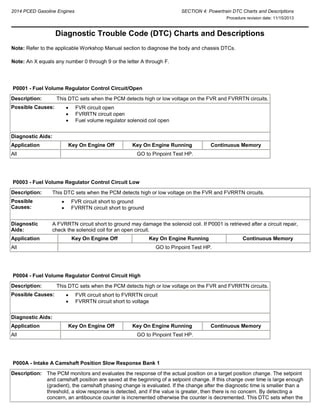
  • 1. 2014 PCED Gasoline Engines SECTION 4: Powertrain DTC Charts and Descriptions Procedure revision date: 11/15/2013 Diagnostic Trouble Code (DTC) Charts and Descriptions Note: Refer to the applicable Workshop Manual section to diagnose the body and chassis DTCs. Note: An X equals any number 0 through 9 or the letter A through F. P0001 - Fuel Volume Regulator Control Circuit/Open Description: This DTC sets when the PCM detects high or low voltage on the FVR and FVRRTN circuits. Possible Causes:  FVR circuit open  FVRRTN circuit open  Fuel volume regulator solenoid coil open Diagnostic Aids: Application Key On Engine Off Key On Engine Running Continuous Memory All GO to Pinpoint Test HP. P0003 - Fuel Volume Regulator Control Circuit Low Description: This DTC sets when the PCM detects high or low voltage on the FVR and FVRRTN circuits. Possible Causes:  FVR circuit short to ground  FVRRTN circuit short to ground Diagnostic Aids: A FVRRTN circuit short to ground may damage the solenoid coil. If P0001 is retrieved after a circuit repair, check the solenoid coil for an open circuit. Application Key On Engine Off Key On Engine Running Continuous Memory All GO to Pinpoint Test HP. P0004 - Fuel Volume Regulator Control Circuit High Description: This DTC sets when the PCM detects high or low voltage on the FVR and FVRRTN circuits. Possible Causes:  FVR circuit short to FVRRTN circuit  FVRRTN circuit short to voltage Diagnostic Aids: Application Key On Engine Off Key On Engine Running Continuous Memory All GO to Pinpoint Test HP. P000A - Intake A Camshaft Position Slow Response Bank 1 Description: The PCM monitors and evaluates the response of the actual position on a target position change. The setpoint and camshaft position are saved at the beginning of a setpoint change. If this change over time is large enough (gradient), the camshaft phasing change is evaluated. If the change after the diagnostic time is smaller than a threshold, a slow response is detected, and if the value is greater, then there is no concern. By detecting a concern, an antibounce counter is incremented otherwise the counter is decremented. This DTC sets when the
  • 2. counter exceeds an adjustable limit. Possible Causes:  Erratic camshaft position due to low oil pressure  Oil flow restriction in the oil passages or the variable camshaft timing (VCT) valve body  Camshaft advance mechanism binding (VCT unit)  Damaged VCT phaser  Radio frequency interference Diagnostic Aids: This DTC may be accompanied by other DTCs. Diagnose all camshaft position (CMP) sensor DTCs first. If no CMP sensor related DTCs are present, continue to follow diagnosis for this DTC. This DTC is a functional check of the VCT unit. Diagnose any base engine concerns related to the engine oil pressure or engine timing. Refer to the Workshop Manual Section 303-00, Engine System, Oil Pressure Test, to check the engine oil pressure. Refer to the Workshop Manual Section 303-01, Engine, Timing Drive Components, to check the engine timing and VCT phasers. Application Key On Engine Off Key On Engine Running Continuous Memory All GO to Pinpoint Test HK. P000B - Exhaust B Camshaft Position Slow Response Bank 1 Description: The PCM monitors and evaluates the response of the actual position on a target position change. The setpoint and camshaft position are saved at the beginning of a setpoint change. If this change over time is large enough (gradient), the camshaft phasing change is evaluated. If the change after the diagnostic time is smaller than a threshold, a slow response is detected, and if the value is greater, then there is no concern. By detecting a concern, an antibounce counter is incremented otherwise the counter is decremented. This DTC sets when the counter exceeds an adjustable limit. Possible Causes:  Erratic camshaft position due to low oil pressure  Oil flow restriction in the oil passages or the variable camshaft timing (VCT) valve body  Camshaft advance mechanism binding (VCT unit)  Damaged VCT phaser  Radio frequency interference Diagnostic Aids: This DTC may be accompanied by other DTCs. Diagnose all camshaft position (CMP) sensor DTCs first. If no CMP sensor related DTCs are present, continue to follow diagnosis for this DTC. This DTC is a functional check of the VCT unit. Diagnose any base engine concerns related to the engine oil pressure or engine timing. Refer to the Workshop Manual Section 303-00, Engine System, Oil Pressure Test, to check the engine oil pressure. Refer to the Workshop Manual Section 303-01, Engine, Timing Drive Components, to check the engine timing and VCT phasers. Application Key On Engine Off Key On Engine Running Continuous Memory All GO to Pinpoint Test HK. P0010 - Intake Camshaft Position Actuator Circuit/Open (Bank 1) Description: This DTC sets when a low or high voltage on the VCT11 circuit is detected. The test fails if the voltage exceeds a calibrated limit for a calibrated amount of time. Possible Causes:  VCT11 circuit open  VCT11 circuit short to voltage  VCT11 circuit short to ground  VPWR circuit open  Damaged VCT11 solenoid Diagnostic Aids:
  • 3. Application Key On Engine Off Key On Engine Running Continuous Memory All GO to Pinpoint Test HK. P0011 - Intake Camshaft Position Timing - Over-Advanced (Bank 1) Description: This DTC sets when the variable camshaft timing (VCT) position is over-advanced. The test fails when the camshaft timing exceeds a maximum calibrated value or remains in an advanced position. Possible Causes:  Camshaft timing incorrectly set  Continuous oil flow to the VCT piston chamber  Erratic camshaft position due to low oil pressure  Oil flow restriction in the oil passages or the VCT valve body  VCT11 solenoid valve stuck open  VCT11 circuit open  VCT11 circuit short to voltage  VCT11 circuit short to ground  VPWR circuit open  Camshaft advance mechanism binding (VCT unit)  Damaged VCT11 phaser  Damaged camshaft position 11 (CMP11) sensor  CMP11 sensor circuits open  CMP11 sensor circuits short to voltage  CMP11 sensor circuits short to ground  Radio frequency interference Diagnostic Aids: This DTC may be accompanied by other DTCs. Diagnose all CMP sensor DTCs first. If no CMP sensor related DTCs are present, continue to follow diagnosis for this DTC. This DTC is a functional check of the VCT unit. Diagnose any base engine concerns related to the engine oil pressure or engine timing. Refer to the Workshop Manual Section 303-00, Engine System, Oil Pressure Test, to check the engine oil pressure. Refer to the Workshop Manual Section 303-01, Engine, Timing Drive Components, to check the engine timing and VCT phasers. Application Key On Engine Off Key On Engine Running Continuous Memory All GO to Pinpoint Test HK. P0012 - Intake Camshaft Position Timing - Over-Retarded (Bank 1) Description: This DTC sets when the variable camshaft timing (VCT) position is over-retarded. The test fails when the camshaft timing exceeds a maximum calibrated value or remains in a retarded position. Possible Causes:  Camshaft timing incorrectly set  Continuous oil flow to the VCT piston chamber  Erratic camshaft position due to low oil pressure  Oil flow restriction in the oil passages or the VCT valve body  VCT11 solenoid valve stuck open  VCT11 circuit open  VCT11 circuit short to voltage  VCT11 circuit short to ground  VPWR circuit open  Camshaft advance mechanism binding (VCT unit)  Damaged VCT11 phaser  Damaged camshaft position 11 (CMP11) sensor  CMP11 sensor circuits open  CMP11 sensor circuits short to voltage  CMP11 sensor circuits short to ground  Radio frequency interference
  • 4. Diagnostic Aids: This DTC may be accompanied by other DTCs. Diagnose all CMP sensor DTCs first. If no CMP sensor related DTCs are present, continue to follow diagnosis for this DTC. This DTC is a functional check of the VCT unit. Diagnose any base engine concerns related to the engine oil pressure or engine timing. Refer to the Workshop Manual Section 303-00, Engine System, Oil Pressure Test, to check the engine oil pressure. Refer to the Workshop Manual Section 303-01, Engine, Timing Drive Components, to check the engine timing and VCT phasers. Application Key On Engine Off Key On Engine Running Continuous Memory All GO to Pinpoint Test HK. P0013 - Exhaust Camshaft Position Actuator Circuit/Open (Bank 1) Description: This DTC sets when a low or high voltage on the VCT12 circuit is detected. The test fails if the voltage exceeds a calibrated limit for a calibrated amount of time. Possible Causes:  VCT12 circuit open  VCT12 circuit short to voltage  VCT12 circuit short to ground  VPWR circuit open  Damaged VCT12 solenoid Diagnostic Aids: Application Key On Engine Off Key On Engine Running Continuous Memory All GO to Pinpoint Test HK. P0014 - Exhaust Camshaft Position Timing - Over-Advanced (Bank 1) Description: This DTC sets when the variable camshaft timing (VCT) position is over-advanced. The test fails when the camshaft timing exceeds a maximum calibrated value or remains in an advanced position. Possible Causes:  Camshaft timing incorrectly set  Continuous oil flow to the VCT piston chamber  Erratic camshaft position due to low oil pressure  Oil flow restriction in the oil passages or the VCT valve body  VCT12 solenoid valve stuck open  VCT12 circuit open  VCT12 circuit short to voltage  VCT12 circuit short to ground  VPWR circuit open  Camshaft advance mechanism binding (VCT unit)  Damaged VCT12 phaser  Damaged camshaft position (CMP12) sensor  CMP12 sensor circuits open  CMP12 sensor circuits short to voltage  CMP12 sensor circuits short to ground  Radio frequency interference Diagnostic Aids: This DTC may be accompanied by other DTCs. Diagnose all CMP sensor DTCs first. If no CMP sensor related DTCs are present, continue to follow diagnosis for this DTC. This DTC is a functional check of the VCT unit. Diagnose any base engine concerns related to the engine oil pressure or engine timing. Refer to the Workshop Manual Section 303-00, Engine System, Oil Pressure Test, to check the engine oil pressure. Refer to the Workshop Manual Section 303-01, Engine, Timing Drive Components, to check the engine timing and VCT phasers. Application Key On Engine Off Key On Engine Running Continuous Memory
  • 5. All GO to Pinpoint Test HK. P0015 - Exhaust Camshaft Position Timing - Over-Retarded (Bank 1) Description: This DTC sets when the variable camshaft timing (VCT) position is over-retarded. The test fails when the camshaft timing exceeds a maximum calibrated value or remains in a retarded position. Possible Causes:  Camshaft timing incorrectly set  Continuous oil flow to the VCT piston chamber  Erratic camshaft position due to low oil pressure  Oil flow restriction in the oil passages or the VCT valve body  VCT12 solenoid valve stuck open  VCT12 circuit open  VCT12 circuit short to voltage  VCT12 circuit short to ground  VPWR circuit open  Camshaft advance mechanism binding (VCT unit)  Damaged VCT12 phaser  Damaged camshaft position (CMP12) sensor  CMP12 sensor circuits open  CMP12 sensor circuits short to voltage  CMP12 sensor circuits short to ground  Radio frequency interference Diagnostic Aids: This DTC may be accompanied by other DTCs. Diagnose all CMP sensor DTCs first. If no CMP sensor related DTCs are present, continue to follow diagnosis for this DTC. This DTC is a functional check of the VCT unit. Diagnose any base engine concerns related to the engine oil pressure or engine timing. Refer to the Workshop Manual Section 303-00, Engine System, Oil Pressure Test, to check the engine oil pressure. Refer to the Workshop Manual Section 303-01, Engine, Timing Drive Components, to check the engine timing and VCT phasers. Application Key On Engine Off Key On Engine Running Continuous Memory All GO to Pinpoint Test HK. P0016 - Crankshaft Position - Camshaft Position Correlation - Bank 1 Sensor A Description: This DTC sets when a misalignment between the camshaft and crankshaft is detected. The test fails when the misalignment is 1 tooth or greater. This DTC can also set due to VCT system concerns (oil contamination or VCT solenoid stuck). Possible Causes:  Camshaft timing incorrectly set  Continuous oil flow to the VCT piston chamber  Erratic camshaft position due to low oil pressure  Oil flow restriction in the oil passages or the VCT valve body  VCT11 solenoid stuck in position  VCT11 circuit open  VCT11 circuit short to voltage  VCT11 circuit short to ground  VPWR circuit open  Camshaft advance mechanism binding (VCT unit)  Damaged VCT11 phaser  Damaged camshaft position 11 (CMP11) sensor  CMP11 sensor circuits open  CMP11 sensor circuits short to voltage  CMP11 sensor circuits short to ground  Radio frequency interference
  • 6. Diagnostic Aids: This DTC may be accompanied by other DTCs. Diagnose all CMP sensor DTCs first. If no CMP sensor related DTCs are present, continue to follow diagnosis for this DTC. This DTC is a functional check of the VCT unit. Diagnose any base engine concerns related to the engine oil pressure or engine timing. Refer to the Workshop Manual Section 303-00, Engine System, Oil Pressure Test, to check the engine oil pressure. Refer to the Workshop Manual Section 303-01, Engine, Timing Drive Components, to check the engine timing and VCT phasers. Application Key On Engine Off Key On Engine Running Continuous Memory All GO to Pinpoint Test HK. P0017 - Crankshaft Position - Camshaft Position Correlation - Bank 1 Sensor B Description: This DTC sets when a misalignment between the camshaft and crankshaft is detected. The test fails when the misalignment is 1 tooth or greater. This DTC can also set due to VCT system concerns (oil contamination or VCT solenoid stuck). Possible Causes:  Camshaft timing incorrectly set  Continuous oil flow to the VCT piston chamber  Erratic camshaft position due to low oil pressure  Oil flow restriction in the oil passages or the VCT valve body  VCT12 solenoid stuck in position  VCT12 circuit open  VCT12 circuit short to voltage  VCT12 circuit short to ground  VPWR circuit open  Camshaft advance mechanism binding (VCT unit)  Damaged VCT12 phaser  Damaged camshaft position 12 (CMP12) sensor  CMP12 sensor circuits open  CMP12 sensor circuits short to voltage  CMP12 sensor circuits short to ground  Radio frequency interference Diagnostic Aids: This DTC may be accompanied by other DTCs. Diagnose all CMP sensor DTCs first. If no CMP sensor related DTCs are present, continue to follow diagnosis for this DTC. This DTC is a functional check of the VCT unit. Diagnose any base engine concerns related to the engine oil pressure or engine timing. Refer to the Workshop Manual Section 303-00, Engine System, Oil Pressure Test, to check the engine oil pressure. Refer to the Workshop Manual Section 303-01, Engine, Timing Drive Components, to check the engine timing and VCT phasers. Application Key On Engine Off Key On Engine Running Continuous Memory All GO to Pinpoint Test HK. P0018 - Crankshaft Position - Camshaft Position Correlation - Bank 2 Sensor A Description: This DTC sets when a misalignment between the camshaft and crankshaft is detected. The test fails when the misalignment is 1 tooth or greater. This DTC can also set due to VCT system concerns (oil contamination or VCT solenoid stuck). Possible Causes:  Camshaft timing incorrectly set  Continuous oil flow to the VCT piston chamber  Erratic camshaft position due to low oil pressure  Oil flow restriction in the oil passages or the VCT valve body  VCT21 solenoid stuck in position  VCT21 circuit open  VCT21 circuit short to voltage  VCT21 circuit short to ground  VPWR circuit open
  • 7.  Camshaft advance mechanism binding (VCT unit)  Damaged VCT21 phaser  Damaged camshaft position 21 (CMP21) sensor  CMP21 sensor circuits open  CMP21 sensor circuits short to voltage  CMP21 sensor circuits short to ground  Radio frequency interference Diagnostic Aids: This DTC may be accompanied by other DTCs. Diagnose all CMP sensor DTCs first. If no CMP sensor related DTCs are present, continue to follow diagnosis for this DTC. This DTC is a functional check of the VCT unit. Diagnose any base engine concerns related to the engine oil pressure or engine timing. Refer to the Workshop Manual Section 303-00, Engine System, Oil Pressure Test, to check the engine oil pressure. Refer to the Workshop Manual Section 303-01, Engine, Timing Drive Components, to check the engine timing and VCT phasers. Application Key On Engine Off Key On Engine Running Continuous Memory All GO to Pinpoint Test HK. P0019 - Crankshaft Position - Camshaft Position Correlation - Bank 2 Sensor B Description: This DTC sets when a misalignment between the camshaft and crankshaft is detected. The test fails when the misalignment is 1 tooth or greater. This DTC can also set due to VCT system concerns (oil contamination or VCT solenoid stuck). Possible Causes:  Camshaft timing incorrectly set  Continuous oil flow to the VCT piston chamber  Erratic camshaft position due to low oil pressure  Oil flow restriction in the oil passages or the VCT valve body  VCT22 solenoid stuck in position  VCT22 circuit open  VCT22 circuit short to voltage  VCT22 circuit short to ground  VPWR circuit open  Camshaft advance mechanism binding (VCT unit)  Damaged VCT22 phaser  Damaged camshaft position 22 (CMP22) sensor  CMP22 sensor circuits open  CMP22 sensor circuits short to voltage  CMP22 sensor circuits short to ground  Radio frequency interference Diagnostic Aids: This DTC may be accompanied by other DTCs. Diagnose all CMP sensor DTCs first. If no CMP sensor related DTCs are present, continue to follow diagnosis for this DTC. This DTC is a functional check of the VCT unit. Diagnose any base engine concerns related to the engine oil pressure or engine timing. Refer to the Workshop Manual Section 303-00, Engine System, Oil Pressure Test, to check the engine oil pressure. Refer to the Workshop Manual Section 303-01, Engine, Timing Drive Components, to check the engine timing and VCT phasers. Application Key On Engine Off Key On Engine Running Continuous Memory All GO to Pinpoint Test HK. P0020 - Intake Camshaft Position Actuator Circuit/Open (Bank 2) Description: This DTC sets when a low or high voltage on the VCT21 circuit is detected. The test fails if the voltage exceeds a calibrated limit for a calibrated amount of time. Possible  VCT21 circuit open
  • 8. Causes:  VCT21 circuit short to voltage  VCT21 circuit short to ground  VPWR circuit open  Damaged VCT21 solenoid Diagnostic Aids: Application Key On Engine Off Key On Engine Running Continuous Memory All GO to Pinpoint Test HK. P0021 - Intake Camshaft Position Timing - Over-Advanced (Bank 2) Description: This DTC sets when the variable camshaft timing (VCT) position is over-advanced. The test fails when the camshaft timing exceeds a maximum calibrated value or remains in an advanced position. Possible Causes:  Camshaft timing incorrectly set  Continuous oil flow to the VCT piston chamber  Erratic camshaft position due to low oil pressure  Oil flow restriction in the oil passages or the VCT valve body  VCT21 solenoid valve stuck open  VCT21 circuit open  VCT21 circuit short to voltage  VCT21 circuit short to ground  VPWR circuit open  Camshaft advance mechanism binding (VCT unit)  Damaged VCT21 phaser  Damaged camshaft position 21 (CMP21) sensor  CMP21 sensor circuits open  CMP21 sensor circuits short to voltage  CMP21 sensor circuits short to ground  Radio frequency interference Diagnostic Aids: This DTC may be accompanied by other DTCs. Diagnose all CMP sensor DTCs first. If no CMP sensor related DTCs are present, continue to follow diagnosis for this DTC. This DTC is a functional check of the VCT unit. Diagnose any base engine concerns related to the engine oil pressure or engine timing. Refer to the Workshop Manual Section 303-00, Engine System, Oil Pressure Test, to check the engine oil pressure. Refer to the Workshop Manual Section 303-01, Engine, Timing Drive Components, to check the engine timing and VCT phasers. Application Key On Engine Off Key On Engine Running Continuous Memory All GO to Pinpoint Test HK. P0022 - Intake Camshaft Position Timing - Over-Retarded (Bank 2) Description: This DTC sets when the variable camshaft timing (VCT) position is over-retarded. The test fails when the camshaft timing exceeds a maximum calibrated value or remains in a retarded position. Possible Causes:  Camshaft timing incorrectly set  Continuous oil flow to the VCT piston chamber  Erratic camshaft position due to low oil pressure  Oil flow restriction in the oil passages or the VCT valve body  VCT21 solenoid valve stuck open  VCT21 circuit open  VCT21 circuit short to voltage  VCT21 circuit short to ground  VPWR circuit open  Camshaft advance mechanism binding (VCT unit)
  • 9.  Damaged VCT21 phaser  Damaged camshaft position 21 (CMP21) sensor  CMP21 sensor circuits open  CMP21 sensor circuits short to voltage  CMP21 sensor circuits short to ground  Radio frequency interference Diagnostic Aids: This DTC may be accompanied by other DTCs. Diagnose all CMP sensor DTCs first. If no CMP sensor related DTCs are present, continue to follow diagnosis for this DTC. This DTC is a functional check of the VCT unit. Diagnose any base engine concerns related to the engine oil pressure or engine timing. Refer to the Workshop Manual Section 303-00, Engine System, Oil Pressure Test, to check the engine oil pressure. Refer to the Workshop Manual Section 303-01, Engine, Timing Drive Components, to check the engine timing and VCT phasers. Application Key On Engine Off Key On Engine Running Continuous Memory All GO to Pinpoint Test HK. P0023 - Exhaust Camshaft Position Actuator Circuit/Open (Bank 2) Description: This DTC sets when a low or high voltage on the VCT22 circuit is detected. The test fails if the voltage exceeds a calibrated limit for a calibrated amount of time. Possible Causes:  VCT22 circuit open  VCT22 circuit short to voltage  VCT22 circuit short to ground  VPWR circuit open  Damaged VCT22 solenoid Diagnostic Aids: Application Key On Engine Off Key On Engine Running Continuous Memory All GO to Pinpoint Test HK. P0024 - Exhaust Camshaft Position Timing - Over-Advanced (Bank 2) Description: This DTC sets when the variable camshaft timing (VCT) position is over-advanced. The test fails when the camshaft timing exceeds a maximum calibrated value or remains in an advanced position. Possible Causes:  Camshaft timing incorrectly set  Continuous oil flow to the VCT piston chamber  Erratic camshaft position due to low oil pressure  Oil flow restriction in the oil passages or the VCT valve body  VCT22 solenoid valve stuck open  VCT22 circuit open  VCT22 circuit short to voltage  VCT22 circuit short to ground  VPWR circuit open  Camshaft advance mechanism binding (VCT unit)  Damaged VCT22 phaser  Damaged camshaft position 22 (CMP22) sensor  CMP22 sensor circuits open  CMP22 sensor circuits short to voltage  CMP22 sensor circuits short to ground  Radio frequency interference Diagnostic This DTC may be accompanied by other DTCs. Diagnose all CMP sensor DTCs first. If no CMP sensor related
  • 10. Aids: DTCs are present, continue to follow diagnosis for this DTC. This DTC is a functional check of the VCT unit. Diagnose any base engine concerns related to the engine oil pressure or engine timing. Refer to the Workshop Manual Section 303-00, Engine System, Oil Pressure Test, to check the engine oil pressure. Refer to the Workshop Manual Section 303-01, Engine, Timing Drive Components, to check the engine timing and VCT phasers. Application Key On Engine Off Key On Engine Running Continuous Memory All GO to Pinpoint Test HK. P0025 - Exhaust Camshaft Position Timing - Over-Retarded (Bank 2) Description: This DTC sets when the variable camshaft timing (VCT) position is over-retarded. The test fails when the camshaft timing exceeds a maximum calibrated value or remains in a retarded position. Possible Causes:  Camshaft timing incorrectly set  Continuous oil flow to the VCT piston chamber  Erratic camshaft position due to low oil pressure  Oil flow restriction in the oil passages or the VCT valve body  VCT22 solenoid valve stuck open  VCT22 circuit open  VCT22 circuit short to voltage  VCT22 circuit short to ground  VPWR circuit open  Camshaft advance mechanism binding (VCT unit)  Damaged VCT22 phaser  Damaged camshaft position 22 (CMP22) sensor  CMP22 sensor circuits open  CMP22 sensor circuits short to voltage  CMP22 sensor circuits short to ground  Radio frequency interference Diagnostic Aids: This DTC may be accompanied by other DTCs. Diagnose all CMP sensor DTCs first. If no CMP sensor related DTCs are present, continue to follow diagnosis for this DTC. This DTC is a functional check of the VCT unit. Diagnose any base engine concerns related to the engine oil pressure or engine timing. Refer to the Workshop Manual Section 303-00, Engine System, Oil Pressure Test, to check the engine oil pressure. Refer to the Workshop Manual Section 303-01, Engine, Timing Drive Components, to check the engine timing and VCT phasers. Application Key On Engine Off Key On Engine Running Continuous Memory All GO to Pinpoint Test HK. P0030 - HO2S Heater Control Circuit (Bank 1, Sensor 1) Description: The PCM controls the universal heated oxygen sensor bank 1, sensor 1 (HO2S11) heater ON and OFF duty cycle to maintain a calibrated temperature. This DTC sets when the sensor does not warm up to the required temperature in a calibrated amount of time. This DTC also sets when the PCM is not able to maintain the required temperature after the sensor is warm. Possible Causes:  UO2S11 circuit open  UO2SGREF11 circuit open  UO2SHTR11 circuit open  UO2SHTR11 circuit short to voltage  VPWR circuit open  Incorrect connections  Damaged or corroded terminals  Exhaust temperature significantly higher than expected
  • 11.  Damaged universal HO2S11 Diagnostic Aids: Inspect the connectors for signs of damage, water intrusion or corrosion. Application Key On Engine Off Key On Engine Running Continuous Memory All GO to Pinpoint Test DZ. P0034 - Turbocharger/Supercharger Bypass Valve A Control Circuit Low Description: This DTC sets when the PCM detects a short to ground in the TCBY circuit. Possible Causes:  Damaged turbocharger bypass (TCBY) valve  TCBY circuit short to ground  Damaged harness connector  Damaged harness Diagnostic Aids: Check the harness for intermittent concerns, incorrect connections, routing, alterations and damage due to contact with other components. This DTC only sets when the valve is commanded closed. Application Key On Engine Off Key On Engine Running Continuous Memory All GO to Pinpoint Test HN. P0035 - Turbocharger/Supercharger Bypass Valve A Control Circuit High Description: This DTC sets when the PCM detects an open circuit or high voltage in the TCBY circuit. Possible Causes:  Damaged turbocharger bypass (TCBY) valve  TCBY circuit open  TCBY circuit short to voltage Diagnostic Aids: Check the harness for intermittent concerns, incorrect connections, routing, alterations and damage due to contact with other components. This DTC only sets when the valve is commanded open. Application Key On Engine Off Key On Engine Running Continuous Memory All GO to Pinpoint Test HN. P0036 - HO2S Heater Control Circuit (Bank 1, Sensor 2) Description: The PCM controls the heated oxygen sensor bank 1, sensor 2 (HO2S12) heater ON and OFF duty cycle to maintain a calibrated temperature. This DTC sets when the sensor does not warm up to the required temperature in a calibrated amount of time. This DTC also sets when the PCM is not able to maintain the required temperature after the sensor is warm. Possible Causes:  VPWR circuit open  HTR12 circuit open  HTR12 circuit short  Incorrect connections  Damaged or corroded terminals  Exhaust temperature significantly higher than expected  Damaged HO2S12
  • 12. Diagnostic Aids: Inspect the connectors for signs of damage, water intrusion or corrosion. Application Key On Engine Off Key On Engine Running Continuous Memory All GO to Pinpoint Test DW. P0037 - HO2S Heater Control Circuit Low (Bank 1, Sensor 2) Description: The PCM controls the heated oxygen sensor bank 1, sensor 2 (HO2S12) heater ON and OFF duty cycle to maintain a calibrated temperature. This DTC sets when the sensor does not warm up to the required temperature in a calibrated amount of time. This DTC also sets when the PCM is not able to maintain the required temperature after the sensor is warm. Possible Causes:  HTR12 circuit short  Incorrect connections  Damaged or corroded terminals  Exhaust temperature significantly higher than expected  Damaged HO2S12 Diagnostic Aids: Inspect the connectors for signs of damage, water intrusion or corrosion. Application Key On Engine Off Key On Engine Running Continuous Memory All GO to Pinpoint Test DW. P0038 - HO2S Heater Control Circuit High (Bank 1, Sensor 2) Description: The PCM controls the heated oxygen sensor bank 1, sensor 2 (HO2S12) heater ON and OFF duty cycle to maintain a calibrated temperature. This DTC sets when the sensor does not warm up to the required temperature in a calibrated amount of time. This DTC also sets when the PCM is not able to maintain the required temperature after the sensor is warm. Possible Causes:  HTR12 circuit short  Incorrect connections  Damaged or corroded terminals  Exhaust temperature significantly higher than expected  Damaged HO2S12 Diagnostic Aids: Inspect the connectors for signs of damage, water intrusion or corrosion. Application Key On Engine Off Key On Engine Running Continuous Memory All GO to Pinpoint Test DW. P0040 - Oxygen Sensor Signals Swapped Bank 1 Sensor 1/Bank 2 Sensor 1 Description: The heated oxygen sensor (HO2S) monitor determines if the universal HO2S signal response for a fuel shift corresponds to the correct engine bank. This DTC sets when there is no response from the universal HO2S being tested. Possible Causes:  Crossed universal HO2S harness connectors  Crossed universal HO2S wiring at the harness connectors  Crossed universal HO2S wiring at the PCM connectors Diagnostic Aids: Connect the universal HO2S connector to the correct bank. Application Key On Engine Off Key On Engine Running Continuous Memory
  • 13. All GO to Pinpoint Test DZ. P0041 - Oxygen Sensor Signals Swapped Bank 1 Sensor 2/Bank 2 Sensor 2 Description: The heated oxygen sensor (HO2S) monitor determines if the HO2S signal response for a fuel shift corresponds to the correct engine bank. This DTC sets when there is no response from the HO2S being tested. Possible Causes:  Crossed HO2S harness connectors  Crossed HO2S wiring at the harness connectors  Crossed HO2S wiring at the PCM connectors Diagnostic Aids: Connect the HO2S connector to the correct bank. Application Key On Engine Off Key On Engine Running Continuous Memory All GO to Pinpoint Test DW. P0050 - HO2S Heater Control Circuit (Bank 2, Sensor 1) Description: The PCM controls the universal heated oxygen sensor bank 2, sensor 1 (HO2S21) heater ON and OFF duty cycle to maintain a calibrated temperature. This DTC sets when the sensor does not warm up to the required temperature in a calibrated amount of time. This DTC also sets when the PCM is not able to maintain the required temperature after the sensor is warm. Possible Causes:  UO2S21 circuit open  UO2SGREF21 circuit open  UO2SHTR21 circuit open  UO2SHTR21 circuit short to voltage  VPWR circuit open  Incorrect connections  Damaged or corroded terminals  Exhaust temperature significantly higher than expected  Damaged universal HO2S21 Diagnostic Aids: Inspect the connectors for signs of damage, water intrusion or corrosion. Application Key On Engine Off Key On Engine Running Continuous Memory All GO to Pinpoint Test DZ. P0053 - HO2S Heater Resistance (Bank 1, Sensor 1) Description: This DTC sets when the heater current requirements are too low or too high in the UO2SHTR11 circuit. Possible Causes:  VPWR circuit open  UO2SHTR11 circuit open  UO2SHTR11 circuit short  Damaged universal HO2S11 heater Diagnostic Aids: Inspect the connectors for signs of damage, water intrusion or corrosion. Application Key On Engine Off Key On Engine Running Continuous Memory All GO to Pinpoint Test DZ. P0054 - HO2S Heater Resistance (Bank 1, Sensor 2)
  • 14. Description: This DTC sets when the heater current requirements are too low or too high in the HTR12 circuit. Possible Causes:  VPWR circuit open  HTR12 circuit open  HTR12 heater circuit short  Damaged HO2S12 heater Diagnostic Aids: Inspect the connectors for signs of damage, water intrusion or corrosion. Application Key On Engine Off Key On Engine Running Continuous Memory All GO to Pinpoint Test DW. P0056 - HO2S Heater Control Circuit (Bank 1, Sensor 2) Description: The PCM controls the heated oxygen sensor bank 1, sensor 2 (HO2S12) heater ON and OFF duty cycle to maintain a calibrated temperature. This DTC sets when the sensor does not warm up to the required temperature in a calibrated amount of time. This DTC also sets when the PCM is not able to maintain the required temperature after the sensor is warm. Possible Causes:  VPWR circuit open  HTR12 circuit open  HTR12 circuit short  Incorrect connections  Damaged or corroded terminals  Exhaust temperature significantly higher than expected  Damaged HO2S12 Diagnostic Aids: Inspect the connectors for signs of damage, water intrusion or corrosion. Application Key On Engine Off Key On Engine Running Continuous Memory All GO to Pinpoint Test DW. P0059 - HO2S Heater Resistance (Bank 2, Sensor 1) Description: This DTC sets when the heater current requirements are too low or too high in the UO2SHTR21 circuit. Possible Causes:  VPWR circuit open  UO2SHTR21 circuit open  UO2SHTR21 circuit short  Damaged universal HO2S21 heater Diagnostic Aids: Inspect the connectors for signs of damage, water intrusion or corrosion. Application Key On Engine Off Key On Engine Running Continuous Memory All GO to Pinpoint Test DZ. P0060 - HO2S Heater Resistance (Bank 2, Sensor 2) Description: This DTC sets when the heater current requirements are too low or too high in the HTR22 circuit. Possible Causes:  VPWR circuit open  HTR22 circuit open  HTR22 circuit short  Damaged HO2S22 heater Diagnostic Aids: Inspect the connectors for signs of damage, water intrusion or corrosion.
  • 15. Application Key On Engine Off Key On Engine Running Continuous Memory All GO to Pinpoint Test DW. P0068 - Manifold Absolute Pressure (MAP)/Mass Air Flow (MAF) - Throttle Position Correlation Description: The PCM monitors a vehicle operation rationality check by comparing sensed throttle position to mass airflow readings. This continuous memory DTC sets when during a key ON, engine running (KOER) self-test, the comparison of the throttle position (TP) sensor and MAF sensor readings are not consistent with the calibrated load values. Possible Causes:  Air leak at any connection or line of the intake air system components before or after the electronic throttle body (ETB)  Leak in the positive crankcase ventilation (PCV) system  TP sensor not seated correctly  Damaged MAF sensor  Damaged TP sensor Diagnostic Aids: An intake air system leak at a hose, line or connection of any intake air system or PCV system component may cause this DTC to set. Diagnose any MAF or TP DTCs first. If the throttle plate is closed and the LOAD PID is greater than 55%, or with the throttle plate at wide open throttle (WOT) with the LOAD PID less than 30% indicates a concern is present. Application Key On Engine Off Key On Engine Running Continuous Memory All GO to Pinpoint Test DV. P0071 - Ambient Air Temperature Sensor Circuit Range/Performance Description: This DTC sets when the ambient air temperature (AAT) sensor reading does not correlate with the other temperature sensor readings at ignition ON. The PCM runs this logic after an engine off and a calibrated soak period, typically 6 to 8 hours. This soak period allows the AAT sensor and the other temperature sensors to stabilize and not differ by greater than a calibrated value, typically 18°C (32.4°F). Possible Causes:  Damaged AAT sensor Diagnostic Aids: Make sure the AAT sensor reading and the other temperature sensor readings are similar when the engine is cold and the vehicle has not been in direct sun light. Application Key On Engine Off Key On Engine Running Continuous Memory All GO to Pinpoint Test FA. P0072 - Ambient Air Temperature Sensor Circuit Low Description: This DTC sets when the ambient air temperature (AAT) sensor signal is less than the self-test minimum. Possible Causes:  AAT circuit short to ground  Damaged AAT sensor Diagnostic Aids: Application Key On Engine Off Key On Engine Running Continuous Memory All GO to Pinpoint Test FA.
  • 16. P0073 - Ambient Air Temperature Sensor Circuit High Description: This DTC sets when the ambient air temperature (AAT) sensor signal is greater than the self-test maximum. Possible Causes:  AAT circuit open  AAT circuit short to voltage  Damaged AAT sensor Diagnostic Aids: Application Key On Engine Off Key On Engine Running Continuous Memory All GO to Pinpoint Test FA. P0074 - Ambient Air Temperature Sensor Circuit Intermittent/Erratic Description: This DTC sets when the ambient air temperature (AAT) sensor signal changes beyond the minimum or maximum calibrated limit. Possible Causes:  AAT circuit intermittent open  AAT circuit intermittent short to voltage  AAT circuit intermittent short to ground  Damaged AAT sensor Diagnostic Aids: Check the harness and connection. Monitor the sensor PID while wiggling and bending the harness from the sensor to the PCM. Application Key On Engine Off Key On Engine Running Continuous Memory All GO to Pinpoint Test FA. P007B - Charge Air Cooler Temperature Sensor Circuit Range/Performance (Bank 1) Description: This DTC sets when the CAC_T PID does not correlate with the IAT or the IAT2 PIDs at ignition ON or if the IAT PID reading is greater than a maximum calibrated value while driving. Possible Causes:  Damaged turbocharger boost pressure (TCBP)/charge air cooler temperature (CACT) sensor  Contaminated or blocked TCBP/CACT sensor  Slow responding TCBP/CACT sensor Diagnostic Aids: Check temperature values while engine is at ambient temperature, cold soak the engine for a minimum of 6 hours if necessary. Check airflow through charge air cooler (CAC), remove debris if necessary. The TCBP/CACT sensor is a dual function pressure and temperature sensor located on the intake air tube between the turbocharger and the throttle body. Application Key On Engine Off Key On Engine Running Continuous Memory All GO to Pinpoint Test EA. P007C - Charge Air Cooler Temperature Sensor Circuit Low (Bank 1) Description: This DTC sets when the charge air cooler temperature (CACT) is greater than a calibrated value or a short to ground is detected in the CACT circuit. Possible Causes:  Damaged turbocharger boost pressure (TCBP)/charge air cooler temperature (CACT) sensor  CACT circuit short to ground  VPWR circuit open  Low airflow through the charge air cooler (CAC)
  • 17.  Damaged harness connector  Damaged harness Diagnostic Aids: Check the harness for intermittent concerns, incorrect connections, routing, alterations and damage due to contact with other components. The TCBP/CACT sensor is a dual function pressure and temperature sensor located on the intake air tube between the turbocharger and the throttle body. Application Key On Engine Off Key On Engine Running Continuous Memory All GO to Pinpoint Test DN. P007D - Charge Air Cooler Temperature Sensor Circuit High (Bank 1) Description: This DTC sets when the charge air cooler temperature (CACT) is lower than a calibrated value or an open or short to voltage is detected in the CACT circuit. Possible Causes:  Damaged turbocharger boost pressure (TCBP) sensor/charge air cooler temperature (CACT) sensor  CACT circuit open  CACT circuit short to voltage  SIGRTN circuit open  Output from the charge air cooler (CAC) is colder than the calibrated threshold Diagnostic Aids: Check the harness for intermittent concerns, incorrect connections, routing, alterations and damage due to contact with other components. The TCBP/CACT sensor is a dual function pressure and temperature sensor located on the intake air tube between the charge air cooler (CAC) and the throttle body. Application Key On Engine Off Key On Engine Running Continuous Memory All GO to Pinpoint Test DN. P0087 - Fuel Rail/System Pressure - Too Low Description: The PCM regulates the fuel rail pressure by controlling the fuel volume regulator. This DTC sets when the PCM is no longer capable of maintaining the fuel pressure within the calibrated parameters. Possible Causes:  Fuel filter plugged or dirty  Fuel supply line restricted  Damaged fuel pump module  Damaged fuel injection pump Diagnostic Aids: Diagnose any FRP and FVR circuit DTCs first. Application Key On Engine Off Key On Engine Running Continuous Memory All GO to Pinpoint Test HP. P0088 - Fuel Rail/System Pressure - Too High Description: The PCM regulates the fuel rail pressure by controlling the fuel volume regulator. This DTC sets when the PCM is no longer capable of maintaining the fuel pressure within the calibrated parameters. Possible Causes:  Damaged fuel injection pump Diagnostic Aids:
  • 18. Application Key On Engine Off Key On Engine Running Continuous Memory All GO to Pinpoint Test HP. P008A - Low Pressure Fuel System Pressure - Too Low Description: The PCM monitors the fuel pressure sensor. This DTC sets when the low pressure fuel system pressure falls below an expected threshold. Possible Causes:  Low or no fuel  Low fuel pressure  Damaged fuel pressure sensor Diagnostic Aids: Application Key On Engine Off Key On Engine Running Continuous Memory All GO to Pinpoint Test HC. P008B - Low Pressure Fuel System Pressure - Too High Description: The PCM monitors the fuel pressure sensor. This DTC sets when the low pressure fuel system pressure rises above an expected threshold. Possible Causes:  High fuel pressure  Damaged fuel pressure sensor Diagnostic Aids: Application Key On Engine Off Key On Engine Running Continuous Memory All GO to Pinpoint Test HC. P0093 - Fuel System Leak Detected - Large Leak Description: This DTC sets when the PCM detects an air leak that exceeds a calibrated limit for greater than 5 seconds. If the airflow entering the engine exceeds the airflow through the throttle, a leak is detected and this diagnostic fails. Possible Causes:  Unmetered air leaks between throttle body and intake valves  Air leaks at the intake manifold  Positive crankcase ventilation (PCV) system is leaking Diagnostic Aids: Verify the integrity of the PCV system. Refer to Section 1, Positive Crankcase Ventilation (PCV) System for system information. Application Key On Engine Off Key On Engine Running Continuous Memory All GO to Pinpoint Test HG. P0094 - Fuel System Leak Detected - Small Leak Description: This DTC sets when the PCM detects an air leak that exceeds a calibrated limit for greater than 5 seconds. If the airflow entering the engine exceeds the airflow through the throttle, a leak is detected and this diagnostic fails. Possible  Unmetered air leaks between throttle body and intake valves
  • 19. Causes:  Air leaks at the intake manifold  Positive crankcase ventilation (PCV) system is leaking Diagnostic Aids: Verify the integrity of the PCV system. Refer to Section 1, Positive Crankcase Ventilation (PCV) System for system information. Application Key On Engine Off Key On Engine Running Continuous Memory All GO to Pinpoint Test HG. P0096 - Intake Air Temperature Sensor 2 Circuit Range/Performance (Bank 1) Description: This DTC sets when the intake air temperature 2 (IAT2) sensor PID does not correlate with the charge air cooler temperature (CAC_T) sensor or the intake air temperature (IAT) sensor PIDs at ignition ON. It also sets if the IAT2 sensor PID exceeds the maximum calibrated temperature threshold while driving. Possible Causes:  Slow responding manifold absolute pressure (MAP)/intake air temperature 2 (IAT2) sensor  Damaged MAP/IAT2 sensor Diagnostic Aids: The MAP/IAT2 sensor is located on top of the intake manifold. Aftermarket heaters that are attached to the engine, transmission or battery may cause DTC P0096 to set in cold weather climates after a 6 hour soak period. Application Key On Engine Off Key On Engine Running Continuous Memory All GO to Pinpoint Test EA. P0097 - Intake Air Temperature Sensor 2 Circuit Low Description: This DTC sets when the intake air temperature 2 (IAT2) sensor signal is less than the self-test minimum. The IAT2 sensor minimum is 0.2 volt. Possible Causes:  IAT2 circuit short to ground  Incorrect harness connection  Damaged IAT2 sensor Diagnostic Aids: Monitor the IAT2 sensor PID value. A typical IAT2 sensor temperature should be greater than the IAT sensor temperature. Application Key On Engine Off Key On Engine Running Continuous Memory Explorer 3.5L GTDI, F-150 3.5L, Flex 3.5L GTDI, MKS 3.5L, MKT 3.5L, Taurus 3.5L GTDI GO to Pinpoint Test DN. All others GO to Pinpoint Test DU. P0098 - Intake Air Temperature Sensor 2 Circuit High Description: This DTC sets when the intake air temperature 2 (IAT2) sensor signal is greater than the self-test maximum. The IAT2 sensor maximum is 4.6 volts.
  • 20. Possible Causes:  IAT2 circuit open  IAT2 circuit short to voltage  Incorrect harness connection  Damaged IAT2 sensor Diagnostic Aids: Monitor the IAT2 sensor PID value. A typical IAT2 sensor temperature should be greater than the IAT sensor temperature. Application Key On Engine Off Key On Engine Running Continuous Memory Explorer 3.5L GTDI, F-150 3.5L, Flex 3.5L GTDI, MKS 3.5L, MKT 3.5L, Taurus 3.5L GTDI GO to Pinpoint Test DN. All others GO to Pinpoint Test DU. P00BA - Low Fuel Pressure Forced Limited Power Description: This DTC sets when the fuel delivery volume is less than the requested fuel delivery volume and the PCM has reduced engine power as a result. Possible Causes:  Restricted fuel filter  Restricted fuel supply line  Damaged or worn fuel pump  Fuel sloshing at low fuel level  Sudden acceleration  Vehicle driven on hilly or steep inclines Diagnostic Aids: Application Key On Engine Off Key On Engine Running Continuous Memory All GO to Pinpoint Test HC. P00BB - Fuel Injector Insufficient Flow - Forced Limited Power Description: This DTC sets when the requested fuel delivery volume is greater than the fuel injectors maximum delivery volume. Possible Causes:  High ethanol content in the fuel tank  Customer driving habits  Restricted fuel filter  Restricted fuel supply line  Damaged or worn fuel pump Diagnostic Aids: A high fuel ethanol content combined with pulling or carrying a heavy load up a steep grade could set this DTC. Application Key On Engine Off Key On Engine Running Continuous Memory All GO to Pinpoint Test HC.
  • 21. P00C1 - Turbocharger/Supercharger Bypass Valve B Control Circuit Low For F-150, 3.5L Description: This DTC sets when there is a short to ground in the TCBY circuit. Possible Causes:  Damaged turbocharger bypass (TCBY) valve  TCBY circuit short to ground  Damaged harness connector  Damaged harness Diagnostic Aids: Check the harness for intermittent concerns, incorrect connections, routing, alterations and damage due to contact with other components. This DTC only sets when the valve is commanded closed. For All Others Description: This DTC sets when there is a short to ground in the TCBY2 circuit. Possible Causes:  Damaged turbocharger bypass 2 (TCBY2) valve  TCBY2 circuit short to ground  Damaged harness connector  Damaged harness Diagnostic Aids: Check the harness for intermittent concerns, incorrect connections, routing, alterations and damage due to contact with other components. This DTC only sets when the valve is commanded closed. Application Key On Engine Off Key On Engine Running Continuous Memory All GO to Pinpoint Test HN. P00C2 - Turbocharger/Supercharger Bypass Valve B Control Circuit High For F-150, 3.5L Description: This DTC sets when there is an open circuit or high voltage in the TCBY circuit. Possible Causes:  Damaged turbocharger bypass (TCBY) valve  TCBY circuit open  TCBY circuit short to voltage Diagnostic Aids: Check the harness for intermittent concerns, incorrect connections, routing, alterations and damage due to contact with other components. This DTC only sets when the valve is commanded open. For All Others Description: This DTC sets when there is an open circuit or high voltage in the TCBY2 circuit. Possible Causes:  Damaged turbocharger bypass 2 (TCBY2) valve  TCBY2 circuit open  TCBY2 circuit short to voltage Diagnostic Aids: Check the harness for intermittent concerns, incorrect connections, routing, alterations and damage due to contact with other components. This DTC only sets when the valve is commanded open. Application Key On Engine Off Key On Engine Running Continuous Memory All GO to Pinpoint Test HN.
  • 22. P00C6 - Fuel Rail Pressure Too Low - Engine Cranking Description: The high pressure fuel system must reach a minimum pressure threshold before the engine can be started. This DTC sets if the high pressure fuel system cannot achieve this threshold within certain time and crankshaft rotation limits; the PCM attempts to start the engine at fuel pump assembly pressure. Possible Causes:  Fuel filter plugged or dirty  Fuel supply line restricted  Damaged fuel pump module  Damaged fuel injection pump Diagnostic Aids: Diagnose any fuel rail pressure (FRP) and FVR circuit DTCs first. Application Key On Engine Off Key On Engine Running Continuous Memory All GO to Pinpoint Test HP. P00CE - Intake Air Temperature Measurement System - Multiple Sensor Correlation Description: This DTC sets when the intake air temperature (IAT), charge air cooler temperature (CAC_T) and the intake air temperature 2 (IAT2) PIDs are each greater than 16.67°C (30°F) different from each other at start up or that each sensor is out of the calibrated range at engine start up after a soak period of at least 6 hours when a block heater is not used. Possible Causes:  Damaged IAT, CACT or IAT2 sensors  Contaminated or blocked IAT, CACT or IAT2 sensors  Slow responding IAT, CACT or IAT2 sensors Diagnostic Aids: Compare all sensor readings to the ambient temperature to determine which sensor is reading correctly. Application Key On Engine Off Key On Engine Running Continuous Memory F-150 3.5L GO to Pinpoint Test HN. All others GO to Pinpoint Test EA. P00D2 - HO2S Heater Control Circuit Range/Performance (Bank 1 Sensor 2) Description: This DTC sets when the internal impedance of the heated oxygen sensor bank 1, sensor 2 (HO2S12) exceeds the calibrated threshold. Possible Causes:  Incorrect connections  Damaged or corroded terminals  Damaged HO2S12 heater Diagnostic Aids: Inspect the connectors for signs of damage, water intrusion or corrosion. Application Key On Engine Off Key On Engine Running Continuous Memory All GO to Pinpoint Test DW. P00DF - Charge Air Cooler Coolant Temperature Sensor Circuit Range/Performance Description: This DTC sets when the charge air cooler (CAC) coolant temperature sensor PID does not correlate with the IAT sensor or the ECT sensor PIDs at ignition ON or if the CAC coolant temperature PID reading is greater than a
  • 23. maximum calibrated value while driving. Possible Causes:  Damaged CAC coolant temperature sensor  Slow responding CAC coolant temperature sensor Diagnostic Aids: Check temperature values while engine is at ambient temperature, cold soak the engine for a minimum of 6 hours if necessary. Application Key On Engine Off Key On Engine Running Continuous Memory All GO to Pinpoint Test KP. P00E0 - Charge Air Cooler Coolant Temperature Sensor Circuit Low Description: This DTC sets when the charge air cooler (CAC) coolant temperature is greater than a calibrated value or a short to ground is detected in the CACCTS circuit. Possible Causes:  CACCTS circuit short to ground  Damaged CAC coolant temperature sensor Diagnostic Aids: A CAC coolant temperature sensor reading less than the self-test minimum with ignition ON, engine OFF or during any engine operating mode indicates a concern is present. Application Key On Engine Off Key On Engine Running Continuous Memory All GO to Pinpoint Test KP. P00E1 - Charge Air Cooler Coolant Temperature Sensor Circuit High Description: This DTC sets when the charge air cooler (CAC) coolant temperature is less than a calibrated value or a short to voltage is detected in the CACCTS circuit. Possible Causes:  CACCTS circuit open  CACCTS circuit short to voltage  Damaged CAC coolant temperature sensor Diagnostic Aids: A CAC coolant temperature sensor reading greater than the self-test maximum with ignition ON, engine OFF or during any engine operating mode indicates a concern is present. Application Key On Engine Off Key On Engine Running Continuous Memory All GO to Pinpoint Test KP. P00E2 - Charge Air Cooler Coolant Temperature Sensor Intermittent/Erratic Description: This DTC sets when the charge air cooler (CAC) coolant temperature sensor signal changes from an in range value to beyond the minimum or maximum calibrated limit a calibrated number of times. Possible Causes:  CACCTS circuit intermittent open  CACCTS circuit intermittent short to ground  CACCTS circuit intermittent short to voltage  Damaged CAC coolant temperature sensor  Damaged CAC coolant temperature sensor wiring Diagnostic Aids: Check the harness and connection. Monitor the sensor PID while wiggling and bending the harness from the sensor to the PCM. Application Key On Engine Off Key On Engine Running Continuous Memory All GO to Pinpoint Test KP.
  • 24. P0100 - Mass Or Volume Air Flow A Circuit Description: This DTC sets when the mass airflow (MAF) sensor frequency changes below a minimum calibrated limit for greater than 0.5 seconds. Possible Causes:  Open MAF sensor element  Intake air system components incorrectly connected Diagnostic Aids: Install a new mass airflow/intake air temperature (MAF/IAT) sensor. Refer to the Workshop Manual Section 303-14, Electronic Engine Controls. Application Key On Engine Off Key On Engine Running Continuous Memory All Refer to the Description, Possible Causes and Diagnostic Aids for the DTC. P0101 - Mass Or Volume Air Flow A Circuit Range/Performance Description: This DTC sets when the actual airflow is less or greater than the modeled airflow by greater than a calibrated value for 2.4 seconds. Possible Causes:  Restricted airflow  Intake air system leak  Damaged mass airflow (MAF) sensor Diagnostic Aids: Check the MAF sensor for contamination and the intake air system for leaks. Application Key On Engine Off Key On Engine Running Continuous Memory All GO to Pinpoint Test DC. P0102 - Mass Or Volume Air Flow A Circuit Low Description: This DTC sets when during key ON, engine running (KOER), the mass airflow (MAF) sensor output changes below a minimum calibrated limit for greater than a set period of time. Possible Causes:  MAF circuit short to ground  Damaged MAF sensor Diagnostic Aids: Make sure the MAF sensor connector is locked and seated correctly. Application Key On Engine Off Key On Engine Running Continuous Memory All GO to Pinpoint Test DC. P0103 - Mass Or Volume Air Flow A Circuit High Description: This DTC sets when the mass airflow (MAF) sensor output changes above a maximum calibrated limit while the engine is running. Possible Causes:  MAF circuit open  MAF circuit short to voltage  Damaged MAF sensor Diagnostic Aids: Make sure the MAF sensor connector is locked and seated correctly.
  • 25. Application Key On Engine Off Key On Engine Running Continuous Memory All GO to Pinpoint Test DC. P0104 - Mass Or Volume Air Flow A Circuit Intermittent/Erratic Description: This DTC sets when a concern exists in the MAF circuit, or the air tube containing the mass airflow (MAF) sensor, causing an incorrect sensor output reading. Possible Causes:  MAF circuit intermittent open  MAF circuit intermittent short to voltage Diagnostic Aids: Check the MAF sensor tube for air leaks. Application Key On Engine Off Key On Engine Running Continuous Memory All GO to Pinpoint Test DC. P0106 - Manifold Absolute Pressure (MAP/BARO) Sensor Range/Performance For Vehicles With 3.5L GTDI Engine Description: This DTC sets when the MAP PID does not correlate with the BARO and the TCBP PIDs at ignition ON. It also sets if the MAP and TCBP PIDs fail to correlate when running, but the TCBP PID does correlate with the BARO PID at idle. Possible Causes:  Slow responding manifold absolute pressure (MAP)/intake air temperature 2 (IAT2) sensor  Damaged MAP/IAT2 sensor Diagnostic Aids: For All Others Description: This DTC sets when the manifold absolute pressure (MAP) sensor input does not correlate with an inferred MAP value. The inferred value is based on the mass airflow (MAF) sensor. Possible Causes:  Slow responding MAP sensor  Damaged MAP sensor  Damaged MAF sensor Diagnostic Aids: Application Key On Engine Off Key On Engine Running Continuous Memory Explorer 3.5L GTDI, F-150 3.5L, Flex 3.5L GTDI, MKS 3.5L, MKT 3.5L, Taurus 3.5L GTDI GO to Pinpoint Test EA. All others GO to Pinpoint Test DM.
  • 26. P0107 - Manifold Absolute Pressure (MAP)/Barometric Pressure (BARO) Sensor Low Description: This DTC sets when the manifold absolute pressure (MAP) sensor operating voltage is below the minimum calibrated parameter of 0.024 volt. Possible Causes:  MAP circuit short to ground  VREF circuit open  VREF circuit short to ground  Damaged MAP sensor Diagnostic Aids: Application Key On Engine Off Key On Engine Running Continuous Memory Explorer 3.5L GTDI, F-150 3.5L, Flex 3.5L GTDI, MKS 3.5L, MKT 3.5L, Taurus 3.5L GTDI GO to Pinpoint Test DN. All others GO to Pinpoint Test DM. P0108 - Manifold Absolute Pressure (MAP)/Barometric Pressure (BARO) Sensor High Description: This DTC sets when the manifold absolute pressure (MAP) sensor operating voltage is greater than the maximum allowable calibrated parameter of 4.96 volts. Possible Causes:  VREF circuit short to voltage  MAP circuit open  MAP circuit short to voltage Diagnostic Aids: Application Key On Engine Off Key On Engine Running Continuous Memory Explorer 3.5L GTDI, F-150 3.5L, Flex 3.5L GTDI, MKS 3.5L, MKT 3.5L, Taurus 3.5L GTDI GO to Pinpoint Test DN. All others GO to Pinpoint Test DM.
  • 27. P0109 - Manifold Absolute Pressure (MAP)/Barometric Pressure (BARO) Sensor Intermittent Description: This DTC sets when the manifold absolute pressure (MAP) sensor signal is intermittent. Possible Causes:  MAP circuit intermittent open  MAP circuit intermittent short to voltage  MAP circuit intermittent short to ground  Damaged MAP sensor  Incorrect harness connections Diagnostic Aids: Check the harness and connection. Application Key On Engine Off Key On Engine Running Continuous Memory Explorer 3.5L GTDI, F-150 3.5L, Flex 3.5L GTDI, MKS 3.5L, MKT 3.5L, Taurus 3.5L GTDI GO to Pinpoint Test DN. All others GO to Pinpoint Test DM. P0111 - Intake Air Temperature (IAT) Sensor 1 Circuit Range/Performance For Vehicles With 3.5L GTDI Engine Description: This DTC sets when either of the following conditions are present. When the IAT sensor PID does not correlate with the charge air cooler temperature (CAC_T) sensor or the intake air temperature 2 (IAT2) sensor PIDs at ignition ON. When the IAT sensor PID exceeds the maximum calibrated temperature threshold while driving. Possible Causes:  Slow responding IAT sensor  Damaged IAT sensor Diagnostic Aids: The IAT sensor is located on the air filter housing. For All Others Description: This DTC sets when the intake air temperature value is higher than a calibrated value indicating that the rationality test has failed and could prevent one or more on board diagnostic (OBD) monitors from completing. The PCM runs this logic after an engine OFF and a calibrated soak period (typically 6 to 8 hours). This soak period allows the intake air temperature (IAT) sensor and other temperature sensors to stabilize and not differ by greater than a calibrated value. DTC P0111 sets when the IAT sensor value at engine start exceeds the other temperature sensors by greater than a calibrated value, typically 17°C (30°F). Possible Causes:  Damaged IAT sensor Diagnostic Aids: Make sure the IAT reading and the other temperature sensor readings are similar when the engine is cold. Application Key On Engine Off Key On Engine Running Continuous Memory Explorer 3.5L GTDI, Flex 3.5L GTDI, GO to Pinpoint Test EA.
  • 28. MKS 3.5L, MKT 3.5L, Taurus 3.5L GTDI F-150 3.5L GO to Pinpoint Test DN. All others GO to Pinpoint Test DA. P0112 - Intake Air Temperature (IAT) Sensor 1 Circuit Low Description: This DTC sets when the IAT sensor signal is less than the self-test minimum. Possible Causes:  IAT circuit short to ground  Damaged IAT sensor  Incorrect harness connection Diagnostic Aids: An IAT senor PID reading less than the self-test minimum with ignition ON engine OFF or during any engine operating mode indicates a concern is present. Application Key On Engine Off Key On Engine Running Continuous Memory F-150 3.5L GO to Pinpoint Test DN. All others GO to Pinpoint Test DA. P0113 - Intake Air Temperature (IAT) Sensor 1 Circuit High Description: This DTC sets when the IAT sensor signal is greater than the self-test maximum. Possible Causes:  IAT circuit open  IAT circuit short to voltage  Damaged IAT sensor  Incorrect harness connection Diagnostic Aids: An IAT sensor PID reading greater than self-test maximum with the ignition ON engine OFF or during any engine operating mode indicates a concern is present. Application Key On Engine Off Key On Engine Running Continuous Memory F-150 3.5L GO to Pinpoint Test DN. All others GO to Pinpoint Test DA. P0114 - Intake Air Temperature (IAT) Sensor 1 Intermittent/Erratic Description: This DTC sets when the IAT sensor signal was intermittent during the comprehensive component monitor (CCM). Possible Causes:  IAT circuit intermittent open  IAT circuit intermittent short to voltage  IAT circuit intermittent short to ground  Damaged IAT sensor  Damaged harness connector  Damaged harness Diagnostic Aids: Monitor the IAT sensor value on a scan tool. Look for sudden changes in the reading when the harness is wiggled or the sensor is tapped.
  • 29. Application Key On Engine Off Key On Engine Running Continuous Memory F-150 3.5L GO to Pinpoint Test DN. All others GO to Pinpoint Test DA. P0116 - Engine Coolant Temperature (ECT) Sensor 1 Circuit Range/Performance Description: This DTC sets when the engine coolant temperature or cylinder head temperature value is higher than the calibrated value and could prevent one or more on board diagnostic (OBD) monitors from completing. The PCM runs this logic after an engine off and a calibrated soak period (typically 6 hours). This soak period allows the intake air temperature and the engine coolant temperature or cylinder head temperature to stabilize and not differ by greater than a calibrated value. This DTC sets when all of the following conditions are met: The engine coolant temperature at engine start exceeds the intake air temperature at engine start by greater than a calibrated value, typically 17°C (30°F). The engine coolant temperature exceeds a calibrated value, typically 107°C (225°F). The fuel system, heated oxygen and misfire monitors have not completed. The calibrated time to set this DTC has expired. Possible Causes:  ECT or cylinder head temperature (CHT) sensor  Coolant system concern Diagnostic Aids: Make sure the intake air temperature and the engine coolant temperature or cylinder head temperature are similar when the engine is cold. Also make sure the ECT or CHT sensor and the actual engine operating temperatures are the same. Application Key On Engine Off Key On Engine Running Continuous Memory Edge 2.0L, Escape 2.0L, Explorer 2.0L, Fiesta, Focus, Fusion 1.5L, Fusion 1.6L, Fusion 2.0L, MKT 2.0L, MKZ 2.0L, Taurus 2.0L, Transit Connect 1.6L GO to Pinpoint Test DX. All others GO to Pinpoint Test DL. P0117 - Engine Coolant Temperature (ECT) Sensor 1 Circuit Low Description: This DTC sets when the ECT sensor signal is less than the self-test minimum. The ECT sensor signal minimum is 121°C (250°F).
  • 30. Possible Causes:  ECT circuit short to ground  Damaged ECT sensor  Incorrect harness connection Diagnostic Aids: A concern is present if the ECT (TEMP) PID reading is greater than 121° C (250° F) with the ignition ON engine OFF or during any engine operating mode. Application Key On Engine Off Key On Engine Running Continuous Memory All GO to Pinpoint Test DX. P0118 - Engine Coolant Temperature (ECT) Sensor 1 Circuit High Description: This DTC sets when the ECT sensor signal is greater than the self-test maximum. The ECT sensor signal maximum is -50° C (-58° F). Possible Causes:  ECT circuit open  ECT circuit short to voltage  Incorrect harness connection  Damaged ECT sensor Diagnostic Aids: A concern is present if the ECT (TEMP) PID reading is less than -50° C (-58° F) with the ignition ON engine OFF or during any engine operating mode. Application Key On Engine Off Key On Engine Running Continuous Memory All GO to Pinpoint Test DX. P0119 - Engine Coolant Temperature (ECT) Sensor 1 Circuit Intermittent/Erratic Description: This DTC sets when the ECT circuit is intermittently open or shorted while the engine is running. Possible Causes:  Damaged ECT harness  Damaged ECT sensor  Damaged ECT harness connector  Low engine coolant Diagnostic Aids: Monitor the engine coolant temperature or the cylinder head temperature on a scan tool, look for sudden changes in the reading when the harness is wiggled or the sensor is tapped. Application Key On Engine Off Key On Engine Running Continuous Memory Edge 2.0L, Escape 2.0L, Explorer 2.0L, Fiesta, Focus, Fusion 1.5L, Fusion 1.6L, Fusion 2.0L, MKT 2.0L, MKZ 2.0L, GO to Pinpoint Test DX.
  • 31. Taurus 2.0L, Transit Connect 1.6L All others GO to Pinpoint Test DL. P011E - Engine Coolant Temperature 1/Ambient Air Temperature Correlation Description: This DTC sets when the engine coolant temperature (ECT) and ambient air temperature (AAT) sensor readings differ by greater than a calibrated value. Possible Causes:  Biased ECT or AAT sensor  Damaged ECT or AAT sensor  Damaged intake air temperature (IAT) sensor Diagnostic Aids: Make sure the ECT, AAT and IAT sensor readings are within 18°C (32.4°F) of each other after 6 to 8 hours at a stabilized ambient temperature and the vehicle has not been in direct sunlight. Application Key On Engine Off Key On Engine Running Continuous Memory All GO to Pinpoint Test DX. P0122 - Throttle/Pedal Position Sensor A Circuit Low Description: This DTC sets when the electronic throttle control (ETC) throttle position 1 (TP1) signal is too low. Possible Causes:  TP1 circuit open  TP1 circuit short to ground  Damaged TP1 sensor Diagnostic Aids: This concern exhibits a symptom of limited power. A TP1 PID reading less than 0.25 volt in ignition ON, engine OFF or ignition ON, engine running indicates a concern is present. Application Key On Engine Off Key On Engine Running Continuous Memory All GO to Pinpoint Test DV. P0123 - Throttle/Pedal Position Sensor A Circuit High Description: This DTC sets when the electronic throttle control (ETC) throttle position 1 (TP1) signal is too high. Possible Causes:  TP1 circuit short to voltage  TP1 circuit short to VREF  ETCRTN circuit open  Damaged TP1 sensor Diagnostic Aids: This concern exhibits a symptom of limited power. A TP1 PID reading greater than 4.75 volts in ignition ON, engine OFF or ignition ON, engine running indicates a concern is present. Application Key On Engine Off Key On Engine Running Continuous Memory All GO to Pinpoint Test DV. P0125 - Insufficient Coolant Temperature For Closed Loop Fuel Control Description: This DTC sets when the engine coolant temperature (ECT) or the cylinder head temperature (CHT) sensor has not achieved the required temperature level to enter closed loop operating conditions within a specified amount of time after starting the engine.
  • 32. Possible Causes:  Insufficient warm up time  Low engine coolant level  Leaking or stuck open thermostat  Damaged ECT sensor  Damaged CHT sensor Diagnostic Aids: Compare the thermostat specification to the actual engine coolant temperature using the engine temperature PID (ECT or CHT). The temperature reading should be similar when the engine is at a normal operating temperature. Application Key On Engine Off Key On Engine Running Continuous Memory Edge 2.0L, Escape 2.0L, Explorer 2.0L, Fiesta, Focus, Fusion 1.5L, Fusion 1.6L, Fusion 2.0L, MKT 2.0L, MKZ 2.0L, Taurus 2.0L, Transit Connect 1.6L GO to Pinpoint Test DX. All others GO to Pinpoint Test DL. P0127 - Intake Air Temperature (IAT) Too High Description: This DTC sets when the intake air temperature 2 (IAT2) sensor has detected a concern in the charge air cooler (CAC) system. Possible Causes:  Blockage of heat exchangers  Low fluid level  Fluid leakage  CAC pump or relay failure  Crossed CAC coolant lines Diagnostic Aids: Monitor the IAT2 PID. A typical IAT2 temperature should be greater than the IAT temperature. Application Key On Engine Off Key On Engine Running Continuous Memory All GO to Pinpoint Test DU. P0128 - Coolant Thermostat (Coolant Temperature Below Thermostat Regulating Temperature) Description: This DTC sets when the thermostat monitor has not achieved the required engine operating temperature within a specified amount of time after starting the engine.
  • 33. Possible Causes:  Insufficient warm up time  Low engine coolant level  Leaking or stuck open thermostat  Damaged engine coolant temperature (ECT) sensor  Damaged cylinder head temperature (CHT) sensor Diagnostic Aids: Refer to Section 1, Thermostat Monitor for system information. Application Key On Engine Off Key On Engine Running Continuous Memory Edge 2.0L, Escape 2.0L, Explorer 2.0L, Fiesta, Focus, Fusion 1.5L, Fusion 1.6L, Fusion 2.0L, MKT 2.0L, MKZ 2.0L, Taurus 2.0L, Transit Connect 1.6L GO to Pinpoint Test DX. All others GO to Pinpoint Test DL. P012B - Turbocharger/Supercharger Inlet Pressure Sensor Circuit Range/Performance For Mustang, 5.8L Description: This DTC sets when the manifold absolute pressure (MAP) sensor input is not within the calibrated value. Possible Causes:  Slow responding MAP sensor  Damaged MAP sensor Diagnostic Aids: For F-150, 3.5L Description: This DTC sets when either of the following conditions are present. When the TCIP PID does not correlate within the calibrated threshold of the average of the barometric pressure (BARO), TCBP and the MAP PIDs at key ON, engine OFF (KOEO). When the TCIP PID is not within the calibrated threshold of the BARO PID at idle. Possible Causes:  Slow responding turbocharger inlet pressure and temperature (TCIPT) sensor  Damaged TCIPT sensor Diagnostic Aids: Check the air filter element and housing for contamination, blockage or water intrusion.
  • 34. Application Key On Engine Off Key On Engine Running Continuous Memory Mustang 5.8L GO to Pinpoint Test DM. F-150 3.5L GO to Pinpoint Test DN. P012C - Turbocharger/Supercharger Inlet Pressure Sensor Circuit Low For Mustang, 5.8L Description: This DTC sets when the manifold absolute pressure (MAP) sensor operating voltage is below the minimum calibrated parameter of 0.25 volt. Possible Causes:  MAP circuit open  MAP circuit short to ground  VREF circuit open  VREF circuit short to ground  Damaged MAP sensor Diagnostic Aids: For F-150, 3.5L Description: This DTC sets when the turbocharger inlet pressure (TCIP) reading is less than the minimum calibrated threshold. Possible Causes:  TCIP circuit open  TCIP circuit short to ground  VREF circuit open  VREF circuit short to ground  Damaged turbocharger inlet pressure and temperature (TCIPT) sensor Diagnostic Aids: Application Key On Engine Off Key On Engine Running Continuous Memory Mustang 5.8L GO to Pinpoint Test DM. F-150 3.5L GO to Pinpoint Test DN. P012D - Turbocharger/Supercharger Inlet Pressure Sensor Circuit High For Mustang, 5.8L Description: This DTC sets when the manifold absolute pressure (MAP) sensor operating voltage is above the maximum calibrated parameter of 5 volts. Possible Causes:  MAP circuit open  MAP circuit short to voltage  VREF circuit short to voltage Diagnostic Aids: For F-150, 3.5L Description: This DTC sets when the turbocharger inlet pressure (TCIP) reading is greater than the maximum calibrated threshold. Possible Causes:  TCIP circuit open  TCIP circuit short to voltage  VREF circuit short to voltage
  • 35. Diagnostic Aids: Application Key On Engine Off Key On Engine Running Continuous Memory Mustang 5.8L GO to Pinpoint Test DM. F-150 3.5L GO to Pinpoint Test DN. P012E - Turbocharger/Supercharger Inlet Pressure Sensor Circuit Intermittent/Erratic Description: This DTC sets when the manifold absolute pressure (MAP) sensor signal is intermittent. Possible Causes:  MAP circuit intermittent open  MAP circuit intermittent short to voltage  MAP circuit intermittent short to ground  Damaged MAP sensor Diagnostic Aids: Check the harness and connection. Application Key On Engine Off Key On Engine Running Continuous Memory All GO to Pinpoint Test DM. P0130 - O2 Circuit (Bank 1, Sensor 1) Description: This DTC sets when a concern is detected with one of the circuits used to determine the oxygen content in the exhaust gas. Possible Causes:  UO2S11 circuit open  UO2S11 circuit short to ground  UO2S11 circuit short to voltage  UO2SGREF11 circuit open  UO2SGREF11 circuit short to ground  UO2SGREF11 circuit short to voltage  UO2SPC11 circuit short to ground  UO2SPC11 circuit short to voltage  UO2SPCT11 circuit short to ground  UO2SPCT11 circuit short to voltage  Incorrect connections  Damaged or corroded terminals  Exhaust temperature significantly higher than expected  Damaged universal heated oxygen sensor bank 1, sensor 1 (HO2S11) Diagnostic Aids: Inspect the connectors for signs of damage, water intrusion or corrosion. Application Key On Engine Off Key On Engine Running Continuous Memory All GO to Pinpoint Test DZ. P0131 - O2 Circuit Low Voltage (Bank 1, Sensor 1) Description: This DTC sets when a concern is detected with one of the circuits used to determine the oxygen content in the exhaust gas. Possible Causes:  UO2S11 circuit short to ground  UO2SGREF11 circuit short to ground  UO2SPC11 circuit short to ground  UO2SPCT11 circuit short to ground  Damaged universal heated oxygen sensor bank 1, sensor 1 (HO2S11)
  • 36. Diagnostic Aids: Inspect the connectors for signs of damage, water intrusion or corrosion. Application Key On Engine Off Key On Engine Running Continuous Memory All GO to Pinpoint Test DZ. P0132 - O2 Circuit High Voltage (Bank 1, Sensor 1) Description: This DTC sets when an over voltage concern is detected with one of the circuits used to determine the oxygen content in the exhaust gas. Possible Causes:  UO2S11 circuit short to voltage  UO2SGREF11 circuit short to voltage  UO2SPC11 circuit short to voltage  UO2SPCT11 circuit short to voltage Diagnostic Aids: Application Key On Engine Off Key On Engine Running Continuous Memory All GO to Pinpoint Test DZ. P0133 - O2 Circuit Slow Response (Bank 1, Sensor 1) Description: The PCM monitors oxygen sensor response time by commanding a calibrated fuel control routine. This routine sets the air fuel ratio to a calibrated limit to produce a predictable oxygen sensor signal amplitude. This DTC sets when the oxygen sensor signal does not reach the predicted amplitude within a predetermined response time. Possible Causes:  Exhaust leaks  Incorrect fueling  Mass airflow (MAF) sensor  Intake air leaks  Contaminated universal heated oxygen sensor bank 1, sensor 1 (HO2S11)  Deteriorating universal HO2S11 Diagnostic Aids: Application Key On Engine Off Key On Engine Running Continuous Memory All GO to Pinpoint Test DZ. P0134 - O2 Circuit No Activity Detected (Bank 1, Sensor 1) Description: If the sensor signal value is not changing from the default value, the PCM commands an oscillating air to fuel ratio attempting to detect some movement in the signal value. This DTC sets when the PCM is unable to detect movement in the sensor signal while the air to fuel ratio is oscillating. Possible Causes:  UO2SPC11 circuit open  Deteriorating universal heated oxygen sensor bank 1, sensor 1 (HO2S11) Diagnostic Aids: Application Key On Engine Off Key On Engine Running Continuous Memory All GO to Pinpoint Test DZ.
  • 37. P0135 - O2 Heater Circuit (Bank 1, Sensor 1) Description: This DTC sets when an open or short circuit is detected or the universal heated oxygen sensor bank 1, sensor 1 (HO2S11) heater current draw exceeds a calibrated limit. Possible Causes:  UO2SHTR11 circuit open  UO2SHTR11 circuit short to voltage  VPWR circuit open  Low battery voltage  Water in the harness connector  Corrosion  Incorrect connections  Damaged universal HO2S11 heater Diagnostic Aids: Inspect the connectors for signs of damage, water intrusion or corrosion. Application Key On Engine Off Key On Engine Running Continuous Memory All GO to Pinpoint Test DZ. P0136 - O2 Circuit (Bank 1, Sensor 2) Description: This DTC sets when a concern is detected with one of the circuits used to determine the oxygen content in the exhaust gas. Possible Causes:  HO2S12 circuit open  SIGRTN circuit open  Incorrect connections  Damaged or corroded terminals  Exhaust temperature significantly higher than expected  Damaged heated oxygen sensor bank 1, sensor 2 (HO2S12) Diagnostic Aids: Inspect the connectors for signs of damage, water intrusion or corrosion. Application Key On Engine Off Key On Engine Running Continuous Memory All GO to Pinpoint Test DW. P0137 - O2 Sensor Circuit Low Voltage (Bank 1 Sensor 2) Description: This DTC sets when a concern is detected with one of the circuits used to determine the oxygen content in the exhaust gas. Possible Causes:  HO2S12 circuit open  HO2S12 circuit short to ground  Damaged heated oxygen sensor bank 1, sensor 2 (HO2S12) Diagnostic Aids: Application Key On Engine Off Key On Engine Running Continuous Memory All GO to Pinpoint Test DW. P0138 - O2 Circuit High Voltage (Bank 1, Sensor 2) Description: This DTC sets when an over voltage condition is present on the HO2S12 circuit. Possible Causes:  HO2S12 circuit short to voltage
  • 38. Diagnostic Aids: An O2S12 PID voltage of 1.5 volts or greater indicates a short to voltage. Application Key On Engine Off Key On Engine Running Continuous Memory All GO to Pinpoint Test DW. P0139 - O2 Circuit Slow Response (Bank 1, Sensor 2) Description: The heated oxygen sensor (HO2S) monitor tracks the rate of voltage change during the rise and fall of the heated oxygen sensor bank 1, sensor 2 (HO2S12) signal. When the rate of voltage change is less than a calibrated value, the PCM begins to modify the fuel trim attempting to increase the HO2S voltage switch rate. This DTC sets when the PCM is at the allowable limit or has exceeded an allowable length of time for fuel trim modification, without detecting an acceptable rate of voltage change. Possible Causes:  Exhaust leaks  Aftermarket accessories  Performance modifications  Contaminated HO2S12  Deteriorating HO2S12  Damaged HO2S12 Diagnostic Aids: Access the HO2S test results from the Generic OBD II menu to verify the DTC. Application Key On Engine Off Key On Engine Running Continuous Memory All GO to Pinpoint Test DW. P013A - O2 Sensor Slow Response - Rich To Lean (Bank 1, Sensor 2) Description: The heated oxygen sensor (HO2S) monitor tracks the rate of voltage change during the rise and fall of the heated oxygen sensor bank 1, sensor 2 (HO2S12) signal. The measured rate of the rich to lean switch is compared to a calibrated fault threshold value. The threshold value takes into account the level of oxygen in the catalyst, which has an impact on how quickly the rich to lean switch occurs. This DTC sets when the measured value is slower than the threshold value. Possible Causes:  Exhaust leaks before or near the HO2S12  Damaged HO2S12 Diagnostic Aids: Check for leaks in the exhaust system. Application Key On Engine Off Key On Engine Running Continuous Memory All GO to Pinpoint Test DW. P013B - O2 Sensor Slow Response - Lean To Rich Bank 1, Sensor 2 Description: During a deceleration fuel shut-off (DFSO) event, the PCM monitors how quickly the heated oxygen sensor bank 1, sensor 2 (HO2S12) switches from lean to rich. The measured rate of the lean to rich switch is compared to a calibrated fault threshold value. The measured rate of the lean to rich switch is compared to a calibrated fault threshold value. This DTC sets when the measured value is slower than the threshold value. Possible Causes:  Exhaust leaks before or near the HO2S12  Damaged HO2S12 Diagnostic Aids: Check for leaks in the exhaust system. Application Key On Engine Off Key On Engine Running Continuous Memory All GO to Pinpoint Test DW.
  • 39. P013C - O2 Sensor Slow Response - Rich To Lean (Bank 2, Sensor 2) Description: During a deceleration fuel shut-off (DFSO) event, the PCM monitors how quickly the heated oxygen sensor bank 2, sensor 2 (HO2S22) switches from rich to lean. The measured rate of the rich to lean switch is compared to a calibrated fault threshold value. The threshold value takes into account the level of oxygen in the catalyst, which has an impact on how quickly the rich to lean switch occurs. This DTC sets when the measured value is slower than the threshold value. Possible Causes:  Exhaust leaks before or near the HO2S22  Damaged HO2S22 Diagnostic Aids: Check for leaks in the exhaust system. Application Key On Engine Off Key On Engine Running Continuous Memory All GO to Pinpoint Test DW. P013E - Sensor Delayed Response - Rich To Lean (Bank 1, Sensor 2) Description: During a deceleration fuel shut-off (DFSO) event, the PCM monitors the heated oxygen sensor bank 1, sensor 2 (HO2S12) signal to determine if the signal is stuck in range. The PCM expects the signal to exceed a calibrated rich or lean value within a calibrated amount of time. If the signal voltage remains less than the rich value after a number of occurrences, the PCM intrusively controls the fuel system rich over increasing time periods in an attempt to force the signal to greater than the calibrated rich value. This DTC sets when, after three consecutive intrusive attempts, the signal cannot be forced greater than the calibrated rich value. Also, if the signal voltage remains greater than the lean value after a calibrated amount of time with the fuel injectors off, a counter is incremented. This DTC sets when after three consecutive occurrences the signal is not less than the calibrated lean value. Possible Causes:  Exhaust leaks before or near the HO2S12  Aftermarket exhaust accessories or performance modifications  Ethanol content in the fuel  HO2S12 circuit intermittent  Damaged HO2S12 Diagnostic Aids: Check for leaks in the exhaust system. Check for an intermittent HO2S12 signal. Application Key On Engine Off Key On Engine Running Continuous Memory All GO to Pinpoint Test DW. P0140 - O2 Circuit No Activity Detected (Bank 1, Sensor 2) Description: If the sensor signal value is not changing from the default value, the PCM commands an oscillating air to fuel ratio attempting to detect some movement in the signal value. This DTC sets when the PCM is unable to detect movement in the sensor signal while the air to fuel ratio is oscillating. Possible Causes:  HO2S12 circuit open  Damaged heated oxygen sensor bank 1, sensor 2 (HO2S12) Diagnostic Aids: An O2S12 PID switching across 0.45 volt from 0.2 to 0.9 volts indicates a normal switching HO2S. Application Key On Engine Off Key On Engine Running Continuous Memory All GO to Pinpoint Test DW.
  • 40. P0141 - O2 Heater Circuit (Bank 1, Sensor 2) Description: This DTC sets when an open or short circuit is detected or the heated oxygen sensor bank 1, sensor 2 (HO2S12) heater current draw exceeds a calibrated limit. Possible Causes:  HTR12 circuit open  HTR12 circuit short to voltage  VPWR circuit open  GND circuit open  Low battery voltage  Water in the harness connector  Corrosion  Incorrect connections  Damaged HO2S12 heater Diagnostic Aids: Inspect the connectors for signs of damage, water intrusion or corrosion. Application Key On Engine Off Key On Engine Running Continuous Memory All GO to Pinpoint Test DW. P0148 - Fuel Delivery Error Description: At least one bank is lean at wide open throttle (WOT). Possible Causes:  Severely restricted fuel filter  Severely restricted fuel supply line  Damaged or worn fuel pump  Damaged or contaminated mass airflow (MAF) sensor Diagnostic Aids: Application Key On Engine Off Key On Engine Running Continuous Memory All GO to Pinpoint Test HC. P014A - Sensor Delayed Response - Rich To Lean (Bank 2, Sensor 2) Description: During a deceleration fuel shut-off (DFSO) event, the PCM monitors the heated oxygen sensor bank 2, sensor 2 (HO2S22) signal to determine if the signal is stuck in range. The PCM expects the signal to exceed a calibrated rich or lean value within a calibrated amount of time. If the signal voltage remains less than the rich value after a number of occurrences, the PCM intrusively controls the fuel system rich over increasing time periods in an attempt to force the signal to greater than the calibrated rich value. This DTC sets when, after three consecutive intrusive attempts, the signal cannot be forced greater than the calibrated rich value. Also, if the signal voltage remains greater than the lean value after a calibrated amount of time with the fuel injectors off, a counter is incremented. This DTC sets when after three consecutive occurrences the signal is not less than the calibrated lean value. Possible Causes:  Exhaust leaks before or near the HO2S  Aftermarket exhaust accessories or performance modifications  Ethanol content in the fuel  HO2S22 circuit intermittent  Damaged HO2S22 Diagnostic Aids: Check for leaks in the exhaust system. Check for an intermittent HO2S22 signal.
  • 41. Application Key On Engine Off Key On Engine Running Continuous Memory All GO to Pinpoint Test DW. P0150 - O2 Circuit (Bank 2, Sensor 1) Description: This DTC sets when a concern is detected with one of the circuits used to determine the oxygen content in the exhaust gas. Possible Causes:  UO2S21 circuit open  UO2S21 circuit short to ground  UO2S21 circuit short to voltage  UO2SGREF21 circuit open  UO2SGREF21 circuit short to ground  UO2SGREF21 circuit short to voltage  UO2SPC21 circuit short to ground  UO2SPC21 circuit short to voltage  UO2SPCT21 circuit short to ground  UO2SPCT21 circuit short to voltage  Incorrect connections  Damaged or corroded terminals  Exhaust temperature significantly higher than expected  Damaged universal heated oxygen sensor bank 2, sensor 1 (HO2S21) heater Diagnostic Aids: Application Key On Engine Off Key On Engine Running Continuous Memory All GO to Pinpoint Test DZ. P0151 - O2 Circuit Low Voltage (Bank 2, Sensor 1) Description: This DTC sets when a concern is detected with one of the circuits used to determine the oxygen content in the exhaust gas. Possible Causes:  UO2S21 circuit short to ground  UO2SGREF21 circuit short to ground  UO2SPC21 circuit short to ground  UO2SPCT21 circuit short to ground Diagnostic Aids: Application Key On Engine Off Key On Engine Running Continuous Memory All GO to Pinpoint Test DZ. P0152 - O2 Circuit High Voltage (Bank 2, Sensor 1) Description: This DTC sets when an over voltage concern is detected with one of the circuits used to determine the oxygen content in the exhaust gas. Possible Causes:  UO2S21 circuit short to voltage  UO2SGREF21 circuit short to voltage  UO2SPC21 circuit short to voltage  UO2SPCT21 circuit short to voltage Diagnostic Aids: Application Key On Engine Off Key On Engine Running Continuous Memory
  • 42. All GO to Pinpoint Test DZ. P0153 - O2 Circuit Slow Response (Bank 2, Sensor 1) Description: The PCM monitors the universal heated oxygen sensor bank 2, sensor 1 (HO2S21) response time by commanding a calibrated fuel control routine. This routine sets the air to fuel ratio to a calibrated limit to produce a predictable oxygen sensor signal amplitude. This DTC sets when the oxygen sensor signal does not reach the predicted amplitude within a predetermined response time. Possible Causes:  Exhaust leaks  Incorrect fueling  Intake air system leaks  Mass airflow (MAF) sensor (if equipped)  Contaminated universal HO2S21  Deteriorating universal HO2S21 Diagnostic Aids: Application Key On Engine Off Key On Engine Running Continuous Memory All GO to Pinpoint Test DZ. P0154 - O2 Circuit No Activity Detected (Bank 2, Sensor 1) Description: If the sensor signal value is not changing from the default value, the PCM commands an oscillating air to fuel ratio attempting to detect some movement in the signal value. This DTC sets when the PCM is unable to detect movement in the sensor signal while the air to fuel ratio is oscillating. Possible Causes:  UO2SPC21 circuit open  Contaminated universal heated oxygen sensor bank 2, sensor 1 (HO2S21) Diagnostic Aids: Application Key On Engine Off Key On Engine Running Continuous Memory All GO to Pinpoint Test DZ. P0155 - O2 Heater Circuit (Bank 2, Sensor 1) Description: This DTC sets when an open or short circuit is detected or the universal heated oxygen sensor bank 2, sensor 1 (HO2S21) heater current draw exceeds a calibrated limit. Possible Causes:  UO2SHTR21 circuit open  UO2SHTR21 circuit short to voltage  VPWR circuit open  Low battery voltage  Water in the harness connector  Corrosion  Incorrect connections  Damaged universal HO2S21 heater Diagnostic Aids: Inspect the connectors for signs of damage, water intrusion or corrosion. Application Key On Engine Off Key On Engine Running Continuous Memory All GO to Pinpoint Test DZ.
  • 43. P0157 - O2 Sensor Circuit Low Voltage (Bank 2 Sensor 2) Description: This DTC sets when a concern is detected with one of the circuits used to determine the oxygen content in the exhaust gas. Possible Causes:  HO2S22 circuit open  HO2S22 circuit short to ground  Damaged heated oxygen sensor bank 2, sensor 2 (HO2S22) Diagnostic Aids: Application Key On Engine Off Key On Engine Running Continuous Memory All GO to Pinpoint Test DW. P0158 - O2 Circuit High Voltage (Bank 2, Sensor 2) Description: The heated oxygen sensor bank 2, sensor 2 (HO2S22) signal is monitored for an over voltage condition. This DTC sets when the HO2S signal voltage is 1.5 volts or greater. Possible Causes:  HO2S22 circuit short to voltage Diagnostic Aids: See the diagnostic aids for DTC P0132. Application Key On Engine Off Key On Engine Running Continuous Memory All GO to Pinpoint Test DW. P0159 - O2 Circuit Slow Response (Bank 2, Sensor 2) Description: The heated oxygen sensor (HO2S) monitor tracks the rate of voltage change during the rise and fall of the heated oxygen sensor bank 2, sensor 2 (HO2S22) signal. When the rate of voltage change is less than a calibrated value, the PCM begins to modify the fuel trim attempting to increase the HO2S voltage switch rate. This DTC sets when the PCM is at the allowable limit or has exceeded an allowable length of time for fuel trim modification, without detecting an acceptable rate of voltage change. Possible Causes:  Exhaust leaks  Aftermarket accessories  Performance modifications  Contaminated HO2S22  Deteriorating HO2S22  Damaged HO2S22 Diagnostic Aids: Access the HO2S test results from the Generic OBD II menu to verify the DTC. Application Key On Engine Off Key On Engine Running Continuous Memory All GO to Pinpoint Test DW. P0161 - O2 Heater Circuit (Bank 2, Sensor 2) Description: This DTC sets when an open or short circuit is detected or the universal heated oxygen sensor bank 2, sensor 2 (HO2S22) heater current draw exceeds a calibrated limit. Possible Causes:  HTR22 circuit open  HTR22 circuit short to voltage
  • 44.  VPWR circuit open  GND circuit open  Low battery voltage  Water in the harness connector  Corrosion  Incorrect connections  Damaged HO2S22 heater Diagnostic Aids: Inspect the connectors for signs of damage, water intrusion or corrosion. Application Key On Engine Off Key On Engine Running Continuous Memory All GO to Pinpoint Test DW. P0171 - System Too Lean (Bank 1) Description: The adaptive fuel strategy continuously monitors the fuel delivery hardware. This DTC sets when the adaptive fuel tables reach a rich calibrated limit. Refer to Section 1, Powertrain Control Software , Fuel Trim for additional information. Possible Causes:  Ethanol content in the fuel  Fuel filter plugged or dirty  Damaged or worn fuel pump  Leaking fuel pump check valve  Leaking or contaminated fuel injectors  Low fuel pressure or running out of fuel  EVAP purge valve is leaking when the canister is clean  Fuel supply line restricted  Fuel rail pressure (FRP) sensor bias  Exhaust leaks in the exhaust manifold gasket or mating gaskets before or near the heated oxygen sensor (HO2S)  Vacuum hose disconnected on exhaust gas recirculation (EGR) system module (ESM) applications  EGR valve tube or gasket leak  EGR vacuum regulator solenoid leak  Air leaks after the mass airflow (MAF) sensor (if equipped)  Vacuum leaks  Positive crankcase ventilation (PCV) system is leaking or the valve is stuck open  Incorrectly seated engine oil dipstick  Intake air turbulence due to incorrect air filter  Contaminated MAF sensor (if equipped)  Damaged MAF sensor (if equipped) Diagnostic Aids: View the freeze frame data to determine the operating conditions when the DTC was set. Observe the LONGFT1 and LONGFT2 PIDs. Refer to Section 2, Adaptive Fuel Diagnostic Trouble Code (DTC) Diagnostic Techniques , for additional information and the appropriate pinpoint test for specific concern identification. Application Key On Engine Off Key On Engine Running Continuous Memory All GO to Pinpoint Test H. P0172 - System Too Rich (Bank 1) Description: The adaptive fuel strategy continuously monitors the fuel delivery hardware. This DTC sets when the adaptive fuel tables reach a lean calibrated limit. Refer to Section 1, Powertrain Control Software , Fuel Trim for additional information. Possible Causes:  Leaking fuel injectors  Fuel return line restricted  Fuel rail pressure (FRP) sensor bias  EVAP purge valve is leaking when the canister is full
  • 45.  Engine oil contamination  Contaminated mass airflow (MAF) sensor (if equipped)  Damaged MAF sensor (if equipped) Diagnostic Aids: View the freeze frame data to determine the operating conditions when the DTC was set. Observe the LONGFT1 and LONGFT2 PIDs. Refer to Section 2, Adaptive Fuel Diagnostic Trouble Code (DTC) Diagnostic Techniques , for additional information and the appropriate pinpoint test for specific concern identification. Application Key On Engine Off Key On Engine Running Continuous Memory All GO to Pinpoint Test H. P0174 - System Too Lean (Bank 2) Description: The adaptive fuel strategy continuously monitors the fuel delivery hardware. This DTC sets when the adaptive fuel tables reach a rich calibrated limit. Refer to Section 1, Powertrain Control Software , Fuel Trim for additional information. Possible Causes:  Ethanol content in the fuel  Fuel filter plugged or dirty  Damaged or worn fuel pump  Leaking fuel pump check valve  Leaking or contaminated fuel injectors  Low fuel pressure or running out of fuel  EVAP purge valve is leaking when the canister is clean  Fuel supply line restricted  Fuel rail pressure (FRP) sensor bias  Exhaust leaks in the exhaust manifold gasket or mating gaskets before or near the heated oxygen sensor (HO2S)  Vacuum hose disconnected on exhaust gas recirculation (EGR) system module (ESM) applications  EGR valve tube or gasket leak  EGR vacuum regulator solenoid leak  Air leaks after the mass airflow (MAF) sensor (if equipped)  Vacuum leaks  Positive crankcase ventilation (PCV) system is leaking or the valve is stuck open  Incorrectly seated engine oil dipstick  Intake air turbulence due to incorrect air filter  Contaminated MAF sensor (if equipped)  Damaged MAF sensor (if equipped) Diagnostic Aids: View the freeze frame data to determine the operating conditions when the DTC was set. Observe the LONGFT1 and LONGFT2 PIDs. Refer to Section 2, Adaptive Fuel Diagnostic Trouble Code (DTC) Diagnostic Techniques , for additional information and the appropriate pinpoint test for specific concern identification. Application Key On Engine Off Key On Engine Running Continuous Memory All GO to Pinpoint Test H. P0175 - System Too Rich (Bank 2) Description: The adaptive fuel strategy continuously monitors the fuel delivery hardware. This DTC sets when the adaptive fuel tables reach a lean calibrated limit. Refer to Section 1, Powertrain Control Software , Fuel Trim for additional information. Possible Causes:  Leaking fuel injectors  Fuel return line restricted  Fuel rail pressure (FRP) sensor bias  EVAP purge valve is leaking when the canister is full  Engine oil contamination  Contaminated mass airflow (MAF) sensor (if equipped)