complete Lab manual as Per AKTU syllabus that file contains Internet of Things they contains following topic
1. Familiarization with concept of IoT,
Arduino/Raspberry Pi and perform necessary
software installation.
Will be able to understand IoT,
Arduino/Raspberry Pi, and also able to
install software setup of Arduino/
Respberry Pi
2
To interface motor using relay with
Arduino/Raspberry Pi and write a program to
turn ON/OFF motor.
Able to use relay to control motor and
other mechanical devices
3
To interface sensors* with Arduino/Raspberry Pi
and write a program to displaysensors data on
the computer screen.
Able to retrieve data from sensors and to
display it on computer screen
4 To interface OLED with Arduino/Raspberry Pi
and write a program to display sensor data on it.
Able to retrieve data from sensors and to
display it on OLED
5
To interface sensor with Arduino/Raspberry Pi
and write a program to turn ON/OFF Relay when
sensor data is detected.
Able to control relay with help of
microcontroller and sensors
6
To interface sensor with Arduino/Raspberry Pi
and write a program to turn ON/OFF Solenoid
valve when sensor data is detected.
Able to control Solenoid valve with help of
microcontroller and sensors
7
To interface sensor with Arduino/Raspberry Pi
and write a program to turn ON/OFF Linear
Actuator when sensor data is detected.
Able to control linear actuator with help
of microcontroller and sensors
8
To interface sensor with Arduino/Raspberry Pi
and write a program to turn ON/OFF Starter
Motor when sensor data is detected.
Able to control Starter Motor with help of
microcontroller and sensors
9
To interface Bluetooth with Arduino/Raspberry
Pi and write a program to send sensor data to
smart phone using Bluetooth.
Able to communicate sensor data from
microcontroller to smart phone
10
To interface Bluetooth with Arduino/Raspberry
Pi and write a program to turn Actuators*
ON/OFF when message is received from smart
phone using Bluetooth.
Able to control actuators using mobile
phone through Bluetoth
11 Write a program on Arduino/Raspberry Pi to
upload Sensor data to thingspeak cloud.
Unit 4_Part 1 CSE2001 Exception Handling and Function Template and Class Temp...
Internet of things aktu lab file
1. Experiment No: - 1
----------------------------------------------------------------------------------------------------------------------
Title: - Familiarization with concept of IOT, Arduino/Raspberry Pi and perform necessary software
installation.
Objectives: - To study IOT, their characteristics of components and basic awareness of
Arduino/Raspberry Pi.
Outcomes: - Students will be able to understand IOT, Arduino/Raspberry Pi, and also able
to install software setup of Arduino/Raspberry Pi.
Prerequisites- Fundamentals of Operating Systems
Hardware Requirement- Raspberry Pi Starter Kit, Arduino Basic Kit
Software Requirement- can be installed on Linux and a stripped-down Internet-of-
Thing’s version of Windows 10.
Introduction: -
“The Internet of Things (IoT) is the interconnection of uniquely identifiable embedded computing
devices within the existing Internet infrastructure. The Internet of Things connects devices and
vehicles using electronic sensors and the Internet.”
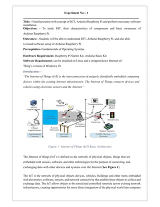
Figure: 1. Internet of Things (IoT) Basic Architecture
The Internet of things (IoT) is defined as the network of physical objects, things that are
embedded with sensors, software, and other technologies for the purpose of connecting and
exchanging data with other devices and systems over the Internet (See Figure 1).
The IoT is the network of physical objects devices, vehicles, buildings and other items embedded
with electronics, software, sensors, and network connectivity that enables these objects to collect and
exchange data. The IoT allows objects to be sensed and controlled remotely across existing network
infrastructure, creating opportunities for more direct integration of the physical world into computer
2. based systems, and resulting in improved efficiency, accuracy and economic benefit, when IoT is
augmented with sensors and actuators, the technology becomes an instance of the more general class
of cyber physical systems, which also encompasses technologies such as smart grids, smart homes,
intelligent transportation and smart cities. Each thing is uniquely identifiable through its embedded
computing system but is able to interoperate within the existing Internet infrastructure.
So, Internet of Things or IoT is an architecture that comprises specialized hardware boards, Software
systems, web APIs, protocols which together creates a seamless environment which allows smart
embedded devices to be connected to internet such that sensory data can be accessed and control
system can be triggered over internet.
Also devices could be connected to internet using various means like Wi-Fi, Ethernet and so on.
Furthermore, devices may not needed to be connected to the internet independently, rather than
creating a cluster of devices such as a sensor network and the base station, or the cluster head could
be connected to the internet. This leads to more abstract architecture for communication protocols
which ranges from high level to low level.
Most interestingly, these devices must be uniquely discovered. For unique discovery of the
devices in a Network, they need to have unique IP address. IoT devices essentially have
IPv6 addressing scheme. All these devices have either fixed or Subnet masked IP addresses
of type v6. Unique IP addresses makes IoT devices discoverable in the internet as
independent node. This is the most important concept to have in mind to understand IoT.
Since IoT are essentially embedded systems and smart objects connected to internet with
unique IP address which can be discovered and communicated over internet. We have also
seen that the IoT devices may have external peripheral like Actuators and Sensors.
Embedded Platform
Arduino---is probably the best starting point for embedded based IoT. Basic Arduino Boards don't
come with Ethernet shield or Wi-Fi shield and for Arduino to be able to work as IoT device, their
need to select Arduino with Ethernet shield or Wi-Fi shield. Arduino run on the other hand is a board
that comes ported with Ethernet shield.
Raspberry Pi ---is probably one of the best things to happen in DIY (Do it yourself) IoT. A wide
range of Data driven applications like Home Automation Server to Home Multimedia server, File
Server can be developed with Pi. PI like Arduino has general purpose IO pins. But seamless
working with sensors is bit tedious in Pi. Another efficient IoT board is Intel Edition which has
integrated BLE, WiFi among host of other features. It supports wide range of Industry standard
hardware (over 30) through 70-pin interface (See Figure 2).
Intel Galileo--- is another good offering by Intel which supports the same shielding that of
Arduino Uno. So it can be said to be first Intel powered device which is Arduino compatible.
3. It has among other thing a USB host controller like Raspberry Pi which makes this an attractive
hardware. Galileo also has Ethernet shield in built.
Description of Raspberry Pi 3 Model B-
1. CPU: Raspberry Pi 3 uses Broadcom BCM2837 SOC 64-bit quad-core ARM
Cortex A53 (ARMv8 CPU) with 512KB shared L2 cache.
2. Memory: Provided with 1 GB of RAM
3. Wi-Fi Support: 802.11n Wireless LAN
4. Bluetooth: Supports Bluetooth 4.1 Bluetooth Low Energy (BLE)
5. USB Ports: 4-USB ports which allow attaching four different USB devices like keyboard,
mouse, etc.
Figure: 2. Raspberry Pi 3 Model B Block Diagram
4. 6.Ethernet Port: Standard Ethernet port to quickly setup and access internet. This can be very
useful when we want to setup raspberry pi for the first time without a monitor.
7.GPIO Pins: Raspberry Pi 3 supports 40 GPIO Pins General Purpose Input Output. These digital
input/output pins can be used to drive LED, Switches, and Sensors etc.
8.Full HDMI Port: Support HDMI port (High-Definition Multimedia Interface) which can be
used to quickly connect raspberry pi to HDMI Monitor. With HDMI Cable and Monitor we can
add Screen to Raspberry Pi.
9.Micro SD card slot: The Micro SD Card will hold the operating system which will boot while we
power on Raspberry Pi 3.
10. Audio/Video: Combined 3.5mm audio jack and composite video
11. Display interface (DSI): enable us to interface Display Module
12. Camera interface (CSI): enable us to interface Camera Module
13. Graphics Support: VideoCore IV 3D graphics core for advance graphics capabilities.
Raspberry Pi Downloads - Software for the Raspberry Pi
Raspberry Pi OS(previously called Raspbian) is our official operating system for all
models of the Raspberry Pi.
Use Raspberry Pi Imager for an easy way to install Raspberry Pi OS and other operating systems
to an SD card ready to use with your Raspberry Pi:
a.Raspberry Pi Imager for Windows
b.Raspberry Pi Imager for macOS
c.Raspberry Pi Imager for Ubuntu
Version: 1.4
Install Raspberry Pi Imager to Raspberry Pi OS by running
6. Ethernet Port: Standard Ethernet port to quickly setup and access internet. This can useful
when we want to setup raspberry pi for the first time without a monitor.
7.GPIO Pins: Raspberry Pi 3 supports 40 GPIO Pins General Purpose Input Output. These digital
input/output pins can be used to drive LED, Switches, and Sensors etc.
8.Full HDMI Port: Support HDMI port (High-Definition Multimedia Interface) which can be
used to quickly connect raspberry pi to HDMI Monitor. With HDMI Cable and
Monitor we can add Screen to Raspberry Pi.
9.Micro SD card slot: The Micro SD Card will hold the operating system which will boot while we
power on Raspberry Pi 3.
10. Audio/Video: Combined 3.5mm audio jack and composite video
11. Display interface (DSI): enable us to interface Display Module
5. 12. Camera interface (CSI): enable us to interface Camera Module
13. Graphics Support: VideoCore IV 3D graphics core for advance graphics capabilities.
Raspberry Pi Downloads - Software for the Raspberry Pi
Raspberry Pi OS(previously called Raspbian) is our official operating system for all
models of the Raspberry Pi.
Use Raspberry Pi Imager for an easy way to install Raspberry Pi OS and other operating
systems to an SD card ready to use with your Raspberry Pi:
a. Raspberry Pi Imager for Windows
b. Raspberry Pi Imager for macOS
c. Raspberry Pi Imager for Ubuntu
Version: 1.4
Install Raspberry Pi Imager to Raspberry Pi OS by running sudo apt install rpi-imager in a
terminal window
Recovery
If your Raspberry Pi 4 will not boot, it is possible that the SPI EEPROM has become
corrupted. Tocheck, remove the SD card, disconnect the device from power, then reconnect
it. If the green LED does not flash, this indicates that the EEPROM has become corrupted.
Raspberry Pi Imager provides an easy way to fix this problem, by automatically preparing an SD
card that will reprogram your Raspberry Pi 4’s EEPROM:
1. Find an SD card that is empty, or does not contain any data you want to keep; it will be
completely erased of all data during this process.
2. Download Raspberry Pi Imager for your operating system from the list near the top of
this page.
3. Click “CHOOSE OS” and select “Misc utility images” then “Pi 4 EEPROM boot
recovery”.
4. Insert an SD card, click “CHOOSE SD CARD”, select the card you have inserted, then
click “WRITE”.
5. Once the SD card is ready, insert it into your Raspberry Pi 4 then connect the Raspberry Pi
to power.
6. Once complete, the green LED will blink rapidly in a steady pattern. Disconnect the
device from power. Now you can remove the recovery SD card, insert your usual SD card,
and resume using your Raspberry Pi.
Alternatively, you can download the bootloader and create a recovery SD card manually:
6. 1. Download the bootloader.
2. Extract it to an empty FAT-formatted SD card and insert it into your Raspberry Pi 4.
3. Connect the power and wait for the green LED to flash quickly.
Raspberry Pi Desktop (for PC and Mac)
Debian with Raspberry Pi Desktop is the Foundation’s operating system for PC and
Mac. You can create a live disc, run it in a virtual machine, or even install it on your
computer.
Connecting a Raspberry Pi to aLaptop Display
After purchasing a Raspberry Pi and an SD card, you might not feel like going out and
buying a display, mouse, and keyboard just to create a simple project. No worries!
Together, a laptop and an internet connection are sufficient to get started on your
Raspberry Pi. How?
1. Make Sure the OS Is Installed on the SD Card
Your SD might have Raspberry Pi Operating System installed. Otherwise, you can easily
download the Raspbian Operating System and install it on a blank SD card.
For the rest of this tutorial, I will be assuming that your SD card has the Raspbian operating
system installed.
2. Configure the Wifi Connection on Your SD Card
Now you’re ready to configure your SD card so that, on boot, your Raspberry Pi will connect
to a wifi network. Once the Raspberry Pi is connected to a network, you can then access its
terminal via SSH.
Insert your SD card into your laptop. You should see a /boot file folder show up. First, create
a file named wpa_supplicant.conf in the /boot folder.
Information like accepted networks and pre-configured network keys (such as a wifi password)
can be stored in the wpa_supplicant.conf text file. The file also configures wpa_supplicant—
the software responsible for making login requests on your wireless network. So, creating the
wpa_supplicant.conf file will configure how your Raspberry Pi connects to the internet.
The contents of your wpa_supplicant.conf file should look something like this:
ctrl_interface=DIR=/var/run/wpa_supplicant GROUP=netdev update_config=1
country=US
network={
ssid="YOURSSID"
psk="YOURPASSW
7. ORD"
scan_ssid=1
}
The first line means “give the group ‘netdev’ permission to configure network interfaces.” This
means that any user who is part of the netdev group will be able to update the network
configuration options. The ssid should be the name of your wifi network, and the psk should be
your wifi password.
After creating and updating the wpa_supplicant.conf file, add an empty SSH file in /boot. This
SSH file should not have any file extensions. When the Rasperry Pi boots up, it will look for the
SSH file. If it finds one, SSH will be enabled. Having this file essentially says, “On boot, enable
SSH.” Having SSH will allow you to access the Raspberry Pi terminal over your local network.
3. Turn on Your Raspberry Pi
Put the SD card back in the Raspberry Pi. Power on.
4. Connect to Your Raspberry Pi with SSH
Make sure your laptop is on the same network as the Raspberry Pi (the network in the
wpa_supplicant.conf file). Next, you’ll want to get the IP address of the Raspberry Pi on the
network. Run arp -a to see IP addresses of other devices on your network. This will give you a
list of devices and the corresponding IP and MAC addresses. You should see your Raspberry Pi
listed with its IP address.
Connect to the Raspberry Pi by running ssh pi@[the Pi's IP Address]. If this is your first time
logging in, the default password should be “raspberry.” You can configure your own custom
password after the first login.
You should now have access to your Raspberry Pi command line.
5. Install VNC Server
Now you have access to your Raspberry Pi terminal, but how do you see the Raspberry Pi desktop?
You’ll need to install a VNC server. Running a VNC server on your Raspberry Pi allows you to
control your Raspberry Pi desktop remotely on a laptop (the VNC viewer).
Realvnc-vnc-server worked well for me. To install, copy the following into the terminal:
sudo apt–get update
sudo apt–get install realvnc–vnc–server realvnc–vnc–viewer
After installing the VNC server, you will need to enable it:
• type sudo raspi-config in your terminal
• A pop-up will appear; navigate to 5 “Interfacing Options”
• Navigate to “P3 VNC”
• Select “Yes”
8. Raspberrypi.org also provides a step-by-step guide on how to do this.
6. Install a VNC Viewer on Your Laptop
I installed VNC Viewer from RealVNC.
After installation, launch VNC Viewer, and type in the IP address of your Raspberry Pi
as the VNC server address. If you’ve forgotten its IP address, just run arp -a again. VNC
Viewer will then prompt you for the Raspberry Pi default credentials. If you have not yet
configured them, the default username is “pi,” and the default password is “raspberry.”
Congratulations! You should see your Raspberry Pi desktop!
9. Experiment No: - 2
----------------------------------------------------------------------------------------------------
Title: - Study of different operating systems for Raspberry-Pi /Beagle board.
Understanding the process of OS installation on Raspberry-Pi /Beagle board
Objectives: -
To study various supporting OS platforms for Raspberry-Pi /Beagle board
Outcomes: -
Students will able to understand the different supporting OS platforms of
Raspberry-Pi /Beagle board
Prerequisites:-
Fundamentals of Operating Systems
Fundamentals of Computer
Organization
Hardware
Requirement:-
Raspberry Pi Starter
Kit Unit of Beagle
Black Board
Software Requirement:- Windows 7 64 Bit or Higher / Ubuntu 16.04 or
Higher Raspberry Pi Desktop
RASPBIAN
Introduction:
• Operating Systems for Single Board Computers
◦Single board computers support a wide range of operating system software. The purpose
of the operating system is to allow control of and interaction with a single board computer
and to provide a framework of system services (Disk I/O, Communications, memory
management, scheduling, etc) on which to run applications.
◦ The major types of operating system software are:
▪ Real-time operating systems (RTOS)
10. ▪ Embedded LINUX
▪ Desktop Linux
▪ Embedded Windows
▪ Desktop Windows
▪ Roll your own or in-house
▪ UNIX
▪ Sun Solaris
▪ BSD
◦ Desktop Operating Systems
▪ Desktop Operating systems (Windows and LINUX) are used in products such as Kiosks
and point of sale (POS) terminals as well as for general purpose computing. Desktop
Operating Systems make no guarantees about speed or responsiveness to real world
events. Mission critical systems (systems that can’t be allowed to fail) are usually not
built using desktop operating systems.
◦ Soft Real Time or Non-Realtime Operating Systems
▪ Embedded operating systems such as Embedded Linux or Embedded
Windows are often used to power so-called “intelligent products” such as cell
phones, home electronics and Flat screen TV sets.
▪ These devices do not require hard real-time response to computing
deadlines. Response times are often dependent on system load and as such
cannot be guaranteed. These operating systems support other embedded
features such as instant ON/Boot to make them more suitable for embedded
devices.
Real-Time Operating Systems (RTOS)
▪ Real-Time simply means that a response must be correct and must meet a timing
deadline every time or the systems has failed.
▪ Real Time operating Systems are used for the same types of embedded devices as
Embedded LINUX, and Embedded Windows but due to their ability to meet hard timing
and response deadlines, can also be used for controlling things like industrial
instruments, anti-lock braking systems etc. Real-time operating systems will guarantee
11. a response to an interrupt or the completion of a system call in all cases, regardless of
the load on the system.
◦ Roll your Own or In-House System Software
▪ Some Single Board Computer applications do not use an operating system. This may
be because the system must be hand-optimized to meet tight real-time requirements or
because it does not require the services (and attendant overhead) that an operating
system brings. In these cases, engineers will write all the code required to run their
embedded application using an embedded compiler and assembler. These embedded
systems are typically written in C, C++, and assembler.
• Operating System for Raspberry Pi
◦ The software offered are RASPBIAN, PIDORA, OPENELEC, RASPBMC, RISC OS,
ARCH LINUX. All this software can be downloaded easily and for free from the official
forum under the NOOBS (new out of the box software) category.
◦ It provides support for functioning and coding in Python as the main
programming language. It also provides support for BASIC, C, C++, JAVA, Perl and Ruby.
◦ Booting Process
▪ Since the board has been designed with curious school children in mind, it’s easy to
use. The booting method involves the following steps:
i. Downloading the NOOBS operating system install manager from the official forum of
Raspberry Pi.
ii. Formatting a microSD card.
iii. Burning the NOOBS image onto a microSD card.
iv. Inserting the card into the microSD card slot on the RaspberryPi board.
v. Plugging in keyboard, mouse and monitor cable onto the board and to the monitor
vi. Plugging in the USB power cable.
vii. The boot process has now begun and a configuration window appears to enable the
camera module if present and setting the date and time.
viii. The command line interface loads up asking for the username and password, upon
submitting successful information the board is fully operational.
ix. The graphical user interface can be chosen by typingstartx.
12. x. Default username and passwords for first boot are: username: pi, password: raspberry.
▪ After the booting process the board can be utilized for anyproject.
Beagle Board
Step #0. A: Download the latest software image
o Download the latest Debian image from beagleboard.org/latest- images. The "IoT"
images provide freer disk space if you don't need to use a graphical user interface (GUI).
o Note: Due to sizing necessities, this download may take 30 minutes or more.
o The Debian distribution is provided for the boards. The file you download will have an
.img.xz extension. This is a compressed sector-by-sector image of the SD card.
Step #0.B: Install SD card programming utility
o Download and install Etcher.
o Some general help on programming SD cards can be found on the Ubuntu Image Writer page.
13.
14. Step #0.C: Connect SD card to your computer
o Use your computer's SD slot or a USB adapter to connect the SD card to your computer.
Step #0. D: Write the image to your SD card
o Use Etcher to write the image to your SD card. Etcher will transparently decompress
the image on-the-fly before writing it to the SD card.
Step #0.E: Eject the SD card
o Eject the newly programmed SD card.
Step #0.F: Boot your board off of the SD card
o Insert SD card into your (powered-down) board, hold down the USER/BOOT button (if using
Black) and apply power, either by the USB cable or 5V adapter.
o If using an original Beagle Bone or Pocket Beagle, you are done.
o If using Beagle Bone Black and desire to write the image to your on-board eMMC, you'll need
to follow the instructions at
http://elinux.org/Beagleboard:BeagleBoneBlack_Debian#Flashing_eMMC. When the flashing
is complete, all 4 USRx LEDs will be steady on or off. The latest Debian flasher images
automatically power down the board upon completion. This can take up to 45 minutes. Power-
down your board, remove the SD card and apply power again to finish.
Step 1: Power and boot
o Most Beagles include a USB cable, providing a convenient way to provide both power to your
Beagle and connectivity to your computer. If you provide your own, ensure it is of good quality.
You'll connect the "type-B" plug of the USB cable to your Beagle and the "type-A" plug to your
computer. Note that BeagleBoard-X15 must always be powered instead by a 12V adapter with
a barrel jack.
o Alternatively, for Beagles other than BeagleBoard-X15 and Beagle Bone Blue that
require 12V, you can utilize a 5V adapter connected to the barrel jack.
o If your Beagle was provided with an SD (microSD) card, make sure it is inserted ahead of
15. providing power. Most Beagles include programmed on-board flash and therefore do not
require an SD card to be inserted.
o You'll see the power (PWR or ON) LED lit steadily. Within a minute or so, you should see
the other LEDs blinking in their default configurations.
USR0 is typically configured at boot to blink in a heartbeat pattern
USR1 is typically configured at boot to light during SD (microSD) card accesses
USR2 is typically configured at boot to light during CPU activity
USR3 is typically configured at boot to light during eMMC accesses
WIFI is typically configured at boot to light with Wi-Fi network association (Beagle
Bone Blue only)
tep 2: Enable a network connection
o If connected via USB, a network adapter should show up on your computer. Your
Beagle should be running a DHCP server that will provide your computer with
an IP address of either 192.168.7.1 or 192.168.6.1, depending on the type of USB
network adapter supported by your computer's operating system. Your Beagle
will reserve 192.168.7.2 or 192.168.6.2 for itself.
o If your Beagle includes Wi-Fi, an access point called "Beagle Bone-XXXX" where
"XXXX" varies between boards. The access point password defaults to "Beagle
Bone". Your Beagle should be running a DHCP server that will provide your
computer with an IP address in the 192.168.8.x range and reserve 192.168.8.1
for itself.
16. o If your Beagle is connected to your local area network (LAN) via either Ethernet or
Wi-Fi, it will utilize mDNS to broadcast itself to your computer. If your computer
supports mDNS, you should see your Beagle as beagle bone. local. Non-
BeagleBone boards will utilize alternate names. Multiple Beagle Bone boards on
the same network will add a suffix such as beaglebone-2.local.
o The below table summarizes the typical addresses and should dynamically update to
indicate an active connection. Note that you must load this page without HTTPS
security for the automatic detection to work
IP Address Connection Type Operating
System(s)
Status
192.168.7.2 USB Windows Inactive
192.168.6.2 USB Mac OS X, Linux Inactive
192.168.8.1 WiFi All Inactive
beaglebone.local all mDNS enabled Inactive
beaglebone-2.local all mDNS enabled Inactive
o With the latest images, it should no longer be necessary to install drivers for your operating system
to give you network-over-USB access to your Beagle. In case you are running an older image, an
older operating system or need additional drivers for serial access to older boards, links to the old
drivers are below.
17. Operating
System
USB
Drivers
Comments
Windows (64-
bit)
64-bit
installer
If in doubt, try the 64-bit installer first.
o Note #1: Windows Driver Certification
warning may pop up two or three times. Click
"Ignore", "Install" or "Run"
o Note #2: Tocheck if you're running 32 or 64-
bit Windows see this:
support.microsoft.com/kb/827218.
o Note #3: On systems without the latest
service release, you may get an error
(0xc000007b). In that case, please install the
following and retry: www.microsoft.com/en-
us/download/confirmation.aspx?id=13523.
o Note #4: You may need to reboot Windows.
o Note #5: These drivers have been tested to
work up to Windows 10
Windows (32- bit) 32-bit
installe
r
Mac OS X Network
Serial
Install both sets of drivers.
Linux mkudevrule.
sh
Driver installation isn't required, but you might find a
few
udev rules helpful.
o Note: Additional FTDI USB to serial/JTAG information and drivers are available from
www.ftdichip.com/Drivers/VCP.htm.
o Note: Additional USB to virtual Ethernet information and drivers are available from
www.linux-usb.org/gadget/ and joshuawise.com/horndis.
Step 3: Browse to your Beagle
o Using either Chrome or Firefox (Internet Explorer will NOT work), browse to the web server
running on your board. It will load a presentation showing you the capabilities of the board.
Use the arrow keys on your keyboard to navigate the presentation.
o Click here to launch: http://192.168.7.2
o Older software images require you to EJECT the BEAGLE_BONE drive to start the
network. With the latest software image, that step is no longer required.
18. o Troubleshooting
Do not use Internet Explorer.
Virtual machines are not recommended when using the direct USB
connection. It isrecommended you use only network connections to
your board if you are using a virtual machine.
When using 'ssh' with the provided image, the username is 'debian' and the
password
is 'temppwd'.
Visit beagleboard.org/support for additional debugging tips.
o Other currently available software images
Some of the starting images below involve multiple steps to produce
an SD cardimage or otherwise change some of the steps above, so be
sure to read all the instructions on their pages. Choose the starting
point you want, download or produce the SD card image and follow
the steps above.
At the time of release, not all of these distributions support BeagleBone
Black, but
should soon.
Texas Instruments releases: Android, Linux, StarterWare (no OS)
Linux: Debian, Angstrom Distribution, Ubuntu, ArchLinux, Gentoo,
Sabayon, Buildroot,Erlang, Fedora
Other: QNX, FreeBSD
19. Experiment No: - 3
----------------------------------------------------------------------------------------------------
Title : Study of Connectivity and configuration of Raspberry-Pi /Beagle board circuit with
basic peripherals, LEDS. Understanding GPIO and its use in program.
Objectives: -
• To study the fundamentals of connectivity schemes of Raspberry-Pi /Beagle board.
• To study the configuration of with basic peripherals, LEDS
• To understand the GPIO pins of Raspberry-Pi 3
• To understand the concept of Led bar
• To understand the common anode & common cathode configuration.
• To interface LED bar with Raspberry Pi.
• Generate various patterns on LED bar.
Outcomes: -
• Students will able to use Raspberry-Pi /Beagle board circuit with external resources.
• To program the GPIO pins of Raspberry-Pi 3 using Python
Prerequisites-
• Fundamentals of Operating Systems
• Fundamentals of Computer Organization
Hardware Requirement-
• Raspberry Pi Starter Kit
• Unit of Beagle Black Board
• LEDs
• Breadboard
• 5V Power Supply
Software Requirement-
• Windows 7 64 Bit or Higher / Ubuntu 16.04 or Higher
• Raspberry Pi Desktop
• RASPBIAN
• BeagleBone
• GCC 6.0 of Higher / Python 3.0 or Higher
20. Introduction :-
• Raspberry Pi 3 Model B is the latest version of raspberry pi board.
• It is released on 29 February.
• The above figure shows the Raspberry Pi 3 Model B and It’s GPIO pins
• General-purpose input/output (GPIO) is a generic pin on an integrated circuit or computer
• board whose behavior—including whether it is an input or output pin—is controllable by
the user at run time.
• There are 40 pins available on board of Raspberry pi 3 model B.
• The Pins are arranged in a 2×20 fashion as shown in the figure above
• Out of these, 26 pins are GPIO pins
• As you can observe, the numbers to the pins are given in zigzag manner.
• The first (bottom) row starts with number ‘1’. So the pins in this row have odd numbers i.e.
• from 1 to 39.
21. • The 2 nd (Top) row starts with number ‘2’. So the pins in this row have even numbers i.e.
• from 2 to 40.
• Out of 40 pins,
1. 26 pins are GPIO pins,
2. 8 pins are Ground (GND) pins,
3. 2 pins are 5V power supply pins
4. 2 pins are 3.3V power supply pins
5. 2 pins are not used
• Now if you’re coming to the Raspberry Pi as an Arduino user, you’re probably used to
• referencing pins with a single, unique number.
• In Raspberry Pi there are two different numbering schemes for referencing Pi pin numbers:
1. Broadcom chip-specific pin numbers (BCM)
2. Physical pin numbers (BOARD)
• You’re free to use either number-system.
• The programs require that you declare which scheme you’re using at the very beginning of
your program.
• In a program, at a time, you can use only one number scheme.
Broadcom chip-specific pin numbers (BCM)
• BCM - Broadcom pin number, commonly called "GPIO", these are the ones you probably
• want to use with RPi.GPIO
• The parameter used for this system is (GPIO.BCM).
• This is a lower level way of working - it refers to the channel numbers on the Broadcom
SOC.
• To use this system, you have to always work with a diagram describing which channel
• number goes to which pin on the RPi board.
• Your script could break between revisions of Raspberry Pi boards.
• In this system
• a. 26 GPIO pins are named as GPIO 01 to GPIO 26Physical Numbering System (BOARD)
Physical Numbering System (BOARD)
• This system uses physical - Numbers corresponding to the pin's physical location on the
22. • header
• The numbers printed on the board are physical numbering system.
• The parameter used for this system is (GPIO.BOARD).
• The advantage of using this numbering system is that your hardware will always work,
• regardless of the board revision of the RPi.
• You will not need to rewire your connector or change your code.
• In this system
• a. 26 GPIO pins are named between 0 to 40
The below table summarizes the pinout of Raspberry-Pi in both the number systems.
The Python IDLE shell and command line
To use the Python IDLE IDE for programming in Raspberry-Pi use the following
• Open Python 3 from the main menu:
23. • Or open terminal window and type the command sudo idle 3.5 and press enter
• Install all libraries required for Buzzer as given above.
• Write the program as per algorithm given below
• Save with Ctrl + S and run with F5.
• See output on Python Shell or Terminal Window.
Raspberry Pi GPIO programming using Python
• The Raspberry Pi is often used in conjunction with other hardware to create interesting
electronic projects.
• The Pi 3 comes with 40 GPIO pins that you can use to interface with various hardware
devices—for both receiving data from them or for writing data to them.
• To do this, we have to program the GPIO pins. To do this, special libraries in Python are
used.
• To include these libraries in the program, the command used is ‘import’
• This way, we can write applications to both read and also to control devices, i.e., turn them
on and off, etc
24. The default operating system used in Raspberry-Pi is Raspbian.
• The Python package used for Raspberry Pi GPIO programming is RPi.GPIO. It is already
installed in Raspbian.
• If you are using any other operating system, the package can be installed by using the
following command:
$ sudo pip install RPi.GPIO
• There are important 8 steps in the programming of Raspberry-Pi using Python as follows
1. Import the RPi.GPIO library using the following command
import RPi.GPIO as GPIO
2. Import the Time library using the following command
import time
3. Set numbering scheme to be used. The method used for this is
GPIO.setmode(). We will use physical number scheme. So the method is
written as
GPIO.setmode(GPIO.BOAD)
4. Set the pin mode as INPUT or OUTPUT using the commands
GPIO.setup(channel, GPIO.IN) GPIO.setup(channel,
GPIO.OUT)
5. Read input using following command
GPIO.input(pin no)
6. Write output using following comman
GPIO.output(pin no, state)
7. Give delay using command using following command
time.sleep(1) # delay for 1 second
8. Clean up GPIO and exit using following commands
GPIO.cleanup() print(“Exiting...”)
• You must clean up the pin set-ups before your program exits otherwise those pin settings
will persist, and that might cause trouble when you use the same pins in another program.
• The Pi ‘expresses its displeasure’ with a warning.
• To clean up the entire set of pins, invoke GPIO.cleanup().
• If you want only a few pins to be cleaned up, then the pin numbers should be
provided as GPIO.cleanup (channel_list).
• Anyway, you can suppress the warning messages by calling GPIO.setwarnings (False).
25. • Save the program with proper name. The file is saved with extension ‘.py’.
• The IDE named ‘IDLE’ used for programming is an interpreter and not a
compiler. So to run the python program, we need to give the super user
permission as follows.
Introduction to “LED”
• LED is a Light Emitting Diode.
• Light emitting diode is a two lead semiconductor light source. It is a p-n junction diode,
which emits light when it is activated.
• When a suitable voltage is applied to the leads, electrons are able to recombine with
electron holes within the device, and the color of light (corresponding to the energy of
photon) is determined by the energy band gap of the semiconductor.
• It has two terminals named as ‘anode (+ve)’ and ‘cathode (-ve)’.
• Battery is connected to these two terminals.
• When LED is forward biased, it emits light.
• In LED bar number of LEDs are connected in series (in our case 8 LEDs are connected)
• LED bar has two configurations as
• Common Anode: In this, anode terminal of all the LEDs are made common and connected to
the VCC (+5v). By controlling cathode terminal we can make LED ON or OFF (current
sourcing).
• Common Cathode: In this, cathode terminal of all the LEDs are made common and
• connected to the Ground (0v). By controlling anode terminal we can make LED ON or OFF
• (current sinking).
26. Safety precautions:
• Raspberry-Pi provides 3.3V and 5V VCC pins
• Raspberry-Pi operates on 3.3V.
• Various sensors and actuators operate on different voltages.
• Read datasheet of a given sensor or an actuator and then use appropriate VCC pin to
connect a sensor or an actuator.
• Ensure that signal voltage coming to the Raspberry-Pi from any sensor or actuator does not
exceed 3.3V.
• If signal/data coming to Raspberry-Pi is greater than 3.3V then use voltage level shifter
module to decrease the incoming voltage.
• The Raspberry-Pi is a costly device, hence you should show the circuit connections to
your instructor before starting your experiment.
27. Mathematical model:
Steps in Algorithm
UML Diagram/Dataflow/Flowchart
Start
Fetch GPIO and
Time Libraries
Pin 18=HIGH
LED Is off
LED glow
Read Input From Pin 18 ,
set as O/P
29. Outputs
Digital Output
• To write a pin high or low, use the GPIO.output([pin],
[GPIO.LOW, GPIO.HIGH]) function. For example, if you want to
set pin 18 high, write:
COPY CODEGPIO.output(18, GPIO.HIGH)
• Writing a pin to GPIO.HIGH will drive it to 3.3V, and
GPIO.LOW will set it to 0 V. For the lazy, alternative to
GPIO.HIGH and GPIO.LOW, you can use either 1, True, 0 or
False to set a pin value.
Assignment Question:
1. Enlist the possible applications of using combinations
through GPIO pins of RPi. References: -
https://learn.sparkfun.com/tutorials/raspberry-
gpio/gpio-pinout
https://makezine.com/projects/tutorial-raspberry-pi-
gpio-pins-and-python/
Conclusion:
Hence, we have successfully learnt about the various GPIO pins in
Raspberry Pi with small application of lightning LED
30. Experiment No: - 4
----------------------------------------------------------------------------------------------------
Title: - Use of Temperature Sensor and LED bar.
Objective: - Understanding the connectivity of Raspberry-Pi /Beagle board circuit
with temperature sensor. Write an application to read the environment temperature. If
temperature crosses a threshold value, the application indicated user using LEDs.
Hardware Requirement: - 1) Raspberry Pi.
2) DHT 11 Sensor.
3) LED Bar or Pizzo Buzzer.
Software Requirement: - 1) Python IDLE 2.0 or 3.0
2) Adafruite Libraries.
Theory: -
1) The DHT11 temperature and humidity sensor is a nice little module that
provides digital temperature and humidity readings. It’s really easy to set up, and
only requires one wire for the data signal.
2) These sensors are frequently used in remote weather stations, soil monitors, and
home environment control systems. The programming is simple too, and many
libraries and example code in both Python and C already exist.
3) The DHT11 contains a surface mounted NTC thermistor and a resistive
humidity sensor. An IC on the back of the module converts the resistance
measurements from the thermistor and humidity sensor into digital outputs of
degrees Celsius and Relative Humidity.
DHT 11 Sensor:-
1) 3 to 5V power and I/O.
2) 2.5mA max current use during conversion (while requesting data).
3) Good for 20–80% humidity readings with 5% accuracy.
4) Good for 0–50°C temperature readings ±2°C accuracy.
5) No more than 1 Hz sampling rate (once every second).
6) Body size 15.5mm x 12mm x 5.5mm.
7) 4 pins with 0.1" spacing.
There are two variants of the DHT11 you’re likely to come across. One is a four pin stand
alone module, and the other is a three pin, PCB mounted module. The pinout is different for
each one, so connect the DHT11 according to which one you have.
Programming the DHT11 in Python :-
We will be using the Adafruit DHT11 Python library. We can download the library using Git,
so if you don’t have Git installed on your Pi already, enter this at the command prompt:
sudo apt-get install git-core
Note: If you get an error installing Git, run sudo apt-get update and try it again.
Install the Adafruit DHT11 library:-
1. Enter this at the command prompt to download the library: git clone
https://github.com/adafruit/Adafruit_Python_DHT.git
2. Change directories with:
cd Adafruit_Python_DHT
31. 3. Enter this:
sudo apt-get install build-essential python-dev
4. Install the library with:
sudo python setup.py install
Conclusion:-
Print-Out
Program:
Program of DHT-11 with Pizzo Buzzer: -
# Download Adafruit_DHT from github
DHT11 #install it using "sudo python
setup.py install" #!/usr/bin/python
import sys
import Adafruit_DHT
import RPi.GPIO as
GPIO import time
GPIO.setmode(GPIO.BCM)
GPIO.setwarnings(False)
GPIO.setup(23,GPIO.OUT)
while True:
hum,temp=Adafruit_DHT.read_retry(1
1,4) print(hum,temp)
if(temp>=25):
print("buzzer
on")
GPIO.output(21,GPIO.HIGH)
Circuit Diagram – DHT11:-
32. • VCC of DHT11 -> 5v Pin of Raspberry Pi 3
• GND of DHT11 -> GND Pin of Raspberry Pi 3
• Signal pin of DHT11 -> GPIO 4 Pin of Raspberry Pi3
DHT-11 Sensor:-
34
33. Experiment No: - 5
-----------------------------------------------------------------------------------------------------------
Title:- Use of IR(Infra red) Sensor and LED bar
Objective:- Understanding the connectivity of Raspberry-Pi /Beagle board circuit
with IR sensor. Write an application to detect obstacle and notify user using LEDs.
Hardware Requirement :-
1) Raspberry Pi.
2) IR Sensor.
3) LED Bar or Pizzo Buzzer.
Software Requirement:-
1) Python IDLE 2.0 or 3.0
Theory:-
1) An infrared sensor is an electronic instrument which is used to sense certain
characteristics of its surroundings by either emitting and/or detecting infrared
radiation.
2) Infrared sensors are also capable of measuring the heat being emitted by an object
and detecting motion.
3) Infrared waves are not visible to the human eye. In the electromagnetic spectrum,
infrared radiation can be found between the visible and microwave regions.
4) The infrared waves typically have wavelengths between 0.75 and 1000μm.
IR Sensor functionality:-
35. Program:-
import RPi.GPIO as
GPIO import time
GPIO.setmode(GPIO.BCM)
GPIO.setwarnings(False)
GPIO.setup(18,GPIO.IN)
GPIO.setup(21,GPIO.OUT)
try:
while True:
i=GPIO.input(
18) if i==1:
print(" No Obstacle")
print("buzzer OFF")
GPIO.output(21,GPIO.L
OW)
time.sleep(1)
elif i==0:
print("Obstacle Found")
print("buzzer ON")
GPIO.output(21,GPIO.HI
GH)
time.sleep(1)
except
KeyboardInterrupt:
GPIO.cleanup()
36. Experiment No: - 6
-----------------------------------------------------------------------------------------------------------------------
Title:- Use of Camera.
Objective:- Understanding and connectivity of Raspberry-Pi /Beagle board with
camera. Write an application to capture and store the image.
Hardware Requirement :-
1) Raspberry Pi.
2) Camera
Software Requirement:-
1) Python IDLE 2.0 or 3.0
Theory:-
1)The Raspberry Pi Camera Module v2 replaced the original Camera Module in April 2016.
2) The v2 Camera Module has a Sony IMX219 8- megapixel sensor (compared to the 5-
megapixel OmniVision OV5647 sensor of the original camera).
3) The Camera Module can be used to take high- definition video, as well as stills
photographs. It’s easy to use for beginners, but has plenty to offer advanced users if you are
looking to expand your knowledge.
4) You can also use the libraries we bundle with the camera to create effects.
5) You can read all the gory details about IMX219 and the Exmor R back-illuminated sensor
architecture on Sony’s website, but suffice to say this is more than just a resolution upgrade:
it’s a leap forward in image quality, colour fidelity, and low-light performance.
6) It supports 1080p30, 720p60 and VGA90 video modes, as well as still capture. It attaches
via a 15cm ribbon cable to the CSI port on the Raspberry Pi.
7) The camera works with all models of Raspberry Pi 1, 2, and 3.
8) It can be accessed through the MMAL and V4L APIs, and there are numerous third- party
libraries built for it, including the Picamera Python library.
9) The camera module is very popular in home security applications, and in wildlife camera
traps.
Conclusion:
39. Program for Camera Preview:-
import picamera, time
camera = picamera.PiCamera()
camera.start_preview()
time.sleep(5) # hang for preview for 5
seconds camera.capture('snapshot.jpg')
camera.stop_preview()
Program to take videos:-
from picamera import
PiCamera import time
camera = PiCamera()
camera.resolution = (1280, 720)
camera.start_preview()
camera.annotate_text = "This is Tushar
Kute"
camera.start_recording('video.h264')
time.sleep(10)
camera.stop_recordi
ng()
camera.stop_preview
()
40. Experiment No: - 7
-----------------------------------------------------------------------------------------------------------------------
Title:- Use of X-Bee Module.
Objective:- Understanding and connectivity of Raspberry-Pi /Beagle board with
camera. Write an application to capture and store the image.
Hardware Requirement :-
1) Raspberry pi
2) Two X-bee modules
3) FRC cable
Software Requirement:-
1) Raspberry OS,
2) IDLE IDE for Python
3) XCTU for configuring X-bee
Theory:-
1) X-Bee is a low-power wireless mesh network standard, operating in the 2.4 GHz range.
2) XBee is not same as ZigBee—instead, XBee is a brand of radio
communication modules
(made byDigi) that can support a number of protocols, including ZigBee, 802.15.4,
WiFi, etc.
3) Its range is 10 to 100 meters.
4) X-Bee is often used in home automation products, though it is not the only
option. Configuration of X-bee modules:
To establish communication between two X-bees, they need to
configure. Step 1:
• To configure XBee module, connect XBee Explorer shield to a computer via USB.
41. Step 2:
Here we set the Channel, PAN ID, and Address values for the X-bee
Channel:
• The channel calibrates the operating frequency within the 2.4GHz 802.15.4 band.
• The XBees must be on the same channel to communicate with one another.
PAN ID (Personal Area Network ID):
• The X-Bees must share the same PAN ID to communicate with one another.
You can choose a value between 0 and 0xFFFF.
Addressing:
• Each X-Bee has a Source address (referred to as “MY address”) and a
Destination address (which has an upper half, Destination High or DH, and a
lower half, Destination Low or DL).
• The XBee’s destination address specifies to which source address it can send data.
• You can specify a universally unique address by using the 64-bit address
printed on the back of the module, use a shorter 16-bit address (unique within
a network), or use a string of text (e.g., “Alice’s radio”).
Additionally, each XBee in a network plays one of the following roles,
Coordinator:
• Each network has exactly one Coordinator, which serves as the root of the network tree.
Router:
• A network can have multiple Routers; these can forward information to end
devices and also run application functions.
Steps to configure the X-bee:
• Download and install XCTU. It is available for both Windows and Mac.
• Plug first XBee into an Explorer module, and connect it to computer’s USB
port via a USB cable.
• Open XCTU and click “Discover devices.”
42. • Select the port to be scanned. Then on the next page, select the
settings as shown below. Click “Finish.”
43. Your device should appear on the “Devices discovered” list.
• Click “Add selected devices” for your module
• With the Gear icon selected, click the radio module in the left-hand menu.
• This should open up a long list of settings.
44. • We can set the X-bee as Coordinator or Router.
• Plug the first X-bee on the Explorer. Set the first X-bee as
Coordinator and do the settings as per given in the below table.
• Now unplug the first X-bee and plug the second X-bee on the Explorer. Set the
second X-
bee as Router and do the settings as per given in the below table.
• After you’ve made all your changes,
click “Write.” Run the Communication
Test
• Plug one XBee (on its Explorer module) into a USB port (via USB cable).
• Plug the other XBee (on its Explorer module) into another USB port.
• In XCTU, scan for devices. You should see both devices available.
• Select both of them and click “Add selected devices.”
• Click one of the modules in the left-hand column. Now select the
Console icon to view the console. Click “Open.”
Co-ordinator Router
X-bee-1 X-bee-2
DH 0 0
DL FFFF 0
PAN ID 1234 1234
JV channel verification Disable Enable
CE Coordinator Enable Enable Disable
45. • Repeat for the other module, opening up a console.
• Type some text in one of the console. You should see the result
echoed back in the other console.
Safety precautions:
• Raspberry-Pi provides 3.3V and 5V VCC pins
• Raspberry-Pi operates on 3.3V.
• Various sensors and actuators operate on different voltages.
• Read datasheet of a given sensor or an actuator and then use
appropriate VCC pin to connect a sensor or an actuator.
• Ensure that signal voltage coming to the Raspberry-Pi from any sensor or
actuator does not
exceed 3.3V.
46. • If signal/data coming to Raspberry-Pi is greater than 3.3V then
use voltage level shifter module to decrease the incoming
voltage.
• The Raspberry-Pi is a costly device, hence you should show the circuit
connections to your
instructor before starting your experiment.
Set Up Your
Circuits For
Arduino:
• We will connect one X-bee to Arduino Microcontroller.
• This will act as sender
• The interfacing diagram of X-bee with Arduino is as shown below
Connections with
Arduino- Arduino Pins
X-bee
Pins
10 Data Out (Pin-2) (Tx)
11 Data In (Pin-3) (Rx)
3.3v Vcc or 3.3v (Pin-1)
G Gnd(Pin-10)
47. For Raspberry Pi:
Steps for assembling the circuit:
R-Pi-3 Pins X-bee Pins
10 Data Out (Pin-2) (Tx)
8 Data In (Pin-3) (Rx)
3.3v Vcc or 3.3v (Pin-1)
G Gnd(Pin-10)
Procedure:
• Write the program as per the algorithm given below.
• Save program.
• Run using run module
How to enable UART port:
Step 1:
In Raspberry Pi, enter following command in Terminal window to enable UART,
sudo raspi-config
Step 2:
48. Select -> Interfacing Options
Step 3:
• After selecting Interfacing option, select Serial option to enable UART
49. Step 4:
• Then it will ask for login shell to be accessible over Serial, select No shown as
follows.
Step 5:
• At the end, it will ask for enabling Hardware Serial port, selectYes,
50. Step 6:
• Finally, our UART is enabled for Serial Communication on RX and TX pin ofR-
Pi-3
Step 7:
• Then, reboot the Raspberry Pi.
• Sudo reboot
Step 8:
• To check UART mapping, enter following commands.
• Enter
command,
ls -l /dev
• The UART mapping for /dev/ttyS0 and /dev/ttyAMA0 is shown below,
51. Experiment No: - 8
----------------------------------------------------------------------------------------------------------------------
Title:- Use of Stepper Motor.
Objective:- Write an application using Raspberry-Pi /Beagle board to control the
operation of stepper motor.
Hardware Requirement :- 1) Raspberry Pi Board module 2) Stepper motor module
3) Monitor
Software Requirement:- 1) Raspbian OS 2) IDLE IDE
Theory:-
1) Stepper motor is an electromechanical device which converts electrical energy into mechanical
movements.
2) Stepper motor is a brushless DC electric motor that divides a full rotation into a number of
equal steps.
3) Due to unique design of stepper motor, it can be controlled to a high degree of accuracy without
any feedback mechanisms.
4) The shaft of a stepper, mounted with a series of magnets, is controlled by a series of
electromagnetic coils.
5) The coils are charged positively and negatively in a specific sequence, precisely moving the
shaft forward or backward in small "steps".
6) Typical types of stepper motors can rotate 2 0 , 2.5 0 , 5 0 , 7.5 0 and 15 0 per input electrical
pulse.
7) The inner magnet of stepper motor is effectively divided into many separate sections, which
look like teeth on a gear wheel.
8) The electromagnets and the output shaft of stepper motor are arranged in such a way that when
we give train of 8 pulses, the output shaft completes its one rotation.
9) The speed of the motor shafts rotation is directly related to the frequency of the input pulses.
10) The length of rotation is directly related to the number of input pulses applied. A stepper motor
can be a good choice whenever controlled movement is required. They can be used to advantage
in applications where you need to control rotation angle, speed, position and synchronism.
11) Some of these include Robotics, printers, plotters, high-end office equipment, hard disk drives,
medical equipment, fax machines, automotive and many more.
12) Todrive Stepper motor it requires high current (more than 150m amp).
13) So we connect the driver circuitry between Raspberry-Pi board and the stepper to boost the
current that passes through the stepper motor.
14) And as per the change in current, the speed of stepper motor changes.
Safety precautions:
1) Raspberry-Pi provides 3.3V and 5V VCC pins
2) Raspberry-Pi operates on 3.3V.
3) Various sensors and actuators operate on different voltages.
4) Read datasheet of a given sensor or an actuator and then use appropriate VCC pin to connect a
sensor or an actuator.
5) Ensure that signal voltage coming to the Raspberry-Pi from any sensor or actuator
does not exceed 3.3V.
6) If signal/data coming to Raspberry-Pi is greater than 3.3V then use voltage level
shifter module to decrease the incoming voltage.
7) The Raspberry-Pi is a costly device, hence you should show the circuit connections to
52. your instructor before starting your experiment.
Conclusion:-
Printouts
Steps for assembling circuit:
1) Connect the VCC pin of Stepper motor to 3.3 V ( pin) of Raspberry Pi module
2) Connect the GND pin of Stepper motor to GND pin of Raspberry Pi module
3) Connect the D0, D1, D2, D3 pins of Stepper motor to pins 7, 11, 13, 15 of
Raspberry Pi module
Inerface Diagram:-
Algorithm:
1) Import GPIO and Time library
2) Set mode i.e. GPIO.BOARD
3) Set all Warnings as False
4) Define control pins
5) Set GPIO pins 7, 11, 13, 15 as Output
53. 6) Follow the Half step sequence
7) Run the sequence one by one using “For loop”
Program:-
import RPi.GPIO as GPIO
import time
GPIO.setwarnings(False)
GPIO.setmode(GPIO.BOARD)
while True:
ControlPin=[7,11,13,15]
for pin inControlPin:
GPIO.setup(pin,GPIO.OUT)
GPIO.output(pin,0)
seq = [[1,0,0,1],
[1,0,0,0],
[1,1,0,0],
[0,1,0,0],
[0,1,1,0],
[0,0,1,0],
[0,0,1,1],
[0,0,0,1],
]
for i in range(512):
for halfstep in range(8): for pin
in range(4):
GPIO.output(ControlPin[pin],seq[halfstep][pin]) time.sleep(0.001)
GPIO.cleanup()
54. Experiment No: - 9
----------------------------------------------------------------------------------------------------------------------
Title:- Client -Server Application
Objective:- Write a server application to be deployed on Raspberry-Pi /Beagle board.
Write client applications to get services from the server application..
Hardware Requirement :-
1) Raspberry Pi Board module
2) DHT-11 Sensor
Software Requirement:-
1) Raspbian OS (IDLE)
Theory:-
Sockets:-
1) Sockets are the endpoints of a bi-directional communications channel.
2) Sockets may communicate within a process, between processes on the same machine,
or between processes on different continents.
3) Sockets may be implemented over a number of different channel types: Unix domain
sockets, TCP, UDP, and so on.
4) The socket library provides specific classes for handling the common transports as well
as a generic interface for handling the rest.
5) To create a socket, you must use the socket.socket() function in socket module, which
has the general syntax:
s = socket.socket (socket_family,socket_type, protocol=0)
Where,
socket_family: This is either AF_UNIX or AF_INET. socket_type: This is either
SOCK_STREAM or SOCK_DGRAM. protocol: This is usually left out, defaulting to 0.
6) Once you have socket object, then you can use required functions to create your client
or server program.
Server Socket Methods :-
1) s.bind() This method binds address (hostname, port number pair) to socket.
2) s.listen() This method sets up and start TCP listener.
3) s.accept() This passively accept TCP client connection, waiting until connection
arrives (blocking).
4) s.connect() This method actively initiates TCP server connection.
General Socket Methods:-
1) s.recv() This method receives TCP message
2) s.send() This method transmits TCP message
3) s.recvfrom() This method receives UDP message
4) s.sendto() This method transmits UDP message
5) s.close() This method closes socket
6) socket.gethostname() Returns the hostname.
55. How the communication is taken place?
Raspberry Pi Server Application:-
Conclusion:-
58. Experiment No: - 10
--------------------------------------------------------------------------------------------------------------
Title:- Raspberry Pi to Cloud Interfacing.
Objective:- Create a small dashboard application to be deployed on cloud. Different
publisher devices can publish their information and interested application can
subscribe.
Hardware Requirement :-
1) Raspberry Pi Board module
2) DHT-11 Sensor
Software Requirement:-
1) Raspbian OS (IDLE)
2) Account at ThingSpeak.
Theory:-
IOT Platforms:-
1) The IoT platforms are suites of components those help to setup and manage the
internet connected devices.
2) A person can remotely collect data, monitor and manage all internet connected
devices from a single system.
3) There are a bunch of IoT platforms available online but building an IoT solution
for a company is all depend on IoT platform host and support quality.
IOT Cloud Platforms
1) Kaa IoT Platform
2) SiteWhere: Open Platform for the Internet of Things
3) ThingSpeak: An open IoT platform with MATLAB analytics
4) DeviceHive: IoT Made Easy
5) Zetta: API-First Internet of Things Platform
6) DSA: Open Source Platform & “Toolkit” for Internet of Things Devices
7) Thingsboard.io Open-source IoT Platform
8) Thinger.io: The Opensource Platform for Internet of things
Conclusion:-
59. Printouts
In this practical we are going to upload sensed temerature value on ThingSpeak.
Design IOT App:-
Steps of configuration at ThingSpeak:-
1) Home Page:-
64. Experiment No: - 11
-------------------------------------------------------------------------------------------------------------
Title:- Real Time Intrusion Detection for Smart Home.
Objective:- Develop a Real time application like a smart home with following requirements: If
anyone comes at door the camera module automatically captures his image send it to the email
account of user or send notification to the user. Door will open only after user’s approval.
Hardware Requirement :-
1) Raspberry Pi Board module
2) Servo Motor
3) Camera
Software Requirement:-
1) Raspbian OS (IDLE)
2) Smtlib
Theory:-
Send emails using Python :-
1) The smtplib module of Python is basically all you need to send simple emails, without any
subject line or such additional information.
2) But for real emails, you do need a subject line and lots of information, maybe even pictures
and attachments.
3) This is where Python’s email package comes in. Keep in mind that it’s not possible to send an
email message using the email package alone. You needa combination of both email and
smtplib.
How to send emails?
1) Set up the SMTP server and log into your account.
2) Create the MIMEMultipart message object and load it with appropriate headers for
From, To, and Subject fields.
3) Add your message body.
4) Send the message using the SMTP server object.
SMTLIB:-
1) The smtplib module defines an SMTP client session object that can be used to send mail to
any Internet machine with an SMTP or ESMTP listener daemon.
2) SMTP stands for Simple Mail Transfer Protocol.
3) The smtplib modules is useful for communicating with mail servers to send mail.
4) Sending mail is done with Python's smtplib using an SMTP server.
5) Actual usage varies depending on complexity of the email and settings of the email server,
the instructions here are based on sending email through Gmail.
6) Download the smtplib from here: https://github.com/python/cpython/blob/2.7/Lib/smtplib.py
65. Servo Motor:-
1) A Servo Motor is a combination of DC motor, position control system and gears. Servos have
many applications in the modern world and with that, they are available in different shapes
and sizes. We will be using SG90 Servo Motor which is one of the popular and cheapest one.
SG90 is a 180 degree servo. So with this servo we can position the axis from 0-180 degrees.
2) A Servo Motor mainly has three wires, one is for positive voltage, another is for ground and
last one is for position setting. The Red wire is connected to power, Brown wire is connected
to ground and Orange wire is connected to signal.
3) In servo, we have a control system which takes the PWM signal from Signal pin. It decodes the
signal and gets the duty ratio from it.
4) After that, it compares the ratio to the predefined positions values. If there is a difference in
the values, it adjusts the position of the servo accordingly.
5) So the axis position of the servo motor is based on the duty ratio of the PWM signal at the Signal
pin.
Duty cycle:-
Position Duty cycle
0 degrees 2.5
90 degrees 7.5
180 degrees 12.5
Design:-
Steps:
66. 1) Create the lock / unlock application to control the servo motor lock. Change
its owner and group as www-data. Location: /var/www/html
2) Write the application to read the image and send it as email attachment to the user. Location:
/home/pi
3) Write application using HTML-PHP to control the servo motor lock. Location:
/var/www/html
Conclusion:-
Printouts:-
Servo Motor:-