3. It is to certify that of class
XII-A, RATTAN CONVENT SCHOOL
has completed his project file under
my supervision. He has taken proper
care and shown utmost sincerity in
completion of this project.
I certify that his project is upto my
expectations as per the guidelines
issued by C.B.S.E.
MR. VINOD
4. I would like to express my
special thanks of gratitude to
my teacher who gave
me the golden opportunity to do
this wonderful project on the
topic , while
working on this project i came
to know about so many new
things.
Secondly i would also like to
thank my parents and friends
who helped me a lot in finalizing
this project within the limited
time frame.
6. INTRODUCTION
A transformer is one of the most common devices
found in electrical system that links the circuits which
are operating at different voltages. These are
commonly used in applications where there is a need
of AC voltage conversion from one voltage level to
another.
It is possible either to decrease or increase the
voltage and currents by the use of transformer in AC
circuits based on the requirements of the electrical
equipment or device or load. Various applications use
wide variety of transformers including power,
instrumentation and pulse transformers.
In a broad, transformers are categorized into two
types, namely, electronic transformers and power
transformers. Electronic transformers operating
voltages are very low and are rated at low power
levels. These are used in consumer electronic
equipment like televisions, personal computers,
CD/DVD players, and other devices.
The term power transformer is referred to the
transformers with high power and voltage ratings.
These are extensively used in power generation,
transmission, distribution and utility systems to
increase or decrease the voltage levels. However, the
operation involved in these two types of transformers
is same.
7. PRINCIPLE OF TRANSFORMERS
.
A transformer is based on
the principle of mutual induction,
i.e., whenever the amount of
magnetic flux linked with a coil
changes, an emf is induced in the
neighbouring coil
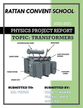
8. CONSTRUCTION
A transformer consists of primary and secondary coils
insulated from each other, wound on a soft iron core.
To minimize eddy current a laminated iron core is
used. The a.c. input is applied across the primary coil.
The continuously varying current in the primary coil
produces a varying magnetic flux in the primary coil,
which in turn produces a varying magnetic flux in the
secondary. Hence, an induced emf is produced across
the secondary.
Let EP and ES be the induced emf in the primary and
secondary coils and NP and NS be the number of
turns in the primary and secondary coils respectively.
Since same flux links with the primary and secondary,
the emf induced per turn of the two coils must be the
same.
9. THEORY AND WORKING
The working of the transformer is explained below.
The transformer consists of two separate windings
placed over the laminated silicon steel core.
The winding to which AC supply is connected is called
primary winding and to which load is connected is
called secondary winding as shown in the fig. below.
It works on the alternating current only because an
alternating flux is required for mutual induction
between the two windings.
10. When the AC supply is given to the primary winding
with a voltage of v1, an alternating flux sets up in
the core of the transformer, which links with the
secondary winding and as a result of it, an emf is
induced in it called Mutually induced emf. The
direction of this induced emf is opposite to the
applied voltage v1, this is because of Lenz’s law.
Physically, there is no electrical connection between
the two windings, but they are magnetically
connected. Therefore, the electrical power is
transferred from the primary circuit to the secondary
circuit through mutual inductance. The induced emf in
the primary and secondary coil depends upon the
rate of change of flux linkage i.e., (Nd/dt).
11. d/dt is the change of flux and is same for both the
primary and secondary coils. The induced emf in the
primary winding is directly proportional to the
number of turns of primary coil. Similarly, induced
emf in the secondary coil directly proportional to the
number of turns in the secondary coil.
TRANSFORMER ON DC SUPPLY: -
As discussed above, the transformer works on AC
supply, and it can not work on DC supply. If the
rated dc voltage is applied across the primary coil, a
constant magnitude flux will set up in the core of the
transformer and hence there will be no self-induced
emf generation, and as for the linkage of flux with
the secondary coil there must be alternating flux not
a constant flux.
12. According to OHM’s Law: -
PRIMARY CURRENT = DC APPLIED VOLTAGE
RESISTANCE OF PRIMARY COIL
The resistance of the primary coil is very low, and the
primary current is high. So, this current is much higher
than the rated full loaded primary coil current.
Hence, as a result, the amount of heat produced will
be greater and therefore eddy current loss will be
more. Because of this, the insulations of the primary
coil will get burnt, and the transformer will be
damaged.
Turn ratio: -
It is defined as the ratio of no of turns in the primary
coil to that of the secondary coil.
Turn ratio = N1/N2
If N2>N1 the transformer is called step up
transformer.
If N2<N1 the transformer is called step down
transformer.
13. Transformer Efficiency
The Efficiency of the transformer is defined as the
ratio of useful output power to the input power. The
input and output power are measured in the same
unit. Its unit is either in Watts (W) or
KW. Transformer efficiency is denoted by Ƞ.
14. Energy losses in a transformer
Even though transformers are very efficient machines,
they do result in small energy losses due to four main
causes:
The resistance of windings – The low resistance
copper cable used for the windings remains resistant
and thus leads to heat loss. In order to minimize this
loss thick wires with considerably low resistance are
used.
Leakage of flux – If the core design is not good then
the flux produced by the primary coil may not all be
connected to the secondary coil. This can be reduced
by considering the core of shell type.
Eddy currents loss – The varying magnetic field not
only induces secondary coil currents but also iron core
currents themselves. In the iron core, these currents
flow in small circles and are termed as eddy currents.
The eddy current loss can be minimized by
considering the laminated core.
Hysteresis – This is because of the repeated iron
core magnetization and demagnetization induced by
the alternating input current. By using alloys such as
silicon steel, this can be reduced.
15. USES OF TRANSFORMER
Power Transformers: These kinds of transformers
are used for high voltage power transfer
applications (more than 33 KV). They are usually
bigger in size and can occupy larger space.
Distribution Transformers: These types of
transformers are used to distribute the generated
power to distant locations. It is used for distributing
electricity at low voltage that is less than 33 KV in
industry or 220-440 V for household purposes.
Measurement Transformers: This kind of uses of
transformer helps in measuring voltage, current, and
power, etc.
According to the place of use, transformers are
classified into:
Indoor Transformers: These are covered with roofs
and shelters just like the industry types.
Outdoor Transformers: These are mainly kept
outside and are used as distribution type
transformers.