SlideShare uma empresa Scribd logo
1 de 4
Baixar para ler offline
International Journal For Technological Research In Engineering
Volume 3, Issue 6, February-2016 ISSN (Online): 2347 - 4718
www.ijtre.com Copyright 2015.All rights reserved. 1225
ANALYSIS OF SPUR GEAR CUTTING USING MILLING
MACHINE
Sagar1
, Mr. Neeraj Kumar2
, Mr. Jagbir Sharma3
1
Student of M.E, 2
Assistant Professor, 3
Workshop in charge
Mechanical Dept., Panchkula Engineering College, Haryana.
ABSTRACT: Spur gears are the simplest type of the gear.
Spur gears have teeth parallel to the axis of the wheel. Spur
gears are the most commonly used for the transmission of
power. The most common method of cutting the spur gears
on milling machine is by form cutting. This is done by
taking a blank gear and rotating a cutter, with the desired
tooth pattern, around its periphery. This ensures that the
gear will fit when the operation is finished. While cutting
the spur gears using the milling machine, the analysis of
spur gear is very important. While analysis various
parameter like pressure angle, cutting speed, feed rate,
production time, tooth form, size of the teeth, pitch circle
diameter, depth of cut and outside diameter. All the aspects
are being calculated which is important while making the
spur gears. Spur gears are cutting on milling machine
utilized the various tooth cutters. The no of tooth cutters
can be determined by the tooth count of the gear to be cut
and also analysis the stress concentration in the spur gear
while cutting.
Keywords: Spur gear, milling machine, cutting tool, cutting
speed
I. INTRODUCTION
Gears are used for a wide range of industrial application.
Gears used in aviation industries, textile looms, automobile,
industrial machine, geared motors, agricultural machinery
etc. To meet the service conditions the geared should have
robust construction, reliable performance, high efficiency,
economy and long life. The gear should be fatigue free and
free from all stresses to avoid their failures. The gears should
be free from noise, chatter and should ensure high load
varying capacity at constant velocity ratio. Spur gears are the
mostly used in all type of gear. It is used for the transmitting
of power between two parallel shafts. In this type of gear, the
teeth cut on the cylindrical face are parallel to the axis of the
gear. In milling, a multi-toothed cutter, rotating at a fixed
position on the machine, shapes the work as it is traversed
across the cutter. The work is firmly secured on the machine
table which can be adjusted to set the depth of cut and can be
moves directions in the horizontal plane. In some machines, a
vertical transverse also is possible manufacture of metallic
components using conventional machine tools, cutter tool
wear, its effects on surface finish, and cutter tool failure
provide major limitations to the achievement of economic
production.Form-milling the tooth of involute spur gear
involves specification of the cutting speed for the work piece
material and feed rate of the milling cutter. The speed and
feed rate selection for such cutting has a strong link with the
completion period of the machining exercise, which
indirectly also determines the cost of producing the gears. In
cutting of the gear, most important is that machinability.
Machinability is defined that to cut the material how easily
on a machine to get the desired shape with respect to tooling.
Figure 1 Spur Gear
Form milling is the process of machining special profile
composed of curved and straight lines. It is done with milling
cutter shaped to the profile to be cut.
II. METHOD FOR GEAR CUTTING
Gear cutting on a milling machine, the gear blank is mounted
on a mandrel which is supported between the center of the
dividing head and one more center at the other end. one tooth
space is cut by the milling cutter and a dividing head
/indexing head is used to index the job to the next required
tooth space. The cutter is chosen according to the module (or
DP) and number of teeth of the gear to the cut. This cutter is
mounted on the milling arbor. Before the gear can be cut, it
is necessary to have the cutter centered accurately relative to
the gear holding mandrel. One way is to adjust the machine
table vertically and horizontally until one corner of the cutter
just touches the mandrel on one side. Both the dials are then
set to zero. The table is then adjusted for the cutter to just
touch on the other side of the mandrel with vertical dial
showing zero. The reading of the horizontal feed screw is
read. This reading divided by two gives the central position
of the mandrel relative to the cutter. When the table is set
centrally in this manner it should be locked in that position.
The table is then fed vertically so that the blank just touches
the cutter. The vertical dial is then set to zero. This is
required to give the depth of cut on the job.With these
settings the machine can be started and traversed along the
axis of the job to cut the tooth over the whole width of the
gear. Depth is increased slowly until it reaches the full depth
International Journal For Technological Research In Engineering
Volume 3, Issue 6, February-2016 ISSN (Online): 2347 - 4718
www.ijtre.com Copyright 2015.All rights reserved. 1226
of the tooth. With the depth setting the backlash of the gear
can be controlled suitably and gear can be manufactured.
Figure 2: Milling Machine
III. PROCEDURE OF GEAR CUTTING
While cutting the gear on a milling machine, it is important
to know how to make the spur gear. One of the most common
ways of making spur gears is by using a dividing head on a
milling machine. The dividing head makes it possible to cut a
gear with almost any number of teeth. It is possible to use
either a horizontal milling machine or a vertical milling
machine. Work piece to be held in dividing head.
A. DIVIDING HEAD
The dividing head is essentially a horizontal shaft with a
worm wheel on it that can be driven round by means of a
worm. The shaft has various means of holding a work piece.
This may seem very similar to a rotary table. It is different in
that there is no table to mount the work piece on. It is
possible to mount a center in the shaft or mount a chuck onto
it. Usually dividing heads are supplied with a tailstock. This
is essential when using a center with the dividing head. It can
also be very useful for supporting the workpiece when using
the chuck. On all dividing heads the worm is turned by
means of a handle. Each turn of the handle can be divided by
means of a dividing plate that contains a number of rings
each with a different number of holes in it. The handle has a
pin that can be moved to fit the holes in any one of the rings
of holes. Dividing heads are designed to divide the circle.
They are not designed to turn by so many degrees though this
can be done.
Figure 3: Dividing Head
B. Indexing Plate:
Dividing plate is the most important part of the dividing
head. The major role of the dividing plate is to key the
dividing circle. The plate contains no of rings of holes. This
means that one turn of the handle can be divided into the
number of holes in the particular ring. Dividing plate having
no of holes on the half of plate drilled on one side and other
side to be drilled.The dividing plate is fitted properly all of
the “zero” holes will be in line and will be vertically above
the shaft of the handle. Usually, next to each of the zero
holes, is stamped the number of holes in the ring
Figure 4: Indexing Plate
C. Holding the work piece:
Work piece can be held in a chuck using with the help of
dividing head. Whereas on a lathe if a chuck holds the
workpiece slightly off center it is often still possible to turn
all the required surfaces so they are concentric to each other.
This is not relevant when milling. If the workpiece has to be
aligned accurately then it either has to be held between
centers or centered accurately using a four-jaw chuck. Most
home machinists do not have horizontal milling machines
but have a vertical one. In this case the gear cutter is held on
a stub arbor held in the vertical spindle’s socket. In this case,
the cutter cuts into the workpiece in the middle of the front
side. The cutters for gear cutting are designed for use on a
horizontal arbor. If a vertical milling machine is being used
then the same cutter is used but it is mounted on a stub arbor.
This is then fitted to the vertical head. High speed cutter cut
the material and makes the teeth on the material and soluble
oil use for the Cooling of cutter and removes the dissipated
heat.
IV. CUTTER OF CUTTING SPUR GEAR
A cutter that was made for a tooth size would make any gear
with that size tooth. But, unfortunately, for any given size of
tooth, pressure angle etc. the shape of the tooth will vary
depending upon the number of teeth on the gear being made.
This means that to be able to cut a gear with any number of
teeth but for a given size of tooth a set of eight cutters is
required. In order to cope with this it is necessary to have a
cutter for each of a range of teeth numbers.
International Journal For Technological Research In Engineering
Volume 3, Issue 6, February-2016 ISSN (Online): 2347 - 4718
www.ijtre.com Copyright 2015.All rights reserved. 1227
Figure 5: High Speed Cutter
V. SPUR GEAR PARAMETER
There are still a few key features of gear we need and have to
be defined. For gear of size having 28 teeth to mesh properly
with the other gear. There are several conditions that must be
fulfilled:
A. No of Teeth
The number of teeth is important since this determines the
gearing obtained with other gear of this or other numbers of
teeth. Spur gear made on a milling machine having 28 teeth
in proper manner so that they can mesh withanother gear
without rubbing and do not create wear and friction and work
properly.
B. Pitch Circle Diameter
Though a gear has an outside diameter this is not as
important as the pitch circle diameter. This is the distance
between the two centers of two identical gears meshed
together. It is roughly the distance from the middle of a tooth
on one side of the gear to the middle of a tooth on the other
side.
C. Outside Diameter
The gear will have an outside diameter. This is the size the
blank has to be turned down to. Since gears are usually
defined by their tooth size and the number of teeth these set
the outside diameter.
Outside diameter = (no of teeth +2)/ module
D. Depth of Cut
The depth the cutter needs to cut is always marked upon the
gear cutter. It includes an allowance of 10% at the bottom of
the cut so the top of one lot of teeth will not clash with the
bottoms of the other gear
E. Pressure Angle
Where two gears touch each other the angle relative to a
normal on the pitch circle diameter to the tooth face at this
point can vary. In the past the fashion was for a pressure
angle of 14.5º. The current fashion is for 20º. For special
applications this can be even higher.
VI. MATHEMATICAL FORMULAE’S AND TABLE
 PCD = module * no of teeth
 Diametric Pitch = no of teeth / pitch circle diameter
 Circular pitch = (pi * pitch circle diameter) / no of
teeth.
 Outside diameter =(no of teeth +2)/ module
 Cutting Speed= (pi * Diameter * spindle speed) /
1000.
 Feed = spindle speed * feed per tooth * no of flutes
 Indexing Movement = 40 / no of teeth
Observation Reading
No of teeth 28 teeth
Module 2.5
Pitch circle diameter 70mm
Pressure angle 20 deg.
Material Mild Steel
Outside Diameter 75 mm
Indexing Movement 1.428
Working depth mm
circular Pitch 0.7837mm
VII. CONCLUSION
In present work steps involved in manufacturing engineering
of gear teeth have been explained using steps like alignment
of mandrel on which work piece or job to be held, Work
piece size, cutter, center mark on job and teeth profile
generation. According to the manufacturing of the spur gear
various kind of parameter have been calculated. These
parameter help the fresher and new student how to cut the
spur gear on the milling machine using form cutting
technique. Various doubts are being easily solved. In this
paper, analysis that time taken for cutting spur gear tooth
reduces with increase in the cutting speed and feed rate
respectively.
REFERENCES
[1] Khurmi. R. S and Gupta. J. B, a textbook of
machine design, 14th
edition, India: Eurasia
Publishing house limited, 2014.
[2] Oladejo, K.A. and Oriolovo, K.T.,” Analysis of
Gear Milling at various speed, time and feed rate”,
Nigerian Journal of technology (NIJOTECH),
vol.34, No.1, January 2015, pp.150-155.
[3] Kumar. A, Jain. P. K and Pathak. P. M.,” Study of
Tooth Wear on Spur Gear Performance Parameters
Using Reverse Engineering”, International
Conference on Production and Mechanical
Engineering (ICPME), Dec 2014,pp. 30-31, 2014
Bangkok, Thailand.
[4] Rech, J. and Moissan, A., “Surface Hardened
Steels”, International Journal Machine Tools and
Manufacture, vol. 43, Issues 5, pp. 543-550, 2007.
[5] Ozel. C,” Research of production times and cutting
of the spur gears by end mill in CNC milling
machine”, International Journal of Advanced
Manufacturing Technology 54(1):pp.203-213 ·
April 2011.
[6] Papaioannou.S.G,” Manufacture of High Precision
Spur Gears with End Milling Cutters”, The
American Society of Engineers, vol.10, pp-359-366,
1988.
International Journal For Technological Research In Engineering
Volume 3, Issue 6, February-2016 ISSN (Online): 2347 - 4718
www.ijtre.com Copyright 2015.All rights reserved. 1228
[7] Kumar. M. D,” Fabrication of multi milling
process”, international journal of research in
aeronautical and mechanical engineering”, Vol.2
Issue.2, February 2014, Pgs.: 105-111.
Sagar is pursuing Bachelor of Technology from Panchkula
Engineering College Barwala in the Department of
Mechanical Engineering. His research interest includes
designing, manufacturing and production. It is my first
research paper that I published in international level.
Student of Mechanical Engineering
Mr. Neeraj Kumar is working as assistant professor in the
Mechanical Department at Panchkula Engineering College
Haryana.Currently, he is also the Head of the department. He
obtained his M.Tech in the area of thermal engineering from
National Institute of technology Kurukshetra.He has
published several research papers and articles in various
reputed national and international journals and attend various
conferences.
HOD of Mechanical Department
Mr. Jagbir Sharma is working as a workshop in charge in the
Mechanical Department a Panchkula Engineering College
Haryana. He had done ITI form Ambala. He had worked in
various industries having 22 years experience in mechanical
department and also in teaching.
Workshop In charge

Mais conteúdo relacionado

Mais procurados

Horizontal Spindle and Reciprocating Table
Horizontal Spindle and Reciprocating TableHorizontal Spindle and Reciprocating Table
Horizontal Spindle and Reciprocating TableSiddiqui Mohsin
 
CAM AND FOLLOWER
CAM AND FOLLOWERCAM AND FOLLOWER
CAM AND FOLLOWERAJAY SAVITA
 
1 b. Machine design - Prefered numbers, asthetic and ergonomic design
1 b. Machine design - Prefered numbers, asthetic and ergonomic design1 b. Machine design - Prefered numbers, asthetic and ergonomic design
1 b. Machine design - Prefered numbers, asthetic and ergonomic designDr.R. SELVAM
 
LATHE: LATHE PARTS AND SPECIFICATIONS OF LATHE MACHINE BY POLAYYA CHINTADA
LATHE: LATHE PARTS AND SPECIFICATIONS OF LATHE MACHINE BY POLAYYA CHINTADA LATHE: LATHE PARTS AND SPECIFICATIONS OF LATHE MACHINE BY POLAYYA CHINTADA
LATHE: LATHE PARTS AND SPECIFICATIONS OF LATHE MACHINE BY POLAYYA CHINTADA POLAYYA CHINTADA
 
Multi spindle drilling machine project report
Multi spindle drilling machine project reportMulti spindle drilling machine project report
Multi spindle drilling machine project reportDeepak kango
 
MT-II UNIT II TURNING
MT-II UNIT II TURNING MT-II UNIT II TURNING
MT-II UNIT II TURNING Karthik R
 
Part 1: Shaper Planer & Slotter machine
Part 1: Shaper Planer & Slotter machinePart 1: Shaper Planer & Slotter machine
Part 1: Shaper Planer & Slotter machineSBM Polytechnic
 
Fabrication of abrasive belt grinder saravanan
Fabrication of abrasive belt grinder   saravananFabrication of abrasive belt grinder   saravanan
Fabrication of abrasive belt grinder saravanandinnusara
 
Slotting machine
Slotting machineSlotting machine
Slotting machinenmahi96
 
10 gear manufacturing process
10  gear manufacturing process10  gear manufacturing process
10 gear manufacturing processM Siva Kumar
 
Shaper machine tool
Shaper machine toolShaper machine tool
Shaper machine toolManish Singh
 

Mais procurados (20)

Gear drives
Gear drivesGear drives
Gear drives
 
Horizontal Spindle and Reciprocating Table
Horizontal Spindle and Reciprocating TableHorizontal Spindle and Reciprocating Table
Horizontal Spindle and Reciprocating Table
 
broaching
broachingbroaching
broaching
 
CAM AND FOLLOWER
CAM AND FOLLOWERCAM AND FOLLOWER
CAM AND FOLLOWER
 
Types of grinding machines
Types of grinding machines Types of grinding machines
Types of grinding machines
 
1 b. Machine design - Prefered numbers, asthetic and ergonomic design
1 b. Machine design - Prefered numbers, asthetic and ergonomic design1 b. Machine design - Prefered numbers, asthetic and ergonomic design
1 b. Machine design - Prefered numbers, asthetic and ergonomic design
 
Lathe operations
Lathe operationsLathe operations
Lathe operations
 
LATHE: LATHE PARTS AND SPECIFICATIONS OF LATHE MACHINE BY POLAYYA CHINTADA
LATHE: LATHE PARTS AND SPECIFICATIONS OF LATHE MACHINE BY POLAYYA CHINTADA LATHE: LATHE PARTS AND SPECIFICATIONS OF LATHE MACHINE BY POLAYYA CHINTADA
LATHE: LATHE PARTS AND SPECIFICATIONS OF LATHE MACHINE BY POLAYYA CHINTADA
 
Types of Gears
Types of GearsTypes of Gears
Types of Gears
 
Multi spindle drilling machine project report
Multi spindle drilling machine project reportMulti spindle drilling machine project report
Multi spindle drilling machine project report
 
spur gear design
spur gear designspur gear design
spur gear design
 
MT-II UNIT II TURNING
MT-II UNIT II TURNING MT-II UNIT II TURNING
MT-II UNIT II TURNING
 
Part 1: Shaper Planer & Slotter machine
Part 1: Shaper Planer & Slotter machinePart 1: Shaper Planer & Slotter machine
Part 1: Shaper Planer & Slotter machine
 
Fabrication of abrasive belt grinder saravanan
Fabrication of abrasive belt grinder   saravananFabrication of abrasive belt grinder   saravanan
Fabrication of abrasive belt grinder saravanan
 
Cylindrical grinding
Cylindrical grindingCylindrical grinding
Cylindrical grinding
 
Slotting machine
Slotting machineSlotting machine
Slotting machine
 
10 gear manufacturing process
10  gear manufacturing process10  gear manufacturing process
10 gear manufacturing process
 
Ch 8 grinding machines
Ch 8 grinding machines  Ch 8 grinding machines
Ch 8 grinding machines
 
Shaper machine tool
Shaper machine toolShaper machine tool
Shaper machine tool
 
Thread cutting
Thread cuttingThread cutting
Thread cutting
 

Semelhante a 5. analysis of spur gear cutting using milling

Gear manufacturing methods
Gear manufacturing methodsGear manufacturing methods
Gear manufacturing methodsKaushal Patel
 
Jigs & fixture turning
Jigs & fixture turningJigs & fixture turning
Jigs & fixture turningengdida
 
Workshop Report.pdf
Workshop Report.pdfWorkshop Report.pdf
Workshop Report.pdfHogr kamal
 
MILLING PRESENTATION.pdf
MILLING PRESENTATION.pdfMILLING PRESENTATION.pdf
MILLING PRESENTATION.pdfSadishPuri
 
Gear manufacturing process
Gear manufacturing processGear manufacturing process
Gear manufacturing processKANNANS94
 
Welcome to International Journal of Engineering Research and Development (IJERD)
Welcome to International Journal of Engineering Research and Development (IJERD)Welcome to International Journal of Engineering Research and Development (IJERD)
Welcome to International Journal of Engineering Research and Development (IJERD)IJERD Editor
 
UNIT 3 Machine tools and 3D Printing.pptx
UNIT 3 Machine tools and 3D Printing.pptxUNIT 3 Machine tools and 3D Printing.pptx
UNIT 3 Machine tools and 3D Printing.pptxmyselfnoobcoder
 
Milling and GearCutting.
Milling and GearCutting.Milling and GearCutting.
Milling and GearCutting.pranaydisale
 
Jigs & fixture turning
Jigs & fixture turningJigs & fixture turning
Jigs & fixture turningengdida
 
Mt 2 me8462- lab manual
Mt 2 me8462- lab manualMt 2 me8462- lab manual
Mt 2 me8462- lab manualprabhukala
 
mt lab-1 updated.docx
mt lab-1 updated.docxmt lab-1 updated.docx
mt lab-1 updated.docxARUNP361801
 
mt lab-1 updated (1).pdf
mt lab-1 updated (1).pdfmt lab-1 updated (1).pdf
mt lab-1 updated (1).pdfARUNP361801
 
Different flanking devices and attachment
Different flanking devices and attachmentDifferent flanking devices and attachment
Different flanking devices and attachmentAlbert Candor
 

Semelhante a 5. analysis of spur gear cutting using milling (20)

Gear manufacturing methods
Gear manufacturing methodsGear manufacturing methods
Gear manufacturing methods
 
Band sawing machine
Band sawing machineBand sawing machine
Band sawing machine
 
Jigs & fixture turning
Jigs & fixture turningJigs & fixture turning
Jigs & fixture turning
 
Workshop Report.pdf
Workshop Report.pdfWorkshop Report.pdf
Workshop Report.pdf
 
MILLING PRESENTATION.pdf
MILLING PRESENTATION.pdfMILLING PRESENTATION.pdf
MILLING PRESENTATION.pdf
 
Gear manufacturing process
Gear manufacturing processGear manufacturing process
Gear manufacturing process
 
Milling
MillingMilling
Milling
 
Miling machine
Miling machineMiling machine
Miling machine
 
Welcome to International Journal of Engineering Research and Development (IJERD)
Welcome to International Journal of Engineering Research and Development (IJERD)Welcome to International Journal of Engineering Research and Development (IJERD)
Welcome to International Journal of Engineering Research and Development (IJERD)
 
05 gears part 2 (1) (1) (1)
05 gears part 2 (1) (1) (1)05 gears part 2 (1) (1) (1)
05 gears part 2 (1) (1) (1)
 
machine tool & casting.pdf
machine tool & casting.pdfmachine tool & casting.pdf
machine tool & casting.pdf
 
UNIT 3 Machine tools and 3D Printing.pptx
UNIT 3 Machine tools and 3D Printing.pptxUNIT 3 Machine tools and 3D Printing.pptx
UNIT 3 Machine tools and 3D Printing.pptx
 
Milling and GearCutting.
Milling and GearCutting.Milling and GearCutting.
Milling and GearCutting.
 
Pp mills
Pp millsPp mills
Pp mills
 
Jigs & fixture turning
Jigs & fixture turningJigs & fixture turning
Jigs & fixture turning
 
Mt 2 me8462- lab manual
Mt 2 me8462- lab manualMt 2 me8462- lab manual
Mt 2 me8462- lab manual
 
mt lab-1 updated.docx
mt lab-1 updated.docxmt lab-1 updated.docx
mt lab-1 updated.docx
 
mt lab-1 updated (1).pdf
mt lab-1 updated (1).pdfmt lab-1 updated (1).pdf
mt lab-1 updated (1).pdf
 
MP-II-UNIT-5 milling.pptx
MP-II-UNIT-5 milling.pptxMP-II-UNIT-5 milling.pptx
MP-II-UNIT-5 milling.pptx
 
Different flanking devices and attachment
Different flanking devices and attachmentDifferent flanking devices and attachment
Different flanking devices and attachment
 

Mais de NEERAJKUMAR1898

performance study of electrochemical machining on metal matrix composite
performance study of electrochemical machining on metal matrix compositeperformance study of electrochemical machining on metal matrix composite
performance study of electrochemical machining on metal matrix compositeNEERAJKUMAR1898
 
a review performance study of electrochemical machining on metal
a review performance study of electrochemical machining on metala review performance study of electrochemical machining on metal
a review performance study of electrochemical machining on metalNEERAJKUMAR1898
 
17. a review on electrical, thermal and wear behaviour of al6061 ag composite
17. a review on electrical, thermal and wear behaviour of al6061 ag composite17. a review on electrical, thermal and wear behaviour of al6061 ag composite
17. a review on electrical, thermal and wear behaviour of al6061 ag compositeNEERAJKUMAR1898
 
16. experimental investigation on electrical, thermal and wear behaviour of a...
16. experimental investigation on electrical, thermal and wear behaviour of a...16. experimental investigation on electrical, thermal and wear behaviour of a...
16. experimental investigation on electrical, thermal and wear behaviour of a...NEERAJKUMAR1898
 
15. experimental investigation of heat transfer characteristics of
15. experimental investigation of heat transfer characteristics of15. experimental investigation of heat transfer characteristics of
15. experimental investigation of heat transfer characteristics ofNEERAJKUMAR1898
 
14. a review cohesive zone modeling of laminated composite beam
14. a review cohesive zone modeling of laminated composite beam14. a review cohesive zone modeling of laminated composite beam
14. a review cohesive zone modeling of laminated composite beamNEERAJKUMAR1898
 
cohesive zone modeling of laminated composite beam under mixed mode
cohesive zone modeling of laminated composite beam under mixed modecohesive zone modeling of laminated composite beam under mixed mode
cohesive zone modeling of laminated composite beam under mixed modeNEERAJKUMAR1898
 
experimental investigation of gas metal arc welding (gmaw) on 2.25
 experimental investigation of gas metal arc welding (gmaw) on 2.25 experimental investigation of gas metal arc welding (gmaw) on 2.25
experimental investigation of gas metal arc welding (gmaw) on 2.25NEERAJKUMAR1898
 
a survey on gas metal arc welding (gmaw) review
a survey on gas metal arc welding (gmaw) reviewa survey on gas metal arc welding (gmaw) review
a survey on gas metal arc welding (gmaw) reviewNEERAJKUMAR1898
 
a survey on submerged arc welding (saw) review
a survey on submerged arc welding (saw) reviewa survey on submerged arc welding (saw) review
a survey on submerged arc welding (saw) reviewNEERAJKUMAR1898
 
experimental investigation of submerged arc welding on high strength low allo...
experimental investigation of submerged arc welding on high strength low allo...experimental investigation of submerged arc welding on high strength low allo...
experimental investigation of submerged arc welding on high strength low allo...NEERAJKUMAR1898
 
experimental analysis on francis turbine & to find out the power
experimental analysis on francis turbine & to find out the powerexperimental analysis on francis turbine & to find out the power
experimental analysis on francis turbine & to find out the powerNEERAJKUMAR1898
 
7. iso implementation & survey for automobile industry
7. iso implementation & survey for automobile industry7. iso implementation & survey for automobile industry
7. iso implementation & survey for automobile industryNEERAJKUMAR1898
 
6. iso implementation a case study for an indian automobile industry
6. iso implementation a case study for an indian automobile industry6. iso implementation a case study for an indian automobile industry
6. iso implementation a case study for an indian automobile industryNEERAJKUMAR1898
 
3. analysis the effects of different types of tool on metal
3. analysis the effects of different types of tool on metal3. analysis the effects of different types of tool on metal
3. analysis the effects of different types of tool on metalNEERAJKUMAR1898
 
1. biogas as a alternate source of energy and creating awareness among rural ...
1. biogas as a alternate source of energy and creating awareness among rural ...1. biogas as a alternate source of energy and creating awareness among rural ...
1. biogas as a alternate source of energy and creating awareness among rural ...NEERAJKUMAR1898
 
ALUMINIUM METAL MATRIX COMPOSITE BY STIR CASTING METHODS
ALUMINIUM METAL MATRIX COMPOSITE BY STIR CASTING METHODSALUMINIUM METAL MATRIX COMPOSITE BY STIR CASTING METHODS
ALUMINIUM METAL MATRIX COMPOSITE BY STIR CASTING METHODSNEERAJKUMAR1898
 

Mais de NEERAJKUMAR1898 (17)

performance study of electrochemical machining on metal matrix composite
performance study of electrochemical machining on metal matrix compositeperformance study of electrochemical machining on metal matrix composite
performance study of electrochemical machining on metal matrix composite
 
a review performance study of electrochemical machining on metal
a review performance study of electrochemical machining on metala review performance study of electrochemical machining on metal
a review performance study of electrochemical machining on metal
 
17. a review on electrical, thermal and wear behaviour of al6061 ag composite
17. a review on electrical, thermal and wear behaviour of al6061 ag composite17. a review on electrical, thermal and wear behaviour of al6061 ag composite
17. a review on electrical, thermal and wear behaviour of al6061 ag composite
 
16. experimental investigation on electrical, thermal and wear behaviour of a...
16. experimental investigation on electrical, thermal and wear behaviour of a...16. experimental investigation on electrical, thermal and wear behaviour of a...
16. experimental investigation on electrical, thermal and wear behaviour of a...
 
15. experimental investigation of heat transfer characteristics of
15. experimental investigation of heat transfer characteristics of15. experimental investigation of heat transfer characteristics of
15. experimental investigation of heat transfer characteristics of
 
14. a review cohesive zone modeling of laminated composite beam
14. a review cohesive zone modeling of laminated composite beam14. a review cohesive zone modeling of laminated composite beam
14. a review cohesive zone modeling of laminated composite beam
 
cohesive zone modeling of laminated composite beam under mixed mode
cohesive zone modeling of laminated composite beam under mixed modecohesive zone modeling of laminated composite beam under mixed mode
cohesive zone modeling of laminated composite beam under mixed mode
 
experimental investigation of gas metal arc welding (gmaw) on 2.25
 experimental investigation of gas metal arc welding (gmaw) on 2.25 experimental investigation of gas metal arc welding (gmaw) on 2.25
experimental investigation of gas metal arc welding (gmaw) on 2.25
 
a survey on gas metal arc welding (gmaw) review
a survey on gas metal arc welding (gmaw) reviewa survey on gas metal arc welding (gmaw) review
a survey on gas metal arc welding (gmaw) review
 
a survey on submerged arc welding (saw) review
a survey on submerged arc welding (saw) reviewa survey on submerged arc welding (saw) review
a survey on submerged arc welding (saw) review
 
experimental investigation of submerged arc welding on high strength low allo...
experimental investigation of submerged arc welding on high strength low allo...experimental investigation of submerged arc welding on high strength low allo...
experimental investigation of submerged arc welding on high strength low allo...
 
experimental analysis on francis turbine & to find out the power
experimental analysis on francis turbine & to find out the powerexperimental analysis on francis turbine & to find out the power
experimental analysis on francis turbine & to find out the power
 
7. iso implementation & survey for automobile industry
7. iso implementation & survey for automobile industry7. iso implementation & survey for automobile industry
7. iso implementation & survey for automobile industry
 
6. iso implementation a case study for an indian automobile industry
6. iso implementation a case study for an indian automobile industry6. iso implementation a case study for an indian automobile industry
6. iso implementation a case study for an indian automobile industry
 
3. analysis the effects of different types of tool on metal
3. analysis the effects of different types of tool on metal3. analysis the effects of different types of tool on metal
3. analysis the effects of different types of tool on metal
 
1. biogas as a alternate source of energy and creating awareness among rural ...
1. biogas as a alternate source of energy and creating awareness among rural ...1. biogas as a alternate source of energy and creating awareness among rural ...
1. biogas as a alternate source of energy and creating awareness among rural ...
 
ALUMINIUM METAL MATRIX COMPOSITE BY STIR CASTING METHODS
ALUMINIUM METAL MATRIX COMPOSITE BY STIR CASTING METHODSALUMINIUM METAL MATRIX COMPOSITE BY STIR CASTING METHODS
ALUMINIUM METAL MATRIX COMPOSITE BY STIR CASTING METHODS
 

Último

Introduction to Multiple Access Protocol.pptx
Introduction to Multiple Access Protocol.pptxIntroduction to Multiple Access Protocol.pptx
Introduction to Multiple Access Protocol.pptxupamatechverse
 
High Profile Call Girls Nagpur Isha Call 7001035870 Meet With Nagpur Escorts
High Profile Call Girls Nagpur Isha Call 7001035870 Meet With Nagpur EscortsHigh Profile Call Girls Nagpur Isha Call 7001035870 Meet With Nagpur Escorts
High Profile Call Girls Nagpur Isha Call 7001035870 Meet With Nagpur Escortsranjana rawat
 
AKTU Computer Networks notes --- Unit 3.pdf
AKTU Computer Networks notes ---  Unit 3.pdfAKTU Computer Networks notes ---  Unit 3.pdf
AKTU Computer Networks notes --- Unit 3.pdfankushspencer015
 
Processing & Properties of Floor and Wall Tiles.pptx
Processing & Properties of Floor and Wall Tiles.pptxProcessing & Properties of Floor and Wall Tiles.pptx
Processing & Properties of Floor and Wall Tiles.pptxpranjaldaimarysona
 
CCS335 _ Neural Networks and Deep Learning Laboratory_Lab Complete Record
CCS335 _ Neural Networks and Deep Learning Laboratory_Lab Complete RecordCCS335 _ Neural Networks and Deep Learning Laboratory_Lab Complete Record
CCS335 _ Neural Networks and Deep Learning Laboratory_Lab Complete RecordAsst.prof M.Gokilavani
 
Call Girls Service Nagpur Tanvi Call 7001035870 Meet With Nagpur Escorts
Call Girls Service Nagpur Tanvi Call 7001035870 Meet With Nagpur EscortsCall Girls Service Nagpur Tanvi Call 7001035870 Meet With Nagpur Escorts
Call Girls Service Nagpur Tanvi Call 7001035870 Meet With Nagpur EscortsCall Girls in Nagpur High Profile
 
Booking open Available Pune Call Girls Koregaon Park 6297143586 Call Hot Ind...
Booking open Available Pune Call Girls Koregaon Park  6297143586 Call Hot Ind...Booking open Available Pune Call Girls Koregaon Park  6297143586 Call Hot Ind...
Booking open Available Pune Call Girls Koregaon Park 6297143586 Call Hot Ind...Call Girls in Nagpur High Profile
 
MANUFACTURING PROCESS-II UNIT-5 NC MACHINE TOOLS
MANUFACTURING PROCESS-II UNIT-5 NC MACHINE TOOLSMANUFACTURING PROCESS-II UNIT-5 NC MACHINE TOOLS
MANUFACTURING PROCESS-II UNIT-5 NC MACHINE TOOLSSIVASHANKAR N
 
College Call Girls Nashik Nehal 7001305949 Independent Escort Service Nashik
College Call Girls Nashik Nehal 7001305949 Independent Escort Service NashikCollege Call Girls Nashik Nehal 7001305949 Independent Escort Service Nashik
College Call Girls Nashik Nehal 7001305949 Independent Escort Service NashikCall Girls in Nagpur High Profile
 
UNIT-V FMM.HYDRAULIC TURBINE - Construction and working
UNIT-V FMM.HYDRAULIC TURBINE - Construction and workingUNIT-V FMM.HYDRAULIC TURBINE - Construction and working
UNIT-V FMM.HYDRAULIC TURBINE - Construction and workingrknatarajan
 
Russian Call Girls in Nagpur Grishma Call 7001035870 Meet With Nagpur Escorts
Russian Call Girls in Nagpur Grishma Call 7001035870 Meet With Nagpur EscortsRussian Call Girls in Nagpur Grishma Call 7001035870 Meet With Nagpur Escorts
Russian Call Girls in Nagpur Grishma Call 7001035870 Meet With Nagpur EscortsCall Girls in Nagpur High Profile
 
Extrusion Processes and Their Limitations
Extrusion Processes and Their LimitationsExtrusion Processes and Their Limitations
Extrusion Processes and Their Limitations120cr0395
 
VIP Call Girls Ankleshwar 7001035870 Whatsapp Number, 24/07 Booking
VIP Call Girls Ankleshwar 7001035870 Whatsapp Number, 24/07 BookingVIP Call Girls Ankleshwar 7001035870 Whatsapp Number, 24/07 Booking
VIP Call Girls Ankleshwar 7001035870 Whatsapp Number, 24/07 Bookingdharasingh5698
 
Top Rated Pune Call Girls Budhwar Peth ⟟ 6297143586 ⟟ Call Me For Genuine Se...
Top Rated  Pune Call Girls Budhwar Peth ⟟ 6297143586 ⟟ Call Me For Genuine Se...Top Rated  Pune Call Girls Budhwar Peth ⟟ 6297143586 ⟟ Call Me For Genuine Se...
Top Rated Pune Call Girls Budhwar Peth ⟟ 6297143586 ⟟ Call Me For Genuine Se...Call Girls in Nagpur High Profile
 
MANUFACTURING PROCESS-II UNIT-1 THEORY OF METAL CUTTING
MANUFACTURING PROCESS-II UNIT-1 THEORY OF METAL CUTTINGMANUFACTURING PROCESS-II UNIT-1 THEORY OF METAL CUTTING
MANUFACTURING PROCESS-II UNIT-1 THEORY OF METAL CUTTINGSIVASHANKAR N
 
MANUFACTURING PROCESS-II UNIT-2 LATHE MACHINE
MANUFACTURING PROCESS-II UNIT-2 LATHE MACHINEMANUFACTURING PROCESS-II UNIT-2 LATHE MACHINE
MANUFACTURING PROCESS-II UNIT-2 LATHE MACHINESIVASHANKAR N
 
Structural Analysis and Design of Foundations: A Comprehensive Handbook for S...
Structural Analysis and Design of Foundations: A Comprehensive Handbook for S...Structural Analysis and Design of Foundations: A Comprehensive Handbook for S...
Structural Analysis and Design of Foundations: A Comprehensive Handbook for S...Dr.Costas Sachpazis
 
Call Girls Pimpri Chinchwad Call Me 7737669865 Budget Friendly No Advance Boo...
Call Girls Pimpri Chinchwad Call Me 7737669865 Budget Friendly No Advance Boo...Call Girls Pimpri Chinchwad Call Me 7737669865 Budget Friendly No Advance Boo...
Call Girls Pimpri Chinchwad Call Me 7737669865 Budget Friendly No Advance Boo...roncy bisnoi
 
The Most Attractive Pune Call Girls Manchar 8250192130 Will You Miss This Cha...
The Most Attractive Pune Call Girls Manchar 8250192130 Will You Miss This Cha...The Most Attractive Pune Call Girls Manchar 8250192130 Will You Miss This Cha...
The Most Attractive Pune Call Girls Manchar 8250192130 Will You Miss This Cha...ranjana rawat
 

Último (20)

Introduction to Multiple Access Protocol.pptx
Introduction to Multiple Access Protocol.pptxIntroduction to Multiple Access Protocol.pptx
Introduction to Multiple Access Protocol.pptx
 
High Profile Call Girls Nagpur Isha Call 7001035870 Meet With Nagpur Escorts
High Profile Call Girls Nagpur Isha Call 7001035870 Meet With Nagpur EscortsHigh Profile Call Girls Nagpur Isha Call 7001035870 Meet With Nagpur Escorts
High Profile Call Girls Nagpur Isha Call 7001035870 Meet With Nagpur Escorts
 
AKTU Computer Networks notes --- Unit 3.pdf
AKTU Computer Networks notes ---  Unit 3.pdfAKTU Computer Networks notes ---  Unit 3.pdf
AKTU Computer Networks notes --- Unit 3.pdf
 
Processing & Properties of Floor and Wall Tiles.pptx
Processing & Properties of Floor and Wall Tiles.pptxProcessing & Properties of Floor and Wall Tiles.pptx
Processing & Properties of Floor and Wall Tiles.pptx
 
CCS335 _ Neural Networks and Deep Learning Laboratory_Lab Complete Record
CCS335 _ Neural Networks and Deep Learning Laboratory_Lab Complete RecordCCS335 _ Neural Networks and Deep Learning Laboratory_Lab Complete Record
CCS335 _ Neural Networks and Deep Learning Laboratory_Lab Complete Record
 
Call Girls Service Nagpur Tanvi Call 7001035870 Meet With Nagpur Escorts
Call Girls Service Nagpur Tanvi Call 7001035870 Meet With Nagpur EscortsCall Girls Service Nagpur Tanvi Call 7001035870 Meet With Nagpur Escorts
Call Girls Service Nagpur Tanvi Call 7001035870 Meet With Nagpur Escorts
 
Booking open Available Pune Call Girls Koregaon Park 6297143586 Call Hot Ind...
Booking open Available Pune Call Girls Koregaon Park  6297143586 Call Hot Ind...Booking open Available Pune Call Girls Koregaon Park  6297143586 Call Hot Ind...
Booking open Available Pune Call Girls Koregaon Park 6297143586 Call Hot Ind...
 
MANUFACTURING PROCESS-II UNIT-5 NC MACHINE TOOLS
MANUFACTURING PROCESS-II UNIT-5 NC MACHINE TOOLSMANUFACTURING PROCESS-II UNIT-5 NC MACHINE TOOLS
MANUFACTURING PROCESS-II UNIT-5 NC MACHINE TOOLS
 
College Call Girls Nashik Nehal 7001305949 Independent Escort Service Nashik
College Call Girls Nashik Nehal 7001305949 Independent Escort Service NashikCollege Call Girls Nashik Nehal 7001305949 Independent Escort Service Nashik
College Call Girls Nashik Nehal 7001305949 Independent Escort Service Nashik
 
UNIT-V FMM.HYDRAULIC TURBINE - Construction and working
UNIT-V FMM.HYDRAULIC TURBINE - Construction and workingUNIT-V FMM.HYDRAULIC TURBINE - Construction and working
UNIT-V FMM.HYDRAULIC TURBINE - Construction and working
 
Russian Call Girls in Nagpur Grishma Call 7001035870 Meet With Nagpur Escorts
Russian Call Girls in Nagpur Grishma Call 7001035870 Meet With Nagpur EscortsRussian Call Girls in Nagpur Grishma Call 7001035870 Meet With Nagpur Escorts
Russian Call Girls in Nagpur Grishma Call 7001035870 Meet With Nagpur Escorts
 
Extrusion Processes and Their Limitations
Extrusion Processes and Their LimitationsExtrusion Processes and Their Limitations
Extrusion Processes and Their Limitations
 
VIP Call Girls Ankleshwar 7001035870 Whatsapp Number, 24/07 Booking
VIP Call Girls Ankleshwar 7001035870 Whatsapp Number, 24/07 BookingVIP Call Girls Ankleshwar 7001035870 Whatsapp Number, 24/07 Booking
VIP Call Girls Ankleshwar 7001035870 Whatsapp Number, 24/07 Booking
 
Top Rated Pune Call Girls Budhwar Peth ⟟ 6297143586 ⟟ Call Me For Genuine Se...
Top Rated  Pune Call Girls Budhwar Peth ⟟ 6297143586 ⟟ Call Me For Genuine Se...Top Rated  Pune Call Girls Budhwar Peth ⟟ 6297143586 ⟟ Call Me For Genuine Se...
Top Rated Pune Call Girls Budhwar Peth ⟟ 6297143586 ⟟ Call Me For Genuine Se...
 
Roadmap to Membership of RICS - Pathways and Routes
Roadmap to Membership of RICS - Pathways and RoutesRoadmap to Membership of RICS - Pathways and Routes
Roadmap to Membership of RICS - Pathways and Routes
 
MANUFACTURING PROCESS-II UNIT-1 THEORY OF METAL CUTTING
MANUFACTURING PROCESS-II UNIT-1 THEORY OF METAL CUTTINGMANUFACTURING PROCESS-II UNIT-1 THEORY OF METAL CUTTING
MANUFACTURING PROCESS-II UNIT-1 THEORY OF METAL CUTTING
 
MANUFACTURING PROCESS-II UNIT-2 LATHE MACHINE
MANUFACTURING PROCESS-II UNIT-2 LATHE MACHINEMANUFACTURING PROCESS-II UNIT-2 LATHE MACHINE
MANUFACTURING PROCESS-II UNIT-2 LATHE MACHINE
 
Structural Analysis and Design of Foundations: A Comprehensive Handbook for S...
Structural Analysis and Design of Foundations: A Comprehensive Handbook for S...Structural Analysis and Design of Foundations: A Comprehensive Handbook for S...
Structural Analysis and Design of Foundations: A Comprehensive Handbook for S...
 
Call Girls Pimpri Chinchwad Call Me 7737669865 Budget Friendly No Advance Boo...
Call Girls Pimpri Chinchwad Call Me 7737669865 Budget Friendly No Advance Boo...Call Girls Pimpri Chinchwad Call Me 7737669865 Budget Friendly No Advance Boo...
Call Girls Pimpri Chinchwad Call Me 7737669865 Budget Friendly No Advance Boo...
 
The Most Attractive Pune Call Girls Manchar 8250192130 Will You Miss This Cha...
The Most Attractive Pune Call Girls Manchar 8250192130 Will You Miss This Cha...The Most Attractive Pune Call Girls Manchar 8250192130 Will You Miss This Cha...
The Most Attractive Pune Call Girls Manchar 8250192130 Will You Miss This Cha...
 

5. analysis of spur gear cutting using milling

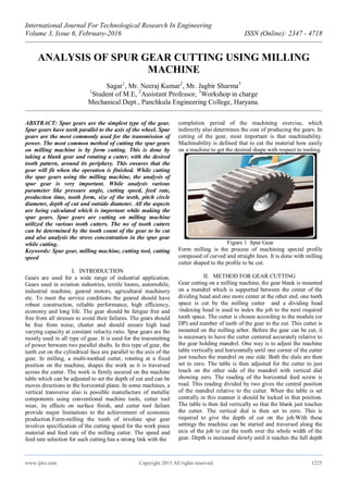
  • 1. International Journal For Technological Research In Engineering Volume 3, Issue 6, February-2016 ISSN (Online): 2347 - 4718 www.ijtre.com Copyright 2015.All rights reserved. 1225 ANALYSIS OF SPUR GEAR CUTTING USING MILLING MACHINE Sagar1 , Mr. Neeraj Kumar2 , Mr. Jagbir Sharma3 1 Student of M.E, 2 Assistant Professor, 3 Workshop in charge Mechanical Dept., Panchkula Engineering College, Haryana. ABSTRACT: Spur gears are the simplest type of the gear. Spur gears have teeth parallel to the axis of the wheel. Spur gears are the most commonly used for the transmission of power. The most common method of cutting the spur gears on milling machine is by form cutting. This is done by taking a blank gear and rotating a cutter, with the desired tooth pattern, around its periphery. This ensures that the gear will fit when the operation is finished. While cutting the spur gears using the milling machine, the analysis of spur gear is very important. While analysis various parameter like pressure angle, cutting speed, feed rate, production time, tooth form, size of the teeth, pitch circle diameter, depth of cut and outside diameter. All the aspects are being calculated which is important while making the spur gears. Spur gears are cutting on milling machine utilized the various tooth cutters. The no of tooth cutters can be determined by the tooth count of the gear to be cut and also analysis the stress concentration in the spur gear while cutting. Keywords: Spur gear, milling machine, cutting tool, cutting speed I. INTRODUCTION Gears are used for a wide range of industrial application. Gears used in aviation industries, textile looms, automobile, industrial machine, geared motors, agricultural machinery etc. To meet the service conditions the geared should have robust construction, reliable performance, high efficiency, economy and long life. The gear should be fatigue free and free from all stresses to avoid their failures. The gears should be free from noise, chatter and should ensure high load varying capacity at constant velocity ratio. Spur gears are the mostly used in all type of gear. It is used for the transmitting of power between two parallel shafts. In this type of gear, the teeth cut on the cylindrical face are parallel to the axis of the gear. In milling, a multi-toothed cutter, rotating at a fixed position on the machine, shapes the work as it is traversed across the cutter. The work is firmly secured on the machine table which can be adjusted to set the depth of cut and can be moves directions in the horizontal plane. In some machines, a vertical transverse also is possible manufacture of metallic components using conventional machine tools, cutter tool wear, its effects on surface finish, and cutter tool failure provide major limitations to the achievement of economic production.Form-milling the tooth of involute spur gear involves specification of the cutting speed for the work piece material and feed rate of the milling cutter. The speed and feed rate selection for such cutting has a strong link with the completion period of the machining exercise, which indirectly also determines the cost of producing the gears. In cutting of the gear, most important is that machinability. Machinability is defined that to cut the material how easily on a machine to get the desired shape with respect to tooling. Figure 1 Spur Gear Form milling is the process of machining special profile composed of curved and straight lines. It is done with milling cutter shaped to the profile to be cut. II. METHOD FOR GEAR CUTTING Gear cutting on a milling machine, the gear blank is mounted on a mandrel which is supported between the center of the dividing head and one more center at the other end. one tooth space is cut by the milling cutter and a dividing head /indexing head is used to index the job to the next required tooth space. The cutter is chosen according to the module (or DP) and number of teeth of the gear to the cut. This cutter is mounted on the milling arbor. Before the gear can be cut, it is necessary to have the cutter centered accurately relative to the gear holding mandrel. One way is to adjust the machine table vertically and horizontally until one corner of the cutter just touches the mandrel on one side. Both the dials are then set to zero. The table is then adjusted for the cutter to just touch on the other side of the mandrel with vertical dial showing zero. The reading of the horizontal feed screw is read. This reading divided by two gives the central position of the mandrel relative to the cutter. When the table is set centrally in this manner it should be locked in that position. The table is then fed vertically so that the blank just touches the cutter. The vertical dial is then set to zero. This is required to give the depth of cut on the job.With these settings the machine can be started and traversed along the axis of the job to cut the tooth over the whole width of the gear. Depth is increased slowly until it reaches the full depth
  • 2. International Journal For Technological Research In Engineering Volume 3, Issue 6, February-2016 ISSN (Online): 2347 - 4718 www.ijtre.com Copyright 2015.All rights reserved. 1226 of the tooth. With the depth setting the backlash of the gear can be controlled suitably and gear can be manufactured. Figure 2: Milling Machine III. PROCEDURE OF GEAR CUTTING While cutting the gear on a milling machine, it is important to know how to make the spur gear. One of the most common ways of making spur gears is by using a dividing head on a milling machine. The dividing head makes it possible to cut a gear with almost any number of teeth. It is possible to use either a horizontal milling machine or a vertical milling machine. Work piece to be held in dividing head. A. DIVIDING HEAD The dividing head is essentially a horizontal shaft with a worm wheel on it that can be driven round by means of a worm. The shaft has various means of holding a work piece. This may seem very similar to a rotary table. It is different in that there is no table to mount the work piece on. It is possible to mount a center in the shaft or mount a chuck onto it. Usually dividing heads are supplied with a tailstock. This is essential when using a center with the dividing head. It can also be very useful for supporting the workpiece when using the chuck. On all dividing heads the worm is turned by means of a handle. Each turn of the handle can be divided by means of a dividing plate that contains a number of rings each with a different number of holes in it. The handle has a pin that can be moved to fit the holes in any one of the rings of holes. Dividing heads are designed to divide the circle. They are not designed to turn by so many degrees though this can be done. Figure 3: Dividing Head B. Indexing Plate: Dividing plate is the most important part of the dividing head. The major role of the dividing plate is to key the dividing circle. The plate contains no of rings of holes. This means that one turn of the handle can be divided into the number of holes in the particular ring. Dividing plate having no of holes on the half of plate drilled on one side and other side to be drilled.The dividing plate is fitted properly all of the “zero” holes will be in line and will be vertically above the shaft of the handle. Usually, next to each of the zero holes, is stamped the number of holes in the ring Figure 4: Indexing Plate C. Holding the work piece: Work piece can be held in a chuck using with the help of dividing head. Whereas on a lathe if a chuck holds the workpiece slightly off center it is often still possible to turn all the required surfaces so they are concentric to each other. This is not relevant when milling. If the workpiece has to be aligned accurately then it either has to be held between centers or centered accurately using a four-jaw chuck. Most home machinists do not have horizontal milling machines but have a vertical one. In this case the gear cutter is held on a stub arbor held in the vertical spindle’s socket. In this case, the cutter cuts into the workpiece in the middle of the front side. The cutters for gear cutting are designed for use on a horizontal arbor. If a vertical milling machine is being used then the same cutter is used but it is mounted on a stub arbor. This is then fitted to the vertical head. High speed cutter cut the material and makes the teeth on the material and soluble oil use for the Cooling of cutter and removes the dissipated heat. IV. CUTTER OF CUTTING SPUR GEAR A cutter that was made for a tooth size would make any gear with that size tooth. But, unfortunately, for any given size of tooth, pressure angle etc. the shape of the tooth will vary depending upon the number of teeth on the gear being made. This means that to be able to cut a gear with any number of teeth but for a given size of tooth a set of eight cutters is required. In order to cope with this it is necessary to have a cutter for each of a range of teeth numbers.
  • 3. International Journal For Technological Research In Engineering Volume 3, Issue 6, February-2016 ISSN (Online): 2347 - 4718 www.ijtre.com Copyright 2015.All rights reserved. 1227 Figure 5: High Speed Cutter V. SPUR GEAR PARAMETER There are still a few key features of gear we need and have to be defined. For gear of size having 28 teeth to mesh properly with the other gear. There are several conditions that must be fulfilled: A. No of Teeth The number of teeth is important since this determines the gearing obtained with other gear of this or other numbers of teeth. Spur gear made on a milling machine having 28 teeth in proper manner so that they can mesh withanother gear without rubbing and do not create wear and friction and work properly. B. Pitch Circle Diameter Though a gear has an outside diameter this is not as important as the pitch circle diameter. This is the distance between the two centers of two identical gears meshed together. It is roughly the distance from the middle of a tooth on one side of the gear to the middle of a tooth on the other side. C. Outside Diameter The gear will have an outside diameter. This is the size the blank has to be turned down to. Since gears are usually defined by their tooth size and the number of teeth these set the outside diameter. Outside diameter = (no of teeth +2)/ module D. Depth of Cut The depth the cutter needs to cut is always marked upon the gear cutter. It includes an allowance of 10% at the bottom of the cut so the top of one lot of teeth will not clash with the bottoms of the other gear E. Pressure Angle Where two gears touch each other the angle relative to a normal on the pitch circle diameter to the tooth face at this point can vary. In the past the fashion was for a pressure angle of 14.5º. The current fashion is for 20º. For special applications this can be even higher. VI. MATHEMATICAL FORMULAE’S AND TABLE  PCD = module * no of teeth  Diametric Pitch = no of teeth / pitch circle diameter  Circular pitch = (pi * pitch circle diameter) / no of teeth.  Outside diameter =(no of teeth +2)/ module  Cutting Speed= (pi * Diameter * spindle speed) / 1000.  Feed = spindle speed * feed per tooth * no of flutes  Indexing Movement = 40 / no of teeth Observation Reading No of teeth 28 teeth Module 2.5 Pitch circle diameter 70mm Pressure angle 20 deg. Material Mild Steel Outside Diameter 75 mm Indexing Movement 1.428 Working depth mm circular Pitch 0.7837mm VII. CONCLUSION In present work steps involved in manufacturing engineering of gear teeth have been explained using steps like alignment of mandrel on which work piece or job to be held, Work piece size, cutter, center mark on job and teeth profile generation. According to the manufacturing of the spur gear various kind of parameter have been calculated. These parameter help the fresher and new student how to cut the spur gear on the milling machine using form cutting technique. Various doubts are being easily solved. In this paper, analysis that time taken for cutting spur gear tooth reduces with increase in the cutting speed and feed rate respectively. REFERENCES [1] Khurmi. R. S and Gupta. J. B, a textbook of machine design, 14th edition, India: Eurasia Publishing house limited, 2014. [2] Oladejo, K.A. and Oriolovo, K.T.,” Analysis of Gear Milling at various speed, time and feed rate”, Nigerian Journal of technology (NIJOTECH), vol.34, No.1, January 2015, pp.150-155. [3] Kumar. A, Jain. P. K and Pathak. P. M.,” Study of Tooth Wear on Spur Gear Performance Parameters Using Reverse Engineering”, International Conference on Production and Mechanical Engineering (ICPME), Dec 2014,pp. 30-31, 2014 Bangkok, Thailand. [4] Rech, J. and Moissan, A., “Surface Hardened Steels”, International Journal Machine Tools and Manufacture, vol. 43, Issues 5, pp. 543-550, 2007. [5] Ozel. C,” Research of production times and cutting of the spur gears by end mill in CNC milling machine”, International Journal of Advanced Manufacturing Technology 54(1):pp.203-213 · April 2011. [6] Papaioannou.S.G,” Manufacture of High Precision Spur Gears with End Milling Cutters”, The American Society of Engineers, vol.10, pp-359-366, 1988.
  • 4. International Journal For Technological Research In Engineering Volume 3, Issue 6, February-2016 ISSN (Online): 2347 - 4718 www.ijtre.com Copyright 2015.All rights reserved. 1228 [7] Kumar. M. D,” Fabrication of multi milling process”, international journal of research in aeronautical and mechanical engineering”, Vol.2 Issue.2, February 2014, Pgs.: 105-111. Sagar is pursuing Bachelor of Technology from Panchkula Engineering College Barwala in the Department of Mechanical Engineering. His research interest includes designing, manufacturing and production. It is my first research paper that I published in international level. Student of Mechanical Engineering Mr. Neeraj Kumar is working as assistant professor in the Mechanical Department at Panchkula Engineering College Haryana.Currently, he is also the Head of the department. He obtained his M.Tech in the area of thermal engineering from National Institute of technology Kurukshetra.He has published several research papers and articles in various reputed national and international journals and attend various conferences. HOD of Mechanical Department Mr. Jagbir Sharma is working as a workshop in charge in the Mechanical Department a Panchkula Engineering College Haryana. He had done ITI form Ambala. He had worked in various industries having 22 years experience in mechanical department and also in teaching. Workshop In charge