Mais conteúdo relacionado
Semelhante a Ch.8-Examples 2.pdf (20)
Ch.8-Examples 2.pdf
- 1. Foundation Engineering 1
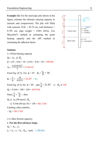
Example (1): For the steel pipe pile shown in the
figure, estimate the ultimate carrying capacity in
(tension and compression). The pile will filled
with concrete. O.D. = 45.72 cm, wall thickness =
0.792 cm, pipe weight = 0.861 kN/m. Use
Meyerhof’s method in estimating the point
bearing capacity and the API method in
estimating the adhesion factor.
Solution
( i ) Point bearing capacity
Qb = Ab . ̅. ́
̅ = (19 ‒ 9.8) × 10 + (19.6 ‒ 9.8) × 10 = 190 kPa
Ab = = 0.164 m2
From Fig. (8.7); For ϕ = 35ᵒ , R2 = = 10
R1 = = = 21.87 > R2
From Fig. (8.7); for ϕ ˃ 30ᵒ , and = 21.87 ́ 150
Qb = 0.164 × 190 × 150 = 4674 kN
Since, ˃ ; then
Qb Ab (50 tan ϕ ). ́
0.164 (50 tan 35) × 150 = 861.3 kN
Limiting value controls;
⸫ Qb = 861.3 kN
( ii ) Skin friction capacity;
For the first soil layer (top);
Qs1 = As1 . fs1
fs1 = α1 . c1 + k1 . ̅ . tanδ1 ≤ 100 kPa
ϕ = 20 ᵒ
c = 25 kPa
γ = 19 kN/m3
10
m
ϕ = 35 ᵒ
γt = 19.6 kN/m3
W.T.
3
m
10
m
5
m
Clayey sand
Dense sand
- 2. Foundation Engineering 2
From Table (8.3); for steel pile and clayey sand soil; k1 = 0.5 and δ1 = 20
̅ = (19 ‒ 9.8) × 5 = 46 kPa
From Fig. (8.9); for c1 = 25 kPa ; α1 = 1.0
fs1 = 1.0 × 25 + 0.5 × 46 × tan 20 = 33.37 kPa < 100 kPA o.k.
As1 = π × 0.4572 × 10 = 14.363 m2
Qs1 = 14.363 × 33.37 = 479.3 kN
For the second soil layer (bottom)
Qs2 = As2 . fs2
fs2 = α2 . c2 + k2 . ̅ . tanδ2 ≤ 100 kPa
For sand; α2 . c2 = 0
From table (8.3); For steel pile and dense sand, k2 = 1 , and δ2 = 20
̅ = (19 ‒ 9.8) × 10 + (19.6 ‒ 9.8) × 5 = 141 kPa
fs2 = 1 × 141 × tan 20 = 51.3 kPa < 100 kPa O.k.
As2 = π × 0.4572 × 10 = 14.363 m2
Qs2 = 14.363 × 51.3 = 736.8 kN
Qs = Qs1 + Qs2 = 479.3 + 736.8 = 1216.1 kN
Qu = Qb + Qs = 861.3 + 1216.1 = 2077.4 kN
Tu = W + Qs
W = Wsteel + Wconc.
Wsteel = 28 × 0.861 = 24.108 kN
I.D. = 0.4572 ‒ 2 × 0.00792 = 0.44136 m
Wconc. = [28 × × (0.44136)2
] × 24 = 102.812 kN
W = 24.108 + 102.812 = 126.92 kN
Tu = 126.92 + 1216.1 = 1343.02 kN
- 3. Foundation Engineering 3
Example (2): For the soil condition shown,
estimate the pile length required to carry an
ultimate load Qu = 5000 kN.
Solution
( i ) Point bearing capacity
Qb = Ab ( ̅. ́ ) ≤ Ab (11000) kN
Assume the limiting value controls;
Qb = Ab (11000) = (0.4)2
× 11000 = 1760 kN
( ii ) Skin friction capacity
For the first layer;
Qs1 = As1 . fs1
fs1 = α1 . c1 + k1 . ̅ . tanδ1 ≤ 100 kPa
For sand; α1 . c1 = 0
̅ = 17.5 × 5 = 87.5 kPa
fs1 = 0.7 × 87.5 × tan (0.75 × 30) = 25.4 kPa < 100 kPa o.k.
Qs1 = (4 ×0.4 × 10) × 25.4 = 406.4 kN
For the second soil layer
Qs2 = As2 . fs2
fs2 = k2 . ̅ . tanδ2 ≤ 100 kPa
̅ = 17.5 × 10 + × 19.5 = 175 + 9.75 L
fs2 = 1 × (175 + 9.75 L) × tan (0.75 × 35) = 86.3 + 4.8 L
Assume the limiting value controls for fs2 (fs2 = 100 kPa)
ϕ = 30 ᵒ
γ = 17.5 kN/m3
ks = 0.7
20
m
Concrete pile
(0.4 m × 0.4 m)
10
m
Sand
Sand
ϕ = 35 ᵒ
γ = 19.5 kN/m3
ks = 1.0
L
Qu
- 4. Foundation Engineering 4
Qs2 = (4 ×0.4 × L) × 100 = 160 L kN
But; Qu = Qb + Qs1 + Qs2 = 5000 kN
Or Qs2 = 5000 1760 406.4 = 2833.6 kN
2833.6 = 160 L L = 17.71 m
⸫ The total length = 27.71 m
Check for the assumptions;
( 1 ) Check ̅. ́ ;
From Fig. (8.5) ; = = 69.3 < 70
ϕ = 35 ᵒ ́ = 45
̅. ́ = (10 × 17.5 + 17.71 ×19.5) × 45 = 23415.5 kPa ˃ 11000 kPa o.k.
( 2 ) Check fs2 ;
fs2 = 86.3 + 4.8 L = 86.3 + 4.8 × 17.71 = 171.3 kPa ˃ 100 kPa o.k.
- 5. Foundation Engineering 5
Example (3-H.W.): Find the Allowable
axial load for the driven pile shown taking
Fs = 2.0. The elevation of W.T. ranged
between the two levels (105-108) during
the year.
Pile diameter = 0.5 m
Pile length = 20 m
Solution
( i ) Point bearing capacity
Qb = Ab ( ̅. ́ ) ≤ Ab (11000) kN
̅ = 17 × 2 + (17 ‒ 9.8) × 6 + (20 ‒ 9.8) × 4 + (19 ‒ 9.8) × 8 = 191.6 kPa
̅. ́ = 191.6 × 23.18 = 4441.3 kPa < 11000 kPa o.k.
Qb = (0.5)2
× 4441.3 = 872.0 kN
( ii ) Skin friction capacity;
For the first layer;
Qs1 = As1 . fs1
fs1 = α1 . c1 = 1 × 70 = 70.0 kPa ≤ 100 kPa
Qs1 = (π ×0.5 × 8) × 70 = 879.6 kN
For the second layer;
Qs2 = As2 . fs2
fs2 = α2 . c2 = 0.45 × 180 = 81 kPa ≤ 100 kPa
Qs2 = (π ×0.5 × 4) × 81 = 508.9 kN
N.C.clay
cu = 70 kPa
γt = 17 kN/m3
α = 1
+ 110
+ 102
+ 98
O. C. clay.
cu = 180 kPa
Deep sandy layer
γt = 19 kN/m3
= 32ᵒ
𝑁𝑞
́ = 23.18
ks = 1.5
tan δ = 0.5
γt = 20 kN/m3
α = 0.45
W.T. +108
- 6. Foundation Engineering 6
For the third layer;
Qs3 = As3 . fs3
fs3 = k3 . ̅ . tanδ3 ≤ 100 kPa
̅ = 17 × 2 + (17 ‒ 9.8) × 6 + (20 ‒ 9.8) × 4 + (19 ‒ 9.8) × 4 = 154.8 kPa
fs3 = 1.5 × 154.8 × 0.5 = 116.1 kPa > 100 kPa
⸫ fs3 = 100 kPa
Qs3 = (π ×0.5 × 8) × 100 = 1256.6 kN
Qu = Qb + Qs1 + Qs2 + Qs3 = 872 + 879.6 + 508.9 + 1256.6 = 3517.1 kN
Qa = = = 1758.6 kN
- 7. Foundation Engineering 7
Example (4-HW): For the driven pile shown in the
figure, determine:
a- The length of pile for allowable net pullout
resistance (Ta)net = 160kN with a safety factor
Fs = 2.7 .
b- The allowable compressive load for the same
value of safety factor.
Solution
( a ) Tu = Wp + Qs
(Tu)net = Qs
(Ta)net = = = 160 kN
Qs = 2.7 × 160 = 432 kN
Qs = Qs1 + Qs2
For the first layer (Soft clay)
Qs1 = As1 . fs1
α1 = 1 (soft clay)
fs1 = 1 × 20 = 20 kPa ≤ 100 kPa
Qs1 = (0.3 × 4 × 10) × 20 = 240 kN
⸫ Qs2 = Qs ‒ Qs1 = 432 ‒ 240 = 192 kN
For the second layer (Stiff clay)
Qs2 = As2 . fs2
fs2 = α2 . c2
From Table (8.2, case 2), assume 8 < PR ≤ 20 ;
⸫ α2 = 0.4
fs2 = 0.4 × 80 = 32 kPa ≤ 100 kPa
Qs2 = (0.3 × 4 × L) × 32 = 192 kN L = 5.0 m
Check for PR;
PR = = = 16.67 < 20 ok
Total pile length = 10 + 5 = 15m
10
m
0.3 m × 0.3 m
L
W.T.
Stiff clay
c = 80 kPa
𝛾 = 9.8 kN/m3
Soft clay
c = 20 kPa
𝛾 = 8.8 kN/m3
- 8. Foundation Engineering 8
( b ) Qu = Qb + Qs
Qb = Ab ( c ́ + ̅. ́ )
For clayey soils, Ø = 0, hence, ́ = 9 ( = 16.67 > 5 ok )
Qb = (0.3)2
× (80 × 9) = 64.8 kN
Qu = Qb + Qs = 64.8 + 432 = 496.8 kN
Qa = = = 184.0 kN
Example (5): Estimate the allowable carrying capacity of a concrete pile for the
following data;
L = 18 m , Wp = 3.5 kN/m , pile cap wt. = 7.6 kN
Double acting hammer; Wr = 60 kN , s = 0.5m/25 blows
Eh = 33.14 kN.m
Solution
S = = 20 mm/blow
Wp = 3.5 × 18 + 7.6 = 70.6 kN
a. ENR formula
Pu = = = 245 kN
b. BBC formula
= = 1.18 > 1.0 ok
Pu =
√
=
√
= 211.8 kN
![Foundation Engineering 2
From Table (8.3); for steel pile and clayey sand soil; k1 = 0.5 and δ1 = 20
̅ = (19 ‒ 9.8) × 5 = 46 kPa
From Fig. (8.9); for c1 = 25 kPa ; α1 = 1.0
fs1 = 1.0 × 25 + 0.5 × 46 × tan 20 = 33.37 kPa < 100 kPA o.k.
As1 = π × 0.4572 × 10 = 14.363 m2
Qs1 = 14.363 × 33.37 = 479.3 kN
For the second soil layer (bottom)
Qs2 = As2 . fs2
fs2 = α2 . c2 + k2 . ̅ . tanδ2 ≤ 100 kPa
For sand; α2 . c2 = 0
From table (8.3); For steel pile and dense sand, k2 = 1 , and δ2 = 20
̅ = (19 ‒ 9.8) × 10 + (19.6 ‒ 9.8) × 5 = 141 kPa
fs2 = 1 × 141 × tan 20 = 51.3 kPa < 100 kPa O.k.
As2 = π × 0.4572 × 10 = 14.363 m2
Qs2 = 14.363 × 51.3 = 736.8 kN
Qs = Qs1 + Qs2 = 479.3 + 736.8 = 1216.1 kN
Qu = Qb + Qs = 861.3 + 1216.1 = 2077.4 kN
Tu = W + Qs
W = Wsteel + Wconc.
Wsteel = 28 × 0.861 = 24.108 kN
I.D. = 0.4572 ‒ 2 × 0.00792 = 0.44136 m
Wconc. = [28 × × (0.44136)2
] × 24 = 102.812 kN
W = 24.108 + 102.812 = 126.92 kN
Tu = 126.92 + 1216.1 = 1343.02 kN](data:image/gif;base64,R0lGODlhAQABAIAAAAAAAP///yH5BAEAAAAALAAAAAABAAEAAAIBRAA7)