Mechanics and Materials I Lecture on Loading and Support Conditions
•
0 gostou•263 visualizações


Recomendados
Mais conteúdo relacionado
Mais procurados
Mais procurados (13)
Destaque
Destaque (20)
Semelhante a Mechanics and Materials I Lecture on Loading and Support Conditions
Semelhante a Mechanics and Materials I Lecture on Loading and Support Conditions (20)
Mais de Mohamed Yaser
Mais de Mohamed Yaser (20)
Mechanics and Materials I Lecture on Loading and Support Conditions
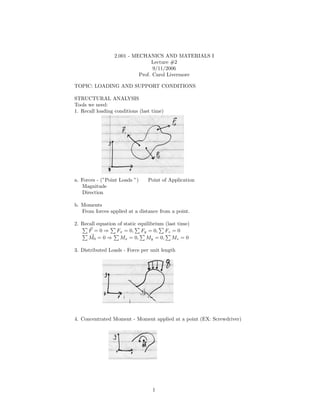
- 1. 2.001 - MECHANICS AND MATERIALS I Lecture #2 9/11/2006 Prof. Carol Livermore TOPIC: LOADING AND SUPPORT CONDITIONS STRUCTURAL ANALYSIS Tools we need: 1. Recall loading conditions (last time) a. Forces - (”Point Loads ”) Point of Application Magnitude Direction b. Moments From forces applied at a distance from a point. 2. Recall equation of static equilibrium (last time) F = 0 ⇒ Fx = 0, Fy = 0, Fz = 0 M0 = 0 ⇒ Mx = 0, My = 0, Mz = 0 3. Distributed Loads - Force per unit length 4. Concentrated Moment - Moment applied at a point (EX: Screwdriver) 1
- 2. FREE BODY DIAGRAMS Draw like a mechanical engineer Fixed Support Cannot translate horizontally or vertically. Cannot rotate. Pinned Support - Cannot translate. - Free to rotate. Pinned on Rollers - Cannot translate in y. - Can translate in x. - Free to rotate. REACTIONS: (Forces applied by a support) 2
- 3. No ⇒ can apply Rx . ↑↓⇒ can apply Ry . No rotate ⇒ can apply M . So: Need Rx , Ry , M Need Rx , Ry 3
- 4. Need Ry OTHERS: CABLE: SMOOTH SUPPORT: EXAMPLE: DIVING BOARD Find reactions from the supports for this structure. 4
- 5. 1. How to draw a Free Body Diagram (FBD) i. Remove all external supports. ii. Draw all relevant dimensions. iii. Depict all external forces and moments. iv. Coordinate system. 2. Apply the equations of equilibrium. Fx : RAx = 0 Fy : −P + RAy = 0 MAz : MA − LP + (RAx )(0) + (RAy )(0) = 0 3. Solve. RAx = 0 RAy = P MA = LP 4. Check ⇒ looks good! EXAMPLE: 5
- 6. Draw FBD. Apply equilibrium. Fx : RAx = 0 L Fy : RAy + RBy − 0 (−q0 )dx =0 L q0 L2 MA : RBy L + 0 (−q0 )xdx = 0 = RBy L − 2 Solve. RAx = 0 2 RBy = q0 L = q0 L ⇒ RBy = q0 L 2L 2 2 RAy + q0 L − q0 L = 0 ⇒ RAy = q0 L 2 2 Check. ⇒ looks good! EXAMPLE: PLANAR TRUSS 6
- 7. Q: What are the forces on each member? Approach: Look at whole structure. Look at each piece individually. FBD of Whole Structure RB = RBxˆ + RBy ˆ i j Equations of Equilibrium: Fx = 0 R Bx + P = 0 Fy = 0 R Ay + R B y = 0 MA = 0 RBy l + (P )(− sin θ)l = 0 OR rAC × P + rAB × RB = 0 Solve. RBx = −P RBy = P sin θ RAy = −P sin θ Check. 7