1. Arc Welding is Essential to the Success
of a Unique Structure
By Miklos Peller, P.E.
Vice President
Tilden, Lobnitz & Cooper, Inc.
Cleveland, Ohio
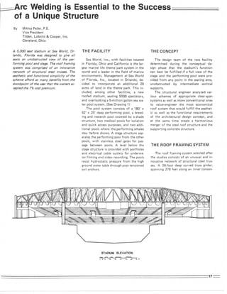
A 5,000 seat stadium at Sea World, Or-
lando, Florida was designed to give all
seats an unobstructed view of the per-
forming pool and stage. The roof framing
system was comprised of an innovative
network of structural steel trusses. The
aesthetic and functional simplicity of the
scheme afford so many benefits from the
standpoint of the user that the owners ac-
cepted the 7% cost premium.
THE F A C I L I T Y
Sea World, Inc., with facilities located
in Florida, Ohio and California is the lar-
gest marine life theme park system in the
world and a leader in the field of marine
environments. Management at Sea World
of Florida, Inc., located in Orlando, de-
cided to incorporate an additional 20
acres of land in the theme park. This in-
cluded, among other facilities, a new
roofed stadium, seating 5000 spectators,
and overlooking a 5-million gallon sea wa-
ter pool system. (See Drawing 1)
The pool system consists of a 180' x
92' X 35' deep performing pool, a breed-
ing and research pool covered by a shade
structure, two medical pools for isolation
and quick access purposes, and two addi-
tional pools where the performing whales
stay before shows. A stage structure sep-
arates the performing pool from the other
pools, with stainless steel gates for pas-
sage between pools. A level below the
stage structure is provided with portholes
and electrical cable outlets for underwa-
ter filming and video recording. The pools
resist hydrostatic pressure from the high
ground water table through post-tensioned
soil anchors.
T H E CONCEPT
The design team of the new facility
determined during the conceptual de-
sign phase that the stadium's function
can best be fulfilled if a full view of the
stage and the performing pool were pro-
vided from any point in the seating area,
unobstructed by intermediate vertical
supports.
The structural engineer analyzed var-
ious schemes of appropriate clear-span
systems as well as more conventional ones
to value-engineer the most economical
roof system that would fulfill the aesthet-
ic as well as the functional requirements
of the architectural design concept, and
at the same time create a harmonious
merger of the steel roof structure and the
supporting concrete structure.
THE R O O F FRAMING SYSTEM
The roof framing system selected after
the studies consists of an unusual and in-
novative network of structural steel trus-
ses. A 26-foot deep curved truss girder,
spanning 276 feet along an inner concen-
2. trie circle with a 93-foot radius, resting
on two massive 6'0" round concrete piers
well outside the angle of vision from any
seat. Radial trusses spanning 91'6",
tapered in depth from 10' to 26' and spa-
ced on 10-degree intervals, frame into the
truss girder. Roof purlins are spaced at
11'5" centers, and support an acoustical
metal deck with a regular-weight concrete
roof fill over it. The cost of this novel fra-
ming system was merely 7% higher than a
conventional column-supported roof. The
aesthetics and functional simplicity of the
scheme, however, afforded so many bene-
fits from the standpoint of the user that
the owners accepted the 7% cost premium.
THE S T R U C T U R A L DESIGN
Since the girder truss is spanning along
a curve, it requires torsional restraint a-
long its length to maintain stability. The
radial trusses are designed to provide this
restraint. Even though each radial truss
carries an equal tributary roof area, the
bending moments, shears and reactions
are influenced by the torsional restraint
requirement of the girder truss. Lateral
design forces on the roof structure are re-
sisted by a 25-foot high, 515-foot long
curved concrete wall along the outer con-
centric circle with a radius of 184'6", and
the reinforced concrete seating frame.
Aero-dynamic analysis indicated that
the uplift forces on the roof structure
were of such magnitude under hurricane
loading that weight in the form of a con-
crete slab over the roof deck was needed
to provide adequate gravity load to resist
uplift and to minimize stress reversals in
the trusses. Acoustical engineers at the
same time utilized the mass of this con-
crete fill to eliminate background noise
resulting from heavy rains which are typ-
ical in Florida.
The resulting structure is a three-
dimensional space frame, made up of a
girder truss curved in plan (weighing ap-
proximately 100 tons), 17 radial trusses
framing into the truss girder at 10° inter-
vals (each weighing approximately 9.5
tons), bottom chord struts and sloping
bridging struts (weighing approximately
50 tons), and roof purlins (weighing ap-
proximately 60 tons). A curved eave
truss was created adjacent to the truss
girder bottom chord, designed to stab-
ilize the framework against secondary for-
ces. Top chords are stabilized by the dia-
phragm action of the concrete slab, made
composite with the trusses by the use of
welded shear studs.
Standard rolled shapes were selected
for truss members, and round pipe sec-
tions were specified for bracing members,
dictated by aesthetic considerations and
equal strength requirements in any direc-
tion perpendicular to member axes.
THE D E T A I L S
Given the multitude of member direc-
tions, a major part of the structural de-
sign effort was focused on the details of
the member connections. A majority of
the structural nodes have nine con-
verging members from various directions
at various angles, complicated by the pre-
sence of sliding expansion joints at cer-
tain locations. The detailing task involved
five considerations in addition to load
transfer requirements:
1. the necessity to keep the connec-
tions simple and concise so that
they would not dominate the
aesthetics of the structure;
2. the minimization of connection ma-
terial and their fabrication in order
to keep the cost of this structural
scheme competitive with conven-
tional short-span frames;
3. the facilitating of shop fabrication
and field erection;
4. the minimization of materials and
surfaces exposed to corrosive salt
spray exposure;
5. the final goal of a simple, aesthet-
ically organized system.
W E L D E D CONNECTIONS
The above considerations led to the
conclusion that welded connection details
are the only appropriate details to achieve
the desired results. Although welded trus-
ses are common, the presented framing
system is unique in view of the unusual
force distribution and the unusual frame
geometry. The system of welded connec-
tions as designed resulted in simple yet
disciplined structural nodes, emphasizing
the lightness, effortlessness and airy ap-
pearance of the frame which was one of
the aesthetic design criteria. (See Figure 1)
Minimizing connection materials by
judicious use of welded details meant less
fabrication, reduced fabrication time and
minimized material costs. The designers
calculated that approximately 15 tons of
fabricated connection material and about
25,000 bolt hole preparations and 10,000
3. Figure 1- A view of the roof structure, showing the radial trusses and the girder truss.
bolt installations were elinriinated from
the structure by designing welded con-
nections. Shop fabrication was minimized
and simplified by the use of the indicated
welded details to such an extent that the
fabricator finished ahead of schedule.
Welded connections resulted in sub-
stantial reduction of finished surfaces and
interface surfaces and crevices, which
meant reduced painting costs and greater
confidence in the corrosion protection.
(See Drawing 2)
All of the welds, with the exception of
field splices, were made in the fabricator's
shop, under controlled conditions. The
specified quality control inspection of the
welds was also carried out in the shop.
Since the trusses were stored on the
ground, it was possible to postpone the
weld inspection to such time when nearly
all of the welds were completed, resulting
in reduced quality control costs.
All connections were conceived and
detailed as welded throughout with the
exception of the field connection of the
radial trusses to the main girder truss, and
the strut connections. These were de-
tailed as bolted for the following reason:
The radial trusses require the girder
truss for vertical support, and at the same
time the girder truss requires the strength
of the radial trusses for torsional support.
Four temporary support towers were
used during the erection of the truss gir-
der, resulting in five approximately equal
spans. Erection of the radial trusses pro-
ceeded from the end of the girder truss
toward its mid-span. The temporary tow-
ers were required to remain in place until
the entire trusswork and the bracing
beams were installed, due to the frame
geometry and the truly three-dimensional
structural behavior of the system. Since
time was critical and the erection towers
limited construction activity at ground
level, the erection of the roof structure
had to proceed rapidly, and the connec-
tion of the radial trusses to the girder
truss had to keep abreast of the erection.
The engineer selected bolted connection
for these, eliminating extensive testing of
welds at a critical time in the erection and
at the same time eliminating the need for
temporary welding platforms and ground
level protection from welding sparks.
Therefore, the structure was organized so
that no major structural welding was
done above ground at critical locations
and at critical times.
19:
4. D E T A I L S O F T H E
W E L D E D JOINTS
Details of the welding considered sev-
eral factors. One was the choice of mater-
ials. ASTM A 36 steel was used for struc-
tural shapes up to the W12 series, and
ASTM A 572 Grade 50 for W14 shapes.
Using various grades of steel minimized
abrupt thickness changes at welded spli-
ces. Another factor to be considered was
that the geometry of the joint should al-
low run-off of rain water. The orienta-
tion of the truss members and that of the
stiffener plates were partially dictated by
this consideration.
The joint configuration was organi-
zed to avoid overlapping of welds and to
minimize concentration of weld-related
residual stresses. Weld locations were
carefully selected and cope holes were ex-
tensively detailed. Abrupt changes in ad-
jacent material thicknesses were avoided.
(See Figure 2)
The chord butt splices in the truss gir- ^'^^ ^'^'^ ^^^"^^ '^^ Stadium
der were detailed with edge plates and
vertical stiffeners to avoid stresses from
secondary effects which would develop inforce and stiffen the chords at the spli- dary stresses at those locations, and the
a tri-axial tension stress state. Further- ces where they change direction in the same edge plates were used to connect the
more, the edge plates were detailed to re- curved truss, reducing undesired secon- radial trusses. (See Section 1, Drawing 2)
The dimensions of the completed trus-
ses ruled out their shipment as a comple-
ted unit. The fabricator and the engineer
worked out a system of field splices, en-
abling transportation. The fabricator
chose to completely assemble the truss in
the shop to assure good fit-up which con-
sideration was paramount in view of the
complex geometry and the specified
camber. Once assured of the fit-up, the
fabricator saw-cut the truss members at
the field splices, and prepared the cut
ends to specifications for a butt-welded
field splice. (See Drawing 2) This re-
sulted in truss segments of transportable
dimensions.
The design of the truss members was
rechecked for potential mid-length ec-
centricities allowed by field assembly tol-
erances. Upon delivery of the trusses to
the project site, they were reassembled on
the ground in a jig and rewelded at the
field splice locations. Following accept-
ance of the field splices after testing, the
trusses were erected in their complete
configuration. The field splices are not
visible, their only mark is the round web
Figure 2-An interior joint at a slide-bearing expansion joint. Note field splice to the cope holes which were left open in the
left of the joint. Round pipe sections are horizontal and diagonal bracing members. final product.
20:
5. Drawing 2
Q U A L I T Y C O N T R O L
Certification was required for all wel-
ders for the detailed weld types. All welds
needed to pass a visual inspection for
AWS D1.1 compliance. Magnetic Particle
Inspection ASTM E 109 was required for
the root pass of all full-penetration butt
welds. Ultrasonic Inspection ASTM E
was required on all completed full-pene-
tration welds and adjacent heat-affected
zones in the base metal, and also for fillet
welds 3/8" or larger and for all welds that
failed to pass visual inspection. The full
procedure was required to be repeated in
the cases of welds that failed to pass the
test. The same procedure was prescribed
for the butt welds in the field splices.
In addition to the tests on the welds,
steel for the W14 sections were specified
with a low transition temperature based
on Charpy V-notch impact tests.
Corrosion protection of the finished
structure was of utmost concern since the
structure is exposed to a corrosive envi-
ronment. Development of corrosion or
corrosion cells in highly stressed welded
connections would be detrimental. Com-
mercial blast cleaning surface preparation,
a zinc-rich primer paint and a compatible
epoxy-based finish paint was required in a
dry film thickness of 2.0 to 3.5 mills.
THE R E S U L T
Welded connections achieved what was
expected: the stadium roof structure eco-
nomically achieved a clear statement of
its purpose. The audience has an unob-
structed view of the stage, and the ef-
fortlessly clean lines and simple joint
nodes and connections of the truss mem-
bers enhance and complement the pri-
mary function of the stadium.