SlideShare uma empresa Scribd logo
1 de 9
Baixar para ler offline
(12) United States Patent
Agrawal et al.
(54) SYSTEM, METHOD, AND APPARATUS FOR
IN-SITU ACOUSTIC EMISSION
MONITORING OF BURNISH HEADS IN
PRODUCTION DURING MAGNETIC MEDIA
CLEANING OR BURNISH PROCESS
(75) Inventors: Parul Agrawal, Saratoga, CA (US);
Bradley Frederick Baumgartner, Los
Banos, CA (US); Norman Chu, San
Francisco, CA (US); Charles Lee, San
Jose, CA (US); Tony Mello, San Jose,
CA (US); Christopher Ramm, San
Jose, CA (US); Bob Clyde Robinson,
Hollister, CA (US)
(73) Assignee: Hitachi Global Storage Technologies
Netherlands B.V., Amsterdam (NL)
( *) Notice: Subject to any disclaimer, the term of this
patent is extended or adjusted under 35
U.S.C. 154(b) by 0 days.
(21) Appl. No.: 10/881,145
(22) Filed: Jun.30,2004
(51) Int. CI? ............................................... B24B 49/00
(52) U.S. Cl. ............................................. 451/8; 451/63
(58) Field of Search ................................ 451!5, 6, 8, 9,
451!41, 63, 290; 73/105; 29/90.1, 603.16
(56) References Cited
U.S. PATENT DOCUMENTS
5,220,470 A
5,488,857 A
5,675,462 A
5,824,920 A
5,917,726 A *
5,939,624 A
5,942,680 A
6,290,573 B1
17
6/1993 Ananth et a!.
2/1996 Homma et a!.
10/1997 Ayabe
10/1998 Sugimoto et a!.
6/1999 Pryor .......................... 700/95
8/1999 Smith, Jr.
8/1999 Boutaghou
9/2001 Suzuki
IIIIII 1111111111111111111111111111111111111111111111111111111111111
US006935925Bl
(10) Patent No.: US 6,935,925 Bl
(45) Date of Patent: Aug. 30, 2005
6,296,552 B1 * 10/2001 Boutaghou eta!. ........... 451!41
6,503,132 B2 1!2003 Ekstrum et a!.
6,526,639 B2 3/2003 Duan eta!.
6,536,265 B1 3/2003 Hanchi eta!.
6,580,572 B1 * 6/2003 Yao et a!. ..................... 360/25
FOREIGN PATENT DOCUMENTS
JP 55077037 6/1980
JP 56083843 7/1981
JP 1310861 12/1989
JP 9016593 1!1997
JP 11037748 2/1999
OTHER PUBLICATIONS
"Zero Pitch Burnish Head", IBM Technical Disclosure Bul-
letin, Sep. 1992, 92A 62522/R08920217, p. 421.
"A Correction Technique for Magnetic Disk Fly Heights",
IBM Technical Disclosure Bulletin, Feb. 1990, 90A 63578/
R08870240, Pub. No. 310.
(Continued)
Primary Examiner-Jacob K. Ackun, Jr.
(74) Attorney, Agent, or Firm-Bracewell & Giuliani LLP
(57) ABSTRACT
An in-situ technique for the acoustic emission monitoring of
burnish heads while they are cleaning or burnishing mag-
netic media is described. The burnishing process is moni-
tored and controlled to identify interaction or contact
between the head and media due to, for example, burnish
head damage, substrate curvature problems, and lube pick-
up problems. A piezoelectric sensor is mounted on the
burnish arm that holds the burnish heads. When head-disk
interaction occurs, stress waves travel through the head to
the sensor and an amplified signal is gathered in a tester
database as an acoustic emission. Abnormal conditions will
trigger an unusual emission that is detected to trigger an
alert.
17 Claims, 3 Drawing Sheets
Amplifier
Data Acquisition
System
23
US 6,935,925 Bl
Page 2
01HER PUBLICATIONS
"Intelligent Burnishing System Using a Cognizant Burnish
Head", IBM Technical Disclosure Bulletin, Apr. 1987, 87A
62638/49-240 P300/SA8850248, Pub. No. 276.
"Method of Testing Burnishing Magnetic Heads", IBM
Technical Disclosure Bulletin, Sep. 1984, 84A 62267/49-
240 P15/GE8820051, p. 2315.
* cited by examiner
U.S. Patent Aug. 30, 2005 Sheet 1 of 3
17
Burnish Arm
FIG. 1
33
FIG. 2
US 6,935,925 Bl
Amplifier
Data Acquisition
System
Amplitude Scale
35
23
U.S. Patent Aug. 30, 2005 Sheet 2 of 3 US 6,935,925 Bl
0.00 -;r----;--;----;---;--;--;-----:---:---,--:----,
-5760
-11519
-17278
-23037
-28796
-34556
-40315
-40074
-51833
,57592 ..":l-""""'.......""""""........- .................of-r.T"T"T'f-T"''"'T"T""i--T-r...,....,..,"""T"T'~~r-r+"'T'T""rrl
0 2878 5756 ·8634 11512 14390 17268 20146 23024 25902 28780
106 . . ' ' ' ' ' ': I I I I I I I I
95.9 ---------~- --------~--------l-------..-~--------~ --------- --------~---------~-- ------~---------
: : : ! : : : : :
85 8 ---------~---------!-- -------:-------- ..:..-------- ~- ------- --------!---------:..--------~---------. ; : : : : : : : :
75.7 ---------~- --------~- -------~-- -------~- -------i-------- --------~- --------~-- ------~ ---------: I I ' I I I I I
65.6 : ••••••••-~- •••••••-~- ••••••-~ ••••••••-~ ••••••••f•••••••• I ••• •• •• -~ • • • • •• • _. -~•••••• ••1••• •• ••.,...
: I I 4 I I I I I j
55 5 ---------~-- ------.:.....---....--~- .................:.....--------~ ----.......... :..........--~- --..-----~-- ------~ ---------
. ~ : : : : : : : : :
45.4 =....-·-··--t-·......----~ .............--1---------r--------t-------- ;--------1---------r--------1---------
35.3 : ---------r---------~-- ------1---------~- -------~- ------- :--------~- --------r--------~---------= : : : : : : : : :
!~~ ~::::::::!::::::::r::+I1
r:::::::::::::::::::::::!::::::::r:::::F::::::
43
I
AE output,
OD
Noise
0 2878 5756 8634 11512 14390 17268 20146 23024 25902 28780
FIG. 3
U.S. Patent Aug. 30, 2005 Sheet 3 of 3 US 6,935,925 Bl
51
v
4.0
3.5
3.0
Load ~--Head in Contact /- ...
57
Unload
-::s
.e- 2.5::s
0
Q) 2.0
en
.B
~ 1.5
1.0
0.5
0.0
_oLI!..oM<tl..ll.
vss ~ ~
~
Head
-- Flying - (53
1.....dt .,.., .l.JI!I.t .~1o.....,~Jii,,,._.IJIJI ,.,A .1.... ._,_ ....._,,.L- , ••
16.0 6.0
Linear Velocity (m/s)
FIG. 4
16.0
....
US 6,935,925 Bl
1 2
response that generally scales with increasing size of the
asperity. If the voltage response exceeds a predetermined
level, the disk is rejected.
One way to reduce such disk defects is to burnish the
SYSTEM, METHOD, AND APPARATUS FOR
IN-SITU ACOUSTIC EMISSION
MONITORING OF BURNISH HEADS IN
PRODUCTION DURING MAGNETIC MEDIA
CLEANING OR BURNISH PROCESS
BACKGROUND OF THE INVENTION
1. Technical Field
5 disks. A thin film disk head burnish process removes the disk
surface debris and asperities that are introduced by pre- and
post-sputter processes. As stated above, such debris and
asperities can reduce disk glide yield and cause other
significant disk drive performance problems. The burnish
The present invention relates in general to improved
processing of disk drive components and, in particular, to an
improved system, method, and apparatus for monitoring a
condition of a burnish head during a magnetic media clean-
ing and/or burnish process.
10 process is utilized on thin film media to remove asperities
and loose particles before it can go for glide and magnetic
certification tests. Burnishing is typically performed in two
steps: a tape burnish process followed by a head burnish.
Presently, the burnish heads themselves are not monitored or
2. Description of the Related Art
Generally, a data access and storage system consists of
one or more storage devices that store data on magnetic or
optical storage media. For example, a magnetic storage
device is known as a direct access storage device (DASD) or
15 evaluated while in operation. In particular, there have been
no attempts to maintain the status of burnish heads at the
media glide and magnetic certification testers. Thus, it
would be desirable to be able to better understand and
evaluate the condition of burnish heads during operation.
a hard disk drive (HDD) and includes one or more disks and 20
a disk controller to manage local operations concerning the
disks. The hard disks themselves are usually made of
aluminum alloy or a mixture of glass and ceramic, and are
covered with a magnetic coating. Typically, two or three
disks are stacked vertically on a common spindle that is 25
turned by a disk drive motor at several thousand revolutions
per minute (rpm).
SUMMARY OF THE INVENTION
One embodiment of a system, method, and apparatus for
in-situ, acoustic emission (AE) monitoring of burnish heads
during manufacturing production, while they are cleaning
and/or burnishing magnetic media, is described. The present
invention effectively monitors and controls the burnishing
process to identify interaction or contact between the head
and media due to burnish head damage, substrate curvature
problems, excessive lubricant pick-up by the slider, etc. This
technique utilizes a piezoelectric sensor that is mounted on
the burnish arm that holds the burnish heads. Whenever any
head-disk interaction occurs, the stress waves travel through
the burnish head to the sensor and the amplified signal is
A typical HDD also includes an actuator assembly. The
actuator moves magnetic read/write heads to the desired
location on the rotating disk so as to write information to or 30
read data from that location. Within most HDDs, the mag-
netic read/write head is mounted on a slider. A slider
generally serves to mechanically support the head and any
electrical connections between the head and the rest of the
disk drive system. The slider is aerodynamically shaped to
glide over moving air in order to maintain a uniform distance
from the surface of the rotating disk, thereby preventing the
head from undesirably contacting the disk.
35 gathered in the tester database as an AE.
This AE information is utilized to serve several objec-
tives. If everything is operating normally while a burnish
head is flying above the media, there will not be a significant
signal and the AE amplitude will be at a noise floor level.Typically, a slider is formed with an aerodynamic pattern
of protrusions (air bearing design) on its air bearing surface
(ABS) that enables the slider to fly at a constant height close
to the disk during operation of the disk drive. A slider is
associated with each side of each platter and flies just over
the platter's surface. Each slider is mounted on a suspension
to form a head gimbal assembly (HGA). The HGA is then
attached to a semi-rigid actuator arm that supports the entire
head flying unit. Several semi-rigid arms may be combined
40 However, a number of activities may generate an unusual
signal that is detected by the system. These abnormal
activities include, for example: (a) the head is picking up
significant amount of lubricant that affect flyability; (b) the
head is damaged; (b) substrate curvature or chamfer prob-
to form a single movable unit having either a linear bearing
or a rotary pivotal bearing system.
45 lems; and (d) the disk has an unusual amount of contami-
nation or mounds. When an event such as these is detected,
a system and/or operator is alerted to take action regarding
the problem, such as eliminating the damaged burnish head.
This could prevent damaging significant number of disks
To successfully achieve file performance, the heads must
fly steadily at a given fly height over the disk with minimal
variations. Since the variations in fly height are dependent
50 and help tremendously in controlling the quality of the disks.
on the various sensitivities of the fly height to the process
parameters as well as the variability of the parameters, tight
process control is mandatory to minimize such variations. 55
Common dominant process parameters affecting fly height
include gram load, pivot location, crown and etch depths.
The presence of asperities on the surfaces of the disks is
a major factor that can have a deleterious effect on the
performance of disk drives. Asperities can contact the mag- 60
netic head as it flies at its normal height in a disk drive. For
this reason, a glide test is performed on finished disks to
detect asperities that might contact the magnetic head during
operation. In the test, a special glide head containing a
piezoelectric transducer (PZT) is flown over a disk at an 65
altitude or height that is below the normal drive fly height.
Glide head contact with an asperity creates a PZT voltage
In one embodiment, this in-situ monitoring technique
utilizes the AE sensors that detect head disk interaction. The
sensors are attached on the block arm that holds the burnish
heads. In the event of head disk interaction, the stress wave
travels via suspension to the head block and the sensors
picks up the signal. In one version, the signal is amplified
and monitored with a hardware and acquisition system, such
as a preamplifier and an amplifier, and the RMS voltage
output value is fed to the data acquisition system.
For production monitoring, the signal is picked up at the
ID, MD and OD tracks for 1,080 sectors on the media or
disk. The disk is identified by converting the cassette num-
ber and the slot number into a "Morse code." The intensity
of the signal is shown as a stripe next to the disk code and
a color scale scheme is used to represent the intensity of the
signal. Log files are also generated that contain the cassette
number, slot number, glide test information, test time, and
US 6,935,925 Bl
3
average value of signals obtained at the ID, MD and OD
locations. This method is useful in detecting (a) burnish head
interaction with the substrate ski jumps; (b) suspension
problems due to wrong alignment and dragging of the heads;
and (c) significant lubricant interaction with burnish heads.
The present invention can help in determining the radial
accessibility of burnish head at the outermost radius of the
disk. This method helps optimize the burnish head traverse
radius on the disk and avoid its interaction with disk
curvature and chamfer.
For hybrid burnish sliders, the present invention may be
used for spin-down characterization in order to decide the
operating point for sweeping as well as burnishing process.
For example, hybrid burnish heads may be characterized to
decide the operating velocities for sweeping and contact for
each burnish head at the manufacturing floor. This feature is
analogous to using a bump test for glide heads to decide their
operating velocities.
4
a relative magnitude of contact between the burnish head 17
and the magnetic media 11. A data acquisition system 23
receives and processes the signal 21 from the sensor 19. In
one embodiment, the sensor 19 comprises a piezoelectric
5 sensor for detecting stress waves traveling from the burnish
head 17 through the burnish arm 15 to the sensor 19, and the
signal is an acoustic emission (AE). In one embodiment, the
signal 21 feeds an RMS voltage output value to the data
acquisition system 23, and the data acquisition system 23
10 utilizes a preamplifier 27 and an amplifier 29 to amplify the
signal 21.
One type of burnish head flies in proximity to the disks
and is primarily used for cleaning the particles and loose
contamination therefrom. This type may not necessarily aid
15 in burnishing the asperities, such that any type of continuous
contact above the noise floor is bad. These heads cannot
make a steady contact with the disks. In normal situations,
the AE output for these heads would be at the noise floor.
The foregoing and other objects and advantages of the
present invention will be apparent to those skilled in the art, 20
in view of the following detailed description of the present
invention, taken in conjunction with the appended claims
and the accompanying drawings.
Any output above the noise floor for these heads indicates a
problem due to unnecessary head-disk interaction. For
example, the system shown in FIG. 1 detects the interaction
and signals an alert 25 (e.g., alerts the operator) for preven-
tive measures.
As shown in FIG. 2, the data acquisition system 23
BRIEF DESCRIPTION OF THE DRAWINGS
So that the manner in which the features and advantages
25 distinguishes between normal operating conditions 31 and
abnormal operating conditions 33 between the magnetic
media 11 and the burnish head 17 in order to detect a
problem with the burnish head 17. FIG. 2 represents aof the invention, as well as others which will become
apparent are attained and can be understood in more detail,
more particular description of the invention briefly summa- 30
rized above may be had by reference to the embodiment
thereof which is illustrated in the appended drawings, which
drawings form a part of this specification. It is to be noted,
however, that the drawings illustrate only an embodiment of
the invention and therefore are not to be considered limiting 35
of its scope as the invention may admit to other equally
effective embodiments.
typical graph obtained from the system of the present
invention depicting dozens of magnetic media 11 tested by
a single burnish head 17. Each line 35 on the right shows the
high value of an acoustic emission (AE) signal at an outer
diameter (OD) location on one of the disks. Such a consis-
tent and large number of lines 35 indicate problems with the
burnish head 17. For example, the sensor 19 may detect
damage to the burnish head 17, interaction with radial
curvature of the disks near their outer diameters, and accu-
mulation of lubricant on the burnish head 17. An alert 25,
such as a visual, audible, or electronic signal via computer,
to an operator is generated by the system regarding a
problem with the burnish head 17.
FIG. 1 is a schematic diagram of a burnish head in-situ
acoustic emission monitoring system for magnetic media
and is constructed in accordance with the present invention; 40
FIG. 2 is an acoustic emissions plot generated by the
system of FIG. 1 and is constructed in accordance with the
present invention;
Comparing FIGS. 2 and 3, the system monitors normal
operating conditions 31, which emit a baseline amplitude 41
(lower plot in FIG. 3) at a noise floor level, and abnormalFIG. 3 is an acoustic emissions plot for scanner position-
ing generated by the system of FIG. 1 and is constructed in
accordance with the present invention; and
FIG. 4 is a plot of spin-down and spin-up characteriza-
tions of burnish head in the system of FIG. 1 and 1s
constructed in accordance with the present invention.
DETAILED DESCRIPTION OF THE
INVENTION
Referring to FIG. 1, one embodiment of a system,
method, and apparatus for in-situ, manufacturing production
monitoring of burnish heads while they are cleaning and/or
burnishing magnetic media is disclosed. The present inven-
tion comprises a magnetic media 11 that rotates about an
axis 13 and a burnish arm 15 having a burnish head 17
mounted thereto. The burnish arm 15 positions the burnish
head 17 adjacent and in proximity to the magnetic media 11,
and pivotally moves the burnish head 17 relative to the
rotating magnetic media 11 for cleaning or burnishing the
magnetic media 11.
A sensor 19 is mounted to the burnish arm 15 for detecting
physical contact between the burnish head 17 and the
magnetic media 11. The sensor emits a signal 21 to identify
45 operating conditions 33, which emit a spike 43 in amplitude
that is significantly greater than the noise floor level. The
spike 43 happens to coincides at the OD of the magnetic
media 11, as shown in the upper plot 45 that depicts the
radial position of the burnish head 17 relative to the mag-
50 netic media 11.
A second category of head makes steady contact. These
heads are used in contact mode to burnish asperities. Hybrid/
contact or hybrid heads are capable to flying as well as
making steady contact on the disks. Hence, they could be
55 used for cleaning as well as burnishing small asperities. The
velocity of the heads is an important parameter when contact
with the disks is established so that the operating points for
flying as well as contact mode can be decided when they are
used in production. Typically AE output from these heads is
60 low amplitude and steadily increasing as velocity is
decreased. If the AE output makes a sudden high amplitude
jump then the head is not stable.
Referring now to FIG. 4, the present invention also aids
in determining the operating velocity for flying 53 and
65 contact mode 51 of hybrid burnish heads. The operating
velocity of a hybrid burnish head is characterized by: flying
the head 17 in proximity to the magnetic media 11, and then
US 6,935,925 Bl
5
reducing a speed of the magnetic media 11 until the sensor
19 detects contact with the magnetic media 11 that exceeds
the baseline amplitude 53.
The present invention also comprises a method of in-situ
monitoring of burnish heads 17 while they are cleaning or 5
burnishing magnetic media 11. The method comprises:
providing a magnetic media 11 (FIG. 1) and a burnish arm
15 having one of the burnish heads 17 described herein;
rotating a magnetic media 11 about an axis 13; cleaning
and/or burnishing the magnetic media 11 with the burnish 10
head 17; detecting contact 43 (FIG. 3) between the burnish
head 17 and the magnetic media; identifying a relative
magnitude of said contact between the burnish head 17 and
the magnetic media 11; and distinguishing between normal
and abnormal operating conditions 31, 33 (FIG. 2) between 15
the magnetic media 11 and the burnish head 17 to detect a
problem with the burnish head 17.
6
burnish head with disk radial curvature, and accumulation of
lubricant on the burnish head.
3. The system of claim 1, wherein the sensor comprises a
piezoelectric sensor for detecting stress waves traveling
from the burnish head through the burnish arm to the sensor,
and the signal is an acoustic emission.
4. The system of claim 1, wherein normal operating
conditions emit a baseline amplitude at a noise floor level,
and abnormal operating conditions emit a spike in amplitude
that is significantly greater than the noise floor level.
5. The system of claim 4, wherein the burnish head is a
hybrid/contact burnish head having an operating velocity
characterized for proximity flying and steady contact by:
flying the burnish head in proximity to the magnetic media,
reducing a speed of the magnetic media until the sensor
detects contact with the magnetic media that exceeds the
baseline amplitude.
6. The system of claim 1, further comprising an alert
20
generated by the system regarding a problem with the
burnish head.
The method further comprises detecting at least one of
damage to the burnish head 17, interaction of burnish head
with disk's radial curvature (e.g., determining a farthest OD
radius on the disk that the burnish head can reach without
interacting with disk chamfer or radial curvature of the disk),
and accumulation of lubricant on the burnish head 17. The
method may comprise using a piezoelectric sensor 19 for
detecting stress waves traveling from the burnish head 17
through the burnish arm 15 to the sensor 19. The signal 21
may be an acoustic emission detected by a data acquisition
system 23 to receive and process a signal 21 from the
piezoelectric sensor 19. The data acquisition system 23
emits a baseline amplitude 41 at a noise floor level in 30
response to normal operating conditions 31, and a spike 43
in amplitude in response to abnormal operating conditions
33 that is significantly greater than the noise floor level.
In addition, the method characterizes an operating veloc-
7. The system of claim 1, wherein the signal feeds an
RMS voltage output value to the data acquisition system,
and the data acquisition system utilizes a preamplifier and an
25 amplifier to amplify the signal.
8. A method of in-situ monitoring of burnish heads while
they are cleaning or burnishing magnetic media, comprising:
(a) providing a magnetic media and a burnish arm having
a burnish head;
(b) rotating a magnetic media about an axis;
(c) cleaning or burnishing the magnetic media with the
burnish head;
ity 51 (FIG. 4) of the burnish head 17 by flying the burnish 35
head 17 in proximity to the magnetic media 11, reducing a
speed of the magnetic media 11 until the sensor 19 detects
contact with the magnetic media 11. The procedure assists in
determining the operating velocity for proximity flying as
well as velocity for steady contact for every head used in 40
manufacturing.
(d) detecting contact between the burnish head and the
magnetic media;
(e) identifying a relative magnitude of said contact
between the burnish head and the magnetic media; and
(f) distinguishing between normal and abnormal operat-
ing conditions between the magnetic media and the
burnish head to detect a problem with the burnish head.
9. The method of claim 8, wherein step (f) comprises
detecting at least one of damage to the burnish head,
interaction of burnish head with disk radial curvature at
While the invention has been shown or described in only
some of its forms, it should be apparent to those skilled in
the art that it is not so limited, but is susceptible to various
changes without departing from the scope of the invention.
What is claimed is:
1. A system for in-situ monitoring of burnish heads while
they are cleaning magnetic media, comprising:
a magnetic media that rotates about an axis;
a burnish arm having a burnish head mounted thereto, the
burnish arm positioning the burnish head adjacent the
magnetic media and moving the burnish head relative
to the rotating magnetic media for cleaning the mag-
netic media;
a sensor mounted to the burnish arm for detecting contact
between the burnish head and the magnetic media, the
sensor also emitting a signal to identify a relative
magnitude of said contact between the burnish head
and the magnetic media; and
a data acquisition system for receiving and processing the
signal from the sensor to distinguish between normal
and abnormal operating conditions between the mag-
netic media and the burnish head in order to detect a
problem with the burnish head.
2. The system of claim 1, wherein the sensor detects at
least one of damage to the burnish head, interaction of
outer diameter, and accumulation of lubricant on the burnish
45 head.
10. The method of claim 8, wherein step (d) comprises
using a piezoelectric sensor for detecting stress waves
traveling from the burnish head through the burnish arm to
the sensor, and the signal is an acoustic emission, and steps
50
(e) and (f) comprise using a data acquisition system to
receive and process a signal from the piezoelectric sensor.
11. The method of claim 8, further comprising emitting a
baseline amplitude at a noise floor level in response to
55
normal operating conditions, and emitting a spike in ampli-
tude in response to abnormal operating conditions that is
significantly greater than the noise floor level.
12. The method of claim 11, wherein the burnish head is
a hybrid/contact burnish head, and further comprising char-
60 acterizing an operating velocity of the hybrid/contact bur-
nish head for proximity flying and steady contact by: flying
the burnish head in proximity to the magnetic media, reduc-
ing a speed of the magnetic media until the sensor detects
contact with the magnetic media that exceeds the baseline
65 amplitude.
13. The method of claim 8, further comprising generating
an alert regarding a problem with the burnish head.
US 6,935,925 Bl
7
14. The method of claim 8, further comprising feeding an
RMS voltage output value to the data acquisition system,
and using a preamplifier and an amplifier to amplify a signal
thereof.
15. The method of claim 8, further comprising determin- 5
ing a farthest point on the disk that the burnish head can
reach without interacting with disk chamfer or radial cur-
vature of the disk.
16. An apparatus for in-situ monitoring of burnish heads
while they are cleaning or burnishing magnetic media, 10
comprising:
a burnish arm adapted to support a burnish head thereon
for positioning the burnish head adjacent a magnetic
media and cleaning or burnishing the magnetic media;
8
a data acquisition system for receiving and processing the
signal from the sensor to distinguish between normal
and abnormal operating conditions between the mag-
netic media and the burnish head in order to detect a
problem with the burnish head, wherein normal oper-
ating conditions emit a baseline amplitude at a noise
floor level, and abnormal operating conditions emit a
spike in amplitude that is significantly greater than the
noise floor level, the data acquisition system being
adapted to generate an alert regarding a problem with
the burnish head; and wherein
the signal feeds an RMS voltage output value to the data
acquisition system, and the data acquisition system
utilizes a preamplifier and an amplifier to amplify the
signal.
17. The apparatus of claim 16, wherein the sensor is
adapted to detect at least one of damage to the burnish head,
problems with the interaction of the burnish head with disk
radial curvature, and accumulation of lubricant on the bur-
a sensor mounted to the burnish arm adapted to detect 15
contact between the burnish head and the magnetic
media, the sensor emitting a signal to identify a relative
magnitude of said contact between the burnish head
and the magnetic media, and the sensor comprising a
piezoelectric sensor for detecting stress waves traveling
from the burnish head through the burnish arm to the
sensor, and the signal is an acoustic emission;
20 nish head.
* * * * *

Mais conteúdo relacionado

Semelhante a 84 parul agrawal - 6935925 - system, method, and apparatus for in-situ acoustic emission monitoring of burnish heads in production during magnetic media cleaning or burnish process

57 jose h. garcia - 6344738 - non-magnetic system for a memory disk test sy...
57   jose h. garcia - 6344738 - non-magnetic system for a memory disk test sy...57   jose h. garcia - 6344738 - non-magnetic system for a memory disk test sy...
57 jose h. garcia - 6344738 - non-magnetic system for a memory disk test sy...Mello_Patent_Registry
 
85 hong s. seing - 6947242 - apparatus and method for dynamic fly height ad...
85   hong s. seing - 6947242 - apparatus and method for dynamic fly height ad...85   hong s. seing - 6947242 - apparatus and method for dynamic fly height ad...
85 hong s. seing - 6947242 - apparatus and method for dynamic fly height ad...Mello_Patent_Registry
 
Routing architecture including a compute plane configured for high-speed proc...
Routing architecture including a compute plane configured for high-speed proc...Routing architecture including a compute plane configured for high-speed proc...
Routing architecture including a compute plane configured for high-speed proc...Tal Lavian Ph.D.
 
COTS aplicaciones y monitorización de la producción en los pozos
COTS aplicaciones y monitorización de la producción en los pozosCOTS aplicaciones y monitorización de la producción en los pozos
COTS aplicaciones y monitorización de la producción en los pozosMarketing Donalba
 
State_Machine_Documentation_ CharlotteQin_Summer2014
State_Machine_Documentation_ CharlotteQin_Summer2014State_Machine_Documentation_ CharlotteQin_Summer2014
State_Machine_Documentation_ CharlotteQin_Summer2014Charlotte Qin
 
Wireless spread spectrum telesensor chip with synchronous digital architecture
Wireless spread spectrum telesensor chip with synchronous digital architectureWireless spread spectrum telesensor chip with synchronous digital architecture
Wireless spread spectrum telesensor chip with synchronous digital architectureCharles Hulse III
 
DCM Aerospace - Tooling & GSE Catalogue 2016
DCM Aerospace - Tooling & GSE Catalogue 2016DCM Aerospace - Tooling & GSE Catalogue 2016
DCM Aerospace - Tooling & GSE Catalogue 2016Pierre Racine
 
Technical Memorandum
Technical MemorandumTechnical Memorandum
Technical MemorandumLucas Gargano
 
webinar_37_acoustic_fatigue_NESC Academy.pptx
webinar_37_acoustic_fatigue_NESC Academy.pptxwebinar_37_acoustic_fatigue_NESC Academy.pptx
webinar_37_acoustic_fatigue_NESC Academy.pptxdavidlokito1
 
Open Compute, March 11 2015, Amit Chattopadhyay, WD
Open Compute, March 11 2015, Amit Chattopadhyay, WDOpen Compute, March 11 2015, Amit Chattopadhyay, WD
Open Compute, March 11 2015, Amit Chattopadhyay, WDAmit Chattopadhyay
 
Kawasaki fs541 v 4 stroke air-cooled v-twin gasoline engine service repair ma...
Kawasaki fs541 v 4 stroke air-cooled v-twin gasoline engine service repair ma...Kawasaki fs541 v 4 stroke air-cooled v-twin gasoline engine service repair ma...
Kawasaki fs541 v 4 stroke air-cooled v-twin gasoline engine service repair ma...fjskekqazdmmem
 
Kawasaki fs600 v 4 stroke air-cooled v-twin gasoline engine service repair ma...
Kawasaki fs600 v 4 stroke air-cooled v-twin gasoline engine service repair ma...Kawasaki fs600 v 4 stroke air-cooled v-twin gasoline engine service repair ma...
Kawasaki fs600 v 4 stroke air-cooled v-twin gasoline engine service repair ma...fujsjfjskekemmem
 
Kawasaki fs541 v 4 stroke air-cooled v-twin gasoline engine service repair ma...
Kawasaki fs541 v 4 stroke air-cooled v-twin gasoline engine service repair ma...Kawasaki fs541 v 4 stroke air-cooled v-twin gasoline engine service repair ma...
Kawasaki fs541 v 4 stroke air-cooled v-twin gasoline engine service repair ma...fjjsfkskemem
 
Kawasaki fs481 v 4 stroke air-cooled v-twin gasoline engine service repair ma...
Kawasaki fs481 v 4 stroke air-cooled v-twin gasoline engine service repair ma...Kawasaki fs481 v 4 stroke air-cooled v-twin gasoline engine service repair ma...
Kawasaki fs481 v 4 stroke air-cooled v-twin gasoline engine service repair ma...ufjjdjjkskemme
 
Kawasaki fs481 v 4 stroke air-cooled v-twin gasoline engine service repair ma...
Kawasaki fs481 v 4 stroke air-cooled v-twin gasoline engine service repair ma...Kawasaki fs481 v 4 stroke air-cooled v-twin gasoline engine service repair ma...
Kawasaki fs481 v 4 stroke air-cooled v-twin gasoline engine service repair ma...fujsjefjkskeksmem
 
Kawasaki fs481 v 4 stroke air-cooled v-twin gasoline engine service repair ma...
Kawasaki fs481 v 4 stroke air-cooled v-twin gasoline engine service repair ma...Kawasaki fs481 v 4 stroke air-cooled v-twin gasoline engine service repair ma...
Kawasaki fs481 v 4 stroke air-cooled v-twin gasoline engine service repair ma...ufjjdfjkskemfmme
 

Semelhante a 84 parul agrawal - 6935925 - system, method, and apparatus for in-situ acoustic emission monitoring of burnish heads in production during magnetic media cleaning or burnish process (20)

57 jose h. garcia - 6344738 - non-magnetic system for a memory disk test sy...
57   jose h. garcia - 6344738 - non-magnetic system for a memory disk test sy...57   jose h. garcia - 6344738 - non-magnetic system for a memory disk test sy...
57 jose h. garcia - 6344738 - non-magnetic system for a memory disk test sy...
 
85 hong s. seing - 6947242 - apparatus and method for dynamic fly height ad...
85   hong s. seing - 6947242 - apparatus and method for dynamic fly height ad...85   hong s. seing - 6947242 - apparatus and method for dynamic fly height ad...
85 hong s. seing - 6947242 - apparatus and method for dynamic fly height ad...
 
knife cutter
knife cutterknife cutter
knife cutter
 
Anti icingt4
Anti icingt4Anti icingt4
Anti icingt4
 
Routing architecture including a compute plane configured for high-speed proc...
Routing architecture including a compute plane configured for high-speed proc...Routing architecture including a compute plane configured for high-speed proc...
Routing architecture including a compute plane configured for high-speed proc...
 
COTS aplicaciones y monitorización de la producción en los pozos
COTS aplicaciones y monitorización de la producción en los pozosCOTS aplicaciones y monitorización de la producción en los pozos
COTS aplicaciones y monitorización de la producción en los pozos
 
Final Design Review
Final Design ReviewFinal Design Review
Final Design Review
 
C0342011019
C0342011019C0342011019
C0342011019
 
State_Machine_Documentation_ CharlotteQin_Summer2014
State_Machine_Documentation_ CharlotteQin_Summer2014State_Machine_Documentation_ CharlotteQin_Summer2014
State_Machine_Documentation_ CharlotteQin_Summer2014
 
Wireless spread spectrum telesensor chip with synchronous digital architecture
Wireless spread spectrum telesensor chip with synchronous digital architectureWireless spread spectrum telesensor chip with synchronous digital architecture
Wireless spread spectrum telesensor chip with synchronous digital architecture
 
DCM Aerospace - Tooling & GSE Catalogue 2016
DCM Aerospace - Tooling & GSE Catalogue 2016DCM Aerospace - Tooling & GSE Catalogue 2016
DCM Aerospace - Tooling & GSE Catalogue 2016
 
Technical Memorandum
Technical MemorandumTechnical Memorandum
Technical Memorandum
 
webinar_37_acoustic_fatigue_NESC Academy.pptx
webinar_37_acoustic_fatigue_NESC Academy.pptxwebinar_37_acoustic_fatigue_NESC Academy.pptx
webinar_37_acoustic_fatigue_NESC Academy.pptx
 
Open Compute, March 11 2015, Amit Chattopadhyay, WD
Open Compute, March 11 2015, Amit Chattopadhyay, WDOpen Compute, March 11 2015, Amit Chattopadhyay, WD
Open Compute, March 11 2015, Amit Chattopadhyay, WD
 
Kawasaki fs541 v 4 stroke air-cooled v-twin gasoline engine service repair ma...
Kawasaki fs541 v 4 stroke air-cooled v-twin gasoline engine service repair ma...Kawasaki fs541 v 4 stroke air-cooled v-twin gasoline engine service repair ma...
Kawasaki fs541 v 4 stroke air-cooled v-twin gasoline engine service repair ma...
 
Kawasaki fs600 v 4 stroke air-cooled v-twin gasoline engine service repair ma...
Kawasaki fs600 v 4 stroke air-cooled v-twin gasoline engine service repair ma...Kawasaki fs600 v 4 stroke air-cooled v-twin gasoline engine service repair ma...
Kawasaki fs600 v 4 stroke air-cooled v-twin gasoline engine service repair ma...
 
Kawasaki fs541 v 4 stroke air-cooled v-twin gasoline engine service repair ma...
Kawasaki fs541 v 4 stroke air-cooled v-twin gasoline engine service repair ma...Kawasaki fs541 v 4 stroke air-cooled v-twin gasoline engine service repair ma...
Kawasaki fs541 v 4 stroke air-cooled v-twin gasoline engine service repair ma...
 
Kawasaki fs481 v 4 stroke air-cooled v-twin gasoline engine service repair ma...
Kawasaki fs481 v 4 stroke air-cooled v-twin gasoline engine service repair ma...Kawasaki fs481 v 4 stroke air-cooled v-twin gasoline engine service repair ma...
Kawasaki fs481 v 4 stroke air-cooled v-twin gasoline engine service repair ma...
 
Kawasaki fs481 v 4 stroke air-cooled v-twin gasoline engine service repair ma...
Kawasaki fs481 v 4 stroke air-cooled v-twin gasoline engine service repair ma...Kawasaki fs481 v 4 stroke air-cooled v-twin gasoline engine service repair ma...
Kawasaki fs481 v 4 stroke air-cooled v-twin gasoline engine service repair ma...
 

Mais de Mello_Patent_Registry

134 mark s. thompson - 8449349 - elevator load bearing member having a jack...
134   mark s. thompson - 8449349 - elevator load bearing member having a jack...134   mark s. thompson - 8449349 - elevator load bearing member having a jack...
134 mark s. thompson - 8449349 - elevator load bearing member having a jack...Mello_Patent_Registry
 
133 stephanie mello - 8439759 - system and method of facilitating external ...
133   stephanie mello - 8439759 - system and method of facilitating external ...133   stephanie mello - 8439759 - system and method of facilitating external ...
133 stephanie mello - 8439759 - system and method of facilitating external ...Mello_Patent_Registry
 
132 qian wang - 8415131 - m13 bacteriophage as a chemoaddressable nanoparti...
132   qian wang - 8415131 - m13 bacteriophage as a chemoaddressable nanoparti...132   qian wang - 8415131 - m13 bacteriophage as a chemoaddressable nanoparti...
132 qian wang - 8415131 - m13 bacteriophage as a chemoaddressable nanoparti...Mello_Patent_Registry
 
130 michael m. iwatake - 8288828 - via contact structure having dual silici...
130   michael m. iwatake - 8288828 - via contact structure having dual silici...130   michael m. iwatake - 8288828 - via contact structure having dual silici...
130 michael m. iwatake - 8288828 - via contact structure having dual silici...Mello_Patent_Registry
 
129 andrew z. fire - 8283329 - genetic inhibition of double-stranded rna
129   andrew z. fire - 8283329 - genetic inhibition of double-stranded rna129   andrew z. fire - 8283329 - genetic inhibition of double-stranded rna
129 andrew z. fire - 8283329 - genetic inhibition of double-stranded rnaMello_Patent_Registry
 
128 phillip d. zamore - 8232260 - in vivo production of small interfering r...
128   phillip d. zamore - 8232260 - in vivo production of small interfering r...128   phillip d. zamore - 8232260 - in vivo production of small interfering r...
128 phillip d. zamore - 8232260 - in vivo production of small interfering r...Mello_Patent_Registry
 
127 dennis cherok - 8182545 - implantable prosthesis
127   dennis cherok - 8182545 - implantable prosthesis127   dennis cherok - 8182545 - implantable prosthesis
127 dennis cherok - 8182545 - implantable prosthesisMello_Patent_Registry
 
126 daniel j. nelson - 8180712 - methods and apparatus for determining whet...
126   daniel j. nelson - 8180712 - methods and apparatus for determining whet...126   daniel j. nelson - 8180712 - methods and apparatus for determining whet...
126 daniel j. nelson - 8180712 - methods and apparatus for determining whet...Mello_Patent_Registry
 
125 robert f. bigelow, jr. - 8100754 - gaming system having multi-player wh...
125   robert f. bigelow, jr. - 8100754 - gaming system having multi-player wh...125   robert f. bigelow, jr. - 8100754 - gaming system having multi-player wh...
125 robert f. bigelow, jr. - 8100754 - gaming system having multi-player wh...Mello_Patent_Registry
 
124 michael mello - 7990543 - surface characterization based on optical pha...
124   michael mello - 7990543 - surface characterization based on optical pha...124   michael mello - 7990543 - surface characterization based on optical pha...
124 michael mello - 7990543 - surface characterization based on optical pha...Mello_Patent_Registry
 
123 goldino alves - 7971687 - elevator belt assembly with noise reducing gr...
123   goldino alves - 7971687 - elevator belt assembly with noise reducing gr...123   goldino alves - 7971687 - elevator belt assembly with noise reducing gr...
123 goldino alves - 7971687 - elevator belt assembly with noise reducing gr...Mello_Patent_Registry
 
122 thomas s. wiggin - 7963242 - anchor containing a self deploying mooring...
122   thomas s. wiggin - 7963242 - anchor containing a self deploying mooring...122   thomas s. wiggin - 7963242 - anchor containing a self deploying mooring...
122 thomas s. wiggin - 7963242 - anchor containing a self deploying mooring...Mello_Patent_Registry
 
120 peter j. mello - 7914604 - air conditioning system with modular electri...
120   peter j. mello - 7914604 - air conditioning system with modular electri...120   peter j. mello - 7914604 - air conditioning system with modular electri...
120 peter j. mello - 7914604 - air conditioning system with modular electri...Mello_Patent_Registry
 
119 phillip d. zamore - 7893036 - in vivo production of small interfering r...
119   phillip d. zamore - 7893036 - in vivo production of small interfering r...119   phillip d. zamore - 7893036 - in vivo production of small interfering r...
119 phillip d. zamore - 7893036 - in vivo production of small interfering r...Mello_Patent_Registry
 
117 mark s. thompson - 7883634 - elevator load bearing member having a jack...
117   mark s. thompson - 7883634 - elevator load bearing member having a jack...117   mark s. thompson - 7883634 - elevator load bearing member having a jack...
117 mark s. thompson - 7883634 - elevator load bearing member having a jack...Mello_Patent_Registry
 
116 paulo mello - 7806665 - auxiliary braking device for wellhead having pr...
116   paulo mello - 7806665 - auxiliary braking device for wellhead having pr...116   paulo mello - 7806665 - auxiliary braking device for wellhead having pr...
116 paulo mello - 7806665 - auxiliary braking device for wellhead having pr...Mello_Patent_Registry
 
115 steven m. mello - 7766223 - method and system for mobile services
115   steven m. mello - 7766223 - method and system for mobile services115   steven m. mello - 7766223 - method and system for mobile services
115 steven m. mello - 7766223 - method and system for mobile servicesMello_Patent_Registry
 
114 craig c. mello - 7759463 - rna interference pathway genes as tools for ...
114   craig c. mello - 7759463 - rna interference pathway genes as tools for ...114   craig c. mello - 7759463 - rna interference pathway genes as tools for ...
114 craig c. mello - 7759463 - rna interference pathway genes as tools for ...Mello_Patent_Registry
 
113 phillip d. zamore - 7691995 - in vivo production of small interfering r...
113   phillip d. zamore - 7691995 - in vivo production of small interfering r...113   phillip d. zamore - 7691995 - in vivo production of small interfering r...
113 phillip d. zamore - 7691995 - in vivo production of small interfering r...Mello_Patent_Registry
 
112 andrew fire - 7622633 - genetic inhibition by double-stranded rna
112   andrew fire - 7622633 - genetic inhibition by double-stranded rna112   andrew fire - 7622633 - genetic inhibition by double-stranded rna
112 andrew fire - 7622633 - genetic inhibition by double-stranded rnaMello_Patent_Registry
 

Mais de Mello_Patent_Registry (20)

134 mark s. thompson - 8449349 - elevator load bearing member having a jack...
134   mark s. thompson - 8449349 - elevator load bearing member having a jack...134   mark s. thompson - 8449349 - elevator load bearing member having a jack...
134 mark s. thompson - 8449349 - elevator load bearing member having a jack...
 
133 stephanie mello - 8439759 - system and method of facilitating external ...
133   stephanie mello - 8439759 - system and method of facilitating external ...133   stephanie mello - 8439759 - system and method of facilitating external ...
133 stephanie mello - 8439759 - system and method of facilitating external ...
 
132 qian wang - 8415131 - m13 bacteriophage as a chemoaddressable nanoparti...
132   qian wang - 8415131 - m13 bacteriophage as a chemoaddressable nanoparti...132   qian wang - 8415131 - m13 bacteriophage as a chemoaddressable nanoparti...
132 qian wang - 8415131 - m13 bacteriophage as a chemoaddressable nanoparti...
 
130 michael m. iwatake - 8288828 - via contact structure having dual silici...
130   michael m. iwatake - 8288828 - via contact structure having dual silici...130   michael m. iwatake - 8288828 - via contact structure having dual silici...
130 michael m. iwatake - 8288828 - via contact structure having dual silici...
 
129 andrew z. fire - 8283329 - genetic inhibition of double-stranded rna
129   andrew z. fire - 8283329 - genetic inhibition of double-stranded rna129   andrew z. fire - 8283329 - genetic inhibition of double-stranded rna
129 andrew z. fire - 8283329 - genetic inhibition of double-stranded rna
 
128 phillip d. zamore - 8232260 - in vivo production of small interfering r...
128   phillip d. zamore - 8232260 - in vivo production of small interfering r...128   phillip d. zamore - 8232260 - in vivo production of small interfering r...
128 phillip d. zamore - 8232260 - in vivo production of small interfering r...
 
127 dennis cherok - 8182545 - implantable prosthesis
127   dennis cherok - 8182545 - implantable prosthesis127   dennis cherok - 8182545 - implantable prosthesis
127 dennis cherok - 8182545 - implantable prosthesis
 
126 daniel j. nelson - 8180712 - methods and apparatus for determining whet...
126   daniel j. nelson - 8180712 - methods and apparatus for determining whet...126   daniel j. nelson - 8180712 - methods and apparatus for determining whet...
126 daniel j. nelson - 8180712 - methods and apparatus for determining whet...
 
125 robert f. bigelow, jr. - 8100754 - gaming system having multi-player wh...
125   robert f. bigelow, jr. - 8100754 - gaming system having multi-player wh...125   robert f. bigelow, jr. - 8100754 - gaming system having multi-player wh...
125 robert f. bigelow, jr. - 8100754 - gaming system having multi-player wh...
 
124 michael mello - 7990543 - surface characterization based on optical pha...
124   michael mello - 7990543 - surface characterization based on optical pha...124   michael mello - 7990543 - surface characterization based on optical pha...
124 michael mello - 7990543 - surface characterization based on optical pha...
 
123 goldino alves - 7971687 - elevator belt assembly with noise reducing gr...
123   goldino alves - 7971687 - elevator belt assembly with noise reducing gr...123   goldino alves - 7971687 - elevator belt assembly with noise reducing gr...
123 goldino alves - 7971687 - elevator belt assembly with noise reducing gr...
 
122 thomas s. wiggin - 7963242 - anchor containing a self deploying mooring...
122   thomas s. wiggin - 7963242 - anchor containing a self deploying mooring...122   thomas s. wiggin - 7963242 - anchor containing a self deploying mooring...
122 thomas s. wiggin - 7963242 - anchor containing a self deploying mooring...
 
120 peter j. mello - 7914604 - air conditioning system with modular electri...
120   peter j. mello - 7914604 - air conditioning system with modular electri...120   peter j. mello - 7914604 - air conditioning system with modular electri...
120 peter j. mello - 7914604 - air conditioning system with modular electri...
 
119 phillip d. zamore - 7893036 - in vivo production of small interfering r...
119   phillip d. zamore - 7893036 - in vivo production of small interfering r...119   phillip d. zamore - 7893036 - in vivo production of small interfering r...
119 phillip d. zamore - 7893036 - in vivo production of small interfering r...
 
117 mark s. thompson - 7883634 - elevator load bearing member having a jack...
117   mark s. thompson - 7883634 - elevator load bearing member having a jack...117   mark s. thompson - 7883634 - elevator load bearing member having a jack...
117 mark s. thompson - 7883634 - elevator load bearing member having a jack...
 
116 paulo mello - 7806665 - auxiliary braking device for wellhead having pr...
116   paulo mello - 7806665 - auxiliary braking device for wellhead having pr...116   paulo mello - 7806665 - auxiliary braking device for wellhead having pr...
116 paulo mello - 7806665 - auxiliary braking device for wellhead having pr...
 
115 steven m. mello - 7766223 - method and system for mobile services
115   steven m. mello - 7766223 - method and system for mobile services115   steven m. mello - 7766223 - method and system for mobile services
115 steven m. mello - 7766223 - method and system for mobile services
 
114 craig c. mello - 7759463 - rna interference pathway genes as tools for ...
114   craig c. mello - 7759463 - rna interference pathway genes as tools for ...114   craig c. mello - 7759463 - rna interference pathway genes as tools for ...
114 craig c. mello - 7759463 - rna interference pathway genes as tools for ...
 
113 phillip d. zamore - 7691995 - in vivo production of small interfering r...
113   phillip d. zamore - 7691995 - in vivo production of small interfering r...113   phillip d. zamore - 7691995 - in vivo production of small interfering r...
113 phillip d. zamore - 7691995 - in vivo production of small interfering r...
 
112 andrew fire - 7622633 - genetic inhibition by double-stranded rna
112   andrew fire - 7622633 - genetic inhibition by double-stranded rna112   andrew fire - 7622633 - genetic inhibition by double-stranded rna
112 andrew fire - 7622633 - genetic inhibition by double-stranded rna
 

Último

ProductAnonymous-April2024-WinProductDiscovery-MelissaKlemke
ProductAnonymous-April2024-WinProductDiscovery-MelissaKlemkeProductAnonymous-April2024-WinProductDiscovery-MelissaKlemke
ProductAnonymous-April2024-WinProductDiscovery-MelissaKlemkeProduct Anonymous
 
Connector Corner: Accelerate revenue generation using UiPath API-centric busi...
Connector Corner: Accelerate revenue generation using UiPath API-centric busi...Connector Corner: Accelerate revenue generation using UiPath API-centric busi...
Connector Corner: Accelerate revenue generation using UiPath API-centric busi...DianaGray10
 
presentation ICT roal in 21st century education
presentation ICT roal in 21st century educationpresentation ICT roal in 21st century education
presentation ICT roal in 21st century educationjfdjdjcjdnsjd
 
TrustArc Webinar - Unlock the Power of AI-Driven Data Discovery
TrustArc Webinar - Unlock the Power of AI-Driven Data DiscoveryTrustArc Webinar - Unlock the Power of AI-Driven Data Discovery
TrustArc Webinar - Unlock the Power of AI-Driven Data DiscoveryTrustArc
 
A Domino Admins Adventures (Engage 2024)
A Domino Admins Adventures (Engage 2024)A Domino Admins Adventures (Engage 2024)
A Domino Admins Adventures (Engage 2024)Gabriella Davis
 
Polkadot JAM Slides - Token2049 - By Dr. Gavin Wood
Polkadot JAM Slides - Token2049 - By Dr. Gavin WoodPolkadot JAM Slides - Token2049 - By Dr. Gavin Wood
Polkadot JAM Slides - Token2049 - By Dr. Gavin WoodJuan lago vázquez
 
2024: Domino Containers - The Next Step. News from the Domino Container commu...
2024: Domino Containers - The Next Step. News from the Domino Container commu...2024: Domino Containers - The Next Step. News from the Domino Container commu...
2024: Domino Containers - The Next Step. News from the Domino Container commu...Martijn de Jong
 
Deploy with confidence: VMware Cloud Foundation 5.1 on next gen Dell PowerEdg...
Deploy with confidence: VMware Cloud Foundation 5.1 on next gen Dell PowerEdg...Deploy with confidence: VMware Cloud Foundation 5.1 on next gen Dell PowerEdg...
Deploy with confidence: VMware Cloud Foundation 5.1 on next gen Dell PowerEdg...Principled Technologies
 
Exploring the Future Potential of AI-Enabled Smartphone Processors
Exploring the Future Potential of AI-Enabled Smartphone ProcessorsExploring the Future Potential of AI-Enabled Smartphone Processors
Exploring the Future Potential of AI-Enabled Smartphone Processorsdebabhi2
 
Tata AIG General Insurance Company - Insurer Innovation Award 2024
Tata AIG General Insurance Company - Insurer Innovation Award 2024Tata AIG General Insurance Company - Insurer Innovation Award 2024
Tata AIG General Insurance Company - Insurer Innovation Award 2024The Digital Insurer
 
HTML Injection Attacks: Impact and Mitigation Strategies
HTML Injection Attacks: Impact and Mitigation StrategiesHTML Injection Attacks: Impact and Mitigation Strategies
HTML Injection Attacks: Impact and Mitigation StrategiesBoston Institute of Analytics
 
Apidays New York 2024 - The value of a flexible API Management solution for O...
Apidays New York 2024 - The value of a flexible API Management solution for O...Apidays New York 2024 - The value of a flexible API Management solution for O...
Apidays New York 2024 - The value of a flexible API Management solution for O...apidays
 
Top 10 Most Downloaded Games on Play Store in 2024
Top 10 Most Downloaded Games on Play Store in 2024Top 10 Most Downloaded Games on Play Store in 2024
Top 10 Most Downloaded Games on Play Store in 2024SynarionITSolutions
 
A Year of the Servo Reboot: Where Are We Now?
A Year of the Servo Reboot: Where Are We Now?A Year of the Servo Reboot: Where Are We Now?
A Year of the Servo Reboot: Where Are We Now?Igalia
 
Powerful Google developer tools for immediate impact! (2023-24 C)
Powerful Google developer tools for immediate impact! (2023-24 C)Powerful Google developer tools for immediate impact! (2023-24 C)
Powerful Google developer tools for immediate impact! (2023-24 C)wesley chun
 
Workshop - Best of Both Worlds_ Combine KG and Vector search for enhanced R...
Workshop - Best of Both Worlds_ Combine  KG and Vector search for  enhanced R...Workshop - Best of Both Worlds_ Combine  KG and Vector search for  enhanced R...
Workshop - Best of Both Worlds_ Combine KG and Vector search for enhanced R...Neo4j
 
Mastering MySQL Database Architecture: Deep Dive into MySQL Shell and MySQL R...
Mastering MySQL Database Architecture: Deep Dive into MySQL Shell and MySQL R...Mastering MySQL Database Architecture: Deep Dive into MySQL Shell and MySQL R...
Mastering MySQL Database Architecture: Deep Dive into MySQL Shell and MySQL R...Miguel Araújo
 
Apidays New York 2024 - The Good, the Bad and the Governed by David O'Neill, ...
Apidays New York 2024 - The Good, the Bad and the Governed by David O'Neill, ...Apidays New York 2024 - The Good, the Bad and the Governed by David O'Neill, ...
Apidays New York 2024 - The Good, the Bad and the Governed by David O'Neill, ...apidays
 
Bajaj Allianz Life Insurance Company - Insurer Innovation Award 2024
Bajaj Allianz Life Insurance Company - Insurer Innovation Award 2024Bajaj Allianz Life Insurance Company - Insurer Innovation Award 2024
Bajaj Allianz Life Insurance Company - Insurer Innovation Award 2024The Digital Insurer
 
🐬 The future of MySQL is Postgres 🐘
🐬  The future of MySQL is Postgres   🐘🐬  The future of MySQL is Postgres   🐘
🐬 The future of MySQL is Postgres 🐘RTylerCroy
 

Último (20)

ProductAnonymous-April2024-WinProductDiscovery-MelissaKlemke
ProductAnonymous-April2024-WinProductDiscovery-MelissaKlemkeProductAnonymous-April2024-WinProductDiscovery-MelissaKlemke
ProductAnonymous-April2024-WinProductDiscovery-MelissaKlemke
 
Connector Corner: Accelerate revenue generation using UiPath API-centric busi...
Connector Corner: Accelerate revenue generation using UiPath API-centric busi...Connector Corner: Accelerate revenue generation using UiPath API-centric busi...
Connector Corner: Accelerate revenue generation using UiPath API-centric busi...
 
presentation ICT roal in 21st century education
presentation ICT roal in 21st century educationpresentation ICT roal in 21st century education
presentation ICT roal in 21st century education
 
TrustArc Webinar - Unlock the Power of AI-Driven Data Discovery
TrustArc Webinar - Unlock the Power of AI-Driven Data DiscoveryTrustArc Webinar - Unlock the Power of AI-Driven Data Discovery
TrustArc Webinar - Unlock the Power of AI-Driven Data Discovery
 
A Domino Admins Adventures (Engage 2024)
A Domino Admins Adventures (Engage 2024)A Domino Admins Adventures (Engage 2024)
A Domino Admins Adventures (Engage 2024)
 
Polkadot JAM Slides - Token2049 - By Dr. Gavin Wood
Polkadot JAM Slides - Token2049 - By Dr. Gavin WoodPolkadot JAM Slides - Token2049 - By Dr. Gavin Wood
Polkadot JAM Slides - Token2049 - By Dr. Gavin Wood
 
2024: Domino Containers - The Next Step. News from the Domino Container commu...
2024: Domino Containers - The Next Step. News from the Domino Container commu...2024: Domino Containers - The Next Step. News from the Domino Container commu...
2024: Domino Containers - The Next Step. News from the Domino Container commu...
 
Deploy with confidence: VMware Cloud Foundation 5.1 on next gen Dell PowerEdg...
Deploy with confidence: VMware Cloud Foundation 5.1 on next gen Dell PowerEdg...Deploy with confidence: VMware Cloud Foundation 5.1 on next gen Dell PowerEdg...
Deploy with confidence: VMware Cloud Foundation 5.1 on next gen Dell PowerEdg...
 
Exploring the Future Potential of AI-Enabled Smartphone Processors
Exploring the Future Potential of AI-Enabled Smartphone ProcessorsExploring the Future Potential of AI-Enabled Smartphone Processors
Exploring the Future Potential of AI-Enabled Smartphone Processors
 
Tata AIG General Insurance Company - Insurer Innovation Award 2024
Tata AIG General Insurance Company - Insurer Innovation Award 2024Tata AIG General Insurance Company - Insurer Innovation Award 2024
Tata AIG General Insurance Company - Insurer Innovation Award 2024
 
HTML Injection Attacks: Impact and Mitigation Strategies
HTML Injection Attacks: Impact and Mitigation StrategiesHTML Injection Attacks: Impact and Mitigation Strategies
HTML Injection Attacks: Impact and Mitigation Strategies
 
Apidays New York 2024 - The value of a flexible API Management solution for O...
Apidays New York 2024 - The value of a flexible API Management solution for O...Apidays New York 2024 - The value of a flexible API Management solution for O...
Apidays New York 2024 - The value of a flexible API Management solution for O...
 
Top 10 Most Downloaded Games on Play Store in 2024
Top 10 Most Downloaded Games on Play Store in 2024Top 10 Most Downloaded Games on Play Store in 2024
Top 10 Most Downloaded Games on Play Store in 2024
 
A Year of the Servo Reboot: Where Are We Now?
A Year of the Servo Reboot: Where Are We Now?A Year of the Servo Reboot: Where Are We Now?
A Year of the Servo Reboot: Where Are We Now?
 
Powerful Google developer tools for immediate impact! (2023-24 C)
Powerful Google developer tools for immediate impact! (2023-24 C)Powerful Google developer tools for immediate impact! (2023-24 C)
Powerful Google developer tools for immediate impact! (2023-24 C)
 
Workshop - Best of Both Worlds_ Combine KG and Vector search for enhanced R...
Workshop - Best of Both Worlds_ Combine  KG and Vector search for  enhanced R...Workshop - Best of Both Worlds_ Combine  KG and Vector search for  enhanced R...
Workshop - Best of Both Worlds_ Combine KG and Vector search for enhanced R...
 
Mastering MySQL Database Architecture: Deep Dive into MySQL Shell and MySQL R...
Mastering MySQL Database Architecture: Deep Dive into MySQL Shell and MySQL R...Mastering MySQL Database Architecture: Deep Dive into MySQL Shell and MySQL R...
Mastering MySQL Database Architecture: Deep Dive into MySQL Shell and MySQL R...
 
Apidays New York 2024 - The Good, the Bad and the Governed by David O'Neill, ...
Apidays New York 2024 - The Good, the Bad and the Governed by David O'Neill, ...Apidays New York 2024 - The Good, the Bad and the Governed by David O'Neill, ...
Apidays New York 2024 - The Good, the Bad and the Governed by David O'Neill, ...
 
Bajaj Allianz Life Insurance Company - Insurer Innovation Award 2024
Bajaj Allianz Life Insurance Company - Insurer Innovation Award 2024Bajaj Allianz Life Insurance Company - Insurer Innovation Award 2024
Bajaj Allianz Life Insurance Company - Insurer Innovation Award 2024
 
🐬 The future of MySQL is Postgres 🐘
🐬  The future of MySQL is Postgres   🐘🐬  The future of MySQL is Postgres   🐘
🐬 The future of MySQL is Postgres 🐘
 

84 parul agrawal - 6935925 - system, method, and apparatus for in-situ acoustic emission monitoring of burnish heads in production during magnetic media cleaning or burnish process

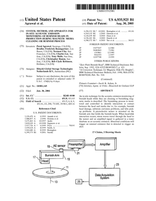
  • 1. (12) United States Patent Agrawal et al. (54) SYSTEM, METHOD, AND APPARATUS FOR IN-SITU ACOUSTIC EMISSION MONITORING OF BURNISH HEADS IN PRODUCTION DURING MAGNETIC MEDIA CLEANING OR BURNISH PROCESS (75) Inventors: Parul Agrawal, Saratoga, CA (US); Bradley Frederick Baumgartner, Los Banos, CA (US); Norman Chu, San Francisco, CA (US); Charles Lee, San Jose, CA (US); Tony Mello, San Jose, CA (US); Christopher Ramm, San Jose, CA (US); Bob Clyde Robinson, Hollister, CA (US) (73) Assignee: Hitachi Global Storage Technologies Netherlands B.V., Amsterdam (NL) ( *) Notice: Subject to any disclaimer, the term of this patent is extended or adjusted under 35 U.S.C. 154(b) by 0 days. (21) Appl. No.: 10/881,145 (22) Filed: Jun.30,2004 (51) Int. CI? ............................................... B24B 49/00 (52) U.S. Cl. ............................................. 451/8; 451/63 (58) Field of Search ................................ 451!5, 6, 8, 9, 451!41, 63, 290; 73/105; 29/90.1, 603.16 (56) References Cited U.S. PATENT DOCUMENTS 5,220,470 A 5,488,857 A 5,675,462 A 5,824,920 A 5,917,726 A * 5,939,624 A 5,942,680 A 6,290,573 B1 17 6/1993 Ananth et a!. 2/1996 Homma et a!. 10/1997 Ayabe 10/1998 Sugimoto et a!. 6/1999 Pryor .......................... 700/95 8/1999 Smith, Jr. 8/1999 Boutaghou 9/2001 Suzuki IIIIII 1111111111111111111111111111111111111111111111111111111111111 US006935925Bl (10) Patent No.: US 6,935,925 Bl (45) Date of Patent: Aug. 30, 2005 6,296,552 B1 * 10/2001 Boutaghou eta!. ........... 451!41 6,503,132 B2 1!2003 Ekstrum et a!. 6,526,639 B2 3/2003 Duan eta!. 6,536,265 B1 3/2003 Hanchi eta!. 6,580,572 B1 * 6/2003 Yao et a!. ..................... 360/25 FOREIGN PATENT DOCUMENTS JP 55077037 6/1980 JP 56083843 7/1981 JP 1310861 12/1989 JP 9016593 1!1997 JP 11037748 2/1999 OTHER PUBLICATIONS "Zero Pitch Burnish Head", IBM Technical Disclosure Bul- letin, Sep. 1992, 92A 62522/R08920217, p. 421. "A Correction Technique for Magnetic Disk Fly Heights", IBM Technical Disclosure Bulletin, Feb. 1990, 90A 63578/ R08870240, Pub. No. 310. (Continued) Primary Examiner-Jacob K. Ackun, Jr. (74) Attorney, Agent, or Firm-Bracewell & Giuliani LLP (57) ABSTRACT An in-situ technique for the acoustic emission monitoring of burnish heads while they are cleaning or burnishing mag- netic media is described. The burnishing process is moni- tored and controlled to identify interaction or contact between the head and media due to, for example, burnish head damage, substrate curvature problems, and lube pick- up problems. A piezoelectric sensor is mounted on the burnish arm that holds the burnish heads. When head-disk interaction occurs, stress waves travel through the head to the sensor and an amplified signal is gathered in a tester database as an acoustic emission. Abnormal conditions will trigger an unusual emission that is detected to trigger an alert. 17 Claims, 3 Drawing Sheets Amplifier Data Acquisition System 23
  • 2. US 6,935,925 Bl Page 2 01HER PUBLICATIONS "Intelligent Burnishing System Using a Cognizant Burnish Head", IBM Technical Disclosure Bulletin, Apr. 1987, 87A 62638/49-240 P300/SA8850248, Pub. No. 276. "Method of Testing Burnishing Magnetic Heads", IBM Technical Disclosure Bulletin, Sep. 1984, 84A 62267/49- 240 P15/GE8820051, p. 2315. * cited by examiner
  • 3. U.S. Patent Aug. 30, 2005 Sheet 1 of 3 17 Burnish Arm FIG. 1 33 FIG. 2 US 6,935,925 Bl Amplifier Data Acquisition System Amplitude Scale 35 23
  • 4. U.S. Patent Aug. 30, 2005 Sheet 2 of 3 US 6,935,925 Bl 0.00 -;r----;--;----;---;--;--;-----:---:---,--:----, -5760 -11519 -17278 -23037 -28796 -34556 -40315 -40074 -51833 ,57592 ..":l-""""'.......""""""........- .................of-r.T"T"T'f-T"''"'T"T""i--T-r...,....,..,"""T"T'~~r-r+"'T'T""rrl 0 2878 5756 ·8634 11512 14390 17268 20146 23024 25902 28780 106 . . ' ' ' ' ' ': I I I I I I I I 95.9 ---------~- --------~--------l-------..-~--------~ --------- --------~---------~-- ------~--------- : : : ! : : : : : 85 8 ---------~---------!-- -------:-------- ..:..-------- ~- ------- --------!---------:..--------~---------. ; : : : : : : : : 75.7 ---------~- --------~- -------~-- -------~- -------i-------- --------~- --------~-- ------~ ---------: I I ' I I I I I 65.6 : ••••••••-~- •••••••-~- ••••••-~ ••••••••-~ ••••••••f•••••••• I ••• •• •• -~ • • • • •• • _. -~•••••• ••1••• •• ••.,... : I I 4 I I I I I j 55 5 ---------~-- ------.:.....---....--~- .................:.....--------~ ----.......... :..........--~- --..-----~-- ------~ --------- . ~ : : : : : : : : : 45.4 =....-·-··--t-·......----~ .............--1---------r--------t-------- ;--------1---------r--------1--------- 35.3 : ---------r---------~-- ------1---------~- -------~- ------- :--------~- --------r--------~---------= : : : : : : : : : !~~ ~::::::::!::::::::r::+I1 r:::::::::::::::::::::::!::::::::r:::::F:::::: 43 I AE output, OD Noise 0 2878 5756 8634 11512 14390 17268 20146 23024 25902 28780 FIG. 3
  • 5. U.S. Patent Aug. 30, 2005 Sheet 3 of 3 US 6,935,925 Bl 51 v 4.0 3.5 3.0 Load ~--Head in Contact /- ... 57 Unload -::s .e- 2.5::s 0 Q) 2.0 en .B ~ 1.5 1.0 0.5 0.0 _oLI!..oM<tl..ll. vss ~ ~ ~ Head -- Flying - (53 1.....dt .,.., .l.JI!I.t .~1o.....,~Jii,,,._.IJIJI ,.,A .1.... ._,_ ....._,,.L- , •• 16.0 6.0 Linear Velocity (m/s) FIG. 4 16.0 ....
  • 6. US 6,935,925 Bl 1 2 response that generally scales with increasing size of the asperity. If the voltage response exceeds a predetermined level, the disk is rejected. One way to reduce such disk defects is to burnish the SYSTEM, METHOD, AND APPARATUS FOR IN-SITU ACOUSTIC EMISSION MONITORING OF BURNISH HEADS IN PRODUCTION DURING MAGNETIC MEDIA CLEANING OR BURNISH PROCESS BACKGROUND OF THE INVENTION 1. Technical Field 5 disks. A thin film disk head burnish process removes the disk surface debris and asperities that are introduced by pre- and post-sputter processes. As stated above, such debris and asperities can reduce disk glide yield and cause other significant disk drive performance problems. The burnish The present invention relates in general to improved processing of disk drive components and, in particular, to an improved system, method, and apparatus for monitoring a condition of a burnish head during a magnetic media clean- ing and/or burnish process. 10 process is utilized on thin film media to remove asperities and loose particles before it can go for glide and magnetic certification tests. Burnishing is typically performed in two steps: a tape burnish process followed by a head burnish. Presently, the burnish heads themselves are not monitored or 2. Description of the Related Art Generally, a data access and storage system consists of one or more storage devices that store data on magnetic or optical storage media. For example, a magnetic storage device is known as a direct access storage device (DASD) or 15 evaluated while in operation. In particular, there have been no attempts to maintain the status of burnish heads at the media glide and magnetic certification testers. Thus, it would be desirable to be able to better understand and evaluate the condition of burnish heads during operation. a hard disk drive (HDD) and includes one or more disks and 20 a disk controller to manage local operations concerning the disks. The hard disks themselves are usually made of aluminum alloy or a mixture of glass and ceramic, and are covered with a magnetic coating. Typically, two or three disks are stacked vertically on a common spindle that is 25 turned by a disk drive motor at several thousand revolutions per minute (rpm). SUMMARY OF THE INVENTION One embodiment of a system, method, and apparatus for in-situ, acoustic emission (AE) monitoring of burnish heads during manufacturing production, while they are cleaning and/or burnishing magnetic media, is described. The present invention effectively monitors and controls the burnishing process to identify interaction or contact between the head and media due to burnish head damage, substrate curvature problems, excessive lubricant pick-up by the slider, etc. This technique utilizes a piezoelectric sensor that is mounted on the burnish arm that holds the burnish heads. Whenever any head-disk interaction occurs, the stress waves travel through the burnish head to the sensor and the amplified signal is A typical HDD also includes an actuator assembly. The actuator moves magnetic read/write heads to the desired location on the rotating disk so as to write information to or 30 read data from that location. Within most HDDs, the mag- netic read/write head is mounted on a slider. A slider generally serves to mechanically support the head and any electrical connections between the head and the rest of the disk drive system. The slider is aerodynamically shaped to glide over moving air in order to maintain a uniform distance from the surface of the rotating disk, thereby preventing the head from undesirably contacting the disk. 35 gathered in the tester database as an AE. This AE information is utilized to serve several objec- tives. If everything is operating normally while a burnish head is flying above the media, there will not be a significant signal and the AE amplitude will be at a noise floor level.Typically, a slider is formed with an aerodynamic pattern of protrusions (air bearing design) on its air bearing surface (ABS) that enables the slider to fly at a constant height close to the disk during operation of the disk drive. A slider is associated with each side of each platter and flies just over the platter's surface. Each slider is mounted on a suspension to form a head gimbal assembly (HGA). The HGA is then attached to a semi-rigid actuator arm that supports the entire head flying unit. Several semi-rigid arms may be combined 40 However, a number of activities may generate an unusual signal that is detected by the system. These abnormal activities include, for example: (a) the head is picking up significant amount of lubricant that affect flyability; (b) the head is damaged; (b) substrate curvature or chamfer prob- to form a single movable unit having either a linear bearing or a rotary pivotal bearing system. 45 lems; and (d) the disk has an unusual amount of contami- nation or mounds. When an event such as these is detected, a system and/or operator is alerted to take action regarding the problem, such as eliminating the damaged burnish head. This could prevent damaging significant number of disks To successfully achieve file performance, the heads must fly steadily at a given fly height over the disk with minimal variations. Since the variations in fly height are dependent 50 and help tremendously in controlling the quality of the disks. on the various sensitivities of the fly height to the process parameters as well as the variability of the parameters, tight process control is mandatory to minimize such variations. 55 Common dominant process parameters affecting fly height include gram load, pivot location, crown and etch depths. The presence of asperities on the surfaces of the disks is a major factor that can have a deleterious effect on the performance of disk drives. Asperities can contact the mag- 60 netic head as it flies at its normal height in a disk drive. For this reason, a glide test is performed on finished disks to detect asperities that might contact the magnetic head during operation. In the test, a special glide head containing a piezoelectric transducer (PZT) is flown over a disk at an 65 altitude or height that is below the normal drive fly height. Glide head contact with an asperity creates a PZT voltage In one embodiment, this in-situ monitoring technique utilizes the AE sensors that detect head disk interaction. The sensors are attached on the block arm that holds the burnish heads. In the event of head disk interaction, the stress wave travels via suspension to the head block and the sensors picks up the signal. In one version, the signal is amplified and monitored with a hardware and acquisition system, such as a preamplifier and an amplifier, and the RMS voltage output value is fed to the data acquisition system. For production monitoring, the signal is picked up at the ID, MD and OD tracks for 1,080 sectors on the media or disk. The disk is identified by converting the cassette num- ber and the slot number into a "Morse code." The intensity of the signal is shown as a stripe next to the disk code and a color scale scheme is used to represent the intensity of the signal. Log files are also generated that contain the cassette number, slot number, glide test information, test time, and
  • 7. US 6,935,925 Bl 3 average value of signals obtained at the ID, MD and OD locations. This method is useful in detecting (a) burnish head interaction with the substrate ski jumps; (b) suspension problems due to wrong alignment and dragging of the heads; and (c) significant lubricant interaction with burnish heads. The present invention can help in determining the radial accessibility of burnish head at the outermost radius of the disk. This method helps optimize the burnish head traverse radius on the disk and avoid its interaction with disk curvature and chamfer. For hybrid burnish sliders, the present invention may be used for spin-down characterization in order to decide the operating point for sweeping as well as burnishing process. For example, hybrid burnish heads may be characterized to decide the operating velocities for sweeping and contact for each burnish head at the manufacturing floor. This feature is analogous to using a bump test for glide heads to decide their operating velocities. 4 a relative magnitude of contact between the burnish head 17 and the magnetic media 11. A data acquisition system 23 receives and processes the signal 21 from the sensor 19. In one embodiment, the sensor 19 comprises a piezoelectric 5 sensor for detecting stress waves traveling from the burnish head 17 through the burnish arm 15 to the sensor 19, and the signal is an acoustic emission (AE). In one embodiment, the signal 21 feeds an RMS voltage output value to the data acquisition system 23, and the data acquisition system 23 10 utilizes a preamplifier 27 and an amplifier 29 to amplify the signal 21. One type of burnish head flies in proximity to the disks and is primarily used for cleaning the particles and loose contamination therefrom. This type may not necessarily aid 15 in burnishing the asperities, such that any type of continuous contact above the noise floor is bad. These heads cannot make a steady contact with the disks. In normal situations, the AE output for these heads would be at the noise floor. The foregoing and other objects and advantages of the present invention will be apparent to those skilled in the art, 20 in view of the following detailed description of the present invention, taken in conjunction with the appended claims and the accompanying drawings. Any output above the noise floor for these heads indicates a problem due to unnecessary head-disk interaction. For example, the system shown in FIG. 1 detects the interaction and signals an alert 25 (e.g., alerts the operator) for preven- tive measures. As shown in FIG. 2, the data acquisition system 23 BRIEF DESCRIPTION OF THE DRAWINGS So that the manner in which the features and advantages 25 distinguishes between normal operating conditions 31 and abnormal operating conditions 33 between the magnetic media 11 and the burnish head 17 in order to detect a problem with the burnish head 17. FIG. 2 represents aof the invention, as well as others which will become apparent are attained and can be understood in more detail, more particular description of the invention briefly summa- 30 rized above may be had by reference to the embodiment thereof which is illustrated in the appended drawings, which drawings form a part of this specification. It is to be noted, however, that the drawings illustrate only an embodiment of the invention and therefore are not to be considered limiting 35 of its scope as the invention may admit to other equally effective embodiments. typical graph obtained from the system of the present invention depicting dozens of magnetic media 11 tested by a single burnish head 17. Each line 35 on the right shows the high value of an acoustic emission (AE) signal at an outer diameter (OD) location on one of the disks. Such a consis- tent and large number of lines 35 indicate problems with the burnish head 17. For example, the sensor 19 may detect damage to the burnish head 17, interaction with radial curvature of the disks near their outer diameters, and accu- mulation of lubricant on the burnish head 17. An alert 25, such as a visual, audible, or electronic signal via computer, to an operator is generated by the system regarding a problem with the burnish head 17. FIG. 1 is a schematic diagram of a burnish head in-situ acoustic emission monitoring system for magnetic media and is constructed in accordance with the present invention; 40 FIG. 2 is an acoustic emissions plot generated by the system of FIG. 1 and is constructed in accordance with the present invention; Comparing FIGS. 2 and 3, the system monitors normal operating conditions 31, which emit a baseline amplitude 41 (lower plot in FIG. 3) at a noise floor level, and abnormalFIG. 3 is an acoustic emissions plot for scanner position- ing generated by the system of FIG. 1 and is constructed in accordance with the present invention; and FIG. 4 is a plot of spin-down and spin-up characteriza- tions of burnish head in the system of FIG. 1 and 1s constructed in accordance with the present invention. DETAILED DESCRIPTION OF THE INVENTION Referring to FIG. 1, one embodiment of a system, method, and apparatus for in-situ, manufacturing production monitoring of burnish heads while they are cleaning and/or burnishing magnetic media is disclosed. The present inven- tion comprises a magnetic media 11 that rotates about an axis 13 and a burnish arm 15 having a burnish head 17 mounted thereto. The burnish arm 15 positions the burnish head 17 adjacent and in proximity to the magnetic media 11, and pivotally moves the burnish head 17 relative to the rotating magnetic media 11 for cleaning or burnishing the magnetic media 11. A sensor 19 is mounted to the burnish arm 15 for detecting physical contact between the burnish head 17 and the magnetic media 11. The sensor emits a signal 21 to identify 45 operating conditions 33, which emit a spike 43 in amplitude that is significantly greater than the noise floor level. The spike 43 happens to coincides at the OD of the magnetic media 11, as shown in the upper plot 45 that depicts the radial position of the burnish head 17 relative to the mag- 50 netic media 11. A second category of head makes steady contact. These heads are used in contact mode to burnish asperities. Hybrid/ contact or hybrid heads are capable to flying as well as making steady contact on the disks. Hence, they could be 55 used for cleaning as well as burnishing small asperities. The velocity of the heads is an important parameter when contact with the disks is established so that the operating points for flying as well as contact mode can be decided when they are used in production. Typically AE output from these heads is 60 low amplitude and steadily increasing as velocity is decreased. If the AE output makes a sudden high amplitude jump then the head is not stable. Referring now to FIG. 4, the present invention also aids in determining the operating velocity for flying 53 and 65 contact mode 51 of hybrid burnish heads. The operating velocity of a hybrid burnish head is characterized by: flying the head 17 in proximity to the magnetic media 11, and then
  • 8. US 6,935,925 Bl 5 reducing a speed of the magnetic media 11 until the sensor 19 detects contact with the magnetic media 11 that exceeds the baseline amplitude 53. The present invention also comprises a method of in-situ monitoring of burnish heads 17 while they are cleaning or 5 burnishing magnetic media 11. The method comprises: providing a magnetic media 11 (FIG. 1) and a burnish arm 15 having one of the burnish heads 17 described herein; rotating a magnetic media 11 about an axis 13; cleaning and/or burnishing the magnetic media 11 with the burnish 10 head 17; detecting contact 43 (FIG. 3) between the burnish head 17 and the magnetic media; identifying a relative magnitude of said contact between the burnish head 17 and the magnetic media 11; and distinguishing between normal and abnormal operating conditions 31, 33 (FIG. 2) between 15 the magnetic media 11 and the burnish head 17 to detect a problem with the burnish head 17. 6 burnish head with disk radial curvature, and accumulation of lubricant on the burnish head. 3. The system of claim 1, wherein the sensor comprises a piezoelectric sensor for detecting stress waves traveling from the burnish head through the burnish arm to the sensor, and the signal is an acoustic emission. 4. The system of claim 1, wherein normal operating conditions emit a baseline amplitude at a noise floor level, and abnormal operating conditions emit a spike in amplitude that is significantly greater than the noise floor level. 5. The system of claim 4, wherein the burnish head is a hybrid/contact burnish head having an operating velocity characterized for proximity flying and steady contact by: flying the burnish head in proximity to the magnetic media, reducing a speed of the magnetic media until the sensor detects contact with the magnetic media that exceeds the baseline amplitude. 6. The system of claim 1, further comprising an alert 20 generated by the system regarding a problem with the burnish head. The method further comprises detecting at least one of damage to the burnish head 17, interaction of burnish head with disk's radial curvature (e.g., determining a farthest OD radius on the disk that the burnish head can reach without interacting with disk chamfer or radial curvature of the disk), and accumulation of lubricant on the burnish head 17. The method may comprise using a piezoelectric sensor 19 for detecting stress waves traveling from the burnish head 17 through the burnish arm 15 to the sensor 19. The signal 21 may be an acoustic emission detected by a data acquisition system 23 to receive and process a signal 21 from the piezoelectric sensor 19. The data acquisition system 23 emits a baseline amplitude 41 at a noise floor level in 30 response to normal operating conditions 31, and a spike 43 in amplitude in response to abnormal operating conditions 33 that is significantly greater than the noise floor level. In addition, the method characterizes an operating veloc- 7. The system of claim 1, wherein the signal feeds an RMS voltage output value to the data acquisition system, and the data acquisition system utilizes a preamplifier and an 25 amplifier to amplify the signal. 8. A method of in-situ monitoring of burnish heads while they are cleaning or burnishing magnetic media, comprising: (a) providing a magnetic media and a burnish arm having a burnish head; (b) rotating a magnetic media about an axis; (c) cleaning or burnishing the magnetic media with the burnish head; ity 51 (FIG. 4) of the burnish head 17 by flying the burnish 35 head 17 in proximity to the magnetic media 11, reducing a speed of the magnetic media 11 until the sensor 19 detects contact with the magnetic media 11. The procedure assists in determining the operating velocity for proximity flying as well as velocity for steady contact for every head used in 40 manufacturing. (d) detecting contact between the burnish head and the magnetic media; (e) identifying a relative magnitude of said contact between the burnish head and the magnetic media; and (f) distinguishing between normal and abnormal operat- ing conditions between the magnetic media and the burnish head to detect a problem with the burnish head. 9. The method of claim 8, wherein step (f) comprises detecting at least one of damage to the burnish head, interaction of burnish head with disk radial curvature at While the invention has been shown or described in only some of its forms, it should be apparent to those skilled in the art that it is not so limited, but is susceptible to various changes without departing from the scope of the invention. What is claimed is: 1. A system for in-situ monitoring of burnish heads while they are cleaning magnetic media, comprising: a magnetic media that rotates about an axis; a burnish arm having a burnish head mounted thereto, the burnish arm positioning the burnish head adjacent the magnetic media and moving the burnish head relative to the rotating magnetic media for cleaning the mag- netic media; a sensor mounted to the burnish arm for detecting contact between the burnish head and the magnetic media, the sensor also emitting a signal to identify a relative magnitude of said contact between the burnish head and the magnetic media; and a data acquisition system for receiving and processing the signal from the sensor to distinguish between normal and abnormal operating conditions between the mag- netic media and the burnish head in order to detect a problem with the burnish head. 2. The system of claim 1, wherein the sensor detects at least one of damage to the burnish head, interaction of outer diameter, and accumulation of lubricant on the burnish 45 head. 10. The method of claim 8, wherein step (d) comprises using a piezoelectric sensor for detecting stress waves traveling from the burnish head through the burnish arm to the sensor, and the signal is an acoustic emission, and steps 50 (e) and (f) comprise using a data acquisition system to receive and process a signal from the piezoelectric sensor. 11. The method of claim 8, further comprising emitting a baseline amplitude at a noise floor level in response to 55 normal operating conditions, and emitting a spike in ampli- tude in response to abnormal operating conditions that is significantly greater than the noise floor level. 12. The method of claim 11, wherein the burnish head is a hybrid/contact burnish head, and further comprising char- 60 acterizing an operating velocity of the hybrid/contact bur- nish head for proximity flying and steady contact by: flying the burnish head in proximity to the magnetic media, reduc- ing a speed of the magnetic media until the sensor detects contact with the magnetic media that exceeds the baseline 65 amplitude. 13. The method of claim 8, further comprising generating an alert regarding a problem with the burnish head.
  • 9. US 6,935,925 Bl 7 14. The method of claim 8, further comprising feeding an RMS voltage output value to the data acquisition system, and using a preamplifier and an amplifier to amplify a signal thereof. 15. The method of claim 8, further comprising determin- 5 ing a farthest point on the disk that the burnish head can reach without interacting with disk chamfer or radial cur- vature of the disk. 16. An apparatus for in-situ monitoring of burnish heads while they are cleaning or burnishing magnetic media, 10 comprising: a burnish arm adapted to support a burnish head thereon for positioning the burnish head adjacent a magnetic media and cleaning or burnishing the magnetic media; 8 a data acquisition system for receiving and processing the signal from the sensor to distinguish between normal and abnormal operating conditions between the mag- netic media and the burnish head in order to detect a problem with the burnish head, wherein normal oper- ating conditions emit a baseline amplitude at a noise floor level, and abnormal operating conditions emit a spike in amplitude that is significantly greater than the noise floor level, the data acquisition system being adapted to generate an alert regarding a problem with the burnish head; and wherein the signal feeds an RMS voltage output value to the data acquisition system, and the data acquisition system utilizes a preamplifier and an amplifier to amplify the signal. 17. The apparatus of claim 16, wherein the sensor is adapted to detect at least one of damage to the burnish head, problems with the interaction of the burnish head with disk radial curvature, and accumulation of lubricant on the bur- a sensor mounted to the burnish arm adapted to detect 15 contact between the burnish head and the magnetic media, the sensor emitting a signal to identify a relative magnitude of said contact between the burnish head and the magnetic media, and the sensor comprising a piezoelectric sensor for detecting stress waves traveling from the burnish head through the burnish arm to the sensor, and the signal is an acoustic emission; 20 nish head. * * * * *