Process Signal Isolated Transmitters, 4-20 ma
•
0 gostou•965 visualizações

4-20mA process current inputs are isolated and transmitted as 4-20mA output signals. Each channel operates independently and is isolated from the others to prevent interaction between channels.

Recomendados
Recomendados
Mais conteúdo relacionado
Mais procurados
Mais procurados (20)
Destaque
Destaque (16)
Semelhante a Process Signal Isolated Transmitters, 4-20 ma
Semelhante a Process Signal Isolated Transmitters, 4-20 ma (20)
Último
Último (20)
Process Signal Isolated Transmitters, 4-20 ma
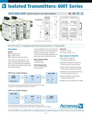
- 1. 651T, 652T, 653T Multi-Channel, Two-Wire Isolators Description Models 651T: Single I/O channel 652T: Dual I/O channel 653T: Single input, dual output (splitter) These units receive 4-20mA process current inputs and provide isolated 4-20mA output signals. Each channel operates independently and is isolated from the others to prevent inter- action between channels. For easy troubleshooting, each unit has LEDs and diagnostic test points. Power LEDs help identify output open loop conditions. The precision 10 ohm sense resistor enables monitoring of the output signal without disturbing field wiring. Input / Output Ranges 4 to 20mA DC input 4 to 20mA DC output Power Requirement 12 to 36V DC (loop-powered) Two-wire transmitter Approvals CE marked. UL, cUL listed Class I, Division 2, Groups A, B, C, D. Key Features & Benefits ■ Two channels in a single unit saves space and reduces costs. ■ Signal splitter model (653T) provides two identical outputs from one input signal. ■ Galvanic isolation eliminates ground loops, reduces noise, and blocks transient signals. ■ Independent channels prevent signal interac- tion and offer spares for later use. ■ Power LEDs provide a visual indication of operational process loops. ■ Excellent accuracy and stability ensure reliable DC current input ◆ Single/dual-channel DC-powered isolators ◆ Signal splitter Acromag DIN EN 50022, 35mm "T" RAIL DIN MOUNTING (59.4) 2.34 CL (95.3) 3.75 ZERO SPAN R 1.05 (26.7) NOTE: ALL DIMENSION ARE IN INCHES (MILLIMETERS) (107.1) 4.215 (99.1) 3.90 4.35 (110.5) CHAN 1 PWR CH1 IN CH1 OUT IN- IN+ OUT- SNS OUT+ 11 12 13 14 15 16 TB1 CH2 IN CH2 OUT IN- IN+ OUT- SNS OUT+ 21 22 23 24 25 26 TB2 TB1 ZERO SPAN CHAN 2 PWR INPUT CH1 OUT IN- IN+ OUT- SNS OUT+ 11 12 13 14 15 16 TB1 CH2 OUT OUT- SNS OUT+ 21 22 23 24 25 26 TB2 Model 652T-0600 Model 651T-0600 Model 652T-0600 Model 653T-0600 TB1 TB2 Model 653T-0600 INPUT OUT PLC / DCS IN + – – + RL 4-20mA 24V DC 4-20mA 4-20mA Source 651T+ – Field Device – + Single channel shown. Dual channel units are available. Note: 670T series transmitters are for output resistive loads only (sources current). For more information on the 670T Transmitter, refer to Page 14. Application notes are on Page 16. Note: 650T series transmitters are for two-wire transmitter interfaces (sinks current). For application notes using 650T Transmitters, refer to Page 16. 650T Series Isolation Diagram OUTOUT PLC / DCS IN – + RL 4-20mA + – + – 671T Single channel shown. Quad channel units are available. 4-20mA Field Device 670T Series Isolation Diagram Isolated Transmitters: 600T Series Tel: 248-295-0880 ■ Fax: 248-624-9234 ■ sales@acromag.com ■ www.acromag.com ■ 30765 S Wixom Rd, Wixom, MI 48393 USA – 6 –
- 2. Performance Specifications Reference Test Conditions Input/Output current: 4 to 20mA; output load 500 ohms; 77°F (25°C). Input range 4 to 20mA input (each channel). Input burden Voltage drop (651T, 652T): Less than 1.5V, typical (75 ohm equivalent). Voltage drop (653T): Less than 3.0V, typical (150 ohm equivalent). Output range 4-20mA DC output (each channel). Rl = (Psupply-12V) / 0.02 Output compliance Psupply = 12V + (0.02 x Rload) Output limiting Outputs are limited to 36mA. Output ripple Less than ±0.1% of the maximum output span. Accuracy ±0.1% of output span. Error includes the combined effects of isolator repeatability, hysteresis, terminal point linearity and adjustment resolution. Ambient temperature effect Less than ±0.006% of input span per °F (±0.01% per °C) over the ambient temperature range for reference test conditions. This specification includes the com- bined effects of zero and span over temperature. Calibration Two 15-turn potentiometers (zero and span) per channel, accessible from front of the unit. Bandwidth -3dB at 45Hz, typical. Response time For a step input, the output reaches 98% of output span in 15mS, typical. Noise rejection Common mode: 100dB at 60Hz, typical. Normal mode: -5dB at 60Hz, 100 ohm source, typical. Diagnostics LED power indicator: Off for output open loop detec- tion, power, or load compliance problem. Field test points: An internal 10 ohm sense resistor provides test points for monitoring the output signal current during field maintenance. ◆ Environmental Ambient Temperature Operating: -25 to 70°C (-13 to 158F). Storage: -40 to 85°C (-40 to 185°F). Relative Humidity 5 to 95%. Power Requirement 12 to 50V DC for each output channel. Isolation Inputs, outputs, and individual channels are isolated from each other for common-mode voltages up to 250V AC, or 354V DC off ground, on a continuous basis (will withstand 1500V AC dielectric strength test for one minute without breakdown). Radiated Field Immunity (RFI) Complies with EN61000-4-3 Level 3 (10V/m, 30 to 1000MHz) and European Norm EN50082-1. Electromagnetic Field Immunity (EMI) Less than ±0.25% of output span effect under the influence of electromagnetic fields from switching solenoids, commutator motors, and drill motors. Surge Immunity Complies with EN61000-4-5 Level 3 (2KV) and European Norm EN50082-1. Electrical Fast Transient (EFT) Complies with EN61000-4-4 Level 3 (2KV) and European Norm EN50082-1. Electrostatic Discharge (ESD) Complies with EN61000-4-2 Level 3 (8KV air, 4KV direct to the enclosure port) and European Norm EN50082-1. Radiated Emissions Meets or exceeds European Norm EN50081-1 for Class B equipment. Approvals CE marked, UL & cUL listed. Hazardous Locations: Class I: Div. 2; Groups A, B, C, D ◆ Physical Enclosure Case: Self-extinguishing NYLON type 6.6 polyamide thermoplastic UL94 V-2 NEMA Type 1 enclosure. Connectors (Removable Terminal Blocks) Wire Range: AWG #14-22 (AWG #12 stranded only). Printed Circuit Boards Military grade FR-4 epoxy glass circuit board. Dimensions 1.05W x 4.68H x 4.35D inches. 26.7W x 95.3H x 110.5D millimeters. Shipping Weight 1 pound (0.45 Kg) packed. Ordering Information ◆ Models 651T-0600 Single channel 2-wire transmitter 652T-0600 Dual channel 2-wire transmitter 653T-0600 Single input with dual isolated output transmitter ◆ Accessories (see Page 21) PS5R-SD24 Power supply (24V DC, 2.5A). TBK-B01 Optional terminal block kit, barrier strip style, 2 pcs. TBK-S01 Optional terminal block kit, spring clamp style, 2 pcs. DIN RAIL 3.0 DIN RAIL 16.7 DIN rail strip, Type T, 3 inches (75mm) or 16.7 inches (425mm) 20RM-16-DIN 19” rack-mount kit with DIN rail. Holds sixteen 650T transmitters. Optional terminal blocks: barrier strip (left) and spring clamp (right). Cage clamp terminal is standard. Isolated Transmitters: 600T Series Tel: 248-295-0880 ■ Fax: 248-624-9234 ■ sales@acromag.com ■ www.acromag.com ■ 30765 S Wixom Rd, Wixom, MI 48393 USA – 7 –
- 3. Barrier Strip Terminal Blocks* Spring Clamp Terminal Blocks* Ordering Information * I/O modules ship with cage clamp terminal blocks. Terminal block kits are for replacement purposes. See I/O module information for compatibility Din-Rail Mounting For your convenience, Acromag offers several mounting accessories to simplify your system installation. Our 19” rack-mount kit provides a clean solution for mounting your I/O modules and a power supply. Or you can buy precut DIN rail strips for mounting on any flat surface. Ordering Information 20RM-16-DIN 19” rack-mount kit with DIN rail. DIN RAIL 3.0 DIN RAIL 16.7 DIN rail strip, Type T, 3 inches (75mm) or 16.7 inches (425mm) This external sensor measures a 0-20A AC signal and provides a DC mA output for an Ethernet input module. It enables remote mounting of the I/O module for safe monitoring of the AC signal. Ordering Information 5020-350 AC current sensor 60W Universal Slimline Power Supply Input Power Requirement 85 to 264V AC or 100 to 370V DC Output 24V DC, 2.5A (60W) Ordering Information PS5R-SD24 Universal 60W power supply Visit www.acromag.com for additional models and more information. Ordering Information 5035-355 Ethernet straight cable, CAT5, 3 feet long, shielded 5035-360 Ethernet crossover cable, CAT5E, 5 feet long, shielded ◆ Power Supplies ◆ AC Current Sensor ◆ Mounting Hardware◆ Terminal Blocks Accessories RJ45 RJ45 CONNECTS 900EN-S005 SWITCH TO 9XXEN ETHERNET I/O MODULE 3 Feet LONG STRAIGHT CAT5 CABLE Barrier Strip TBK-B01 Terminal block kit, two 6-position pieces TBK-B02 Terminal block kit, four 6-position pieces TBK-B03 Terminal block kit, one 3-position and three 6-position pieces Spring Clamp TBK-S01 Terminal block kit, two 6-position pieces TBK-S02 Terminal block kit, four 6-position pieces TBK-S03 Terminal block kit, one 3-position and three 6-position pieces Wire range: AWG #12-26 3-position: L = 0.66 inches (16.9 mm) 6-position: L = 1.26 inches (32.3 mm) ◆ Cables Isolated Transmitters: 600T Series Tel: 248-295-0880 ■ Fax: 248-624-9234 ■ sales@acromag.com ■ www.acromag.com ■ 30765 S Wixom Rd, Wixom, MI 48393 USA – 21 –