
Recomendados
Mais conteúdo relacionado
Mais procurados
Mais procurados (20)
Destaque
Destaque (20)
Semelhante a Ch 7 design of rcc footing
Semelhante a Ch 7 design of rcc footing (20)
Último
Último (20)
Ch 7 design of rcc footing
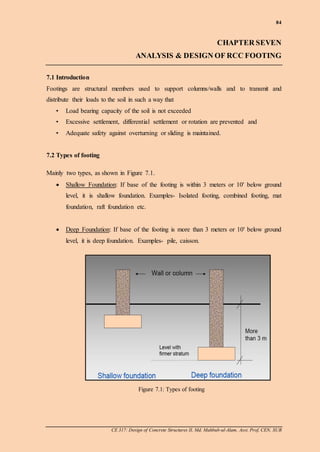
- 1. 84 CE 317: Design of Concrete Structures II, Md. Mahbub-ul-Alam, Asst. Prof, CEN, SUB CHAPTER SEVEN ANALYSIS & DESIGN OF RCC FOOTING 7.1 Introduction Footings are structural members used to support columns/walls and to transmit and distribute their loads to the soil in such a way that • Load bearing capacity of the soil is not exceeded • Excessive settlement, differential settlement or rotation are prevented and • Adequate safety against overturning or sliding is maintained. 7.2 Types of footing Mainly two types, as shown in Figure 7.1. Shallow Foundation: If base of the footing is within 3 meters or 10' below ground level, it is shallow foundation. Examples- Isolated footing, combined footing, mat foundation, raft foundation etc. Deep Foundation: If base of the footing is more than 3 meters or 10' below ground level, it is deep foundation. Examples- pile, caisson. Figure 7.1: Types of footing
- 2. 85 CE 317: Design of Concrete Structures II, Md. Mahbub-ul-Alam, Asst. Prof, CEN, SUB 7.3 Types of Shallow foundation 1) Isolated/Single footing They are used to support single columns, as shown in right figure. This is one of the most economical types of footings and is used when columns are spaced at relatively long distances. They are divided into two categories: i. Square Footing ii. Rectangular Footing 2) Combined footing Such footings usually support two columns, or three columns not in a row, as shown in Figure 7.2 below. Combined footings are used when two columns are so close that single footings cannot be used or when one column is located at or near a property line. Figure 7.2: Combined footing
- 3. 86 CE 317: Design of Concrete Structures II, Md. Mahbub-ul-Alam, Asst. Prof, CEN, SUB 3) Cantilever or strap footing It consists of two single footings connected with a beam or a strap and support two single columns, as shown in right figure. This type replaces a combined footing and is more economical. 4) Continuous footing They support a row of three or more columns, as shown in right figure. They have limited width and continue under all columns. 5) Raft or mat foundation It consists of one footing usually placed under the entire building area, as shown in right figure. They are used, when soil bearing capacity is low, column loads are heavy, single footings cannot be used, piles are not used and differential settlement must be reduced.
- 4. 87 CE 317: Design of Concrete Structures II, Md. Mahbub-ul-Alam, Asst. Prof, CEN, SUB (b) Figure 7.3: (a) Assumed uniform soil pr. distribution (b) Cohesionless soil pr. distribution (c) Cohesive soil pr. distribution (c) (a) 7.4 Soil pressure distribution under footing When the column load is applied on the centroid of the footing, a uniform pressure is assumed to develop on the soil surface below the footing area, as shown in Figure 7.3(a). However the actual distribution of the soil is not uniform, as shown in Figures 7.3(b) and (c). It depends on many factors especially the composition of the soil and degree of flexibility of the footing. 7.5 Design Considerations of footing Minimum Footing thickness is 6.0". Concrete cover is 3.0". In footing, long direction bars are placed below the short direction bars. Average effective depth in both directions, d = h – clear cover = h – 4.0". Effective depth in short direction, ds = h - 4.5″. Effective depth in long direction, dl = h - 3.5″. #5~#11 bars are usually used as main bars in footing.
- 5. 88 CE 317: Design of Concrete Structures II, Md. Mahbub-ul-Alam, Asst. Prof, CEN, SUB Effective soil pressure (qeff) & net soil pressure (qn) Based on Figure 7.4, qeff and qn will be determined as below. Weight of backfill soil, Ws = Unit wt. of soil x Depth of backfill soil = ss hw Weight of base concrete, Wc = Unit wt. of conc. x Depth of base conc. = cc hw Effective upward soil pressure, qeff = Allowable soil pressure - Wt. of backfill - Wt. of base = csa WWq Area of footing = effeff q LLDL q P Provided area of footing, Ag = Width of footing, B X Length of footing, L Net soil pressure, qn gg u A LLDL A P 162.1 Figure 7.4: Loads acting on footing Column width, c Pedestal column, (c+3") Ground level Depth of base, hc Depth of backfill, hs Depth of footing, Df Wt. of backfill Ws Wt. of backfill Ws Wt. of base, Wc Allowable soil pressure, qa Regular column
- 6. 89 CE 317: Design of Concrete Structures II, Md. Mahbub-ul-Alam, Asst. Prof, CEN, SUB Critical sections in Footing As shown in Figure 7.5, there three critical sections for RCC footing: i. Critical section for beam shear or one way shear which is checked at a distance d from the faces of the pedestal column in both directions. ii. Critical section for punching shear or two way shear which is checked at a distance d/2 from all faces of pedestal column. iii. Critical section for moment which is checked at faces of pedestal column in both directions. Dimension of the Footing For economic purposes, the footing base is tapered at both sides as shown in right figure. Figure 7.5: Critical sections for footing 2/3h hh 15 ʹʹ h Main bars of the footing Column bars
- 7. 90 CE 317: Design of Concrete Structures II, Md. Mahbub-ul-Alam, Asst. Prof, CEN, SUB 7.6 DesignProblem (Isolated Footing) A reinforced concrete footing base of a low rise residential building is to be constructed 5′ below ground level. The allowable soil pressure obtained from soil test report is allq = 4.5 ksf. The footing supports a 12″x14″ RCC column which is reinforced by 4#7 bars. Including self-weight, footing has to carry the following loads: Total un-factored dead load, DL = 307.56 k Total un-factored live load, LL = 51.2 k The material properties are as below: fy = 60,000 psi f’c= 4,000 psi Unit weight of soil, sw = 100 pcf Unit weight of concrete, cw = 150 pcf Answer the followings: a) Determine the size and area of the footing b) Check effective depth, ‘d’ c) Calculate reinforcement, ‘Ast’ in both directions d) Check for hook requirement of the main bars in both directions e) Check for dowel bar and its hook requirement Square footing Given data: Depth of base below G.L. = 5′-0″ Unit weight of soil, sw = 100 pcf Allowable soil pressure, allq = 4.5 ksf fy = 60,000 psi f’c= 4,000 psi Size of the column =12″x14″ Step-1: Load calculation Total un-factored load, P = DL+LL = 307.56 + 51.2 = 358.8 k Total factored load, uP = 1.2DL+1.6LL = 1.2*307.11 + 1.6*51.2 = 450.5 k
- 8. 91 CE 317: Design of Concrete Structures II, Md. Mahbub-ul-Alam, Asst. Prof, CEN, SUB Step-2 Determination of the footing size Let the depth of footing base, h = 22″=1.83 ft. Provided avg. effective depth in both directions, d = h – clear cover = 22.0 – 4.0 = 18.0″ Weight of soil, sW = 66.316 12 22 5*100hws lb/ft2 Weight of base concrete, cW = 50.27483.1*150hwc lb/ft2 Effective upward soil pressure, qeff = csa WWq = 4500-316.66-274.50 = 3908.84 lb/ft2 = 3.909 k/ft2 Area of footing = 7.91 909.3 8.358 effq LLDL ft2 Size of footing = 10′x 10′ Provided area of footing, Ag = 100 ft2 Net soil pressure, ksf A P q g u n 5.4 100 5.450 Step-3: Check for‘d’ Check by punching (two-way) shear Punching shear is checked at a distance d/2 from all faces of column as shown in figure. The pedestal column size = 15″x17″ "136)1817(2)1815(2)(2)(2 210 dcdcb "00.351817 "00.331815 2 1 dc dc Calculating the punching shear force, uV = dcdcqP nu 21 = 450.5-4.5* 12 35 * 12 0.33 = 414.4 k For preventing punching failure, Concrete shear strength = punching shear force uc Vdbfor 0'4, or, "1.16 136*000,4*4*75.0 1000*4.414 '4 0 bf V d c u The required "00.81"1.16 d , so ok.
- 9. 92 CE 317: Design of Concrete Structures II, Md. Mahbub-ul-Alam, Asst. Prof, CEN, SUB x x Check by beam (one-way) shear Beam shear is checked at a distance d from any face of the column along the longer side of footing as shown in figure. The beam shear force, Vu = qn*b* x For preventing one-way shear failure, Concrete shear strength = beam shear force The required, "0.81"4.11 d , so ok. Step-4: Calculation of the main steel (both directions) Moment will be taken at the face of the column for calculating main steel as shown in figure. # Calculation of uM = 435.6 k-ft # Calculation of 0026.0 18)1210(490.085.0 126.4352 11 60 485.0 85.0 2 11 85.0 22' ' xxxxx xxx bdf M f f c u y c k d cL bqVor nu 4.129 12 0.18 12*2 15 2 10 *10*5.4 22 1 ''4.11 )12*10(*000,4*75.0*2 1000*4.129 , 4.129'2 dor bdforVV cuc 10* 2 40.4 *40.4*5.4 * 2 ** b x xqM nu ft cL x 40.4 2 12 15 2 10 22 1
- 10. 93 CE 317: Design of Concrete Structures II, Md. Mahbub-ul-Alam, Asst. Prof, CEN, SUB l L c Cover # Required reinforcement in both directions (1) 62.50.18*)12*10(*0026.0 bdAs in2 # The minimum amount of steel for shrinkage and flexural are (2) 75.422*)12*10(*0018.00018.0 bhAs in2 (3) 2.7 000,60 0.18*)12*10(*200200 y s f bd A in2 From (1~3), selected 2.7sA in2 # Use #6 bar and the number of bars needed, 174.16 44.0 2.7 b s A A n nos. # Spacing between bars, ''0.7"13.7 117 3*212*10 1 cov*2 n erL S c/c Use 17#6 @ 7.0″ c/c both ways. Step-5: Check for hook requirement for the main bars The development length dl for #6 bars of the footing required for proper bonding, "6.35 000,4*20 8 6 *000,60 '20 c by d f df l The available length beyond column face as shown in figure. All of the main bars should be provided without hooks in both directions. Step-6: Check for dowel bar and its hook requirement Minimum area of dowels required = 0.005x Pedestal column area = 0.005*15*17 = 1.28 in2 Extend 4#7 column bars into the footing acting as dowel and provided area = 4x0.60 = 2.40 in2 >1.28 in2 so ok. .,"6.35"5.49 2 15 3 2 12*10 2 cov 2 okl c er L l d
- 11. 94 CE 317: Design of Concrete Structures II, Md. Mahbub-ul-Alam, Asst. Prof, CEN, SUB lh The development length of the dowels #7 bar in compression is 1. "6.16 000,4 000,60* 8 7 *02.0 ' 02.0 c yb d f fd l 2. "75.15000,60* 8 7 *0003.00003.0 ybd fdl 3. "8dl "17"6.16 dl As shown in figure, available length = diabarsmainerh *2cov = 22-3-[ ] 8 6 8 6 = 17.5" > "17dl , so ok. No hook is required at the free ends of the column bars but will be bend at 90° and extend up to a length required for binding of column bars with footing bars. A detail of the reinforcement arrangement is shown in Figure 7.6. h = 22ʹʹh = 22ʹʹ 15ʹʹ L = 10ʹ 17#6 @7ʹʹ both ways h = 22ʹʹ 4#7 column bars Figure 7.6: Details of reinforcement arrangement in square RCC footing
- 12. 95 CE 317: Design of Concrete Structures II, Md. Mahbub-ul-Alam, Asst. Prof, CEN, SUB Rectangular footing Given data: Depth of base below G.L. = 5′-0″ Unit weight of soil, sw = 100 pcf Allowable soil pressure, allq = 4.5 ksf fy = 60,000 psi f’c= 4,000 psi Size of the column =12″x14″ Step-1: Load calculation Total un-factored load, P = DL+LL = 307.56 + 51.2 = 358.8 k Total factored load, uP = 1.2DL+1.6LL = 1.2*307.11 + 1.6*51.2 = 450.5 k Step-2 Determination of the footing size Let the depth of footing base, h = 22″=1.83 ft. Average effective depth in both directions, d = h – clear cover = 22.0 – 4.0 = 18.0″ Provided effective depth in short direction, ds = h - 4.5 = 22.0 – 4.5 = 17.5″ Provided effective depth in long direction, dl = h - 3.5 = 22.0 – 3.5 = 18.5″ Weight of soil, sW = 66.316 12 22 5*100hws lb/ft2 Weight of base concrete, cW = 50.27483.1*150hwc lb/ft2 Effective upward soil pressure, qeff = csa WWq = 4500-316.66-274.50 = 3908.84 lb/ft2 = 3.909 k/ft2 Area of footing = 7.91 909.3 8.358 effq LLDL ft2 Size of footing = 8.0′x 11.5′ Provided area of footing, Ag = 92 ft2 Net soil pressure, ksf A P q g u n 9.4 92 5.450
- 13. 96 CE 317: Design of Concrete Structures II, Md. Mahbub-ul-Alam, Asst. Prof, CEN, SUB x Step-3: Check for‘d’ Check by punching (two-way) shear Punching shear is checked at a distance d/2 from all faces of column as shown in figure. The pedestal column size = 15″x17″ "136)1817(2)1815(2)(2)(2 210 dcdcb "00.351817 "00.331815 2 1 dc dc Calculating the punching shear force, uV = dcdcqP nu 21 = 450.5-4.9* 12 35 * 12 0.33 = 411.2 k For preventing punching failure, concrete shear strength = punching shear force uc Vdbfor 0'4, or, "94.15 136*000,4*4*75.0 1000*2.411 '4 0 bf V d c u The required "50.81"94.15 d , so ok Check by beam (one-way) shear Beam shear is checked at a distance d from any face of the column along the longer side of footing as shown in figure. The beam shear force, Vu = qn*b* x For preventing one-way shear failure, Concrete shear strength = beam shear force The required, "50.81"24.15 d , so ok. k d cL bqVor 83.138 12 0.18 12*2 17 2 5.11 *8*9.4 22 1 nu ''24.15 )12*8(*000,4*75.0*2 1000*3.138 , 3.138'2 dor bdforVV cuc
- 14. 97 CE 317: Design of Concrete Structures II, Md. Mahbub-ul-Alam, Asst. Prof, CEN, SUB x Step-4: Calculation of the main steel A. Long direction reinforcement Moment will be taken at the face of the column for calculating main steel as shown in figure. # Calculation of Mu 9.4 2 12 17 2 5.11 22 cL x ft = 470.6 k-ft # Calculation of 0033.0 5.18)128(490.085.0 126.4702 11 60 485.0 85.0 2 11 85.0 22' ' xxxxx xxx bdf M f f c u y c # Required reinforcement in long direction, (1) 82.55.18*)12*8(*0033.0 bdAs in2 # The minimum amount of steel for shrinkage and flexural are (2) 80.322*)12*8(*0018.00018.0 bhAs in2 (3) 92.5 000,60 5.18*)12*8(*200200 y s f bd A in2 From (1~3), selected 92.5sA in2 # Use #7 bar and the number of bars needed, 1087.9 60.0 92.5 b s A A n nos. # Spacing between bars, "10 9 90 110 3*212*8 1 cov*2 n erb S c/c Use 10#7@ 10.0″ c/c in long direction. 8* 2 9.4 *9.4*9.4 * 2 ** b x xqM nu
- 15. 98 CE 317: Design of Concrete Structures II, Md. Mahbub-ul-Alam, Asst. Prof, CEN, SUB l L c Cover Check for hook requirement: # The development length dl for #7 bars of the footing in long direction, "2.33 000,4*25 875.0*000,60 '25 c by d f df l The available length beyond column face as shown in figure. So ok and no hook is required. B. Short direction reinforcement Moment will be taken at the face of the column for calculating main steel as shown in figure. # Calculation of Mu 38.3 2 12 15 2 8 22 cb y ft 5.11* 2 38.3 *38.3*9.4 * 2 ** L y yqM nu = 321.9 k-ft # Calculation of 0017.0 5.17)125.11(490.085.0 129.3212 11 60 485.0 85.0 2 11 85.0 22' ' xxxxx xxx bdf M f f c u y c # Required reinforcement in short direction, (1) 15.45.17*)12*5.11(*0017.0 bdAs in2 "2.33"5.57 2 17 3 2 12*5.11 2 cov 2 dl c er L l y
- 16. 99 CE 317: Design of Concrete Structures II, Md. Mahbub-ul-Alam, Asst. Prof, CEN, SUB # The minimum amount of steel for shrinkage and flexural are (2) 5.522*)12*5.11(*0018.00018.0 bhAs in2 (3) 05.8 000,60 5.17*)12*5.11(*200200 y s f bd A in2 From (1~3), selected 05.8sA in2 # Use #6 bar, compute the number of bars needed 193.18 44.0 05.8 b s A A n nos. Arrangement of steel: Maximum number of the total 19 nos. reinforcing bars will be placed in band width. *Band width size It is taken as equal to the footing width as shown in figure. Bandwidth = width of footing So, b = 8′ *Steel in band width Where, 144.1 2 19 widthbandinSteel Or, no. of required reinforcing bars in band width = 15.57 16 nos. *Spacing for Band width S = "0.64.6 116 12*8 1-n widthBand *Remaining length at each side of band width = ½ (L- band width – 2*concrete cover) = ½ (11.5'-8'-2*3) = 1.5' Excess reinforcing bars = 19-16 = 3 nos. Place 2#6 at the mid of 1.5' i.e. 9 c/c at both sides of the band width. 44.1 8 5.11 footingofsideshort footingofsidelong 1 2 steelTotal widthbandinSteel
- 17. 100 CE 317: Design of Concrete Structures II, Md. Mahbub-ul-Alam, Asst. Prof, CEN, SUB lh Check for hook requirement: The development length dl for #6 bars of the footing in short direction for proper bonding "6.35 000,4*20 75.0*000,60 '20 c by d f df l The available length beyond column face as shown in figure. .,"6.35"5.37 2 15 3 2 12*8 2 cov 2 oksol c er L l d All of the main bars should be provided without hooks in short direction. Step-5: Check for dowel bar and its hook requirement Minimum area of dowels required = 0.005x Pedestal column area = 0.005*15*17 = 1.28 in2 Extend 4#7 column bars into the footing acting as dowel and provided area = 4x0.60 = 2.40 in2 >1.28 in2 so ok. The development length of the dowels #7 bar in compression is 1. "6.16 000,4 000,60* 8 7 *02.0 ' 02.0 c yb d f fd l 2. "75.15000,60* 8 7 *0003.00003.0 ybd fdl 3. "8dl "17"6.16 dl As shown in figure, available length = diabarsmainerh *2cov = 22-3-[ ] 8 7 8 6 = 17.4" > "17dl , so ok. No hook is required at the free ends of the column bars but will be bend at 90° and extend up to a length required for binding of column bars with footing bars. l L c Cover
- 18. 101 CE 317: Design of Concrete Structures II, Md. Mahbub-ul-Alam, Asst. Prof, CEN, SUB A detail of the reinforcement arrangement is shown in Figure 7.7. 16 # 6 @ 6ʹʹ h = 22ʹʹ L = 11.5ʹ 2#6 @ 9ʹʹ h = 22ʹʹ 15ʹʹ h = 22ʹʹ Figure 7.7: Details of reinforcement arrangement in rectangular RCC footing 10 #7 @10.0"Band width = 8ʹ 4 # 7 column bars
- 19. 102 CE 317: Design of Concrete Structures II, Md. Mahbub-ul-Alam, Asst. Prof, CEN, SUB 7.7 DesignProblem (Combined Footing) Design a combined footing to support two square columns, as shown in figure below. The exterior pedestal column (I) has a section 16"x16", which carries DL of 180 k and a LL of 120 k. The interior pedestal column (II) has a section of 20"x20", which carries a DL of 250 k and a LL of 140 k. The base of the footing is 5' below final grade and allowable soil pressure is 5 k/ft2. Use f’c = 4 ksi and fy = 60 ksi. The external column is located 2' from the property line. Solution Step-1: Load calculation Un-factored load, Column I: P = DL+LL = 180 + 120 = 300 k Column II: P = DL+LL = 250 + 140 = 390 k Total un-factored loads for both columns = 300+390 = 690 k Factored load, Column I: Pu = 1.2DL+1.6LL= 1.2*180+1.6*120 = 408 k Column II: Pu = 1.2DL+1.6LL= 1.2*250+1.6*140 = 524 k Total factored loads for both columns = 408+524 = 932 k Step-2: Determination of the centroid of the footing I II a = 4' x Col. IICol. I 16'2' P = 300 k Pu= 408 k P = 390 k Pu= 524 kResultant R
- 20. 103 CE 317: Design of Concrete Structures II, Md. Mahbub-ul-Alam, Asst. Prof, CEN, SUB Consider the resultant of the all un-factored loads acts at distance ‘x’ from the centerline of ‘Column I’. Extend the footing up to the property line of column I, half footing length = 9' + 2' = 11' So the length of the footing = 2 x 11 = 22'. The length, a = 22-(2+16) = 4'. Step-3: Determination of the footing size Let the depth of footing base, h = 36″=3'. Average effective depth in both directions, d = h – clear cover = 36.0 – 4.0 = 32.0″ Provided effective depth in short direction, ds = h - 4.5 = 36.0 – 4.5 = 32.5″ Provided effective depth in long direction, dl = h - 3.5 = 36.0 – 3.5 = 33.5″ Weight of soil, sW = 200 12 36 5*100 hws lb/ft2 Weight of base concrete, cW = 4503*150 hwc lb/ft2 Effective upward soil pressure, qeff = csa WWq = 5,000-200-450 = 4,350 lb/ft2 = 4.35 k/ft2 Area of footing = 62.158 35.4 690 effq LLDL ft2 Length of the footing, L = 22' Hence, width of the footing, B = '50.721.7 22 62.158 Size of footing = 7.5′x 22.0′ Provided area of footing, Ag = 165 ft2 Net soil pressure, ksf A P q g u n 65.5 165 932 ft.9Useft. 300xft390x16ft F Fx x i ii 04.9 390300 0
- 21. 104 CE 317: Design of Concrete Structures II, Md. Mahbub-ul-Alam, Asst. Prof, CEN, SUB Step-4: SFD and BMD 1.33' 1.33' 14.5' 1.67' 3.17' SFD BMD 20"x20"16"x16" 4' Col. IICol. I 16'2' Pu = 408 k Pu = 524 k qu= 5.65 ksf = 5.65x7.5= 42.38 k/ft -323.38 k 319.38 k 56.37 k 84.62 k -295.13 k -134 k -169.3 k 354.7 k 212.17 k-ft 338.6 k-ft -1149.1 k-ft 84.62 k-ft 37.5 k-ft
- 22. 105 CE 317: Design of Concrete Structures II, Md. Mahbub-ul-Alam, Asst. Prof, CEN, SUB Step-5: Check for‘d’ Check by punching (two-way) shear Punching shear will be checked at a distance d/2 from all faces of the loaded column II as shown in figure. "208)3220(4)(40 dcb "00.523220 dc Calculating the punching shear force, uV = dcdcqP nu = 524- 5.65* 12 52 * 12 52 = 417.91 k For preventing punching failure, concrete shear strength = punching shear force uc Vdbfor 0'4, or, "96.11 208*000,4*4*75.0 1000*91.417 '4 0 bf V d c u The required d = 11.96" < Provided d = 33.5", so ok Check by beam (one-way) shear Beam shear will be checked at a distance d from left face of the column II along the longer side of footing. From SFD, it is found that maximum shear force at the face of Column II is 319.38 k. The beam shear force @ d distance from that face, kkdqVVu 37.206 12 32 *38.4238.319max d 22' 7.5' c+d=20+32=52" d/2
- 23. 106 CE 317: Design of Concrete Structures II, Md. Mahbub-ul-Alam, Asst. Prof, CEN, SUB For preventing one-way shear failure, concrete shear strength = beam shear force The required d = 24.2" < Provided d = 33.5", so ok Step-6: Calculation of the main steel A. Long direction reinforcement Top -ve steel Moment will be taken from BMD. # Maximum –ve moment, uM = 1149.1 k-ft. # Calculation of 0026.0 5.33)125.7(490.085.0 121.11492 11 60 485.0 85.0 2 11 85.0 22' ' xxxxx xxx bdf M f f c u y c # Required reinforcement (1) 80.75.33*)12*5.7(*0026.0 bdAs in2 # The minimum amount of steel for shrinkage and flexural are (2) 83.536*)12*5.7(*0018.00018.0 bhAs in2 (3) 05.10 000,60 5.33*)12*5.7(*200200 y s f bd A in2 From (1~3), selected 05.10sA in2 # Use #8 bar and the number of bars needed, 1372.12 79.0 05.10 b s A A n nos. # Spacing between bars, "0.7 113 3*212*5.7 1 cov*2 n erL S c/c Use 13#8 @ 7.0″ c/c at top. Bottom +ve steel Moment will be taken from BMD. # Maximum +ve moment, uM = 338.6 k-ft. ''2.24 )12*5.7(*000,4*75.0*2 1000*37.206 , 37.206'2 dor bdforVV cuc
- 24. 107 CE 317: Design of Concrete Structures II, Md. Mahbub-ul-Alam, Asst. Prof, CEN, SUB # Calculation of 0008.0 5.33)125.7(490.085.0 126.3382 11 60 485.0 85.0 2 11 85.0 22' ' xxxxx xxx bdf M f f c u y c # Required reinforcement (1) 23.25.33*)12*5.7(*0008.0 bdAs in2 # The minimum amount of steel for shrinkage and flexural are (2) 83.536*)12*5.7(*0018.00018.0 bhAs in2 (3) 05.10 000,60 5.33*)12*5.7(*200200 y s f bd A in2 From (1~3), selected 05.10sA in2 # Use #8 bar and the number of bars needed, 1372.12 79.0 05.10 b s A A n nos. # Spacing between bars, "0.7 113 3*212*5.7 1 cov*2 n erL S c/c Use 13#8 @ 7.0″ c/c at bottom. B. Short direction reinforcement '08.3 212 "16 2 '5.7 1 X Y '92.2 212 "20 2 '5.7 2 X Y 7.5' Y1 Y2 22' 7.5' 2.0+3.75 = 5.75'
- 25. 108 CE 317: Design of Concrete Structures II, Md. Mahbub-ul-Alam, Asst. Prof, CEN, SUB Bottom steel for Col. I # ftk Y YqM nu 1.154 2 08.3 '*75.5*08.3*65.5 2 *)75.5**( 1 1 # Calculation of 0005.0 5.32)1275.5(490.085.0 121.1542 11 60 485.0 85.0 2 11 85.0 22' ' xxxxx xxx bdf M f f c u y c # Required reinforcement (1) 06.15.32*)12*75.5(*0005.0 bdAs in2 # The minimum amount of steel for shrinkage and flexural are (2) 47.436*)12*75.5(*0018.00018.0 bhAs in2 (3) 45.7 000,60 5.32*)12*75.5(*200200 y s f bd A in2 From (1~3), selected 45.7sA in2 # Use #7 bar and the number of bars needed, 1345.12 60.0 45.7 b s A A n nos. # Spacing between bars, "5.5 113 312*75.5 1 cov75.5 n er S c/c Use 13#7 @ 5.5″ c/c under column I. Bottom steel for Col. II # ftk Y YqM nu 7.180 2 92.2 *5.7*92.2*65.5 2 2 *)5.7**( 2 # Calculation of 0004.0 5.32)125.7(490.085.0 127.1802 11 60 485.0 85.0 2 11 85.0 22' ' xxxxx xxx bdf M f f c u y c # Required reinforcement, (1) 24.15.32*)12*5.7(*0004.0 bdAs in2 # The minimum amount of steel for shrinkage and flexural are (2) 83.536*)12*5.7(*0018.00018.0 bhAs in2 (3) 75.9 000,60 5.32*)12*5.7(*200200 y s f bd A in2
- 26. 109 CE 317: Design of Concrete Structures II, Md. Mahbub-ul-Alam, Asst. Prof, CEN, SUB From (1~3), selected 75.9sA in2 # Use #7 bar and the number of bars needed, 1725.16 60.0 75.9 b s A A n nos. # Spacing between bars, "5.5"63.5 117 12*5.7 1 12*5.7 n S c/c Use 17#7 @ 5.5″ c/c under column II. Check for hook requirement: The development length dl for #7 bars of the footing in short direction for Column II "2.33 000,4*25 8 7 *000,60 '25 c by d f df l The available length beyond column face, .,"2.33"32 2 20 3 2 12*5.7 2 cov 2 oknotsol c er b l d So, provide 90° hooks at the end of all bars under Col. I and II in short direction. A detail of the reinforcement arrangement is shown in Figure 7.8. Figure 7.8: Reinforcement arrangement in Combined Footing 22' 36" 5.75' 7.5' Col. IICol. I 13#8 @ 7.0" in long direction 17#7 @ 5.5" in short direction 13#7 @ 5.5" in short direction T & S Steel
- 27. 110 CE 317: Design of Concrete Structures II, Md. Mahbub-ul-Alam, Asst. Prof, CEN, SUB 7.8 Theoretical questions 1. What do you mean by footing? Mention different types of shallow foundation. 2. Distinguish between ‘shallow’ and ‘deep’ foundation. 3. Distinguish between ‘isolated’ and ‘combined’ footing. 4. What are the critical sections that should be checked in a RCC footing? 7.9 Exercise Problems Exercise Problem-01: Design the reinforcement in short and long direction of a combined footing as shown in Figure 2, given that fc ’ = 4 ksi, fy = 50 ksi, qall = 5 ksf. The footing base is 5' below the grade level. The edge of column #1 is at the property line, and the spacing between columns is 18' center-to-center. The length of the footing is 22' and the total depth is 36". Column #1 (18"x18") Column #2 (24"x24") DL = 100 kips DL = 150 kips LL = 181 kips LL = 214 kips The required SFD and BMD are also given in figure for the references.
- 28. 111 CE 317: Design of Concrete Structures II, Md. Mahbub-ul-Alam, Asst. Prof, CEN, SUB Exercise Problem-02: A square footing has to support 18" square tied interior column reinforced with 8#9 bars. The column carries an unfactored axial dead load of 250 k and an axial live load of 300 k. The base of the footing is 4.0' below final grade and allowable soil pressure is 4.5 ksf. Use f’c = 4 ksi and fy = 60 ksi. The total depth of the footing is 22.0" and the average effective depth is 18.0". Check the depth of the footing for punching and beam shear failure. Exercise Problem-03: A Rectangular footing having size 18'x10', as shown figure below, is to support a 16" square tied column reinforced with 4#8 bars. Soil pressure, qa = 4.0 ksf and qn = 4.9 ksf. Use f’c = 4 ksi and fy = 60 ksi. The total depth of the footing is 24.0" and the average effective depth is 20.0" which has been checked for one-way and two-way shear. 18' 10' Design the reinforcement in short direction. Also check for hook requirements for the main bars. ============= 16"