1. Industryinsight
All the support you need
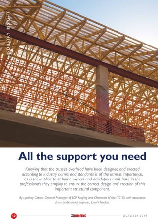
Knowing that the trusses overhead have been designed and erected
according to industry norms and standards is of the utmost importance,
as is the implicit trust home owners and developers must have in the
professionals they employ to ensure the correct design and erection of this
important structural component.
By Lyndsay Cotton, General Manager of LCP Roofing and Chairman of the ITC-SA with assistance
from professional engineer, Errol Hobden.
october 201412
2. T
he word ‘truss’ comes from the very old French word
‘trousse,’ which meant ‘an arrangement or group
of objects bound together.’ From an engineering
perspective, a truss is a rationally designed framework of
structural compression and tension members, arranged in
a series of triangles in order to span large distances, and to
support the dead and live loads to which it will be exposed
during its lifetime.
The truss rests on a wall plate, which is a horizontal load-
bearing member (the support) of an engineer-approved
dimension, of a material fit for the design purpose, and which
must be able to transmit the design loads to the supporting
structure. This wall plate can, for example, be of structural
timber or steel.
The connection of the truss and wall plate is thus engineered by
nature, and it is this connection that is often overlooked by the
designer and erector. The roof truss designer is to
ensure that all structural loads are catered for in the
design of the roof trusses. This will ensure that
dimensionally correct members are used to
accommodate for all the forces that could be applied
to the roof structure of the building, transferring into
the supporting structure below. The incorrect design
of the roof trusses and their connection to the
supporting structure could cause excessive deflections
at the heel supports of the trusses, which could result in wall
cracks and the potential failure of the structure.
Take a masonry wall support in a standard residential application
where the wall is designed to support vertical loads imposed
on it by the roof structure: The wall is designed as a compression
member able to resist vertical loading, but in most cases will
not be able to resist excessive horizontal movement or forces.
The wall designer needs to ensure that the wall is capable of
resisting the horizontal loads imposed on it by the roof
structure.
Support Types and
Support Reactions
When considering supports and reactions, the following
graphic explains best the three typical constraints and forces
experienced in a structure, namely ‘roller’ supports, ‘pinned’
supports and ‘fixed’ supports.
Roller
The connection point on the bar cannot move downward.
Constraints
Pin
The joint cannot move in vertical and horizontal directions.
Fixed Support
The support prevents translation in vertical and horizontal
directions and also rotation.
(to support large corner overhangs)
Industryinsight
octOber 2014 13
3. Trusses are mostly designed with one pinned support and at
least one roller support. From a design calculation point of
view, the roller support will allow the truss to move
horizontally; therefore the truss design needs to ensure that
the truss is stiff enough so that the horizontal movement is
kept to a minimum or within acceptable design standards.
When a truss is designed with one support pinned and the
other support as a roller support, the design calculations will
show that there are no horizontal reactions.
All structural members deflect under load and the horizontal
deflection in a roof structure is an important facet to be
considered in the design of the support structure. SANS
10160-1:2010 recommends that the horizontal deflection in a
wall or column be no more than storey height of the element
divided by 250. For example, a typical residential supporting
wall of say 2 800mm high should not deflect horizontally by
more than 11mm.
When designing roof trusses and especially scissor trusses,
quite often the horizontal deflection will exceed 11mm. Should
this deflection exceed 11mm and be no more than 25mm, a
sliding shoe must be installed on at least one support in order
to allow the truss to deflect without imposing excessive
horizontal loads onto the supporting structure.
There will be instances where the truss designer will be
required to pin the truss at both supports. This should only be
allowed with the approval and consent of the design engineer.
By pinning both supports, the roof truss is then dependent on
the supporting structure, as well as the connection of the truss
to the support structure for its strength. The truss is no longer
a single structural member that is capable of supporting its load
on its own, but is now dependent on the supporting structure
to help it carry the load. The supporting structure must thus
be able to withstand all the forces, as well as the horizontal
forces imposed on it by the roof structure. The structural
engineer responsible for the design of the support structure
needs to be contacted to find out if he has accommodated for
the loads and horizontal loads that the roof will be imposing on
the support structure. The truss engineer and the engineer
responsible for the support structure need to liaise on the
design of the cleat required to anchor the roof trusses to the
support structure.
In some cases the trusses may be required to resist axial loads.
These axial loads could be due to wind or seismic loads and in
some cases they could be due to other structural components
in the structure needing help from the roof trusses to resist,
for example, excessive buckling loads. In these cases it is
imperative that the connection of the roof truss to the
structure be adequate to transfer the loads from the one
structural component to the other.
It is important to note that wire ties or strapping cannot be
considered to adequately transfer horizontal loads into the
support structure. Wire ties or strapping are designed to
resist upward forces generally created by wind.
Support over Openings
Vertical support is equally critical, and whilst this is not within
the ambit of the truss designer’s responsibility, it is the duty of
care of the truss designer to notify the engineer of unusually
large loads imposed on a supporting structure by the roof
trusses. (One of the least understood construction details on
a building site is that of the support of roof structures over
double garage openings.)
Pinned
Support
Roller
Support
Horizontal
Deflection
H - Overall height of
building
Hx - Horizontal
displacement for
storey height
u - Overall horizontal
displacement
ux - Horizontal
displacement over
storey height
Industryinsight
october 201414
4.
5. Industryinsight
According to SANS 10400-K:2011 the lintel depth over a
double garage opening should be no less than 765mm or 9
courses of 85mm deep each, and should be of a grouted cavity
construction, the cavity filled with 25MPa concrete.
Pre-stressed concrete lintels must comply with SANS 1504
and the bearing width (each side of the opening) must be no
less than 350mm. In other words, the pre-stressed lintels over
a typical 4 800mm double garage opening are not to be less
than 5 500mm long and are to be supported for at least 7 days
after completion. Furthermore, it would be wise to introduce
a camber of span/500, which, rounded off, equates to 10mm.
This is easily accomplished by installing the lintels and building
up the ends with brickwork to weigh them down. The lintel is
then jacked up centre by 10mm and the brickwork completed.
There must be a minimum of 2 x Y12 primary reinforcing bars
at the base of the lintel and 1 x Y12 secondary reinforcement
at the top of the lintel. Brick force centres should not be less
than 200mm. The use of 5.6mm hard-drawn wire introduced
in lieu of brick force over all openings will be the preferred
method employed by all professional builders. The brickwork
must also be completed in one shift.
A correctly constructed lintel will adequately support the roof
structure and be able to resist both vertical and horizontal
forces.
For more information please do
not hesitate to contact the
writer for clarification and
expert advice:
(c) 082 564 2730 | 0861 LCPROOF
(e) lyndsay@lcproofing.co.za
(w) www.lcproofing.co.za
Horizontal
Deflection
Horizontal
Deflection
Pinned
Support
Pinned
Support
Excessive Horizontal forces induced into walls
WC - Pre Camber
WS - Deflection under self weight
WL - Long term deflection under permanent or semi-permanent loads
– – - Horizontal line
october 201416