SlideShare uma empresa Scribd logo
1 de 48
Baixar para ler offline
Leonardo Rueda
EML 4535C
CAD/CAM Project Part I
I. Project Goals:
The primary goal for this project was to model and assemble the parts needed to make a snip.
Each part of the assembly was modeled separately and then put together to make the final product.
This project’s goal is to make us more familiar with the program NX by learning how to create
individual parts and also how to put them all together. This software allows us to create 3D
representations of objects with much ease and this is very helpful if one wants to create anything
they want.
II. Description:
Snips which are also known as shears is a type of plier that is mainly used to cut sheet metals
and other tough webs. Snips are divided into two main categories which are compound action snips
and tinner’s snips. These two serve for the same purpose but the difference between them is that
the compound action snips are used for slightly tougher objects than the tinner’s snips. The tinner
snips are one of the most popular, they resemble common scissors, and are defined by their long
handles and short blades. Compound action snips are known as aviation snips because they were
developed to cut aluminum in the construction of aircrafts. Our model seems to be the compound
action type and below is a picture of a real compound action type and our created model along
with the comparison of the individual parts.
III. Cad Part:
Handle:
Sketch # 1:
• Sketch was done on the XY plane
• Dimensions and constraints were made and labeled
• Holes sizes are important for future parts
• Once Sketch was made and with the proper dimensions, the figure was extruded
• The figure was extruded 5/16”
• Region Boundary Curve was used on the extrude
• A second Sketch was made on top of the first one
• Dimensions were added
• The next step was to extrude the new shape made
• It was extruded to 1.5 inches
• After this Edge blend was used to blend the two shapes together
• The next step was to use mirror feature
• In this feature both the extrude and Edge Blend parts were selected and mirror to the XY
plane
• The next step was to extrude again. This time the shape being extruded was the little
triangle on the top left part using region boundary curve
• After it was extruded, it was subtracted from the shape
• The next step was to edge blend again. This time the edge blend was applied to the sides
of the shape
• Mirror feature was used again to apply the same process on the other side
• The next step was to use the shell feature
• A thickness of 0.08 was used
• At last, a third edge blend was used for the top and bottom side of the figure
Grip Y
The sketch from the handle part was reused to make the grip.
At this point the shell feature from the previous part was taken out.
At this point a first extrude was made.
A sketch was made on top of the figure already made.
The new sketch was then extruded.
At this point several edge blends were made and implemented to the figure.
After the edge blends, the chamfer feature was implemented.
At this point a second edge blend was used.
After the second edge blend, the subtract feature was used to take out part of the figure as
you can see on the above picture.
The next step was to use the instance geometry feature.
After the instance geometry feature, the unite feature was used to combine the top and
bottom shapes.
At this point, a datum plane was created.
The datum plane was created to then make a sketch on the plane which one can see on the
picture above.
The newly made sketch was then extruded as illustrated on the picture above.
The next step was to use the offset surface feature.
The next step was to create a final sketch on the side of the figure as one can see on
the picture above.
The new sketch was then extruded.
Finally, the pattern feature was used to create the indentations that can be
seen on the above picture.
Blade:
The first thing that was done was to make a new sketch on the x-y plane.
After the sketch was made, the figure was extruded with the following dimensions that can
be seen on the figure above. Only the biggest solid body was extruded on this step.
On this step, the bigger circle was also extruded.
The next step was to create a Datum Plane on the side of the figure.
At this point, a second sketch was made on top on the datum plane created on the previous
step.
The newly made sketch was then extruded as shown on the figure above.
The next step was to edge blend the new shape on the highlighted areas seen on the figure
above.
After the edge blend was done, the draft feature was used on the highlighted area above.
The next step was to make the sketch of the actual blade. This sketch was made on top of
the solid body as shown above.
The next step was to apply more edge blends on the highlighted parts shown above.
The next step was to create several datum planes as illustrated on the figure above.
After the datum planes were finished, the next step was to create a sketch for each datum
plane created. One can see each of the sketched on the figure above.
After the sketches were made, each of the sketches were swept using the same direction as
illustrated on the figure above.
After the swept was completed, the unite feature was used to unite the base of the blade
with the top of the blade to make it possible to use edge blend on the next step.
This was the last step, which was to use a final edge blend on the edge between the base of
the blade and the top of the blade to make it smoother surface. This edge blend was possible by
the unite feature implemented on the previous step.
Grip R
This second grip was made almost the same way as the first one. The first thing that was
done was to reuse the handle. After the handle was pulled up, the shell feature was taken out and
this can be seen on the figure below. Also the third lower circle was erased from the figure.
A second sketch was made was can be seen on the figure above. New measurements
were taken.
After the second sketch was made, it was extruded as portrayed on the figure above.
After the figure was extruded, the nest step was to use edge blend on some of the
edges to make the surface smoother as seen on the two figures above.
At this point another sketch was made at the bottom of the figure which was then extruded
and subtracted from the main figure to create a hole that you can see on the figure above. At this
point some edge blends were also made to smooth the edges.
At this point, the handle was subtracted from the grip and mirrored as portrayed on the
figure above.
At this point, another sketch was made on the top of the figure and then it was extruded
and cut from the figure as illustrated on the figure above.
At this point, the grip was done, but an extra step was made which was to cut a pattern
indentations as illustrated on the figure above.
Assembly
The first thing that was done was to obviously open NX and choose the assembly feature
in order to put everything together. The first figure that was imported into the assembly was the
blade ad can be seen on the figure above.
The next step was to add the handle plus the Y grip already combined together as one
figure. This was done by a feature from assembly that allows to choose two figure at the same time
and combine them before uploading it to the assembly file. We called this a sub assembly.
The next step was the same as the previous step but this time it was the handle and the R
grip together as can be seen on the figure above. At this point, all of the individual pieces were
added into the assembly file and now it was just a matter of adding constraints to the figures to
properly attach them to one another.
The figure above shows the final assembly completed and it also shows all of the constrains
that were implemented on the part navigator located on the left side of the figure. These constraints
included fix, concentric, center, fit and touch constraints.
The figure above illustrates the drafting feature.
IV. Summary:
In conclusion, the goal of this project was to learn the NX program by making a snip. NX
provided more than what was necessary to complete this project. The NX program provides us
with an easy tool to come up with designs. It serves us as a drawing board to any potential
design. Our created model turned out to be very close to the actual object which means, that it
was a success in both making the object and learning the program.
V. CAD/CAM PROJECT Part II
Finite Element Analysis:
.
The first thing that was done was to import the previous model that was created in part I
and start an advanced simulations in order to have an idealized part.
The next step that was done was to promote the model in order to split it into four different
parts.
The next step that was taken was to find the midpoint of both handles as illustrated on the
figure above.
At this point, the split body feature was used on both handles. At this point we switched to
FEM 3.
The next step was to use the merge feature as illustrated on the figure above.
The next step taken was to do a 2D mesh on both handles as illustrated on the figure above.
The 2D mesh feature was used and each handle was done individually with a 0.05 element size.
The same exact process was repeated but this time it was implemented on the lower part of
both blades. The same 0.05 element size was used for these two parts. The right figure illustrates
the 2D mesh on both the blades and handles.
The next step was to use the copy and reflect feature on only the handles as illustrated
above.
At this point, he handles are done and moved on onto the blades. A 3D tetrahedral Mesh
was created for both blades individually with a 0.1 element size for both blades.
The next step was to create some element nodes at the tips of the blades and connect them
with one another.
After creating the element nodes, thickness was added to both handles and the 2D thin
blades. The thickness added to the handles was that of 0.08 and the thickness for the 2D thin blades
was 0.26.
The next step was to create nodes illustrated as red on the figure above on both handles.
The nodes were right at the center of each hole.
The next step was to use the 1d Connection tools in order to create the spider web looking
things illustrated on the figure above.
At this point, there are two nodes on each of the six circles. A C-Bush was created as
illustrated on the figure above in order to connect the nodes together in a straight line.
At this point, the same process is repeated on the top circles of the handles.
The same process was done on the holes of the blade as illustrated on the figure above. The
next step was to create a bushing on it, although it cannot be seen on the figure. After this step was
done, we switch from FEM to SIM.
The next step is to create regions for gluing. In order to do this, the edge to surface feature
was used for both sides of the handles as illustrated on the figure above.
The next step was to make a fix constraint at the midpoint of the nylon bar as illustrated in
the figure above.
The next step was to make two user defined constraints on each handle in order to prevent
rotation and these constraints are labeled blue on the figure above.
The next step was to create two 10 pound load forces at the end of the midpoint of both
handles at opposite directions. These forces are labeled red on the figure above.
The next step was to a group for output that included all the bushing plus the nylon bar.
The next step was to solve it and the figure above shows the results.
At this point, I entered my name into nx.
The next step was to change the coordinate system to CSYS and also we changed the nodes
to the CSYS system.
At this point we ran the results again as illustrated on the figure above.
The next step was to go to the sim and click the assembly snip PRT in order to get to the
idealized part illustrated by the picture above.
The next step was to use the split body tool at the highlighted part illustrated on the figure
above.
The next step was to selection a bean section of the surface in the direction of the orange
arrow illustrated on the figure above. After this, evaluate section properties was opened in order
to get the information for the hand calculations.
The figure above shows the data needed for the hand calculations.
The figure above shows the pressure values at the top using the identify feature. These
values can be used to compare with the hand calculations in order to obtain percent error.
The figure above shows the pressure results at the bottom.
VI. Hand Calculations:
% taking in consideration figure AA the vertical dimentions from
% NX measuremen tool are
d1 = 3.8399;
d2 = 1.8606;
d3 = 1.0455;
d4 = 6.6315;
Bx = -10*(d4/d3)
N = -Bx*(d2/d1)
Dx = N-Bx
Cx = Bx+10
% to calculate the stress utilizing the I provided by
%the information on Identity results.
L = 3.7033;
M = 10*cos(9.5361)*L;
yt = 0.24;
yc = 0.312077;
I = 0.002797;
% The results for Stress in Tention are given by
F1 = -(M*yt)/I
% The result for Stress
F2 = -(M*yc)/I
Bx =
-63.4290
N =
30.7341
Dx =
94.1631
Cx =
-53.4290
F1 =
3.1580e+03
F2 =
4.1064e+03
>>
VII. Conclusion
In conclusion, by the use of the NX program, the results achieved through NX were
close to the actual ones of the real object. Also the simulation that run through NX gave
the same results that were calculated by the hand calculations. The making of this project
tough us a lot from the NX program. Since the beginning of the project were it taught us
the basics of the program like making simple sketches all the way up to the end of the
project were one was able to run simulations, create meshes, and problem solving
techniques that were encountered along the way. The true goal of this project was to
essentially learn the NX software by the use of many of its different features that were
implemented throughout the whole project, and the goal was achieved.
VIII. References:
• "Snips." Wikipedia. Wikimedia Foundation, 11 Feb. 2015. Web. 16 Mar. 2015.
• Lab 1 Video
https://www.youtube.com/watch?v=ZbhBIBclVmM
• Lab 2 video
https://www.youtube.com/watch?v=6bLA3y_EJJM
• Lab 3 Video
https://www.youtube.com/watch?v=EfLvrVfNuig
• Lab 4 video
https://www.youtube.com/watch?v=K8T-UC8lWgI
• Lab 5 video
https://www.youtube.com/watch?v=xZ5hs6Pyzqo
• Lab 6 video
https://www.youtube.com/watch?v=7jzpImoQlmk

Mais conteúdo relacionado

Mais procurados

Computer Aided Design and Modeling Final Report
Computer Aided Design and Modeling Final ReportComputer Aided Design and Modeling Final Report
Computer Aided Design and Modeling Final ReportRichard Horta
 
Lesson loft
Lesson loftLesson loft
Lesson loftMr_Burns
 
Lesson revolve
Lesson revolveLesson revolve
Lesson revolveMr_Burns
 
Isometric projection.pdf
Isometric projection.pdfIsometric projection.pdf
Isometric projection.pdfssuser9831e9
 
Pictorial projection
Pictorial projectionPictorial projection
Pictorial projectionmusadoto
 
Silhouettes and Outlines
Silhouettes and OutlinesSilhouettes and Outlines
Silhouettes and Outlinesrascalfats
 
2.1.a isometric obliquepictorials
2.1.a  isometric obliquepictorials2.1.a  isometric obliquepictorials
2.1.a isometric obliquepictorialsjoeyrsl
 
Automated Laser Reflection Report
Automated Laser Reflection ReportAutomated Laser Reflection Report
Automated Laser Reflection ReportNan Li
 
Mechanical Drafting. Sectional Orthography
Mechanical Drafting. Sectional OrthographyMechanical Drafting. Sectional Orthography
Mechanical Drafting. Sectional OrthographyGaurav Mistry
 

Mais procurados (19)

Computer Aided Design and Modeling Final Report
Computer Aided Design and Modeling Final ReportComputer Aided Design and Modeling Final Report
Computer Aided Design and Modeling Final Report
 
Lesson loft
Lesson loftLesson loft
Lesson loft
 
Lesson revolve
Lesson revolveLesson revolve
Lesson revolve
 
sectional views
sectional viewssectional views
sectional views
 
Isometric projection.pdf
Isometric projection.pdfIsometric projection.pdf
Isometric projection.pdf
 
Sectional View
Sectional ViewSectional View
Sectional View
 
Pictorial projection
Pictorial projectionPictorial projection
Pictorial projection
 
Silhouettes and Outlines
Silhouettes and OutlinesSilhouettes and Outlines
Silhouettes and Outlines
 
Pictorial Drawings
Pictorial DrawingsPictorial Drawings
Pictorial Drawings
 
Lesson6
Lesson6Lesson6
Lesson6
 
2.1.a isometric obliquepictorials
2.1.a  isometric obliquepictorials2.1.a  isometric obliquepictorials
2.1.a isometric obliquepictorials
 
Automated Laser Reflection Report
Automated Laser Reflection ReportAutomated Laser Reflection Report
Automated Laser Reflection Report
 
Final portfolio
Final portfolioFinal portfolio
Final portfolio
 
Mechanical Drafting. Sectional Orthography
Mechanical Drafting. Sectional OrthographyMechanical Drafting. Sectional Orthography
Mechanical Drafting. Sectional Orthography
 
Section views
Section viewsSection views
Section views
 
Max2015 ch02
Max2015 ch02Max2015 ch02
Max2015 ch02
 
Max2015 ch03
Max2015 ch03Max2015 ch03
Max2015 ch03
 
Perspective Drawing
Perspective DrawingPerspective Drawing
Perspective Drawing
 
978 1-58503-754-4-1 (1)
978 1-58503-754-4-1 (1)978 1-58503-754-4-1 (1)
978 1-58503-754-4-1 (1)
 

Destaque

Modelo osi
Modelo osiModelo osi
Modelo osistingjo
 
Desarrollo mis competencias 2
Desarrollo mis competencias 2Desarrollo mis competencias 2
Desarrollo mis competencias 2Roger Martinez
 
КАТАЛОГ УСЛУГ МЕЖРЕГИОНАЛЬНОЙ ОБЩЕСТВЕННОЙ ОРГАНИЗАЦИИ «АУДИТОРЫ КОРПОРАТИВНО...
КАТАЛОГ УСЛУГ МЕЖРЕГИОНАЛЬНОЙ ОБЩЕСТВЕННОЙ ОРГАНИЗАЦИИ «АУДИТОРЫ КОРПОРАТИВНО...КАТАЛОГ УСЛУГ МЕЖРЕГИОНАЛЬНОЙ ОБЩЕСТВЕННОЙ ОРГАНИЗАЦИИ «АУДИТОРЫ КОРПОРАТИВНО...
КАТАЛОГ УСЛУГ МЕЖРЕГИОНАЛЬНОЙ ОБЩЕСТВЕННОЙ ОРГАНИЗАЦИИ «АУДИТОРЫ КОРПОРАТИВНО...MOO АКБ
 
2557 project
2557 project 2557 project
2557 project jjrrwnd
 
Proyecto de informatica
Proyecto de informaticaProyecto de informatica
Proyecto de informaticaMariana Canto
 
De noodzakelijke basisvoorzieningen voor beter digitaal leren: Casus CVO-AV -...
De noodzakelijke basisvoorzieningen voor beter digitaal leren: Casus CVO-AV -...De noodzakelijke basisvoorzieningen voor beter digitaal leren: Casus CVO-AV -...
De noodzakelijke basisvoorzieningen voor beter digitaal leren: Casus CVO-AV -...SURF Events
 
Erwan Le Roux et Cardinal Edifice vainqueurs de la Route du Rhum en classe M...
Erwan Le Roux  et Cardinal Edifice vainqueurs de la Route du Rhum en classe M...Erwan Le Roux  et Cardinal Edifice vainqueurs de la Route du Rhum en classe M...
Erwan Le Roux et Cardinal Edifice vainqueurs de la Route du Rhum en classe M...Esperluette & Associés
 
Top 10 social media tips
Top 10 social media tipsTop 10 social media tips
Top 10 social media tipsCliff Ashcroft
 
Horario de clases
Horario  de  clasesHorario  de  clases
Horario de clasesdagmarl
 
College Planning Certificate
College Planning CertificateCollege Planning Certificate
College Planning CertificateLandon Ford
 
The role of informal sector in alleviating youth unemployment
The role of informal sector in alleviating youth unemploymentThe role of informal sector in alleviating youth unemployment
The role of informal sector in alleviating youth unemploymentDr Lendy Spires
 
Tabungan pendidikan sejahtera revisi
Tabungan pendidikan sejahtera   revisiTabungan pendidikan sejahtera   revisi
Tabungan pendidikan sejahtera revisipakdewahyudi
 
Guerra federal
Guerra federalGuerra federal
Guerra federallorelolli
 

Destaque (17)

VENGATESAN - Resume
VENGATESAN -  ResumeVENGATESAN -  Resume
VENGATESAN - Resume
 
Modelo osi
Modelo osiModelo osi
Modelo osi
 
Desarrollo mis competencias 2
Desarrollo mis competencias 2Desarrollo mis competencias 2
Desarrollo mis competencias 2
 
КАТАЛОГ УСЛУГ МЕЖРЕГИОНАЛЬНОЙ ОБЩЕСТВЕННОЙ ОРГАНИЗАЦИИ «АУДИТОРЫ КОРПОРАТИВНО...
КАТАЛОГ УСЛУГ МЕЖРЕГИОНАЛЬНОЙ ОБЩЕСТВЕННОЙ ОРГАНИЗАЦИИ «АУДИТОРЫ КОРПОРАТИВНО...КАТАЛОГ УСЛУГ МЕЖРЕГИОНАЛЬНОЙ ОБЩЕСТВЕННОЙ ОРГАНИЗАЦИИ «АУДИТОРЫ КОРПОРАТИВНО...
КАТАЛОГ УСЛУГ МЕЖРЕГИОНАЛЬНОЙ ОБЩЕСТВЕННОЙ ОРГАНИЗАЦИИ «АУДИТОРЫ КОРПОРАТИВНО...
 
2557 project
2557 project 2557 project
2557 project
 
Proyecto de informatica
Proyecto de informaticaProyecto de informatica
Proyecto de informatica
 
De noodzakelijke basisvoorzieningen voor beter digitaal leren: Casus CVO-AV -...
De noodzakelijke basisvoorzieningen voor beter digitaal leren: Casus CVO-AV -...De noodzakelijke basisvoorzieningen voor beter digitaal leren: Casus CVO-AV -...
De noodzakelijke basisvoorzieningen voor beter digitaal leren: Casus CVO-AV -...
 
Erwan Le Roux et Cardinal Edifice vainqueurs de la Route du Rhum en classe M...
Erwan Le Roux  et Cardinal Edifice vainqueurs de la Route du Rhum en classe M...Erwan Le Roux  et Cardinal Edifice vainqueurs de la Route du Rhum en classe M...
Erwan Le Roux et Cardinal Edifice vainqueurs de la Route du Rhum en classe M...
 
Top 10 social media tips
Top 10 social media tipsTop 10 social media tips
Top 10 social media tips
 
CTE Graduation Guide - CFBISD
CTE Graduation Guide - CFBISDCTE Graduation Guide - CFBISD
CTE Graduation Guide - CFBISD
 
Horario de clases
Horario  de  clasesHorario  de  clases
Horario de clases
 
College Planning Certificate
College Planning CertificateCollege Planning Certificate
College Planning Certificate
 
Sida 1
Sida 1Sida 1
Sida 1
 
The role of informal sector in alleviating youth unemployment
The role of informal sector in alleviating youth unemploymentThe role of informal sector in alleviating youth unemployment
The role of informal sector in alleviating youth unemployment
 
Task 2
Task 2Task 2
Task 2
 
Tabungan pendidikan sejahtera revisi
Tabungan pendidikan sejahtera   revisiTabungan pendidikan sejahtera   revisi
Tabungan pendidikan sejahtera revisi
 
Guerra federal
Guerra federalGuerra federal
Guerra federal
 

Semelhante a Final report

Solid_Modeling_Project_Reverse engineering of a computer mouse and documentat...
Solid_Modeling_Project_Reverse engineering of a computer mouse and documentat...Solid_Modeling_Project_Reverse engineering of a computer mouse and documentat...
Solid_Modeling_Project_Reverse engineering of a computer mouse and documentat...Mehmet Bariskan
 
Cadcam mid term report
Cadcam mid term reportCadcam mid term report
Cadcam mid term reportJose Olvera
 
A graphic library and an application for simple curve manipolation
A graphic library and an application for simple curve manipolationA graphic library and an application for simple curve manipolation
A graphic library and an application for simple curve manipolationgraphitech
 
An%20Intermediate%20Google%20SketchUp%20Tutorial%20-%20Part%203
An%20Intermediate%20Google%20SketchUp%20Tutorial%20-%20Part%203An%20Intermediate%20Google%20SketchUp%20Tutorial%20-%20Part%203
An%20Intermediate%20Google%20SketchUp%20Tutorial%20-%20Part%203tutorialsruby
 
An%20Intermediate%20Google%20SketchUp%20Tutorial%20-%20Part%203
An%20Intermediate%20Google%20SketchUp%20Tutorial%20-%20Part%203An%20Intermediate%20Google%20SketchUp%20Tutorial%20-%20Part%203
An%20Intermediate%20Google%20SketchUp%20Tutorial%20-%20Part%203tutorialsruby
 
Porfolio Power Point
Porfolio Power PointPorfolio Power Point
Porfolio Power Pointjholtsclaw6
 
ME430FinalReport (1)
ME430FinalReport (1)ME430FinalReport (1)
ME430FinalReport (1)Ivan Romano
 
Computer Aided Solid Modelling
Computer Aided Solid ModellingComputer Aided Solid Modelling
Computer Aided Solid ModellingDibyajyoti Laha
 
Model and texture a photorealistic usb cable with maya and mental ray
Model and texture a photorealistic usb cable with maya and mental rayModel and texture a photorealistic usb cable with maya and mental ray
Model and texture a photorealistic usb cable with maya and mental raySandra Montoya
 
Study on pattern making of a given T-shirt using CAD.
Study on pattern making of a given T-shirt using CAD.Study on pattern making of a given T-shirt using CAD.
Study on pattern making of a given T-shirt using CAD.NazmulHasanAnan
 
Google sketchup8
Google sketchup8Google sketchup8
Google sketchup8Trianz King
 
Google sketchup8
Google sketchup8Google sketchup8
Google sketchup8Trianz King
 
Assembly & mates
Assembly & matesAssembly & mates
Assembly & matesMr_Burns
 
Catia v5 workbook
Catia v5 workbookCatia v5 workbook
Catia v5 workbookZAKI ANWER
 
AutoCAD Lab Manual
AutoCAD Lab ManualAutoCAD Lab Manual
AutoCAD Lab ManualCynthia King
 

Semelhante a Final report (20)

FEM Paper
FEM PaperFEM Paper
FEM Paper
 
Solid_Modeling_Project_Reverse engineering of a computer mouse and documentat...
Solid_Modeling_Project_Reverse engineering of a computer mouse and documentat...Solid_Modeling_Project_Reverse engineering of a computer mouse and documentat...
Solid_Modeling_Project_Reverse engineering of a computer mouse and documentat...
 
Cadcam mid term report
Cadcam mid term reportCadcam mid term report
Cadcam mid term report
 
A graphic library and an application for simple curve manipolation
A graphic library and an application for simple curve manipolationA graphic library and an application for simple curve manipolation
A graphic library and an application for simple curve manipolation
 
An%20Intermediate%20Google%20SketchUp%20Tutorial%20-%20Part%203
An%20Intermediate%20Google%20SketchUp%20Tutorial%20-%20Part%203An%20Intermediate%20Google%20SketchUp%20Tutorial%20-%20Part%203
An%20Intermediate%20Google%20SketchUp%20Tutorial%20-%20Part%203
 
An%20Intermediate%20Google%20SketchUp%20Tutorial%20-%20Part%203
An%20Intermediate%20Google%20SketchUp%20Tutorial%20-%20Part%203An%20Intermediate%20Google%20SketchUp%20Tutorial%20-%20Part%203
An%20Intermediate%20Google%20SketchUp%20Tutorial%20-%20Part%203
 
Porfolio Power Point
Porfolio Power PointPorfolio Power Point
Porfolio Power Point
 
FEA Final Project
FEA Final ProjectFEA Final Project
FEA Final Project
 
ME430FinalReport (1)
ME430FinalReport (1)ME430FinalReport (1)
ME430FinalReport (1)
 
Computer Aided Solid Modelling
Computer Aided Solid ModellingComputer Aided Solid Modelling
Computer Aided Solid Modelling
 
Model and texture a photorealistic usb cable with maya and mental ray
Model and texture a photorealistic usb cable with maya and mental rayModel and texture a photorealistic usb cable with maya and mental ray
Model and texture a photorealistic usb cable with maya and mental ray
 
Production log
Production logProduction log
Production log
 
Icem102
Icem102Icem102
Icem102
 
Unit Work Planes
Unit Work PlanesUnit Work Planes
Unit Work Planes
 
Study on pattern making of a given T-shirt using CAD.
Study on pattern making of a given T-shirt using CAD.Study on pattern making of a given T-shirt using CAD.
Study on pattern making of a given T-shirt using CAD.
 
Google sketchup8
Google sketchup8Google sketchup8
Google sketchup8
 
Google sketchup8
Google sketchup8Google sketchup8
Google sketchup8
 
Assembly & mates
Assembly & matesAssembly & mates
Assembly & mates
 
Catia v5 workbook
Catia v5 workbookCatia v5 workbook
Catia v5 workbook
 
AutoCAD Lab Manual
AutoCAD Lab ManualAutoCAD Lab Manual
AutoCAD Lab Manual
 

Final report

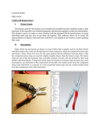
  • 1. Leonardo Rueda EML 4535C CAD/CAM Project Part I I. Project Goals: The primary goal for this project was to model and assemble the parts needed to make a snip. Each part of the assembly was modeled separately and then put together to make the final product. This project’s goal is to make us more familiar with the program NX by learning how to create individual parts and also how to put them all together. This software allows us to create 3D representations of objects with much ease and this is very helpful if one wants to create anything they want. II. Description: Snips which are also known as shears is a type of plier that is mainly used to cut sheet metals and other tough webs. Snips are divided into two main categories which are compound action snips and tinner’s snips. These two serve for the same purpose but the difference between them is that the compound action snips are used for slightly tougher objects than the tinner’s snips. The tinner snips are one of the most popular, they resemble common scissors, and are defined by their long handles and short blades. Compound action snips are known as aviation snips because they were developed to cut aluminum in the construction of aircrafts. Our model seems to be the compound action type and below is a picture of a real compound action type and our created model along with the comparison of the individual parts.
  • 2.
  • 4. • Sketch was done on the XY plane • Dimensions and constraints were made and labeled • Holes sizes are important for future parts • Once Sketch was made and with the proper dimensions, the figure was extruded • The figure was extruded 5/16” • Region Boundary Curve was used on the extrude • A second Sketch was made on top of the first one
  • 5. • Dimensions were added • The next step was to extrude the new shape made • It was extruded to 1.5 inches • After this Edge blend was used to blend the two shapes together
  • 6. • The next step was to use mirror feature • In this feature both the extrude and Edge Blend parts were selected and mirror to the XY plane • The next step was to extrude again. This time the shape being extruded was the little triangle on the top left part using region boundary curve • After it was extruded, it was subtracted from the shape
  • 7. • The next step was to edge blend again. This time the edge blend was applied to the sides of the shape
  • 8. • Mirror feature was used again to apply the same process on the other side • The next step was to use the shell feature • A thickness of 0.08 was used
  • 9. • At last, a third edge blend was used for the top and bottom side of the figure Grip Y The sketch from the handle part was reused to make the grip. At this point the shell feature from the previous part was taken out.
  • 10. At this point a first extrude was made. A sketch was made on top of the figure already made.
  • 11. The new sketch was then extruded.
  • 12. At this point several edge blends were made and implemented to the figure. After the edge blends, the chamfer feature was implemented.
  • 13. At this point a second edge blend was used. After the second edge blend, the subtract feature was used to take out part of the figure as you can see on the above picture.
  • 14. The next step was to use the instance geometry feature. After the instance geometry feature, the unite feature was used to combine the top and bottom shapes.
  • 15. At this point, a datum plane was created. The datum plane was created to then make a sketch on the plane which one can see on the picture above.
  • 16. The newly made sketch was then extruded as illustrated on the picture above. The next step was to use the offset surface feature.
  • 17. The next step was to create a final sketch on the side of the figure as one can see on the picture above. The new sketch was then extruded.
  • 18. Finally, the pattern feature was used to create the indentations that can be seen on the above picture.
  • 19. Blade: The first thing that was done was to make a new sketch on the x-y plane. After the sketch was made, the figure was extruded with the following dimensions that can be seen on the figure above. Only the biggest solid body was extruded on this step.
  • 20. On this step, the bigger circle was also extruded. The next step was to create a Datum Plane on the side of the figure.
  • 21. At this point, a second sketch was made on top on the datum plane created on the previous step. The newly made sketch was then extruded as shown on the figure above.
  • 22. The next step was to edge blend the new shape on the highlighted areas seen on the figure above. After the edge blend was done, the draft feature was used on the highlighted area above.
  • 23. The next step was to make the sketch of the actual blade. This sketch was made on top of the solid body as shown above. The next step was to apply more edge blends on the highlighted parts shown above.
  • 24. The next step was to create several datum planes as illustrated on the figure above. After the datum planes were finished, the next step was to create a sketch for each datum plane created. One can see each of the sketched on the figure above.
  • 25. After the sketches were made, each of the sketches were swept using the same direction as illustrated on the figure above. After the swept was completed, the unite feature was used to unite the base of the blade with the top of the blade to make it possible to use edge blend on the next step.
  • 26. This was the last step, which was to use a final edge blend on the edge between the base of the blade and the top of the blade to make it smoother surface. This edge blend was possible by the unite feature implemented on the previous step. Grip R This second grip was made almost the same way as the first one. The first thing that was done was to reuse the handle. After the handle was pulled up, the shell feature was taken out and this can be seen on the figure below. Also the third lower circle was erased from the figure.
  • 27. A second sketch was made was can be seen on the figure above. New measurements were taken. After the second sketch was made, it was extruded as portrayed on the figure above.
  • 28. After the figure was extruded, the nest step was to use edge blend on some of the edges to make the surface smoother as seen on the two figures above. At this point another sketch was made at the bottom of the figure which was then extruded and subtracted from the main figure to create a hole that you can see on the figure above. At this point some edge blends were also made to smooth the edges.
  • 29. At this point, the handle was subtracted from the grip and mirrored as portrayed on the figure above. At this point, another sketch was made on the top of the figure and then it was extruded and cut from the figure as illustrated on the figure above.
  • 30. At this point, the grip was done, but an extra step was made which was to cut a pattern indentations as illustrated on the figure above. Assembly The first thing that was done was to obviously open NX and choose the assembly feature in order to put everything together. The first figure that was imported into the assembly was the blade ad can be seen on the figure above.
  • 31. The next step was to add the handle plus the Y grip already combined together as one figure. This was done by a feature from assembly that allows to choose two figure at the same time and combine them before uploading it to the assembly file. We called this a sub assembly. The next step was the same as the previous step but this time it was the handle and the R grip together as can be seen on the figure above. At this point, all of the individual pieces were added into the assembly file and now it was just a matter of adding constraints to the figures to properly attach them to one another.
  • 32. The figure above shows the final assembly completed and it also shows all of the constrains that were implemented on the part navigator located on the left side of the figure. These constraints included fix, concentric, center, fit and touch constraints. The figure above illustrates the drafting feature.
  • 33. IV. Summary: In conclusion, the goal of this project was to learn the NX program by making a snip. NX provided more than what was necessary to complete this project. The NX program provides us with an easy tool to come up with designs. It serves us as a drawing board to any potential design. Our created model turned out to be very close to the actual object which means, that it was a success in both making the object and learning the program. V. CAD/CAM PROJECT Part II Finite Element Analysis: . The first thing that was done was to import the previous model that was created in part I and start an advanced simulations in order to have an idealized part.
  • 34. The next step that was done was to promote the model in order to split it into four different parts. The next step that was taken was to find the midpoint of both handles as illustrated on the figure above. At this point, the split body feature was used on both handles. At this point we switched to FEM 3.
  • 35. The next step was to use the merge feature as illustrated on the figure above. The next step taken was to do a 2D mesh on both handles as illustrated on the figure above. The 2D mesh feature was used and each handle was done individually with a 0.05 element size. The same exact process was repeated but this time it was implemented on the lower part of both blades. The same 0.05 element size was used for these two parts. The right figure illustrates the 2D mesh on both the blades and handles.
  • 36. The next step was to use the copy and reflect feature on only the handles as illustrated above. At this point, he handles are done and moved on onto the blades. A 3D tetrahedral Mesh was created for both blades individually with a 0.1 element size for both blades. The next step was to create some element nodes at the tips of the blades and connect them with one another.
  • 37. After creating the element nodes, thickness was added to both handles and the 2D thin blades. The thickness added to the handles was that of 0.08 and the thickness for the 2D thin blades was 0.26. The next step was to create nodes illustrated as red on the figure above on both handles. The nodes were right at the center of each hole.
  • 38. The next step was to use the 1d Connection tools in order to create the spider web looking things illustrated on the figure above. At this point, there are two nodes on each of the six circles. A C-Bush was created as illustrated on the figure above in order to connect the nodes together in a straight line. At this point, the same process is repeated on the top circles of the handles.
  • 39. The same process was done on the holes of the blade as illustrated on the figure above. The next step was to create a bushing on it, although it cannot be seen on the figure. After this step was done, we switch from FEM to SIM. The next step is to create regions for gluing. In order to do this, the edge to surface feature was used for both sides of the handles as illustrated on the figure above. The next step was to make a fix constraint at the midpoint of the nylon bar as illustrated in the figure above.
  • 40. The next step was to make two user defined constraints on each handle in order to prevent rotation and these constraints are labeled blue on the figure above. The next step was to create two 10 pound load forces at the end of the midpoint of both handles at opposite directions. These forces are labeled red on the figure above. The next step was to a group for output that included all the bushing plus the nylon bar.
  • 41. The next step was to solve it and the figure above shows the results. At this point, I entered my name into nx.
  • 42. The next step was to change the coordinate system to CSYS and also we changed the nodes to the CSYS system. At this point we ran the results again as illustrated on the figure above.
  • 43. The next step was to go to the sim and click the assembly snip PRT in order to get to the idealized part illustrated by the picture above. The next step was to use the split body tool at the highlighted part illustrated on the figure above.
  • 44. The next step was to selection a bean section of the surface in the direction of the orange arrow illustrated on the figure above. After this, evaluate section properties was opened in order to get the information for the hand calculations. The figure above shows the data needed for the hand calculations.
  • 45. The figure above shows the pressure values at the top using the identify feature. These values can be used to compare with the hand calculations in order to obtain percent error. The figure above shows the pressure results at the bottom.
  • 46. VI. Hand Calculations: % taking in consideration figure AA the vertical dimentions from % NX measuremen tool are d1 = 3.8399; d2 = 1.8606; d3 = 1.0455; d4 = 6.6315; Bx = -10*(d4/d3) N = -Bx*(d2/d1) Dx = N-Bx Cx = Bx+10 % to calculate the stress utilizing the I provided by %the information on Identity results. L = 3.7033; M = 10*cos(9.5361)*L; yt = 0.24; yc = 0.312077; I = 0.002797; % The results for Stress in Tention are given by F1 = -(M*yt)/I % The result for Stress F2 = -(M*yc)/I Bx = -63.4290 N =
  • 47. 30.7341 Dx = 94.1631 Cx = -53.4290 F1 = 3.1580e+03 F2 = 4.1064e+03 >> VII. Conclusion In conclusion, by the use of the NX program, the results achieved through NX were close to the actual ones of the real object. Also the simulation that run through NX gave the same results that were calculated by the hand calculations. The making of this project
  • 48. tough us a lot from the NX program. Since the beginning of the project were it taught us the basics of the program like making simple sketches all the way up to the end of the project were one was able to run simulations, create meshes, and problem solving techniques that were encountered along the way. The true goal of this project was to essentially learn the NX software by the use of many of its different features that were implemented throughout the whole project, and the goal was achieved. VIII. References: • "Snips." Wikipedia. Wikimedia Foundation, 11 Feb. 2015. Web. 16 Mar. 2015. • Lab 1 Video https://www.youtube.com/watch?v=ZbhBIBclVmM • Lab 2 video https://www.youtube.com/watch?v=6bLA3y_EJJM • Lab 3 Video https://www.youtube.com/watch?v=EfLvrVfNuig • Lab 4 video https://www.youtube.com/watch?v=K8T-UC8lWgI • Lab 5 video https://www.youtube.com/watch?v=xZ5hs6Pyzqo • Lab 6 video https://www.youtube.com/watch?v=7jzpImoQlmk