1. 1
CHAPTER-1
CENTRAL TESTING LAB (C.T.L.)
1.1) Introduction
Central Testing Laboratory, Jodhpur Discom, Jodhpur is situated at the New
Power House at Shastri Nagar, Jodhpur. In this lab various power system equipment
are tested for providing better operation of power system like insulator , transformer ,
cables , conductor etc.
1.2) Conductor
A conductor which is an object or type of material that allows the flow of
electrical current in one or more direction.
For example a wire is an electrical conductor that can carry electricity along its
length.
Example- Al, Cu.
1.2.1)Types of Conductor
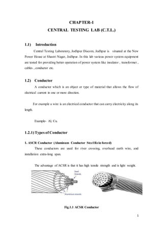
1. ASCR Conductor (Aluminum Conductor Steel Rein forced)
These conductors are used for river crossing, overhead earth wire, and
installation extra-long span.
The advantage of ACSR is that it has high tensile strength and is light weight.
Fig.1.1 ACSR Conductor
2. 2
2. AAC Conductor (All Aluminum Conductor)
AAC Conductor is used mainly in urban areas where the spacing is short and
the supports are closer together.
The advantage of AAC Conductor is that they have a high degree of corrosion
resistance.
Fig 1.2 AAC Conductor
3. AAAC Conductor (All aluminum Alloy Conductor)
AAAC Conductor is used as bare overhead conductor for power transmission
and distribution lines on aerial circuit that require larger mechanical resistance than
AAC.
AAAC cables have lower weight per unit length and slightly lower resistance
per unit length than ACSR.
Types of ACSR Conductor
1. Zebra ACSR Conductor
2. Panther ACSR Conductor
3. Dog ACSR Conductor
4. Raccoon ACSR Conductor
5. Rabbit ACSR Conductor
6. Coyote ACSR Conductor
7. Moose ACSR Conductor
8. Weasel ACSR Conductor
In J.D.V.V.N.L. there are only four conductors are used these are –
Panther, Dog, Rabbit and Weasel Conductor.
3. 3
1. Weasel Conductor
Weasel Conductor has 6 wire of aluminum and one wire of steel, these types
of conductors are called Weasel Conductor.
Weasel Conductor has Current Carrying Capacity of 100amp and Tensile
Strength is 0.85KN. Weasel conductor have Lay Ratio is 10-14 and Resistance is
5.94Ω/km.
2. Dog Conductor
Dog Conductor has 6 wire of aluminum wire and 7 steel wire. Current
Carrying Capacity of Dog conductor is 254Amp. And Tensile Strength is 2.64kN for
aluminum and 2.57kN for steel wire.
Diameter of Dog conductor is 1.57mm for steel wire and 4.72mm aluminum
wire.
3. Panther Conductor
Panther Conductor which have 30 wire of aluminum and 7 wire of steel . It’s
Current Carrying Capacity is 427Amp.
Panther Conductor have Tensile Strength is 1.11kN for aluminum and 8.83kN
for steel and diameter of aluminum and steel are 3mm for both.
4. Rabbit Conductor
Rabbit conductors have 6 wire of aluminum and 1 wire of steel. It’s current
carrying capacity148Amp.
Rabbit conductors have Tensile Strength of 1.36KN for aluminum and 11KN
for steel. Diameter of aluminum conductor is 3.55mm.
1.2.2)TestPerformedon Conductors
1. Resistance Test
2. Tensile Strength Test
4. 4
3. Lay Ratio Test
4. Galvanization Test
1. Resistance Test
Resistance Test of conductor is measured by Kelvin Double Bridge Method.
In this method we take 1 meter wire of conductor.
Fig 1.3 Kelvin Double Bridge
2. Tensile Strength Test
Tensile Strength Test is measured by Tensile Machine.
In this machine we put a wire and measured tensile strength of conductor on
meter.
Fig 1.4 Tensile Test Machine
5. 5
3. Lay Ratio Test
Ratio of axial length of one complete turn of the helix form by core of cable
to standard mean diameter.
Lay Ratio Test is measured by taking a carbon print of ACSR conductor on
paper.
𝐿𝑎𝑦 𝑅𝑎𝑡𝑖𝑜 =
axial length of one complete turn of the
helix formed by core of cable
mean diameter of core
4. Galvanization Test
Galvanization test is used to test corrosion strength of the conductor wire in
environment of moisture. For this the conductor wire is dipped (immured) into
𝐶𝑢𝑆𝑂4 Solution. For 1 minute interval. If the wire surface is not affected by 𝐶𝑢𝑆𝑂4
solution i.e. there is no reddish brown layer on wire then the Galvanization is perfect.
If Cu replace Zn the galvanization is not perfect. In this case there is a reddish
brown layer on wire due to corrosion after dipping the wire into 𝐶𝑢𝑆𝑂4 solution.
1.3) Types of Insulation on PowerConductor
1. XLPE Insulation
“Cross link Polyethylene is widely used as electrical insulation in power cables
of all voltage ranges but it is especially well suited to medium voltage applications”.
It is the most common polymeric insulation material. The acronym XLPE is
commonly used to denote polyethylene insulation.
2. PVC (Polyvinyl Chloride)
It is the most commonly used thermoplastic insulator for cables. It is cheap,
durable and widely available.
6. 6
3. PE (Polyethylene)
It is part of a class of polymers called polyolefin. Polyethylene has lower
dielectric losses than PVC and is sensitive to moisture under voltage stress (i.e. for
high voltage only).
1.4) COMPARISION OF INSULATING MATERIALS
MATERIAL ADVANTAGE DISADVANTAGE
PVC
1. Cheap
2. Durable
3. Widely available
4. Melting point is 600C
1. Highest dielectric losses.
2. Melts at high temp.
3. Contains halogens.
4. Not suitable for MV/HV cables.
PE
1. Lowest dielectric losses.
2. High initial dielectric
strength.
3. Melting point is 1300C
1. Highly sensitive to water treeing
2. Material breaks down at high temp.
XLPE
1. Low dielectric losses.
2. Does not melt but thermal
expansion occurs.
3. Melting point is >1300C
1. Medium sensitivity to water
treeing.
1.5) Underground Cable
The underground cable employed for transmission of power at high voltage
consists of core or a number of tinned stranded copper or aluminum conductor
insulated from each other by paper varnished cambric or vulcanized bitumen or
impregnated paper.
7. 7
A metallic sheath of lead or alloy or of aluminum is provided around the
insulation to protect it against ingress, gases, or other damaging.
Fig 1.5 Underground Cable
1.5.1)Parts of Underground Cable
Underground cables have following parts
Conductor or core
Shield
Insulation
Sheath
Filler
Bedding
Armoring
Serving
1. Conductor or Core
Conductor or Core is the main part of the underground cable. It is a
conducting material generally made up of copper, aluminum or ACSR depending on
many factor like voltage rating, power to be handled, distance between service and
load point.
8. 8
2. Conductor shield
Conductor shield is also a conducting material and its purpose is to protect the
conductor against crack or discontinuity.
3. Insulation
Each core is provided with individual insulation and the purpose of this
insulation is to separate the conductor from the other part or other conductor.
4. Insulation sheath
Sheath is a metallic layer provided over the insulation of the core or the
conductor.
5. Filler
Filler materials are used where two or more conductors are there in the cable.
The space between various sheath is covered or filled with the insulating material and
thus the name filler comes.
6. Bedding
Bedding is the insulation layer that the filler material and it holds all cores of
the cable.
7. Armouring
Armouring is a galvanized steel layer for providing mechanical strength to the
cable.
8. Serving
Serving is an insulating layer that protects the cable from corrosion and other
chemical reaction with soil. It prevents moisture being entered in the cable.
1.6) Requirement of Cables
The conductor used in cables should be stranded one in order to provided
flexibility to cables and should be of such x-sectional areas that it may carry the
desired load current without overheating and causing excessive voltage drop.
9. 9
The insulation provide should be of thickness that it may give high degree of
safety and reliability at the working voltage for what it is designed.
The cable should be provided with a mechanical protection so that it may
withstand the rough usage in laying it.
Material used in manufactured of cables should be such as to give complete
and physical stability throughout.
1.7) Properties of Insulating Material
1. High resistivity.
2. High dielectric strength.
3. Low thermal co-efficient.
4. Low water absorption.
5. Low permittivity.
6. Non – inflammable.
7. Chemical stability.
8. High mechanical strength.
9. High viscosity at impregnation temperature.
10. Capability to wish stand high rupturing voltage.
11. High tensile strength and plasticity.
1.8) Testing of Insulating Cable
Thickness Test
Tensile Strength Test
Hot Set Test
1. Thickness Test
Thickness test is measured by vernier calipers. Thickness of insulation of
cable is approx 1.2mm.
10. 10
2. Tensile Strength Test
Tensile strength is measured by tensile machine .tensile strength of insulation
is greater than 12.5N/mm2 and elongation is >60mm.for XLPE insulation.
In this test sample of insulation cut in dumble shape by dumble cutting
machine. Then this specimen is placed b/w jaw of tensile strength machine. Then
stress is applied till the specimen break.
3. Hot Set Test
In this method the insulation of cable tested. In this method of insulation
testing a short piece of insulation of cable is keep in a temperature of about to 15 to 20
minutes. The temperature is about 100 to 200 degree centigrade. If the length of this
piece is increase more than 0.5mm then cables is not ideal for power system for
transmitting and distributing electrical power.
Fig 1.6 Hot Set Test Machine
Arial Bunched (AB) Cable
Areal bunched cable are overhead power lines using several insulated phase
conductor bundled tightly together usually with a bare neutral conductor. This
11. 11
contrasts with the traditional practice of using uninsulated conductor separated by air
gap.
Advantage of AB Cable
1. Relative immunity to short circuit caused by external force unless they abrade the
insulation.
2. Simpler installation as crossbars and insulator are not required.
3. Less cluttered appearance.
4. Can be installed in a narrower right of way.
5. Electricity theft is made harder and more obvious to detect
Disadvantage of AB Cables:
1. Additional cost for the cable itself.
2. Shorter span and more poles due to increased weight.
1.9) PowerTransformer
Transformer is a static electrical machine, which works on the principal of
electromagnetic induction. It transfers electrics power from one electric circuit with
the help of magnetic path (flux) on constant frequency but equal or different voltage
and current. For this purpose two set of insulated winding are wounded on a close
terminated silicon steel core. Winding which connected to the supply is called
primary winding and that winding which connected to the load is called secondary
winding.
Fig 1.7 Power Transformer
12. 12
1.9.1) Main Parts of Power Transformer
1. Core
It consist of laminated silicon steel in which quantity of silicon is up to 4%
thickness of lamination is 0.35 to 0.50mm. Normally the shape of the core is
rectangular and it has three legs.
2. Winding
Winding of power transformer is an important part. It consist of super
enameled copper wires, the size of wire (diameter) depends on the capacity of
transformer.
3. Tap – Changer
Tap changer is a switching device by which transformation ratio can be
changed the position of tap changing switch.
4. Tank
It is a metallic tank which is filled with insulating oil. The transformer core and
winding Assembly is surrounding by the oil in this tank. It protects the winding. And
core from the external mechanical damages. Rectangular tanks are simpler in
fabrication.
However for large rating power transformer, shaping of tanks becomes
necessary to confirm to transportable profile, shaping is provided by rounded corners
at the ends, truncations of low portion by wall from consideration of loading is well
wages girder and on the covers to reduce the height to minimize the tank oil, tank
profile may closely follow the electrical clearness along the coil. As is evident
shaping gives saving in tank material and oil but increases complexity and fabrication
cost.
Transformer tanks may have be classified as:
Plain tanks
13. 13
Shaped tanks
Belt shaped tanks
Corrugated tanks
Stub end type tanks
The transformer tanks are used in GSS. Power transformer is rectangular box
(plain tanks) type shape.
5. Thermal Bushing
It is used to isolate the leads, which is coming from the transformer.
6. Cooling System
In power system transformer, the oil serves a dual purpose, as an insulating
medium as well as a cooling medium. The heat generated in the transformer is
removed by the transformer oil surrounding the source and is transmitted either to
atmospheric air or water.
This transform of heat is essential to control the temperature with in
permissible limits for the class of insulation, thereby ensuring longer life due to less
thermal degradation.
7. Conservator and Air Cell
As the temperature of oil increases or decreases during operation, there is a
corresponding rise in volume. To account for this an expansion vessel (conservator) to
transformer tank.
The conservator has got a capacity between the minimum and maximum oil
level equal to 7.5 and of the oil in transformer.
The atom seal type conservator, it is filled with oil to level appropriate to the
filling temperature and in the remaining portion is air cell, which is connected to
atmosphere through a breather. As the breathing is through air cell, no moisture
comes in contact with oil, this protect the oil from deterioration or contamination.
A. An efficient barrier between oil and air.
B. A protection against water vapor.
14. 14
C. The suppression of any gas bubbles formation in the Oil.
Air cell is made from coating with external coating resistance to transformer
oil and coating to ozone and weather.
8. Buchholz Relay
Buchholz relay is a ‘Gas Actuated’ relay. The transformer is fitted with double
float buchholz relay. It is fitted in the feed pipe from conservator to tank. Any internal
fault in transformer is detected by buchholz relay; which give trip signal. Then the gas
liberated in the transformer is diverted by buchholz relay, without being trapped
anywhere.
9. Dehydrating Breather
The conservator is connected to outside through breather filled with
dehydrating material like silica crystal impregnated with cobalt chloride to make sure
that air in conservator is dry. The material is blue when dry and a whitish pink when
damp.
10. Pressure Relieve Valve
In case of server fault in the transformer, the internal pressure may build up to
a very light level which may result in an explosion of tank. To avoid such a
contingency a pressure relief valve is fitted on the transformer. It is spring loaded and
has contact for tripping the transformer.
11. Oil Temperature Indicator
Oil temperature indicator operates on the principle of liquid expansion. The
OTI provided with a maximum pointer and two mercury switches are adjustable to
make contact 500 and 1200 with the fixed differential of 100.
12. Winding Temperature Indicator
The indicator is fitted with four mercury switches 1st is used for alarm, 2nd is
for trip, 3rd is for fans on and 4th for pumps control. All switches are adjustable.
15. 15
13. Earthing-
Connecting leads from core and end frame are being terminated at the top of
the cover by connecting them to tank cover, and end frame being earthed. For tank
earthing two number studs have been providing on tank.
14. Thermal Bushing
It is used to isolate the leads that are coming from transformer. The size of the
bussing is justified according to the operating voltage of particular winding consist if
an Oil Impregnated Paper (O.I.P.) condenser core manufactured from superior grade
craft paper wound on aluminum tube. This bushing is voltage grated by suitably
interposed aluminum foils forming condenser layers.
15. Insulating Oil
The insulating oil has three functions;
Provides additional insulation
Protects the paper from dirt and moisture
Carries away the heat generated in the core and coils.
The insulating oil should have the following properties:
i. High dielectric strength.
ii. Free from inorganic acid, alkali and corrosive to prevent injury to the
conductor or insulation.
iii. Low viscosity to provide good heat transfer.
iv. Free from sludge under normal operating conditions.
v. Good resistance to emulsion so that the oil may throw away any moisture that
enters the apparatus.
1.10) Types of Cooling used in G.S.S. PowerTransformer
(a) ONAN Type Cooling
The generated heat can be dissipated in many ways. In case of smaller rating
of transformer, its tank may be able to dissipate the heat directly to the atmospheric
16. 16
air whilst bigger rating may require additional dissipating surface in the form of tubes
/ radiators connected to tank.
In these cases, the heat dissipation is from transform oil to atmospheric air by
natural means. This form of cooling is known as ONAN (Oil Natural, Air Natural)
type of cooling.
(b) ONAF Type Cooling:-
For further augmenting the rate of dissipating of heat, other means such as
fans blowing air as the cooling surface are employed. The forced air tanks blows
always the heat at a faster rate, thereby giving better cooling rates than natural air.
This type of cooling is called ONAF (Oil Natural Air Forced) type of cooling.
In this cooling arrangement, additional rating under ONAN condition viz.
either after shutting, is available which is of the order of 70-75%
(c) OFAF Type Cooling:-
This method is used for transformer above 60MVA. In this method the oil is
cooled in external heat exchanger using air blast produced by fans.
1.11) Cooling Arrangements
Depending upon the type of cooling and rating of the transformer, the cooling
equipments can be arranged in various ways.
1.11.1) Arrangements with Radiator
Radiators are commonly used for ONAN type of cooling. Radiator consists of
elements joined to top to bottom headers. Elements in this are made by welding two
previously rolled and pressed thin steel sheets to form a number of channels of flutes
through which oil flows. These radiators can be both mounted directly on the
transformer tank or in the form of a bank and connected to the tank through pipes.
The surface are available for dissipation of heat is multiplied manifolds by using
various elements in parallel. As oil passes downwards either due to natural circulation
or force of a pump in the cooling circuit, heat is carried away by the surrounding
atmosphere air.
17. 17
1.12) Testing of Transformer
Open Circuit Test
Measurements of NO LOAD LOSS & current:-
The iron losses and no load current are measured in this test. The H.V.
winding is charged at Rated voltage supply & L.V. winding is left open. The power
consumed by the transformer at no load loss in the transformer. Effect of actual
frequency must be taken into account. Equipment used precision analyzer and variac.
Short Circuit Test
Measurement of LOAD LOSS & IMPEDENCE (EFFICIENCY &
REGULATION):-
This test measures the power by the transformer when the H.V. winding is
short circuited and the current is passed through the L.V. winding. Equipment used
precision power analyzer and variac.
1.13) Insulator
The insulator serves two purposes. They support the conductor and confine the
current to the conductors. The most commonly used material for the manufacture of
insulator is porcelain. There are several types of insulators and there use in substation
will depend upon the service requirement. For example, post insulator is used for bus
bars. A post insulator consists of a porcelain body, cost iron cap and flanged cost iron
base. The hole in the cap is threaded so that bus bars are directly bolted to the cap.
1.13.1) Testing of Insulators
Tensile Strength test
Puncture test
Porosity test
1. Tensile Strength Test
Tensile strength test is performed by UTM (Universal Tensile Machine). UTM
is based on hydraulic based principle. it is used for T&C (Tongue & clevis) insulators.
In this test insulator is place between jaws of UTM. Then stress is applied on the
18. 18
insulator. If the insulator is not breaking till the specific stress (in KN) then insulator
is perfect.
2. Puncture Test (HV test)
This test is used to find any puncture present in the insulator. It is carried out
by a transmission transformer whose input is 400V and output is 200KV. The
insulator is immersed in oil tank then the HV is applied on the upper end of the
insulator and second end is earthed. If the insulator is perfect the there is no leakage
current till specific high voltage.
3. Porosity Test
This test is carried out to check whether the insulator is porous or not. In this
test a piece of a sample insulator is immersed in a specific solution. Then this
specimen is placed in a porosity machine at pressure of about 600KN/cm2 to
1200KN/cm2. After n hour the test specimen is taken out side of the machine and then
it is broken in two pieces. If the colour of the solution is present in the inner side of
the piece then the insulator is porous otherwise the insulator is perfect as there no
colour in the inner side.
Fig1.8 Porosity Test Machine
1.14)Isolators
When carrying out inspection or repair in a substation installation, it is essential to
disconnect reliably the unit or the section, on which the work is to be done, from all
other live parts of the installation in order to ensure complete safety of the working
19. 19
staff. To guard against mistakes it is desirable that an apparatus, which makes a
visible break in the circuit, should do this apparatus is the isolating switch. It may be
define as a device used to pen (or close) a circuit either when negligible current is
interrupted or when no significant change in the voltage across the terminal e.g. each
pole of the isolator will result from the operation P.A.
20. 20
CHAPTER – 2
METER TESTING LAB (M.T.L.)
2.1) Introduction
Meter Testing Laboratory, Jodhpur Discom, Jodhpur is situated at the New
Power House at Shastri Nagar, Jodhpur. In this lab various types of meters are
tested for providing better operation of distribution system like 3-phase meters, single
phase meters, instrument transformers (C.T. & P.T.) etc.
2.2) Instrument Transformer
The line in a section operated at high voltage and carry current of 1000Amp.
The measuring instrument and protective device are designed for low voltage
generally 110V and current about 5A. Therefore, they will not work satisfactorily if
mounted directly on the power lines. This difficulty is overcome by installing
transformer on the power lines. The function of these instrument transformers is to
transfer voltage or current in the power lines to values which are convenient for the
operation of measuring instrument and relays.
2.2.1) Current Transformer
Current transformer is an instrument transformer that is used protection and
metering of high values of current. Current transformer are used for reducing ac
current from higher value to lower value for measurement ,protection, control.
Burden on CT
Rated burden of CT’s and PT’s refers to the maximum load in volt amperes
(VA) which may be applied across secondary terminal.
Construction on CT
A CT has following essential parts-
a) Magnetic core-made up of continuous stirs of nickel iron alloy of CRGO
(Cold Rolled Grain Oriented) material.
b) Insulation over the core by tape.
c) Secondary winding having several turns would on the insulated core.
21. 21
d) Bar primary passing through the window of the core and terminals.
e) Support porcelain or epoxy insulator.
f) Synthetic resin or oil insulation.
Fig2.1 Current Transformer
2.2.2) Potential Transformer
These are also instrument transformers and used for measurement and
protection. According they are either single phase or three phase.
Potential transformers are necessary for voltage, directional and distance
protection. The primary of PT is connected directly to power circuit between phase
and ground. The volt-ampere rating of voltage transformer is a few VA to several
hundred KVA.
Types of PT’S
a) Electromagnetic potential transformer in which primary and secondary are
wound on magnetic core like a usual transformer.
b) Capacitor potential transformer, in which the primary voltage is applied to a
capacitor group. The voltage across one capacitor is taken to auxiliary voltage
transformer. The secondary of auxiliary transformer is taken for protection or
measure
22. 22
Fig2.2 Potential Transformer
2.3) Meters
Meters are the instrument which are used for measurement purpose.
Energy meters are used for measurement of energy. The unit of energy is
KWH (kilo watt hour).
2.3.1) Types of Energy Meter
1. Single Phase Energy Meter
2. Three Phase Energy Meter
2.3.2) Testing of Energy Meter
1. Accuracy Test
2. Meter Counter Test
1. Accuracy Test
Accuracy test is used to check the accuracy of the meters. It checks whether
meter operates fast or slow. In this test energy meters are connected in series. The first
meter is connected to the supply and the last one is connected to load.
Now an optical reader is placed in the front the one meter the beam of the laser
is incident on optical LED of meter. And calibrate with it. The output of the reader is
connected to the output meter in which the error in % is shown.
23. 23
All the parameters like current voltage frequency power factor meter constant
is set in the output meter. F may be + or negative.
2. MeterCounter Test
This test is performed with the help of standard meter. The energy meters are
connected in series with standard meter. The supply is connected to standard meter
and the load (200 watt bulb) is connected to the last one meter. The load is connected
for 12 or 24 hour. At the end of the test if the reading of the testing meter are the same
as standard meter then the meters are ok otherwise it have counter problem which
may be solved.
Fig2.3 Three Phase Energy Meter
Fig 2.4 Single Phase Energy Meter
24. 24
CHAPTER – 3
H T M – II
3.1) Introduction
H T M II is a unit of JDVVNL. HTM II, is situated at the Shastri Nagar,
Jodhpur. In this Sub Station various types of equipments and devices are connected
for providing better operation of distribution system like 3-phase transformer,
Insulators, Bus Bars, Circuit Breaker, Relay, Isolator, instrument transformers (C.T.
& P.T.) etc.
3.2) Circuit Breaker
A circuit breaker can make or break a circuit either manually or automatically
under all condition as no load, full load and short circuit condition.
A circuit breaker essentially consists of fixed and moving contacts. These
contacts can be opened manually or by remote control whenever desired. When a fault
occurs on any part of the system, the trip coils of breaker get energized and the
moving contacts are pulled apart by some mechanism, thus opening the circuit.
When contacts of a circuit breaker are separated, an arc is struck; the current is
thus able to continue. The production of arcs are not only delays the current
interruption, but is also generates the heat. Therefore, the main problem is to
distinguish the arc within the shortest possible time so that it may not reach a
dangerous value.
The general way of classification is on the basis of the medium used for arc
extinction.
3.2.1) Classification of Circuit Breaker
They can be classified into:
1. Oil circuit breaker
2. Air-blast circuit breaker
3. Sulphur hexafluoride circuit breaker (SF6)
25. 25
4. Vacuum circuit breakers
1. Oil Circuit Breaker
Fig. 3.1 Oil Circuit Breaker
A high-voltage circuit breaker in which the arc is drawn in oil to dissipate the
heat and extinguish the arc; the intense heat of the arc decomposes the oil, generating
a gas whose high pressure produces a flow of fresh fluid through the arc that furnishes
the necessary insulation to prevent a restrike of the arc.
The arc is then extinguished, both because of its elongation upon parting of
contacts and because of intensive cooling by the gases and oil vapor.
2. Air blast circuit breaker
Fast operations, suitability for repeated operation, auto reclosure, unit type
multi break constructions, simple assembly and modest maintenance are some of the
main features of air blast circuit breakers. A compressors plant necessary to maintain
high air pressure in the air receiver. The air blast circuit breakers are especially
suitable for railways and arc furnaces, where the breaker operates repeatedly. Air blast
circuit breakers are used for interconnected lines and important lines where rapid
operation is desired.
26. 26
Fig3.2 Air Blast Circuit Breaker
High pressure air at a pressure between 20 to 30 kg / cm2 stored in the air
reservoir. Air is taken from the compressed air system. Three hollow insulator
columns are mounted on the reservoir with valves at their basis. The double arc
extinguished chambers are mounted on the top of the hollow insulator chambers. The
current carrying parts connect the three arc extinction chambers to each other in series
and the pole to the neighboring equipment. Since there exists a very high voltage
between the conductor and the air reservoir, the entire arc extinction chambers
assembly is mounted on insulators.
3. SF6 Circuit Breaker
Fig3.3 SF6 Circuit Breaker
In such circuit breaker, sulphur hexafluoride (SF6) gas is used as the arc
quenching medium. The SF6 is an electronegative gas and has a strong tendency to
absorb free electrons. The SF6 circuit breakers have been found to a very effective for
high power and high voltage service. SF6 circuit breakers have been developed for
voltage 115 KV to 230 KV, power rating 10 MVA.
27. 27
It consists of fixed and moving contacts. It has chamber, contains SF6 gas.
When the contacts are opened, the mechanism permits a high pressure SF6 gas from
reservoir to flow towards the arc interruption chamber. The moving contact permits
the SF6 gas to let through these holes.
4. Vacuum Circuit Breaker
Fig3.4 Vaccum Circuit Breaker
Vacuum circuit breakers are circuit breakers which are used to protect medium
and high voltage circuits from dangerous electrical situations. Like other types of
circuit breakers, vacuum circuit breakers literally break the circuit so that energy
cannot continue flowing through it, thereby preventing fires, power surges, and other
problems which may emerge. These devices have been utilized since the 1920s, and
several companies have introduced refinements to make them even safer and more
effective.
3.3) Relay
The relays detect the fault and supply the information to the circuit breaker.
The electrical quantities which may change under fault condition are voltage,
frequency, current, phase angle. When a short circuit occurs at any point on the
transmission line the current flowing in the line increases to the enormous value. This
result in a heavy current flow through the relay coil, causing the relay to operate by
closing its contacts. This in turn closes the trip circuit of the breaker making the
28. 28
circuit breaker open and isolating the faulty section from the rest of the system. In this
way, the relay ensures the safety of the circuit equipment from the damage and
normal working of the healthy portion of the system. Basically relay work on the
following two main operating principles:
Electromagnetic attraction relay
Electromagnetic induction relay
3.3.1) Classification of Relay
1. Differential Relay
Fig3.5 Differential Relay
A differential relay is one that operates when vector difference of the two or
more electrical quantities exceeds a predetermined value. If this differential quantity
is equal or greater than the pickup value, the relay will operate and open the circuit
breaker to isolate the faulty section.
2. Over Current Relay
Fig3.6 Over Current Relay
This type of relay works when current in the circuit exceeds the predetermined
value. The actuating source is the current in the circuit supplied to the relay from a
current transformer. These relay are used on A.C. circuit only and can operate for
29. 29
fault flow in the either direction. This relay operates when phase to phase fault occurs.
3. Directional Relay
Fig3.7 Directional Relay
This relay operates during earth faults. If one phase touch the earth due to any
fault. A directional power relay is so designed that it obtains its operating torque by
the interaction of magnetic field derived from both voltage and current source of the
circuit it protects. The direction of torque depends upon the current relative to voltage.
4. Tripping Relay
Fig3.8 Tripping Relay
This type of relay is in the conjunction with main relay. When main relay sense
any fault in the system, it immediately operates the trip relay to disconnect the faulty
section from the section.
5. Auxiliary Relay
30. 30
Fig3.9 Auxiliary Relay
An auxiliary relay is used to indicate the fault by glowing bulb alert the employee.
3.4) CapacitorBank
Fig3.10 Capacitor Bank
The load on the power system is varying being high during morning and
evening which increases the magnetization current. This result in the decreased power
factor. The low power factor is mainly due to the fact most of the power loads are
inductive and therefore take lagging currents. The low power factor is highly
undesirable as it causes increases in current, resulting in additional losses. So in order
to ensure most favorable conditions for a supply system from engineering and
economical stand point it is important to have power factor as close to unity as
31. 31
possible. In order to improve the power factor come device taking leading power
should be connected in parallel with the load. One of the such device can be
capacitor bank. The capacitor draws a leading current and partly or completely
neutralize the lagging reactive component of load current.
Capacitorbank accomplishesfollowing operations
Supply reactive power
Increases terminal voltage
Improve power factor
3.5) Bus Bar
When numbers of generators or feeders operating at the same voltage have to be
directly connected electrically, bus bar is used as the common electrical component.
Bus bars are made up of copper rods operate at constant voltage. The following are
the important bus bars arrangements used at substations:
Single bus bar system
Single bus bar system with section alisation.
Duplicate bus bar system
In large stations it is important that break downs and maintenance should
interfere as little as possible with continuity of supply to achieve this, duplicate bus
bar system is used. Such a system consists of two bus bars, a main bus bar and a spare
bus bar with the help of bus coupler, which consist of the circuit breaker and isolator.
In substations, it is often desired to disconnect a part of the system for general
maintenance and repairs. An isolating switch or isolator accomplishes this. Isolator
operates under no load condition. It does not have any specified current breaking
capacity or current making capacity. In some cases isolators are used to breaking
charging currents or transmission lines.
While opening a circuit, the circuit breaker is opened first then isolator while
closing a circuit the isolator is closed first, then circuit breakers. Isolators are
necessary on supply side of circuit breakers, in order to ensure isolation of the circuit
32. 32
breaker from live parts for the purpose of maintenance.
A transfer isolator is used to transfer main supply from main bus to transfer
bus by using bus coupler (combination of a circuit breaker with two isolators), if
repairing or maintenance of any section is required.
Fig3.11 Bus Coupler
33. 33
CHAPTER – 4
SCADA SYSTEM
4.1)SCADA System
SCADA (supervisory control and data acquisition) is a system operating with
coded signals over communication channels so as to provide control of remote
equipment (using typically one communication channel per remote station). The
control system may be combined with a data acquisition system by adding the use of
coded signals over communication channels to acquire information about the status of
the remote equipment for display or for recording functions.
It is a type of industrial control system (ICS). Industrial control systems are
computer-based systems that monitor and control industrial processes that
exist in the physical world. SCADA systems historically distinguish
themselves from other ICS systems by being large-scale processes that can
include multiple sites, and large distances.
These processes include industrial, infrastructure, and facility-based processes,
as described below:
Industrial processes include those of manufacturing, production, power
generation, fabrication, and refining and may run in continuous, batch,
repetitive, or discrete modes.
Infrastructure processes may be public or private, and include water treatment
and distribution, wastewater.
Collection and treatment, oil and gas pipelines, electrical power
transmission and distribution, wind farms, civil
Defense siren systems, and large communication systems.
Facility processes occur both in public facilities and private ones, including
buildings, airports, ships, and space stations. They monitor and control
34. 34
heating, ventilation, and air conditioning systems (HVAC), access, and energy
consumption.
SCADA system usually consists ofthe following subsystems
Remote terminal units (RTUs) connect to sensors in the process and convert
sensor signals to digital data. They have telemetry hardware capable of
sending digital data to the supervisory system, as well as receiving digital
commands from the supervisory system. RTUs often have embedded control
capabilities such as ladder logic in order to accomplish Boolean logic
operations.
Programmable logic controllers (PLCs) connect to sensors in the process and
convert sensor signals to digital data. PLCs have more sophisticated embedded
control capabilities (typically one or more IEC 61131-3 programming
languages) than RTUs. PLCs do not have telemetry hardware, although this
functionality is typically installed alongside them. PLCs are sometimes used in
place of RTUs as field devices because they are more economical, versatile,
flexible, and configurable.
A telemetry system is typically used to connect PLCs and RTUs with control
centers, data warehouses, and the enterprise. Examples of wired telemetry
media used in SCADA systems include leased telephone lines and WAN
circuits. Examples of wireless telemetry media used in SCADA systems
include satellite (VSAT), licensed and unlicensed radio, cellular and
microwave.
A data acquisition server is a software service which uses industrial protocols
to connect software services, via telemetry, with field devices such as RTUs
and PLCs. It allows clients to access data from these field devices using
standard protocols.
35. 35
A human-machine interface or HMI is the apparatus or device which presents
processed data to a human operator, and through this, the human operator
monitors and interacts with the process. The HMI is a client that requests data
from a data acquisition server.
A Historian is a software service which accumulates time-stamped data,
boolean events, and boolean alarms in a database which can be queried or used
to populate graphic trends in the HMI. The historian is a client that requests
data from a data acquisition server.
A supervisory (computer) system, gathering (acquiring) data on the process
and sending commands (control) to the SCADA system.
Communication infrastructure connecting the supervisory system to the
remote terminal units.
Various processes and analytical instrumentation
4.2) Remote Terminal Unit
A remote terminal unit (RTU) is a microprocessor controlled electronic device
that interfaces objects in the physical world to a distributed control system or
SCADA(supervisory control and data acquisition) by transmitting telemetry data to a
master system and by using messages from the master supervisory system to control
connected objects.
Another terms may be used for RTU is remote terminal unit.
Architecture
An RTU monitor the field digital and analog parameters and transmits data to
the Central Monitoring Station. It contains setup software to connect data input
36. 36
streams to data output streams, define communication protocols and troubleshoot
installation problems.
An RTU may consists of one complex circuit card consisting of various
sections needed to a custom fitted functions or may consist of many circuit cards
including CPU or processing with communications interface one or more of
followings:
ANALOG INPUT (AI)
DIGITAL INPUT (DI)
DIGITAL OR CONTROL RELAY OUTPUT (DO/CO)
ANALOG OUTPUT CARDS (AO)
4.3) Applications of SCADA System
Remote monitoring of functions and instrumentation for:
Oil and gas (offshore platforms, onshore oil wells)
Networks of pump stations (wastewater collection, or for water supply)
Environmental monitoring systems (pollution, air quality, emissions
monitoring)
Mine sites
Air traffic equipment such as navigation aids (DVOR, DME, ILS and GP)
Remote monitoring and control of functions and instrumentation for:
Hydro-graphic (water supply, reservoirs, sewerage systems)
Electrical power transmission networks and associated equipments
Natural gas networks and associated equipments
Outdoor warning sirens.
37. 37
CHAPTER – 5
INFORMATION TECHNOLOGY (I. T.) WING
5.1) Introduction
I.T. wing, Jodhpur Discom, Jodhpur is situated at the New Power House at
Shastri Nagar, Jodhpur. In this section various computer and IT based systems are
operating for better maintenance of the distribution system. The main unit of IT wing
is DR (Disaster Recovery) Center.
5.2) DR (DisasterRecovery)CENTER
DR center recovers the disasters present in distribution system. The main
functions of DR center are:
Reconstruction
Planning
The DR center provides security of data which are feed and stored online at Data
Center (DC) at Jaipur. It stores one copy of data which are sends to the DC.
5.3) Component of DR Center
1. Server
2. UPS (Uninterruptible Power Supply)
3. PAC (Precision Air Conditioner)
4. VESDA (Very Early Smoke Detector Alarm)
5. Fire Integration System
6. WLD (water Leak Detector)
7. PDU (Power Distribution Unit)
8. MPCB (Moderate Power Circuit Breaker)
9. Fire Extinguisher
10. PTZ (Penetrate Zoom) Camera
11. Underground Cables
12. Rotating Replicate Alarm
38. 38
13. Fire Proof Tiles
14. 500KVA Generators
15. Networking Rack
16. DS (Data Storage ) Rack
17. Controller For DS
Server
Server is the main component of DR center. The functions of server are:
I. Storage of data
II. Rectify data
III. Feed data
IV. Required change in software
UPS (Uninterruptible Power Supply)
It provides required power to server. There are two 160KVA UPS. Battery is
charged by supply of 11 and 33KV supply.
PAC (Precision Air Conditioner)
These are used for humidity and temperature control of UPS and Server
Room. These are alternatively On and OFF. The compressor of PAC is IC based.
PDU (Power Distribution Unit)
The PDU distributes the power supplied by UPS among all servers.
VESDA (Very Early Smoke Detector Alarm)
VESDA is used for security purpose. It contains of VESDA tube which based
on the principle of capillary tube.
Data Storage
The DATA of servers is stored in 60TB DS Rack.
BMS (Building Management System) Room
39. 39
The BMS monitors all the PAC, Sensors, Servers, and UPS etc. of the DR
center.
40. 40
CONCLUSION
Now from this report we can conclude that electricity plays an important role
in our life. We are made aware of how the Distribution of electricity is done. Now we
have understanding about the various parts of the Sub Station System.
Now we know that how various type of equipments like Transformer,
Insulator, Conductor, Cables, Meters etc. are tested for better operation of
Distribution System.
The training at IT wing helps us to know about how a IT based system is
implemented in distribution system for Data Security.