SlideShare uma empresa Scribd logo
1 de 45
Baixar para ler offline
Interference
Some more examples:
Colours of hummingbirds neck and
feathers
Peacock feathers.
Soap bubbles.
What if you put two bulbs together
In a room?
Conditions for interference:
(i) The light sources must be coherent.
This means that the plane waves from the
sources must maintain a constant phase
relation. For example, if two waves are
completely out of phase with φ = π , this
phase difference must not change with
time.
Coherence:
1.Temporal Coherence: Correlation between
field at a point at two different time : E(x,y,z,t1)
and E(x,y,z,t2). If phase diff. Is constant over
observation time, then it is temporal coherence.
Tell how monochromatic a source is.
2.Spatial Coherence:When waves at
different points in space preserve a constant
phase difference over a time t.
Temporal coherence is characteristic of
single beam of light whereas Spatial
Coherence is relationship between two
separate beams of light.
Conditions for interference:
(i) The light sources must be coherent.
This means that the plane waves from
the sources must maintain a constant
phase relation. For example, if two
waves are completely out of phase with
φ = π , this phase difference must not
change with time.
(ii) The light must be monochromatic.
This means that the light consists of just
one wavelength λ.
(iii) The Principle of Superposition must
apply.
Stoke's law: According to this principle, in the
absence of any absorption, a light ray that is
reflected or refracted will retrace its original
path if its direction is reversed.
ar1
2
+ at1
t2
= a Or t1
t2
= 1-r1
2
ar1
t1
+ at1
r2
=0 Or r1
= - r2
According to the principle of optical reversibility, the
two rays of amplitudes ar1
2
and at1
t2
must combine to
give the incident ray.

Interference in thin films:
• Ray 2 undergoes a
phase change of 180°
with respect to the
incident ray
• Ray 1, which is
reflected from the lower
surface, undergoes no
phase change with
respect to the incident
wave
• Refracted waves don’t
undergo phase
transition.
At interface, velocity and wavelength changes but
frequency remains same.
Thin Film Interference :
Optical Path:
• The optical path travelled by a light ray in a
medium of refractive index 'μ' is not equal to actual
path travel led by the light ray.
Thin film planes can be parallel to each other or
inclined.
Interference in thin films can be studied under two
categories, namely,
1.Interference in parallel plate film.
2.Interference in wedge-shaped films.
Interference in parallel film due to
reflected light:
[AB=AD sin(i)
= 2 AE sin(i)
=2d tan(r). sin(i)
=2d tan(r). µ sin(r)]
Hence, Path diff. = 2µd [ 1/cos(r) – tan(r) sin(r)]
= 2µd cos(r)
Optical path diff.
=µ(AC+CD)-AB
BD is normal to AB
=
2μd
cos(r)
−AB
A
C
B
DE
1
2
i
r
r
i
d
air
film
air
There is phase change of 180 or λ/2 for ray 1 whereas
no phase change for ray 2. Therefore,
The condition for maxima will be given by:
2µd cos(r)+ λ/2 = nλ
2µd cos(r) = (2n-1)λ/2 where n=1,2,3,.........
Condition for minima will be given by :
2µd cos(r)+ λ/2 = (2n+1)λ/2
2µd cos(r) = nλ where n=0,1,2,3,..............
A
C
B
DE
1
2
i
r
r
i
d
air
film
air
Interference in parallel film due to
transmitted light:
Optical path diff.=
µ(CD+DE)-CP
CQ is normal to DE and EP is normal to CT.
ED is extended backward and it intersects
extended CF at I.
Interference in parallel film due to
transmitted light:
Z
Y
X
S
J
K
L
ABZ = XCT
(YZ || IX and AB || CT)
PCE = 90-i,
so CEP = i
CDE = 2r,
so DCQ = 90-2r,
Hence QCE=r
QDJ =CID=r
CQ is normal to DE and EP is normal to CT.
DE is extended backward and it intersects
extended CF at I.
Interference in parallel film due to
transmitted light:
Optical path diff.
=µ(CD+DE)-CP
So, optical path diff. = µ(CD+DE-QE)
= µ(CD+DQ+QE-QE)
= µ(CD+DQ) =µ(ID+DQ)
= µ.IQ = 2µd.cos(r)
μ=
sin(i)
sin(r)
=
CP/CE
QE/CE
=
CP
QE
Hence, CP =µ. QE
Conditions of maxima and minima in
transmitted light are just reverse of
conditions for reflected light.
The condition for maxima will be given by:
2µd cos(r) = nλ where n=1,2,3,.........
Condition for minima will be given by :
2µd cos(r) = (2n+1)λ/2 where n=0,1,2,3,......
What if monochromatic source is replaced by
white light?
What if monochromatic source is replaced by
white light?
➢ Path difference is function of μ which in turn
depends on wavelength of incident light.
➢ Depending on region of film and viewing position,
condition for maxima is satisfied for some
wavelengths giving bright fringes.
➢ Wavelength for which minima condition is satisfied
would be absent in pattern.
➢ That is why colours change when we change our
viewing angle.
Interference in Wedge shaped film :
Surface GH and G1H1 inclined at an angle α
enclose wedge shaped film.
90
r
● QB ⟂ G1
H1
and CQ⟂ GH, Hence  G1
OG =  BQC
●  BCQ = 180-(r+α), so  BZY = (r+α).
● YQ||DP, so  BZY =  ZPD=(r+α)
●  BZY =  YZC =  CDP
●  ABX =  XBF, so  FBD = 90-i
90
r
O
Y
Z
X
90
r
Optical path diff. = μ(BC+CD)-BF =μ(BE+EC+CD)-BF
sin(i)=
BF
BD
;sin(r)=
BE
BD
μ=
sin(i)
sin(r)
;μ=
BF
BE
BF=μ. BE
9
0
r
O
Y
Z
X
r
90
So, optical path diff. = μ(BE+EC+CD)-BF
= μ(BE+EC+CD)-μ.BE =μ(EC+CD)
=μ(EC+CP) =μ.EP
=2μd cos(r+α)
Due to reflection from denser medium a phase difference
of 180o
or λ/2 is introduced in ray BR.
9
0
r
O
Y
Z
X
r
90
For constructive interference or maxima :
2μd cos(r+α)+λ/2 = nλ where n=1,2,3.......
2μd cos(r+α) = (2n-1)λ/2
For destructive interference or minima :
2μd cos(r+α)+λ/2 = (2n+1)λ/2 where n=0,1,2,3.......
2μd cos(r+α) = nλ
If this maxima is obtained at Xn
from edge.
For normal incidence, r=0 and assuming μ=1,
d = Xn
tan(α)
So, 2 Xn
tan(α) cos(α) = (2n-1)λ/2
2 Xn
sin(α) = (2n-1)λ/2
(n+1)th maxima, 2 Xn+1
sin(α) = (2n+1)λ/2
2 (Xn+1
- Xn
)sin(α) = λ
or fringe spacing (Xn+1
- Xn
) = λ/(2.sin(α)) = λ/(2.α)
Nth maximum will be given by :
2μd cos(r+α) = (2n-1)λ/2
Newton's rings:
A plano-convex lens is placed on plane glass
sheet, an air film of increasing thickness is formed.
Intereference occurs between ray 1 and 2 and
circular fringes are formed.
Ray 2 undergoes phase change of 180 when
reflected from air to glass.
Optical path diff. =2μd cos(r+α)+λ/2
For air film μ=1, for convex lens of large radius of
curvature, α is very small and can be neglected. So,
Optical path diff. =2d cos(r)+λ/2
For normal incidence r = 0,
Optical path diff. = 2d +λ/2
For bright fringe or maxima :
2d +λ/2 = nλ or 2d = (2n-1)λ/2 where n=1,2,3….
Condition for dark fringe:
2d +λ/2 = (2n+1)λ/2 or 2d = nλ where n=0,1,2,3..
Newton's rings will be observed for transmitted light as
well with opposite conditions for minima and maxima.
Diameter of Fringes :
From property of circle :
NP × NQ = NO × ND
i.e. r × r = d(2R-d) =2Rd-d2
d <<R, r2
≈ 2Rd
d = r2
/2R
For bright fringe:
2d = (2n-1)λ/2
2r
2
2 R
=
(2n−1)λ
2
;Therefore ,r
2
=
(2n−1)λ R
2
If D is diameter of the fringe ( r=D/2) then Dn=√2λ R√2n−1
Similarly for dark fringe: 2d = nλ
Or 2r
2
2 R
=nλ;⇒r
2
=n λ R
⇒ Dn
2
=4nλ R⇒ Dn=2√nλ R
Diameters of Newton's rings are proportional to square
root of natural numbers.
Experimental Setup:
Newton's rings:
Visibility (V) = (I(max) - I(min))/(I(max) + I(min))
where I(max) represents the measured maximum
intensity and I(min) is the corresponding minimum
intensity.
V will always lie between 0 and 1.
Measurement of wavelenth:
Dn
2
=4n λ R
Dn+p
2
=4(n+ p)λ R
Dn+ p
2
−Dn
2
=4 pλ R
λ=
Dn+ p
2
−Dn
2
4 pR
If Dn
and Dn+p
gives diameter of nth
and (n+p)th
dark fringe
respectively, then
Therefore, λ can be calculated using this formula.
Measurement of refractive index:
Dn+ p
2
−Dn
2
=4 pλ R
First Dn
and Dn+p
(diameter of nth
and (n+p)th
dark fringe
respectively) is measured with air film in between :
Without disturbing arrangement, liquid is poured in
the conatiner. Again, D'n
and D'n+p
is measured
Dn+ p
2
−Dn
2
=4 pλ R
Dn+p
' 2
−Dn
'2
=
4 p λ R
μ
Using above equations :
μ=
Dn+ p
2
−Dn
2
Dn+ p
' 2
−Dn
'2
Diameter of rings reduces in liquid.
Why the center of Newton’s rings appears dark in
reflected light?
The effective path difference between the reflected
rays = 2μdcos(r+α)+λ/2.
At the centre d=0 and for a very small angle of wedge
cos(r+α) =1.Therefore effective path difference at λ/2.
This is the condition of minimum intensity. Hence
central spot of the ring system appears dark.
Why an excessively thin parallel film appears black?
In Thin parallel film, path diff. for reflected light:
2μdcos(r) + λ/2
For very thin film 2μdcos(r) << λ/2, so path diff. = λ/2
This is the condition of minimum intensity for all
wavelengths. Therefore all wavelengths will be absent in
reflected system, hence film will appear dark.
Non-reflecting/Anti-reflecting Coatings:
Non-reflective coatings admit more light into cameras and
other optical instruments.
Comparing the two reflected rays,
there is no component of the phase
difference due to reflection: these
effects cancel out.
Let's consider a wavelength λ in
air and so a wavelength λglass in
the glass. Now suppose that
thickness of the layer
is t = λcoating/4 = λ/4n. So the
second reflected ray has
travelled λcoating/2 further, so that
the phase difference, entirely due
to the path difference, is π.
For this wavelength, we have destructive
interference: very little power is reflected from the
coating, and most is transmitted into the lens: more
light is available for the optical instrument, and less
is wasted in reflection.
For optical instruments, one would usually
choose λ to be in the middle of the visible spectrum
(green light at around 550 nm). So, on the axis and
with normal incidence, there is maximum destructive
interference for green, but still considerable
destructive interference for the rest of the visible
spectrum.
We've neglected the angle of incidence above. When the
angle of refraction in the coating is θ, the pathlength
difference is λ/(2n cos θ): longer by a factor of 1/cos θ.
So the destructive interference is more complete for longer
wavelengths – towards the red end of the spectrum – and
the destructive interference is less complete for blue and
violet.
This explains why the lens in the photo above appears to
havea blue-violet tinge – which provides a simple way of
recognising such coatings.
To obtain an interference pattern, there should be a
definite phase relationship between the waves reflected
from the upper surface of the film and from the lower
surface of the film.
Thus the path difference should be small compared to
the coherence length. For example, if we are using the
D1 line of an ordinary sodium lamp (l = 5.890 × 10⁻⁵
cm), the coherence length is of the order of 1 cm, and
for fringes to be visible, D should be much less than 1
mm. There is no particular value of D for which the
fringes disappear; but as the value of D increases, the
contrast of the fringes becomes poorer.
A laser beam has a very high coherence length, and
fringes can be visible even for path differences much
greater than 1 m. On the other hand, if we use a white
light source, no fringes will be visible for D >~ 2 × 10⁻⁴
cm
Interference
Interference

Mais conteúdo relacionado

Mais procurados

Newton's ring experiment
Newton's ring experimentNewton's ring experiment
Newton's ring experiment
Aayush Mathur
 

Mais procurados (20)

Fraunhoffer diffraction
Fraunhoffer diffractionFraunhoffer diffraction
Fraunhoffer diffraction
 
Holography & its Applications
Holography & its ApplicationsHolography & its Applications
Holography & its Applications
 
LASER
LASERLASER
LASER
 
coherence optical fibre unit iii
coherence optical fibre unit iiicoherence optical fibre unit iii
coherence optical fibre unit iii
 
Laser ppt.
Laser ppt.Laser ppt.
Laser ppt.
 
Diffraction New
Diffraction NewDiffraction New
Diffraction New
 
Newton's ring experiment
Newton's ring experimentNewton's ring experiment
Newton's ring experiment
 
Diffraction of Light waves
Diffraction of Light wavesDiffraction of Light waves
Diffraction of Light waves
 
Laser in physics
Laser in physicsLaser in physics
Laser in physics
 
Diffraction of light
Diffraction of lightDiffraction of light
Diffraction of light
 
Photo electric effect
Photo electric effectPhoto electric effect
Photo electric effect
 
scattering of light.ppt
scattering of light.pptscattering of light.ppt
scattering of light.ppt
 
Fiber laser
Fiber laserFiber laser
Fiber laser
 
Newton rings
Newton ringsNewton rings
Newton rings
 
Frsnel's theory of diffraction.
Frsnel's theory of diffraction.Frsnel's theory of diffraction.
Frsnel's theory of diffraction.
 
Energy band and energy gap by Pratimesh pathak
Energy band and energy gap by Pratimesh pathakEnergy band and energy gap by Pratimesh pathak
Energy band and energy gap by Pratimesh pathak
 
E beam lithography
E beam lithographyE beam lithography
E beam lithography
 
Nd-YAG Laser | working and construction
Nd-YAG Laser | working and constructionNd-YAG Laser | working and construction
Nd-YAG Laser | working and construction
 
Ruby laser
Ruby laserRuby laser
Ruby laser
 
Non-linear optics by means of dynamical Berry phase
Non-linear optics  by means of  dynamical Berry phaseNon-linear optics  by means of  dynamical Berry phase
Non-linear optics by means of dynamical Berry phase
 

Semelhante a Interference

Wave Optics Class 12 Part-1
Wave Optics Class 12 Part-1Wave Optics Class 12 Part-1
Wave Optics Class 12 Part-1
Self-employed
 
Lect20 handout
Lect20 handoutLect20 handout
Lect20 handout
nomio0703
 
Interference-Aug-2023 ( Students Copy).pdf
Interference-Aug-2023 ( Students Copy).pdfInterference-Aug-2023 ( Students Copy).pdf
Interference-Aug-2023 ( Students Copy).pdf
DravyaShah
 

Semelhante a Interference (20)

6.wave_optics_1.ppt
6.wave_optics_1.ppt6.wave_optics_1.ppt
6.wave_optics_1.ppt
 
interference & diffraction
 interference & diffraction interference & diffraction
interference & diffraction
 
Class 12th Physics wave optics ppt
Class 12th Physics wave optics pptClass 12th Physics wave optics ppt
Class 12th Physics wave optics ppt
 
Wave Optics-Interference.pdf
Wave Optics-Interference.pdfWave Optics-Interference.pdf
Wave Optics-Interference.pdf
 
interference pattern
 interference pattern interference pattern
interference pattern
 
#1 interference
#1 interference#1 interference
#1 interference
 
AN INTRODUCTION TO ENGINEERRING Optics.pptx
AN INTRODUCTION TO ENGINEERRING Optics.pptxAN INTRODUCTION TO ENGINEERRING Optics.pptx
AN INTRODUCTION TO ENGINEERRING Optics.pptx
 
Wave Optics Class 12 Part-1
Wave Optics Class 12 Part-1Wave Optics Class 12 Part-1
Wave Optics Class 12 Part-1
 
Interfernce .pptx
Interfernce .pptxInterfernce .pptx
Interfernce .pptx
 
Bab14
Bab14Bab14
Bab14
 
Lect20 handout
Lect20 handoutLect20 handout
Lect20 handout
 
Lect20 handout
Lect20 handoutLect20 handout
Lect20 handout
 
Chapter 4a interference
Chapter 4a interferenceChapter 4a interference
Chapter 4a interference
 
Interference-Aug-2023 ( Students Copy).pdf
Interference-Aug-2023 ( Students Copy).pdfInterference-Aug-2023 ( Students Copy).pdf
Interference-Aug-2023 ( Students Copy).pdf
 
Summarized notes on Interference and Diffraction for JEE Main
Summarized notes on Interference and Diffraction for JEE MainSummarized notes on Interference and Diffraction for JEE Main
Summarized notes on Interference and Diffraction for JEE Main
 
netwon rings
netwon ringsnetwon rings
netwon rings
 
ch-10 ( wave optics).pptx
ch-10 ( wave optics).pptxch-10 ( wave optics).pptx
ch-10 ( wave optics).pptx
 
2. interference
2. interference2. interference
2. interference
 
Newtons rings
Newtons ringsNewtons rings
Newtons rings
 
12330707_0ad850b3-72c9-43d9-9690-b0f996c54dd3.pdf
12330707_0ad850b3-72c9-43d9-9690-b0f996c54dd3.pdf12330707_0ad850b3-72c9-43d9-9690-b0f996c54dd3.pdf
12330707_0ad850b3-72c9-43d9-9690-b0f996c54dd3.pdf
 

Último

+971581248768>> SAFE AND ORIGINAL ABORTION PILLS FOR SALE IN DUBAI AND ABUDHA...
+971581248768>> SAFE AND ORIGINAL ABORTION PILLS FOR SALE IN DUBAI AND ABUDHA...+971581248768>> SAFE AND ORIGINAL ABORTION PILLS FOR SALE IN DUBAI AND ABUDHA...
+971581248768>> SAFE AND ORIGINAL ABORTION PILLS FOR SALE IN DUBAI AND ABUDHA...
?#DUbAI#??##{{(☎️+971_581248768%)**%*]'#abortion pills for sale in dubai@
 
THE ROLE OF BIOTECHNOLOGY IN THE ECONOMIC UPLIFT.pptx
THE ROLE OF BIOTECHNOLOGY IN THE ECONOMIC UPLIFT.pptxTHE ROLE OF BIOTECHNOLOGY IN THE ECONOMIC UPLIFT.pptx
THE ROLE OF BIOTECHNOLOGY IN THE ECONOMIC UPLIFT.pptx
ANSARKHAN96
 
biology HL practice questions IB BIOLOGY
biology HL practice questions IB BIOLOGYbiology HL practice questions IB BIOLOGY
biology HL practice questions IB BIOLOGY
1301aanya
 
(May 9, 2024) Enhanced Ultrafast Vector Flow Imaging (VFI) Using Multi-Angle ...
(May 9, 2024) Enhanced Ultrafast Vector Flow Imaging (VFI) Using Multi-Angle ...(May 9, 2024) Enhanced Ultrafast Vector Flow Imaging (VFI) Using Multi-Angle ...
(May 9, 2024) Enhanced Ultrafast Vector Flow Imaging (VFI) Using Multi-Angle ...
Scintica Instrumentation
 
The Mariana Trench remarkable geological features on Earth.pptx
The Mariana Trench remarkable geological features on Earth.pptxThe Mariana Trench remarkable geological features on Earth.pptx
The Mariana Trench remarkable geological features on Earth.pptx
seri bangash
 
Module for Grade 9 for Asynchronous/Distance learning
Module for Grade 9 for Asynchronous/Distance learningModule for Grade 9 for Asynchronous/Distance learning
Module for Grade 9 for Asynchronous/Distance learning
levieagacer
 

Último (20)

+971581248768>> SAFE AND ORIGINAL ABORTION PILLS FOR SALE IN DUBAI AND ABUDHA...
+971581248768>> SAFE AND ORIGINAL ABORTION PILLS FOR SALE IN DUBAI AND ABUDHA...+971581248768>> SAFE AND ORIGINAL ABORTION PILLS FOR SALE IN DUBAI AND ABUDHA...
+971581248768>> SAFE AND ORIGINAL ABORTION PILLS FOR SALE IN DUBAI AND ABUDHA...
 
THE ROLE OF BIOTECHNOLOGY IN THE ECONOMIC UPLIFT.pptx
THE ROLE OF BIOTECHNOLOGY IN THE ECONOMIC UPLIFT.pptxTHE ROLE OF BIOTECHNOLOGY IN THE ECONOMIC UPLIFT.pptx
THE ROLE OF BIOTECHNOLOGY IN THE ECONOMIC UPLIFT.pptx
 
FAIRSpectra - Enabling the FAIRification of Spectroscopy and Spectrometry
FAIRSpectra - Enabling the FAIRification of Spectroscopy and SpectrometryFAIRSpectra - Enabling the FAIRification of Spectroscopy and Spectrometry
FAIRSpectra - Enabling the FAIRification of Spectroscopy and Spectrometry
 
CURRENT SCENARIO OF POULTRY PRODUCTION IN INDIA
CURRENT SCENARIO OF POULTRY PRODUCTION IN INDIACURRENT SCENARIO OF POULTRY PRODUCTION IN INDIA
CURRENT SCENARIO OF POULTRY PRODUCTION IN INDIA
 
GBSN - Biochemistry (Unit 2) Basic concept of organic chemistry
GBSN - Biochemistry (Unit 2) Basic concept of organic chemistry GBSN - Biochemistry (Unit 2) Basic concept of organic chemistry
GBSN - Biochemistry (Unit 2) Basic concept of organic chemistry
 
Bhiwandi Bhiwandi ❤CALL GIRL 7870993772 ❤CALL GIRLS ESCORT SERVICE In Bhiwan...
Bhiwandi Bhiwandi ❤CALL GIRL 7870993772 ❤CALL GIRLS  ESCORT SERVICE In Bhiwan...Bhiwandi Bhiwandi ❤CALL GIRL 7870993772 ❤CALL GIRLS  ESCORT SERVICE In Bhiwan...
Bhiwandi Bhiwandi ❤CALL GIRL 7870993772 ❤CALL GIRLS ESCORT SERVICE In Bhiwan...
 
Use of mutants in understanding seedling development.pptx
Use of mutants in understanding seedling development.pptxUse of mutants in understanding seedling development.pptx
Use of mutants in understanding seedling development.pptx
 
Dr. E. Muralinath_ Blood indices_clinical aspects
Dr. E. Muralinath_ Blood indices_clinical  aspectsDr. E. Muralinath_ Blood indices_clinical  aspects
Dr. E. Muralinath_ Blood indices_clinical aspects
 
biology HL practice questions IB BIOLOGY
biology HL practice questions IB BIOLOGYbiology HL practice questions IB BIOLOGY
biology HL practice questions IB BIOLOGY
 
PSYCHOSOCIAL NEEDS. in nursing II sem pptx
PSYCHOSOCIAL NEEDS. in nursing II sem pptxPSYCHOSOCIAL NEEDS. in nursing II sem pptx
PSYCHOSOCIAL NEEDS. in nursing II sem pptx
 
Proteomics: types, protein profiling steps etc.
Proteomics: types, protein profiling steps etc.Proteomics: types, protein profiling steps etc.
Proteomics: types, protein profiling steps etc.
 
Climate Change Impacts on Terrestrial and Aquatic Ecosystems.pptx
Climate Change Impacts on Terrestrial and Aquatic Ecosystems.pptxClimate Change Impacts on Terrestrial and Aquatic Ecosystems.pptx
Climate Change Impacts on Terrestrial and Aquatic Ecosystems.pptx
 
FAIRSpectra - Enabling the FAIRification of Analytical Science
FAIRSpectra - Enabling the FAIRification of Analytical ScienceFAIRSpectra - Enabling the FAIRification of Analytical Science
FAIRSpectra - Enabling the FAIRification of Analytical Science
 
Human & Veterinary Respiratory Physilogy_DR.E.Muralinath_Associate Professor....
Human & Veterinary Respiratory Physilogy_DR.E.Muralinath_Associate Professor....Human & Veterinary Respiratory Physilogy_DR.E.Muralinath_Associate Professor....
Human & Veterinary Respiratory Physilogy_DR.E.Muralinath_Associate Professor....
 
(May 9, 2024) Enhanced Ultrafast Vector Flow Imaging (VFI) Using Multi-Angle ...
(May 9, 2024) Enhanced Ultrafast Vector Flow Imaging (VFI) Using Multi-Angle ...(May 9, 2024) Enhanced Ultrafast Vector Flow Imaging (VFI) Using Multi-Angle ...
(May 9, 2024) Enhanced Ultrafast Vector Flow Imaging (VFI) Using Multi-Angle ...
 
The Mariana Trench remarkable geological features on Earth.pptx
The Mariana Trench remarkable geological features on Earth.pptxThe Mariana Trench remarkable geological features on Earth.pptx
The Mariana Trench remarkable geological features on Earth.pptx
 
Call Girls Ahmedabad +917728919243 call me Independent Escort Service
Call Girls Ahmedabad +917728919243 call me Independent Escort ServiceCall Girls Ahmedabad +917728919243 call me Independent Escort Service
Call Girls Ahmedabad +917728919243 call me Independent Escort Service
 
Chemistry 5th semester paper 1st Notes.pdf
Chemistry 5th semester paper 1st Notes.pdfChemistry 5th semester paper 1st Notes.pdf
Chemistry 5th semester paper 1st Notes.pdf
 
GBSN - Microbiology (Unit 3)Defense Mechanism of the body
GBSN - Microbiology (Unit 3)Defense Mechanism of the body GBSN - Microbiology (Unit 3)Defense Mechanism of the body
GBSN - Microbiology (Unit 3)Defense Mechanism of the body
 
Module for Grade 9 for Asynchronous/Distance learning
Module for Grade 9 for Asynchronous/Distance learningModule for Grade 9 for Asynchronous/Distance learning
Module for Grade 9 for Asynchronous/Distance learning
 

Interference

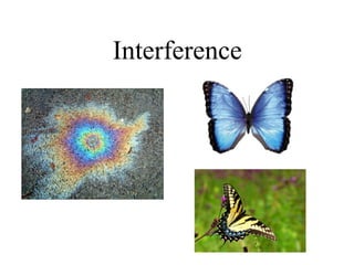
  • 2. Some more examples: Colours of hummingbirds neck and feathers Peacock feathers. Soap bubbles. What if you put two bulbs together In a room?
  • 3. Conditions for interference: (i) The light sources must be coherent. This means that the plane waves from the sources must maintain a constant phase relation. For example, if two waves are completely out of phase with φ = π , this phase difference must not change with time.
  • 4. Coherence: 1.Temporal Coherence: Correlation between field at a point at two different time : E(x,y,z,t1) and E(x,y,z,t2). If phase diff. Is constant over observation time, then it is temporal coherence. Tell how monochromatic a source is. 2.Spatial Coherence:When waves at different points in space preserve a constant phase difference over a time t. Temporal coherence is characteristic of single beam of light whereas Spatial Coherence is relationship between two separate beams of light.
  • 5. Conditions for interference: (i) The light sources must be coherent. This means that the plane waves from the sources must maintain a constant phase relation. For example, if two waves are completely out of phase with φ = π , this phase difference must not change with time. (ii) The light must be monochromatic. This means that the light consists of just one wavelength λ. (iii) The Principle of Superposition must apply.
  • 6. Stoke's law: According to this principle, in the absence of any absorption, a light ray that is reflected or refracted will retrace its original path if its direction is reversed.
  • 7.
  • 8. ar1 2 + at1 t2 = a Or t1 t2 = 1-r1 2 ar1 t1 + at1 r2 =0 Or r1 = - r2 According to the principle of optical reversibility, the two rays of amplitudes ar1 2 and at1 t2 must combine to give the incident ray.
  • 10.
  • 11. • Ray 2 undergoes a phase change of 180° with respect to the incident ray • Ray 1, which is reflected from the lower surface, undergoes no phase change with respect to the incident wave • Refracted waves don’t undergo phase transition. At interface, velocity and wavelength changes but frequency remains same.
  • 12. Thin Film Interference : Optical Path: • The optical path travelled by a light ray in a medium of refractive index 'μ' is not equal to actual path travel led by the light ray. Thin film planes can be parallel to each other or inclined. Interference in thin films can be studied under two categories, namely, 1.Interference in parallel plate film. 2.Interference in wedge-shaped films.
  • 13. Interference in parallel film due to reflected light: [AB=AD sin(i) = 2 AE sin(i) =2d tan(r). sin(i) =2d tan(r). µ sin(r)] Hence, Path diff. = 2µd [ 1/cos(r) – tan(r) sin(r)] = 2µd cos(r) Optical path diff. =µ(AC+CD)-AB BD is normal to AB = 2μd cos(r) −AB A C B DE 1 2 i r r i d air film air
  • 14. There is phase change of 180 or λ/2 for ray 1 whereas no phase change for ray 2. Therefore, The condition for maxima will be given by: 2µd cos(r)+ λ/2 = nλ 2µd cos(r) = (2n-1)λ/2 where n=1,2,3,......... Condition for minima will be given by : 2µd cos(r)+ λ/2 = (2n+1)λ/2 2µd cos(r) = nλ where n=0,1,2,3,.............. A C B DE 1 2 i r r i d air film air
  • 15. Interference in parallel film due to transmitted light: Optical path diff.= µ(CD+DE)-CP CQ is normal to DE and EP is normal to CT. ED is extended backward and it intersects extended CF at I.
  • 16. Interference in parallel film due to transmitted light: Z Y X S J K L ABZ = XCT (YZ || IX and AB || CT) PCE = 90-i, so CEP = i CDE = 2r, so DCQ = 90-2r, Hence QCE=r QDJ =CID=r CQ is normal to DE and EP is normal to CT. DE is extended backward and it intersects extended CF at I.
  • 17. Interference in parallel film due to transmitted light: Optical path diff. =µ(CD+DE)-CP So, optical path diff. = µ(CD+DE-QE) = µ(CD+DQ+QE-QE) = µ(CD+DQ) =µ(ID+DQ) = µ.IQ = 2µd.cos(r) μ= sin(i) sin(r) = CP/CE QE/CE = CP QE Hence, CP =µ. QE
  • 18. Conditions of maxima and minima in transmitted light are just reverse of conditions for reflected light. The condition for maxima will be given by: 2µd cos(r) = nλ where n=1,2,3,......... Condition for minima will be given by : 2µd cos(r) = (2n+1)λ/2 where n=0,1,2,3,......
  • 19. What if monochromatic source is replaced by white light?
  • 20. What if monochromatic source is replaced by white light? ➢ Path difference is function of μ which in turn depends on wavelength of incident light. ➢ Depending on region of film and viewing position, condition for maxima is satisfied for some wavelengths giving bright fringes. ➢ Wavelength for which minima condition is satisfied would be absent in pattern. ➢ That is why colours change when we change our viewing angle.
  • 21. Interference in Wedge shaped film : Surface GH and G1H1 inclined at an angle α enclose wedge shaped film. 90 r
  • 22. ● QB ⟂ G1 H1 and CQ⟂ GH, Hence  G1 OG =  BQC ●  BCQ = 180-(r+α), so  BZY = (r+α). ● YQ||DP, so  BZY =  ZPD=(r+α) ●  BZY =  YZC =  CDP ●  ABX =  XBF, so  FBD = 90-i 90 r O Y Z X 90 r
  • 23. Optical path diff. = μ(BC+CD)-BF =μ(BE+EC+CD)-BF sin(i)= BF BD ;sin(r)= BE BD μ= sin(i) sin(r) ;μ= BF BE BF=μ. BE 9 0 r O Y Z X r 90
  • 24. So, optical path diff. = μ(BE+EC+CD)-BF = μ(BE+EC+CD)-μ.BE =μ(EC+CD) =μ(EC+CP) =μ.EP =2μd cos(r+α) Due to reflection from denser medium a phase difference of 180o or λ/2 is introduced in ray BR. 9 0 r O Y Z X r 90
  • 25. For constructive interference or maxima : 2μd cos(r+α)+λ/2 = nλ where n=1,2,3....... 2μd cos(r+α) = (2n-1)λ/2 For destructive interference or minima : 2μd cos(r+α)+λ/2 = (2n+1)λ/2 where n=0,1,2,3....... 2μd cos(r+α) = nλ
  • 26. If this maxima is obtained at Xn from edge. For normal incidence, r=0 and assuming μ=1, d = Xn tan(α) So, 2 Xn tan(α) cos(α) = (2n-1)λ/2 2 Xn sin(α) = (2n-1)λ/2 (n+1)th maxima, 2 Xn+1 sin(α) = (2n+1)λ/2 2 (Xn+1 - Xn )sin(α) = λ or fringe spacing (Xn+1 - Xn ) = λ/(2.sin(α)) = λ/(2.α) Nth maximum will be given by : 2μd cos(r+α) = (2n-1)λ/2
  • 27. Newton's rings: A plano-convex lens is placed on plane glass sheet, an air film of increasing thickness is formed. Intereference occurs between ray 1 and 2 and circular fringes are formed. Ray 2 undergoes phase change of 180 when reflected from air to glass.
  • 28. Optical path diff. =2μd cos(r+α)+λ/2 For air film μ=1, for convex lens of large radius of curvature, α is very small and can be neglected. So, Optical path diff. =2d cos(r)+λ/2 For normal incidence r = 0, Optical path diff. = 2d +λ/2
  • 29. For bright fringe or maxima : 2d +λ/2 = nλ or 2d = (2n-1)λ/2 where n=1,2,3…. Condition for dark fringe: 2d +λ/2 = (2n+1)λ/2 or 2d = nλ where n=0,1,2,3.. Newton's rings will be observed for transmitted light as well with opposite conditions for minima and maxima.
  • 30. Diameter of Fringes : From property of circle : NP × NQ = NO × ND i.e. r × r = d(2R-d) =2Rd-d2 d <<R, r2 ≈ 2Rd d = r2 /2R For bright fringe: 2d = (2n-1)λ/2 2r 2 2 R = (2n−1)λ 2 ;Therefore ,r 2 = (2n−1)λ R 2 If D is diameter of the fringe ( r=D/2) then Dn=√2λ R√2n−1
  • 31. Similarly for dark fringe: 2d = nλ Or 2r 2 2 R =nλ;⇒r 2 =n λ R ⇒ Dn 2 =4nλ R⇒ Dn=2√nλ R Diameters of Newton's rings are proportional to square root of natural numbers.
  • 33. Visibility (V) = (I(max) - I(min))/(I(max) + I(min)) where I(max) represents the measured maximum intensity and I(min) is the corresponding minimum intensity. V will always lie between 0 and 1.
  • 34. Measurement of wavelenth: Dn 2 =4n λ R Dn+p 2 =4(n+ p)λ R Dn+ p 2 −Dn 2 =4 pλ R λ= Dn+ p 2 −Dn 2 4 pR If Dn and Dn+p gives diameter of nth and (n+p)th dark fringe respectively, then Therefore, λ can be calculated using this formula.
  • 35. Measurement of refractive index: Dn+ p 2 −Dn 2 =4 pλ R First Dn and Dn+p (diameter of nth and (n+p)th dark fringe respectively) is measured with air film in between : Without disturbing arrangement, liquid is poured in the conatiner. Again, D'n and D'n+p is measured Dn+ p 2 −Dn 2 =4 pλ R Dn+p ' 2 −Dn '2 = 4 p λ R μ Using above equations : μ= Dn+ p 2 −Dn 2 Dn+ p ' 2 −Dn '2 Diameter of rings reduces in liquid.
  • 36. Why the center of Newton’s rings appears dark in reflected light? The effective path difference between the reflected rays = 2μdcos(r+α)+λ/2. At the centre d=0 and for a very small angle of wedge cos(r+α) =1.Therefore effective path difference at λ/2. This is the condition of minimum intensity. Hence central spot of the ring system appears dark.
  • 37. Why an excessively thin parallel film appears black? In Thin parallel film, path diff. for reflected light: 2μdcos(r) + λ/2 For very thin film 2μdcos(r) << λ/2, so path diff. = λ/2 This is the condition of minimum intensity for all wavelengths. Therefore all wavelengths will be absent in reflected system, hence film will appear dark.
  • 38. Non-reflecting/Anti-reflecting Coatings: Non-reflective coatings admit more light into cameras and other optical instruments.
  • 39. Comparing the two reflected rays, there is no component of the phase difference due to reflection: these effects cancel out. Let's consider a wavelength λ in air and so a wavelength λglass in the glass. Now suppose that thickness of the layer is t = λcoating/4 = λ/4n. So the second reflected ray has travelled λcoating/2 further, so that the phase difference, entirely due to the path difference, is π.
  • 40. For this wavelength, we have destructive interference: very little power is reflected from the coating, and most is transmitted into the lens: more light is available for the optical instrument, and less is wasted in reflection. For optical instruments, one would usually choose λ to be in the middle of the visible spectrum (green light at around 550 nm). So, on the axis and with normal incidence, there is maximum destructive interference for green, but still considerable destructive interference for the rest of the visible spectrum.
  • 41. We've neglected the angle of incidence above. When the angle of refraction in the coating is θ, the pathlength difference is λ/(2n cos θ): longer by a factor of 1/cos θ. So the destructive interference is more complete for longer wavelengths – towards the red end of the spectrum – and the destructive interference is less complete for blue and violet. This explains why the lens in the photo above appears to havea blue-violet tinge – which provides a simple way of recognising such coatings.
  • 42.
  • 43. To obtain an interference pattern, there should be a definite phase relationship between the waves reflected from the upper surface of the film and from the lower surface of the film. Thus the path difference should be small compared to the coherence length. For example, if we are using the D1 line of an ordinary sodium lamp (l = 5.890 × 10⁻⁵ cm), the coherence length is of the order of 1 cm, and for fringes to be visible, D should be much less than 1 mm. There is no particular value of D for which the fringes disappear; but as the value of D increases, the contrast of the fringes becomes poorer. A laser beam has a very high coherence length, and fringes can be visible even for path differences much greater than 1 m. On the other hand, if we use a white light source, no fringes will be visible for D >~ 2 × 10⁻⁴ cm