SlideShare uma empresa Scribd logo
1 de 24
Baixar para ler offline
Unit Test DHR2000 Version 2.2 Page 1 of 24
Calibration Procedure
Unit Test Scientific Sdn. Bhd.
MALAYSIA
INSTRUCTION MANUAL FOR
UNIT TEST
COMPRESSION TEST
MACHINE
MODELS :
AD 200/EL & AD 300/EL
Semi-Auto & Manual Digital Type
(DHR 2000 V2.2)
Supply & Service by:
UNIT TEST SCIENTIFIC SDN BHD
No. 27 & 29, 3rd Floor,
The Highway Centre, Jalan 51/205,
46050 Petaling Jaya, Selangor, West Malaysia.
Tel : +603 7781 7585 / 7784 1843, Fax : +603 7781 7586
Email : info@unittest.com.my service@unittest.com.my
Website : www.unittest.com.my
Unit Test DHR2000 Version 2.2 Page 2 of 24
Calibration Procedure
Unit Test Scientific Sdn. Bhd.
MALAYSIA
Thank you for purchasing UNIT TEST compression test machine, quality Malaysian made product from UNIT
TEST SCIENTIFIC SDN. BHD. Being one of the pioneers & experienced testing equipment manufacturers,
UNIT TEST compression test machines have been exported worldwide for more than a decade ago. The
presence of UNIT TEST compression test machines can be felt throughout the world especially at the booming
modern construction projects, universities, testing laboratories, construction material factories, R & D centre’s,
colleges etc. The reliability, consistency & accuracy of the test results produced using UNIT TEST compression
test machine providing peace of mind to users.
For proper use of this machine, please read this manual carefully in order to ensure safe & correct operation.
Make sure only well trained & qualified personnel are allowed to operate this machine. Please refer to the
relevant test standard used for complete guide on making samples, testing method & interpretation of test
results.
Please fill in your company particular below :-
Company :
Telephone no. :
Email address :
Purchase date :
Remark :
Should you need parts replacement for this machine in the future or you need to purchase additional items,
please contact our office or your local agent.
Thank you for your continuous support.
Unit Test DHR2000 Version 2.2 Page 3 of 24
Calibration Procedure
Unit Test Scientific Sdn. Bhd.
MALAYSIA
CONTENTS
1 Introduction 4
2 Operating procedure 4
3 Advanced Options 5
3.1 Raw Data Setup 5
3.2 Data base Initialization 6
4 Equipment 7
4.1 Clear Logs 8
4.2 Print Option 8
5 Setting sample type 9
6 Setting the Base, Rate & %Fail 10
7 Transferring the test result from DHR 2000 to computer 11
8 Retrieve test result & print 12
9 Test precautions 13
10 Calibration and Setup 14
10.1 Transducer Calibration 14
10.1.1 Zero and Span Adjustment 14
10.1.1.1 Linearisation Adjustment 15
11 Calibration procedure 16
12 DHR 2000 display features 20
13 DHR 2000 keypad features 22
14 Specifications 23
15 Maintenance 23
16 Control panel diagram 24
Unit Test DHR2000 Version 2.2 Page 4 of 24
Calibration Procedure
Unit Test Scientific Sdn. Bhd.
MALAYSIA
1. INTRODUCTION
In construction industry, concrete plays a major role by becoming the main item to be used either in building or
highway projects. Concrete is a mixture of few materials such as cement, sand, aggregate, water, chemical etc.
The ratio of these materials being used will determine the strength of concrete to be produced. The quality of
concrete can be directly affected by its content mixed together. Therefore the quality of concrete must be
measurable in order to know the strength it can withstand for its relevant application. The ratio of the materials
used can then be controlled efficiently using UNIT TEST compression test machines.
2. OPERATING PROCEDURE
All procedures mentioned for semi-auto machine, except procedure for manual machine only in bracket ( )
1. Place a concrete sample onto the center of lower platen.
NOTE: Samples must be positioned exactly on the center of lower platen, using the guides provided on the platen. If the guides cannot support a particular
sample, draw lines on the platen so that the sample can be put at the center of the platen. Samples not positioned center enough may damage the upper ball
seating attached to the upper platen.
NOTE: Make sure the gap between the sample top surface & upper platen is not more than 15mm, as to avoid the machine piston from over traveled.
2. Close the safety fence.
3. Switch on the display & power pack by pressing the on/off switches.
4. Rotate the load release valve clockwise to stop the oil from flowing back to the tank.
NOTE: The load release valve must not be over-tightened, or its thread may damage. That’s why it’s advisable to rotate it using only 1 finger until it’s just
tight.
5. At the keypad, press MAN, ENTER TARE.
NOTE: If Weight & Reference need to be changed, after pressing MAN then move the arrow to Weight & Reference to change its value. Press ENTER after
changed. Then continue with ENTER & TARE.
6. Press the rapid approach switch continuously to raise up the sample to upper platen faster. When the sample
has just touches the upper platen, let go the rapid approach switch.
7. Rotate the speed controller clockwise (push the speed controller forward for manual machine) until the Base
value is achieved.
8. With reference to the +5% & -5% speed indicator bar, control the speed so that it is as near as possible to
the center of the bar.
9. When the sample is about to crushed, the motor will tend to slow down due to lots of strength at the sample
(ending stage). Increase the speed to the +5% side as far as possible.
10. Once the display shows “Now Printing, Please Wait”, rotate the load release valve anti-clockwise one round
to release the oil back to the tank.
11. Remove the crushed sample & clean the machine with brush or cloth.
12. Repeat the complete procedure to start a new test.
Unit Test DHR2000 Version 2.2 Page 5 of 24
Calibration Procedure
Unit Test Scientific Sdn. Bhd.
MALAYSIA
***ATTENTION LABORATORY SUPERVISOR***
These are the passcodes for ENG and SETUP. You may wish to remove this page
and keep in a safe place separate from the Instruction Manual to avoid
unauthorized adjustment of the calibration data.
Entry code for ENG key : 4298
3. ADVANCED OPTIONS
This chapter shows you how to tune your DHR2000 instrument in order to
operate effectively.
From the Main Screen (CHAPTER 2) press the ENG key to access these options. You will need to enter a
valid Pass code in order to be allowed. This pass code is given when the instrument is delivered and should
be stored in a safe place.
3.1 Raw Data Setup
Select each of the transducer to be programmed choosing the NEXT option as appropriate. The
display will show the current input reading (in Raw Divisions) so that any changes you make can
instantly be observed.
i. Filter this is a value that determines how many readings are taken to
average out noisy line. A value of 30 is recommended for most cases, but you can
determine the best setting by applying some load and changing the filter value.
Observe when the raw reading stops changing rapidly.
ii. Amplifier This is the gain to be applied to the signal received from the
transducer. To set it, select a value 01, 02, 04, 08, 16, 32 or 64 (other values are
accepted but internally they are always rounded off to one of the values indicated
above). Apply Full-Scale load and observe that the raw reading covers the expected
range. You may need to increase or decrease the Gain setting as appropriate.
The programmed values are also included in the Channel Calibration printouts described on
CHAPTER 10.
Unit Test DHR2000 Version 2.2 Page 6 of 24
Calibration Procedure
Unit Test Scientific Sdn. Bhd.
MALAYSIA
3.2 Data base Initialization
By choosing this option, you can reset your instrument to factory default values. It is divided into
initialization of metric (Init Metric) or imperial (Init Imperial). If you choose Init Metric, the
following happens: -
i. All memory logs are erased.
ii. Equipment Setup:-
Type: Compression
Units: Metric
Peak Hold? Yes
Query Abort? Yes
Show Proceed: No
Sensitivity: 10
SwitchOver: 002050 (kN)
Over load: 002020 (kN)
*Custom Details *Back
iii. New Test Setup:-
Stage: 01/02
Index: AAAAAA
Reference: 000001
%Fail: 20
Type: Compression
Base: 0010.0 (kN)
Rate: 0006.0 kN/s
Target: 0000.0 (kN)
*Taring Conditions*
*Clear TARE*
*Sample*
*Back*
iv. Transducer Input defaults.
These fields are not altered. This means that your Calibration and Linearisation data is
preserved. The only way to change this is by recalibrating again.
Unit Test DHR2000 Version 2.2 Page 7 of 24
Calibration Procedure
Unit Test Scientific Sdn. Bhd.
MALAYSIA
4. EQUIPMENT
There are a number of features, which can be configured to suit your installation or preferences. This
option can be selected via SETUP key followed by option 3.
i. Units? Select Metric or Imperial. The units used will change
between kN and Lbf, mm and in, MPa and PSI.
ii. Peak Hold? Select YES to freeze the display of the maximum load
detected during a test, or NO if this is not required. Note
that this option affects only the display on the Main Screen.
iii. Query Abort? Select YES to make sure that a warning is given
whenever a test is aborted (pressing the ABORT key)
manually. This can help to prevent ending a test
inadvertently. Otherwise, select NO.
iv. Sensitivity? Enter the percentage error measured while a test is running
that will fill the error box shown on the Main Screen (CHAPTER 2). Usually the
%Error Band is 05, but note that entering a value of 00 will effectively prevent the
box from being shown.
v. SwitchOver: Enter the loading level at which the instrument will
automatically switch from the Range to the HIGH transducer ranges. This is
applicable to Compression Tests only.
vi. Over load: To prevent the frame being damaged by applying a large
loading, you can define a level above which the instrument giving a long bleep,
indication that the machine is overloaded. You have to switch off the power
switch immediately.
vii. *CUSTOMISE* You can define text to appear as Headers and Footers in all
printouts available (Test Results and Transducer Calibration). Enter for example a
description or your Company’s name, Customer details, etc.
viii. *TARE* You define here the parameters to be used during the
Taring Stage of a test execution – see CHAPTER 3.
Maximum This is the maximum loading that will be allowed to be tared. If the
level is exceeded when a test is tared, the test will be aborted.
Unit Test DHR2000 Version 2.2 Page 8 of 24
Calibration Procedure
Unit Test Scientific Sdn. Bhd.
MALAYSIA
4.1 Clear Logs
This will erase the non-volatile memory, removing the results of any previous tests carried out by your
DHR2000 instrument.
A warning will be presented first, to avoid erasing data inadvertently. You can choose to proceed or to
cancel the request.
4.2 Print Option
1. Data and Summary
2. Data Only
3. Summary Only
4. Back
Unit Test DHR2000 Version 2.2 Page 9 of 24
Calibration Procedure
Unit Test Scientific Sdn. Bhd.
MALAYSIA
5. SETTING SAMPLE TYPE
To access to sample type selection, press the DP TEST key. Press the up/down keys () to select for
SAMPLE & press ENTER. Display will show the following samples selection :-
1. Standard cylinder
2. Standard Cube
3. Non Stdrd Cylinder
4. Non Stdrd Cube
5. Beam Block
6. Special Area
1. Standard Cylinder : Press key no. 1. For example if the sample to be tested is
a 150mm  x 300mm height standard , move the arrow to Diam. & press
ENTER. Press the up/down keys to select 0150 & press ENTER. Move the
arrow to Length & press ENTER. Press the required Length of 0300 & press
ENTER. Then press ABORT to exit.
2. Standard cube : Press key no. 2. For example if the sample to be tested is a
150mm standard cube, move the arrow to Cube & press ENTER. Press the
up/down keys to select 0150 & press ENTER. Then press ABORT to exit.
3. Non Stdrd Cylinder : Press key no. 3. For example if the sample to be tested
is a 151mm  x 303mm height non-standard cylinder, move the arrow to
Diam. & press ENTER. Press the required diameter of 0151 & press ENTER.
Move the arrow to Length & press ENTER. Press the required length of
0303 & press ENTER. Then press ABORT to exit.
4. Non Stdrd Cube : Press key no. 4. For example a cube sample may have
measured dimensions of non-standard width 151mm, length 152mm & depth
153mm. Move the arrow to Width, Length & Depth & key in the required
dimensions accordingly. Then press ABORT to exit. Please refer to the
following cube diagram of the actual position to be put into the machine :
Width
Depth
Length
5. Beam Block : Press key no. 5. For example the beam sample may have
dimensions as in the diagram below :-
Unit Test DHR2000 Version 2.2 Page 10 of 24
Calibration Procedure
Unit Test Scientific Sdn. Bhd.
MALAYSIA
500mm
100mm
100mm
Move the arrow key to Width & press ENTER. Press the required width of 0100 & press ENTER. Move the
arrow to Length & press ENTER. press 0300 & press ENTER. The Length is the distance between the bottom
rollers of flexural machine of 300mm apart for this beam size, not the length of the beam sample. (for 150 x
150 x 750mm beam, the bottom roller distance is 450mm) Move the arrow to Depth & press ENTER. Key in
the required 0100 & press ENTER. Then press ABORT to exit.
NOTE : Do not enter the sample Weight at this part. The Weight can be entered easily during the
Manual operation. Please refer to the Manual operating procedure.
6. SETTING THE BASE, RATE & % FAIL
The Base, Rate & % Fail features can be accessed by pressing the DP TEST key & if necessary to change, make
sure the correct Sample is selected first. For example to set the Rate at 6.8kN/s, press the DP TEST key & move
the arrow to Rate & press ENTER. Press 0068 & press ENTER to confirm. Follow the same procedure to set for
Base & % Fail if required. Refer to DHR 2000 display features (CHAPTER 12) for further explanation on
these 3 features.
Unit Test DHR2000 Version 2.2 Page 11 of 24
Calibration Procedure
Unit Test Scientific Sdn. Bhd.
MALAYSIA
7. TRANSFERING THE TEST RESULT FROM DHR 2000 TO COMPUTER
1. Use an optional RS232 serial cable of 25 pin male (to display) & 9 pin female (to computer) commonly
known as modem cable.
2. Follow the below setting in computer prior to transfer data from DHR 2000 display :
3.
Start
Accessories
Create shortcut on desktop
to skip these steps Communications
Hyperterminal
Enter file name & click OK
Enter Com 1 or Com 2 & click OK
Bits per second : 9600
Data bits : 8
Parity : None
Stop bits : 1
Flow control : Xon/Xoff
Click Apply & OK
4. Transfer options :
a) Transfer automatically test detail after each test
-computer is set & connected to computer during testing or
b) Transfer later after testing
-select test detail by pressing key no.2 or test summary by
pressing key no.3. Then press ENTER to select Print option to
transfer the test results to PC. Press up/down keys to select test
detail page to transfer.
5. 'Save As' to any desired folder & location after transferring.
6. To open in Microsoft Excel for graphical representation or analysis, double click on Excel icon, select
Open, Files of type : All Files & select the saved hyperterminal file. The data in Excel format may look
a little messy, so some amendment is necessary.
NOTE : Depending on the size of data stored, the DHR 2000 memory will become full. If this happen then press key no. 7, press passcode 4298, press ENTER,
press key no. 3 to select Clear Logs & press ENTER to clear all test result in the memory.
NOTE : Passcode shall be kept confidential by superior or manager in charge, to avoid unauthorised changes.
NOTE : If unable to transfer, switch the position of the orange & grey wire at the DHR electronic board connector.
Unit Test DHR2000 Version 2.2 Page 12 of 24
Calibration Procedure
Unit Test Scientific Sdn. Bhd.
MALAYSIA
8. RETRIEVE TEST RESULT & PRINT
The DHR 2000 display is also able to connect to certain printers by using an optional RS232 serial cable of both
sides 25 pin male. Some examples of A4 paper printers that can be connected such as Panasonic KX-P1131 &
Epson LQ-300+. Please note that the Epson printer needs to be set to correct baud rate of 9600, 8 data bits &
None parity before it can be used.
Another commonly used is the Star SP700 mini printer which uses 76mm paper rolls. The only setting for this
printer is to off the dip switch no.4 located at the
bottom of the printer (remove the steel cover using a '+' screwdriver & total of 10
dip switches can be seen) To print during testing, simply connect & on the printer. It will print the test detail
immediately after sample crushed. To print the test detail or summary anytime after test, follow the simple
procedure as below :-
NOTE : The 2 A4 printers mentioned above have been used by our customers. There may be other
compatible printers in the market can be tried, as long as the printers have serial port. But printers with
both serial & parallel ports are slowly obsolete in the market due to its low demand. Another alternative
will be the 76mm paper roll mini printer as mentioned above.
A) PRINTING TEST DETAIL (1 TEST PER PAGE)
1. Press key no. 2.
2. Press the up/down keys to select for the desired page.
3. Press ENTER.
4. Press key no. 1 to select PRINT. Now the printer will start printing the test detail.
5. Press ABORT twice to exit from the test detail after finish printing.
B) PRINTING TEST SUMMARY (10 TEST PER PAGE)
1. Press key no. 3.
2. Press the up/down keys () to select for the desired page.
3. Press ENTER.
4. Press key no. 1 to print all tests.
5. Press ABORT twice to exit from the test summary after finish printing.
Unit Test DHR2000 Version 2.2 Page 13 of 24
Calibration Procedure
Unit Test Scientific Sdn. Bhd.
MALAYSIA
9. TEST PRECAUTIONS
1. Before testing of concrete samples, make sure the following settings are
correct according to the requirement of the relevant samples to be tested :
Compression mode, Base, Rate, %Fail, sample type (Standard Cylinder or
Standard Cube) & Dimensions (Width, Depth & Length).
2. The best clearance between the sample & upper platen should be
about 10mm. It should not exceed 25mm. Clearance that is bigger than
25mm will cause the piston to be over travel which may damage the piston &
cylinder. To solve this problem, use the suitable thickness of distance piece
or you may order from Unit Test Scientific or your local agent.
3. For testing of concrete cylinders, make sure both ends of the cylinder are
being capped evenly as required by the standard. Cylinders that are not
capped have uneven surface that may damage the machine alignment.
4. For testing of concrete cubes, make sure the uneven surface is facing out
(facing the machine operator) & only very flat surface touches both upper &
lower platens.
5. Always keep the machine in clean condition after use.
6. Not suitable to test block samples, as it may damage the component
part of top platen & causing machine alignment problem. (Please
enquire for block testing machine)
7. Should the voltage supplied to the machine is fluctuating (not stable), use a
voltage regulator or stabilizer connecting to the machine. Unstable voltage
will damage the machine digital part.
8. Always position the sample on the center of lower platen using the guides or
lines provided. Sample that is out of the center can damage to machine
alignment.
9. Not suitable for testing of smaller samples such as 50mm mortar cube or
40x40x160mm mortar prism. A smaller capacity & more precise machine shall
be used.
10.DURING EMERGENCY, SWITCH OFF THE MACHINE IMMEDIATELY &
RELEASE THE MANUAL LOAD RELEASE VALVE.
Unit Test DHR2000 Version 2.2 Page 14 of 24
Calibration Procedure
Unit Test Scientific Sdn. Bhd.
MALAYSIA
10. CALIBRATION AND SETUP
This chapter shows you how to operate DHR2000 instrument in order to set it up to run efficiently.
From the Main Screen (CHAPTER 10), press the SETUP key to access these options. You will need to enter
a valid Passcode in order to be allowed. This passcode is given when the instrument is delivered and should
be stored in a safe place.
10.1 Transducer Calibration
*** IMPORTANT ***
During calibration operation, you can control the applied load by operating the external
Speed Control Pot.
Note also that your DHR2000 instrument processes the electronic signals received from
the transducers according to the Filtering and Amplification parameters defined in
CHAPTER 5.
10.1.1 Zero and Span Adjustments
i. First of all select the transducer Range or FLEXURAL range by positioning the cursor next to the
channel identification line and then pressing the ENTER key until the required one is shown.
ii. Next select the Scale field and enter the required load value at Full Scale, normally 2000 (HIGH)
sometimes maybe 1500, 3000, 4000 or 5000 and depends on machine capacity and 100 (FLEXURAL)
kN respectively.
iii. Select and activate the *CLEAR* option to start a new calibration. You will be warned about the
implications of clearing calibration data previously stored. You can then choose to proceed or not.
iv. Make sure that the oil valve is closed, the fast pump is off and no load is currently being applied with
Speed Control Pot is set to give a steady oil flow rate. When the readings are stable, and the platen is off
the seating position, select the *ZERO* option. The transducer reading should now show 0000.0, and
the field labeled Zero will display the offset measured at this time.
v. Now start the fast pump to close the day light and then switch off the fast pump. Slowly apply the load
until the Full Scale level has been reached. Maintain the load using the Speed Control Pot so that the
readings are stable, and then select the *GAIN* option. The transducer should now show the same value
as that configured on the Scale entry (step ii above), and the field labeled Gain will display the raw
transducer divisions at this point.
Unit Test DHR2000 Version 2.2 Page 15 of 24
Calibration Procedure
Unit Test Scientific Sdn. Bhd.
MALAYSIA
vi. Open the oil valve to release the loading. The first stage of a transducer calibration is now complete.
vii. Repeat the above procedure from iii to vi for Range and FLEXURAL range where applicable.
10.1.1.1 Linearisation Adjustments
The DHR2000 instrument allow you define an interpolation table of up to 20 points for each channel to
correct small variations in transducer linearity throughout the complete measuring range.
Each table entry consists of an Expected reading and the corresponding measured value. You move
between entries by using the arrow keys. Select a field for editing by pressing the ENTER key. Note that
not all entries need to be used.
i. Apply the load manually until the Expected loading is achieved.
ii. Enter the Measured field. You can either:-
 Make a note of the transducer reading displayed at the bottom of the screen and copy it into the
Measured Column, or
 Press the TEST key to let DHR2000 do this automatically for you. Note that this wills only works if
the transducer reading is within +/- 5% of the expected value, otherwise the instrument reject the
option.
iv. Continue with all table entries as above. Press the ABORT key to end the
adjustments and return to the previous screen.
Unit Test DHR2000 Version 2.2 Page 16 of 24
Calibration Procedure
Unit Test Scientific Sdn. Bhd.
MALAYSIA
11. CALIBRATION PROCEDURE
All UNIT TEST compression testing machines have been calibrated in the factory using our load cells.
However once it arrives in your country, the machine may experience slight inaccuracy due to transportation,
different load cell used & environment. You should have your machine calibrated by your local authority once
the machine has been put at your permanent place. Make sure the machine is placed onto a flat & level cement
or concrete surface to prevent from unstable force distribution during crushing that may contribute to doubts.
UNIT TEST compression testing machines can be calibrated easily & adjustment to desired accuracy can be
fine-tuned easily through its user friendly calibration function, even after long term of usage. Please read &
follow the simple procedures before attempting to perform calibration on this machine
Very importantly, calibration devices (load cell or load column) used must be positioned as center as
possible on the machine lower platen. Use a ruler or caliper to position the device on the lower platen so
that all distance a, b, c & d are the same :-
Load cell that is not positioned on the center of lower platen may damage the machine alignment & can cause
inconsistent readings.
A) CHECKING THE INITIAL ACCURACY
1. Place the load cell (or proving ring, load column or other suitable capacity of force measuring devices)
on the center of lower platen.
2. Make sure the clearance between load cell & upper platen is not more than 25mm. If the clearance is too
much, add suitable thickness of distance piece to reduce to the smallest possible clearance. If still unable
to reduce, place flat hardened steel onto the load cell.
NOTE : Clearance more than 25mm will probably cause the machine piston to be over-traveling & may damage the piston & cylinder. The ideal clearance
between the load cell & upper platen will be about 10mm
3. Switch on the machine & press MAN, ENTER, TARE. Close the machine load release valve.
4. Press the rapid approach switch & watch the load cell moving up fast to the upper platen.
Unit Test DHR2000 Version 2.2 Page 17 of 24
Calibration Procedure
Unit Test Scientific Sdn. Bhd.
MALAYSIA
5. When the load cell almost touches the upper platen, release the rapid approach switch.
6. Operate the manual speed controller until the desired 1st
reading of calibration force shown at load cell
(e.g. 400kN) & immediately decrease the machine speed to hold the pressure.
NOTE : BS EN 12390-4:2000 requires calibration starting at 20% of the machine capacity then upwards of at least 5 equip-spaced forces. Example for
2000kN machine, forces to be calibrated are 400kN, 800kN,1200kN, 1600kN, 2000kN. But if testing condition requires calibrating below 400kN, then
additional small capacity device shall be used (e.g. 500kN load cell) to calibrate 100kN, 200kN & 300kN.
NOTE : When the load cell almost reaches the desired force, slow down the speed controller so that the reading can be hold easily.
7. Record the reading shown on the machine display (e.g. maybe 404kN)
8. Repeat the control of manual speed controller to apply force onto the load cell, until the load cell shows
the second required calibration value (e.g. 800kN) & record the value immediately shown on machine
display (e.g. maybe 811kN)
9. Repeat the whole applying force to load cell & recording the machine reading for the rest of the
calibration forces.
10. Below is an example of machine’s initial accuracy :
Applied force at load cell (kN) Machine reading (kN) % Error
400 410 2.50
800 809 1.13
1200 1177 -1.92
1600 1633 2.06
2000 1965 -1.75
NOTE : % Error = Machine reading – Applied Force x 100
Applied force
B) ENTERING THE LOAD CELL VALUE TO RANGE SCALE
Depending on reference test standard, certain % error that is out of tolerance is not acceptable (e.g. the error for
400kN is 2.50% which is out of ± 1.0% error requirement for Class 1 machine).If adjustment is necessary, it’s
better to clear all the factory calibrated values by following the below procedure.
NOTE : But if all the % errors are acceptable, no adjustment is needed.
NOTE : It is recommended to perform the procedure in this PART B if the errors recorded are about 3% & above because it is difficult to correct the error
for each force as mentioned in PART D. Otherwise if the errors are 3% & below, skip PART B & C to proceed to PART D to adjust minor errors in the
Linearisation section which has already been entered in factory.
1. Press key no. 7.
2. Press passcode 4298.
3. Press key no. 1 to select Calibration. Now the screen is at Range I/P.
4. Press the up/down key ( ) to move the arrow () to Clear Scale & press ENTER.
5. Press ENTER again to confirm clearing all calibration data.
6. Re-enter the Scale as 2000 kN.
7. Move the arrow to Set Zero & press ENTER.
Unit Test DHR2000 Version 2.2 Page 18 of 24
Calibration Procedure
Unit Test Scientific Sdn. Bhd.
MALAYSIA
8. Press ENTER again to confirm clearing the initial load value.
9. Move the arrow to Set Gain. (DON’T PRESS ENTER YET)
10. Close the machine load release valve.
11. Operate the machine until the load cell showing 2000kN & immediately hold the pressure.
12. Press ENTER (the arrow already at Set Gain)
13. Press ENTER again to confirm entering the 2000kN scale to transducer.
14. Open the load release valve.
NOTE : At Range, Scale must be 2000Kn, Scale is machine capacity. (E.g. if machine is 2000kN capacity, then Scale is 2000kN & if machine is
3000kN capacity, then Scale is 3000kN) If the Scale at ranges is not correct, then key in the right scale accordingly.
15. Press ABORT to exit to setup menu & press ABORT again to exit to main screen.
C) CHECKING THE ACCURACY AFTER ENTERED THE LOAD CELL VALUE & LINEARISE
(MINIMISE) THE ERRORS
Repeat the whole procedure as in PART A to check the accuracy again for the desired forces. The result may
look like the following example :
Applied force at load cell (kN) Machine reading (kN) % Error
400 404 1.00
800 809 1.13
1200 1211 0.92
1600 1618 1.13
2000 1978 -1.10
As shown in the result, there may be slight error even after enter the load cell value which is normal. If you are
satisfied with the results, no adjustment is needed.If adjustment is necessary reduce the forces to less than
±1.0%, please proceed to the following procedure:
1. At main screen, press key no. 7.
2. Press passcode 4298.
3. Press key no. 1 to select Calibration.
4. Move arrow to Range.
5. Move arrow to Linearisation & press ENTER.
6. Key in all the calibration results as illustrated in the example above as follows :-
Unit Test DHR2000 Version 2.2 Page 19 of 24
Calibration Procedure
Unit Test Scientific Sdn. Bhd.
MALAYSIA
No. Expected Measured
01 000400 000404
02 000800 000809
03 001200 001211
04 001600 001618
05 002000 001978
06 000000 000000
07 000000 000000
08 000000 000000
09 000000 000000
10 000000 000000
7. After key in all the forces above, press ABORT to exit to setup menu & press ABORT again to exit to
main screen.
D) CHECKING THE ACCURACY AFTER LINEARISATION & CORRECTING MINOR ERRORS
Repeat the whole procedure as in PART A to check the accuracy again for the desired forces. The
LINEARISED result may look like the following example :
Applied force at load cell (kN) Machine reading (kN) % Error
400 401 0.25
800 799 -0.25
1200 1205 0.42
1600 1617 1.06
2000 1977 -1.15
Although Linearisation has been done, it sometimes may or may not adjusting the machine reading to be the
same as the applied force perfectly. As shown in example above, the errors at 1600kN & 2000kN already
exceeded ±1.0%. Again if the results are satisfying, no adjustment is necessary. But if it’s a requirement for
errors to be ±1.0% or less, then a minor adjustment should be done as follows:-
1. Enter into the Linearisation page in Range by following the procedure as in PART C (step 1 to step 5)
2. Press the up/down key ( ) to move the arrow () to “1618”kN at the “Measured” section.
3. Since there is an error of 17kN (machine reading 1617kN – applied force 1600kN), you need to add this
17kN error to the force “1618”kN at the “Measured” section. Press ENTER & change the reading to
1635kN. Press ENTER again.
4. Press the up/down key ( ) to move the arrow () to “1978”kN at the “Measured” section.
5. Since there is an error of -23kN (machine reading 1977kN-applied force 2000kN), you need to deduct
this 23kN error from the force “1978”kN at the “Measured” section. Press ENTER & change the reading
to 1955kN. Press ENTER again.
6. Press ABORT twice to exit to the main screen.
7. Now repeat the whole procedure as in PART A to take another series of force readings. Now all the
errors should be minimized to within ±1.0%.
Unit Test DHR2000 Version 2.2 Page 20 of 24
Calibration Procedure
Unit Test Scientific Sdn. Bhd.
MALAYSIA
11. DHR 2000 DISPLAY FEATURES
1. Force value : Displaying the current force value in kN. It will increase accordingly when pressure is
applied to the machine piston.
2. Speed indicator bar : Indicates the current loading speed according to the set Rate. To be controlled by
user manually.
3. Status : Loading status of the machine, either Ready (not operating), Started (operating), or Finish
(Sample crushed, machine has stopped)
4. Peak : Is the maximum force achieved after the sample has crushed.
5. Date & Time : Showing the current date & time. Only need to set once.
6. Reference : Showing the test number. It will increase in sequence by itself if not set.
7. Base : When set at 10kN, the speed indicator bar will start to show only when the load reaches 10kN in
order to eliminate initial unstable speed caused by deadweight. (Factory default & recommended Base is
10kN. The minimum sample failure value should not be less than the Base value. For example if the
sample crushed at 8.6kN, then the Base must be set at 5kN. The Rate set must be less than the Base
value. For example if the rate is set at 12kN/s, then the Base must be set at 15kN or 20kN))
8. Rate : User preset loading speed in kN/s. Must be set according to sample's test standard.
9. % Fail : Preset percentage of damage at the concrete sample in order for the machine to inform the user
to stop the operation. (see Note below)
Unit Test DHR2000 Version 2.2 Page 21 of 24
Calibration Procedure
Unit Test Scientific Sdn. Bhd.
MALAYSIA
10.Tare : Temporary storage for the initial tared (zeroed) force value upon starting of operation. Not
adjustable.
11.Standard cube : Preset sample type (standard or non-standard cube, standard or non-standard cylinder,
beam block & special area)
12.Dimensions : Description of sample dimension (width, depth & length)
13.Sample size : Measurement of sample dimensions in mm.
14.Area : Area of sample surface that is in contact with upper platen.
15.Stress : Auto calculation of concrete strength in Mpa obtained from the peak value & Area.
NOTE : The following diagram is an example of preset % Fail
10% 20% 40%
Factory preset for % Fail is 15% to 20%. But if the sample damages too much or explodes before the machine
informs to stop, reduce the % Fail. But the % Fail should not be set too low causing the machine to inform even
before the sample reaches its maximum strength. There is no standard guideline for % Fail & if it’s necessary to
reduce it, trial & error for the same samples few times as illustrated at the graph below :-
Strength (Mpa)
Maximum
strength achieved
even before the machine
inform the user to stop
% Fail
The minimum % Fail must be determined so that the machine will stop only after maximum strength is
achieved. It may vary for different sample types.
Unit Test DHR2000 Version 2.2 Page 22 of 24
Calibration Procedure
Unit Test Scientific Sdn. Bhd.
MALAYSIA
13. DHR 2000 KEYPAD FEATURES
Key features :
1. DP, TEST - Change Compression / Flexural mode, Base, Rate, % Fail & Sample type.
2. 0 (TARE) - To tare off (zero) any initial value during beginning of test.
3. HELP - Simple explanation on Channel Calibration (refer to instruction manual for detail explanation)
4. 1 (CLOCK) - Adjust the Time & Date
5. 2 (PRINT) - Show 1 test result in detail per page. Press the  keys to view the previous result. Press
ENTER & select PRINT to print or transfer the result to computer.
6. 3 (SUM) - Show 10 test results in summary per page. Press the  keys to view the previous 10 results.
Press ENTER & either select PRINT (to print / transfer the current page only) or PRINT ALL (to print
transfer the first until the last result)
7. 4 (SCR) - Press to zoom the display bigger. Press again to return to original size.
8. 5 – No function
9. 6 (SOL) – No function
10. 7 (SETUP) - Calibration setup (confidential password required), overload trigger & clear memory. (FOR
CALIBRATION USE ONLY)
11. 8 – No function
12. 9 (ENG) - Raw data to amplify the transducer value & PID control for automatic setup of motor speed &
parameter. (FOR FACTORY & CALIBRATION USE ONLY)
13.  - For moving the arrow cursor up or down
14. MAN () - For machine operation in Manual mode. Press MAN (change the Reference, Weight etc. if
required), ABORT & TARE (TARE must be pressed for all manual modes) Also for moving the arrow
cursor up or down.
Unit Test DHR2000 Version 2.2 Page 23 of 24
Calibration Procedure
Unit Test Scientific Sdn. Bhd.
MALAYSIA
15. ENTER - Press ENTER to change a data & ENTER again to fix the data after changing.
16. ABORT - Exit from a setting or page in the screen. Also use to cancel the machine operation at any time
during testing.
14. SPECIFICATIONS
1. 2 channel programme (Compression mode 0.1 kN resolution & Flexural mode 0.01 kN resolution)
connectable to 2 machine frames with 1 controller.
2. Storage of test results in memory & transferring of data to computer or printer.
3. Large 75 x 125mm clear LCD display c/w zoom function.
4. User input of loading Rate for manual controls of testing speed.
5. Sample type, size & weight selectable for auto calculation of Mpa & Density.
6. User friendly operation with simple & clear page by page instruction.
7. Calibration c/w passcode protection & accuracy adjustment system (linearisation) for achieving ±1.0%
accuracy over the whole calibrated range.
8. User input of testing limit (overload) in kN for automatic alarm trigger.
9. Machine frame built to be tough, long lasting & providing very consistent test results. Used for testing
various sizes & types of standard concrete samples.
10. Power : 240V, 50Hz, 1ph
15. MAINTENANCE
1. There is virtually very minimal maintenance for this machine. However it is very important that the user
follow each & every correct operating procedure to ensure this machine is always in perfect working
condition.
2. Pay attention to the Precaution section especially on the positioning of samples, testing smaller samples,
piston traveling limit, etc.
3. Inspect the top & bottom platen for wear by checking its flatness to observe if they are dented.
4. This machine only use hydraulic oil grade 68, which should be changed ideally once a year. The oil level
should be always full. Open the nut of the square oil tank located at bottom of power pack. Insert your finger
into the oil tank. If you can touch the oil, it’s full. If you can’t touch, then you need to top up.
5. Occasionally check if the protective rubber cover does not tear off causing oil leakage. Before changing a
new rubber cover, replace with new hydraulic oil grade 68.
6. It is a normal National Standard requirement to request for calibration at least once a year, after relocating the
machine or repair which is likely to affect the machine accuracy.
Unit Test DHR2000 Version 2.2 Page 24 of 24
Calibration Procedure
Unit Test Scientific Sdn. Bhd.
MALAYSIA
16. CONTROL PANEL DIAGRAM
Rapid Approach Switch (2)
Power Switch (1)
Key
Speed Controller (4)
Load Release Valve (3)
Power Switch (1)
Key
Speed Control Knob (5)
Speed Control Lever (4)
Load Release Valve (3)
Oil Tank
Nut
Inlet
Outlet
Rapid Approach Switch (2)

Mais conteúdo relacionado

Destaque

Yanmar diesel generator operation manual
Yanmar  diesel generator operation manualYanmar  diesel generator operation manual
Yanmar diesel generator operation manual
Manuel Sotelo
 
Rapid compression machine_monthly meeting
Rapid compression machine_monthly meetingRapid compression machine_monthly meeting
Rapid compression machine_monthly meeting
Nathan Loveldi
 
Principle of DC Generator
Principle of DC GeneratorPrinciple of DC Generator
Principle of DC Generator
guest60b26e
 
Universal testing machines
Universal testing machinesUniversal testing machines
Universal testing machines
Shivam Tiwari
 
Service Operation Management_Maruti
Service Operation Management_MarutiService Operation Management_Maruti
Service Operation Management_Maruti
Ankit Suneja
 

Destaque (11)

Alfanar Generator Assessment Process
Alfanar Generator Assessment ProcessAlfanar Generator Assessment Process
Alfanar Generator Assessment Process
 
2002 MAXIMA OWNER'S MANUAL
2002 MAXIMA OWNER'S MANUAL2002 MAXIMA OWNER'S MANUAL
2002 MAXIMA OWNER'S MANUAL
 
Yanmar diesel generator operation manual
Yanmar  diesel generator operation manualYanmar  diesel generator operation manual
Yanmar diesel generator operation manual
 
ICE Vibratory Hammer Owners Manual
ICE Vibratory Hammer Owners ManualICE Vibratory Hammer Owners Manual
ICE Vibratory Hammer Owners Manual
 
Final
FinalFinal
Final
 
Roller compaction machines
Roller compaction machinesRoller compaction machines
Roller compaction machines
 
Rapid compression machine_monthly meeting
Rapid compression machine_monthly meetingRapid compression machine_monthly meeting
Rapid compression machine_monthly meeting
 
Principle of DC Generator
Principle of DC GeneratorPrinciple of DC Generator
Principle of DC Generator
 
Universal testing machines
Universal testing machinesUniversal testing machines
Universal testing machines
 
Service Operation Management_Maruti
Service Operation Management_MarutiService Operation Management_Maruti
Service Operation Management_Maruti
 
dc Generator Ppt
dc Generator Pptdc Generator Ppt
dc Generator Ppt
 

Semelhante a Instruction manual for dhr v2.2

Training Outline HMLS Auto Calcimeter
Training Outline HMLS Auto CalcimeterTraining Outline HMLS Auto Calcimeter
Training Outline HMLS Auto Calcimeter
Michael Crum
 
Jcb 8027 z mini excavator service repair manual sn898000 onwards
Jcb 8027 z mini excavator service repair manual sn898000 onwardsJcb 8027 z mini excavator service repair manual sn898000 onwards
Jcb 8027 z mini excavator service repair manual sn898000 onwards
jkmsedopl
 
JCB 8032Z MINI EXCAVATOR Service Repair Manual SN899000 Onwards
JCB 8032Z MINI EXCAVATOR Service Repair Manual SN899000 OnwardsJCB 8032Z MINI EXCAVATOR Service Repair Manual SN899000 Onwards
JCB 8032Z MINI EXCAVATOR Service Repair Manual SN899000 Onwards
jknjekmds
 
Jcb 8032 z mini excavator service repair manual sn899000 onwards
Jcb 8032 z mini excavator service repair manual sn899000 onwardsJcb 8032 z mini excavator service repair manual sn899000 onwards
Jcb 8032 z mini excavator service repair manual sn899000 onwards
jkmsedopl
 
Jcb 8027 z mini excavator service repair manual sn898000 onwards
Jcb 8027 z mini excavator service repair manual sn898000 onwardsJcb 8027 z mini excavator service repair manual sn898000 onwards
Jcb 8027 z mini excavator service repair manual sn898000 onwards
fjjskedmmemm
 
QUICKREFSeries2000 w links
QUICKREFSeries2000 w linksQUICKREFSeries2000 w links
QUICKREFSeries2000 w links
John Dettinger
 
Parker Kittiwake - Parker-branded Product Overview
Parker Kittiwake - Parker-branded Product OverviewParker Kittiwake - Parker-branded Product Overview
Parker Kittiwake - Parker-branded Product Overview
Parker Kittiwake
 

Semelhante a Instruction manual for dhr v2.2 (20)

Viscometer model 900
Viscometer model 900Viscometer model 900
Viscometer model 900
 
Pf700 energy savings_lab
Pf700 energy savings_labPf700 energy savings_lab
Pf700 energy savings_lab
 
Digital viscometer
Digital viscometer Digital viscometer
Digital viscometer
 
Hm 5750 manual-0817
Hm 5750 manual-0817Hm 5750 manual-0817
Hm 5750 manual-0817
 
Hitachi Zaxis ZX140-3 Zx310 Excavator Service Manual.pdf
Hitachi Zaxis ZX140-3 Zx310 Excavator Service Manual.pdfHitachi Zaxis ZX140-3 Zx310 Excavator Service Manual.pdf
Hitachi Zaxis ZX140-3 Zx310 Excavator Service Manual.pdf
 
Hitachi Zaxis ZX450-3 Zx870 Excavator Service Manual.pdf
Hitachi Zaxis ZX450-3 Zx870 Excavator Service Manual.pdfHitachi Zaxis ZX450-3 Zx870 Excavator Service Manual.pdf
Hitachi Zaxis ZX450-3 Zx870 Excavator Service Manual.pdf
 
Hitachi Zaxis ZX70-3 to Zx350 Excavator Service Manual.pdf
Hitachi Zaxis ZX70-3 to Zx350 Excavator Service Manual.pdfHitachi Zaxis ZX70-3 to Zx350 Excavator Service Manual.pdf
Hitachi Zaxis ZX70-3 to Zx350 Excavator Service Manual.pdf
 
Training Outline HMLS Auto Calcimeter
Training Outline HMLS Auto CalcimeterTraining Outline HMLS Auto Calcimeter
Training Outline HMLS Auto Calcimeter
 
Smart DP Transmitter with Remote Seal
Smart DP Transmitter with Remote SealSmart DP Transmitter with Remote Seal
Smart DP Transmitter with Remote Seal
 
Ti 2000 manual de servicio
Ti 2000 manual de servicioTi 2000 manual de servicio
Ti 2000 manual de servicio
 
Jcb 8027 z mini excavator service repair manual sn898000 onwards
Jcb 8027 z mini excavator service repair manual sn898000 onwardsJcb 8027 z mini excavator service repair manual sn898000 onwards
Jcb 8027 z mini excavator service repair manual sn898000 onwards
 
JCB 8032Z MINI EXCAVATOR Service Repair Manual SN899000 Onwards
JCB 8032Z MINI EXCAVATOR Service Repair Manual SN899000 OnwardsJCB 8032Z MINI EXCAVATOR Service Repair Manual SN899000 Onwards
JCB 8032Z MINI EXCAVATOR Service Repair Manual SN899000 Onwards
 
Jcb 8032 z mini excavator service repair manual sn899000 onwards
Jcb 8032 z mini excavator service repair manual sn899000 onwardsJcb 8032 z mini excavator service repair manual sn899000 onwards
Jcb 8032 z mini excavator service repair manual sn899000 onwards
 
Drilling Fluid Engineering-Rheological Proporties-M900.pdf
Drilling Fluid Engineering-Rheological Proporties-M900.pdfDrilling Fluid Engineering-Rheological Proporties-M900.pdf
Drilling Fluid Engineering-Rheological Proporties-M900.pdf
 
Jcb 8027 z mini excavator service repair manual sn898000 onwards
Jcb 8027 z mini excavator service repair manual sn898000 onwardsJcb 8027 z mini excavator service repair manual sn898000 onwards
Jcb 8027 z mini excavator service repair manual sn898000 onwards
 
QUICKREFSeries2000 w links
QUICKREFSeries2000 w linksQUICKREFSeries2000 w links
QUICKREFSeries2000 w links
 
Parker Kittiwake - Parker-branded Product Overview
Parker Kittiwake - Parker-branded Product OverviewParker Kittiwake - Parker-branded Product Overview
Parker Kittiwake - Parker-branded Product Overview
 
Rheological properties using model 900 viscometer
Rheological properties using model 900 viscometerRheological properties using model 900 viscometer
Rheological properties using model 900 viscometer
 
SkidWeigh Technology
SkidWeigh TechnologySkidWeigh Technology
SkidWeigh Technology
 
Lift Truck Weighing Scales
Lift Truck Weighing Scales Lift Truck Weighing Scales
Lift Truck Weighing Scales
 

Último

Russian Call Girls In Gurgaon ❤️8448577510 ⊹Best Escorts Service In 24/7 Delh...
Russian Call Girls In Gurgaon ❤️8448577510 ⊹Best Escorts Service In 24/7 Delh...Russian Call Girls In Gurgaon ❤️8448577510 ⊹Best Escorts Service In 24/7 Delh...
Russian Call Girls In Gurgaon ❤️8448577510 ⊹Best Escorts Service In 24/7 Delh...
lizamodels9
 
FULL ENJOY Call Girls In Majnu Ka Tilla, Delhi Contact Us 8377877756
FULL ENJOY Call Girls In Majnu Ka Tilla, Delhi Contact Us 8377877756FULL ENJOY Call Girls In Majnu Ka Tilla, Delhi Contact Us 8377877756
FULL ENJOY Call Girls In Majnu Ka Tilla, Delhi Contact Us 8377877756
dollysharma2066
 
Mifty kit IN Salmiya (+918133066128) Abortion pills IN Salmiyah Cytotec pills
Mifty kit IN Salmiya (+918133066128) Abortion pills IN Salmiyah Cytotec pillsMifty kit IN Salmiya (+918133066128) Abortion pills IN Salmiyah Cytotec pills
Mifty kit IN Salmiya (+918133066128) Abortion pills IN Salmiyah Cytotec pills
Abortion pills in Kuwait Cytotec pills in Kuwait
 
unwanted pregnancy Kit [+918133066128] Abortion Pills IN Dubai UAE Abudhabi
unwanted pregnancy Kit [+918133066128] Abortion Pills IN Dubai UAE Abudhabiunwanted pregnancy Kit [+918133066128] Abortion Pills IN Dubai UAE Abudhabi
unwanted pregnancy Kit [+918133066128] Abortion Pills IN Dubai UAE Abudhabi
Abortion pills in Kuwait Cytotec pills in Kuwait
 
Call Girls Navi Mumbai Just Call 9907093804 Top Class Call Girl Service Avail...
Call Girls Navi Mumbai Just Call 9907093804 Top Class Call Girl Service Avail...Call Girls Navi Mumbai Just Call 9907093804 Top Class Call Girl Service Avail...
Call Girls Navi Mumbai Just Call 9907093804 Top Class Call Girl Service Avail...
Dipal Arora
 
Call Girls Electronic City Just Call 👗 7737669865 👗 Top Class Call Girl Servi...
Call Girls Electronic City Just Call 👗 7737669865 👗 Top Class Call Girl Servi...Call Girls Electronic City Just Call 👗 7737669865 👗 Top Class Call Girl Servi...
Call Girls Electronic City Just Call 👗 7737669865 👗 Top Class Call Girl Servi...
amitlee9823
 

Último (20)

Regression analysis: Simple Linear Regression Multiple Linear Regression
Regression analysis:  Simple Linear Regression Multiple Linear RegressionRegression analysis:  Simple Linear Regression Multiple Linear Regression
Regression analysis: Simple Linear Regression Multiple Linear Regression
 
John Halpern sued for sexual assault.pdf
John Halpern sued for sexual assault.pdfJohn Halpern sued for sexual assault.pdf
John Halpern sued for sexual assault.pdf
 
Russian Call Girls In Gurgaon ❤️8448577510 ⊹Best Escorts Service In 24/7 Delh...
Russian Call Girls In Gurgaon ❤️8448577510 ⊹Best Escorts Service In 24/7 Delh...Russian Call Girls In Gurgaon ❤️8448577510 ⊹Best Escorts Service In 24/7 Delh...
Russian Call Girls In Gurgaon ❤️8448577510 ⊹Best Escorts Service In 24/7 Delh...
 
FULL ENJOY Call Girls In Majnu Ka Tilla, Delhi Contact Us 8377877756
FULL ENJOY Call Girls In Majnu Ka Tilla, Delhi Contact Us 8377877756FULL ENJOY Call Girls In Majnu Ka Tilla, Delhi Contact Us 8377877756
FULL ENJOY Call Girls In Majnu Ka Tilla, Delhi Contact Us 8377877756
 
VIP Call Girls In Saharaganj ( Lucknow ) 🔝 8923113531 🔝 Cash Payment (COD) 👒
VIP Call Girls In Saharaganj ( Lucknow  ) 🔝 8923113531 🔝  Cash Payment (COD) 👒VIP Call Girls In Saharaganj ( Lucknow  ) 🔝 8923113531 🔝  Cash Payment (COD) 👒
VIP Call Girls In Saharaganj ( Lucknow ) 🔝 8923113531 🔝 Cash Payment (COD) 👒
 
Yaroslav Rozhankivskyy: Три складові і три передумови максимальної продуктивн...
Yaroslav Rozhankivskyy: Три складові і три передумови максимальної продуктивн...Yaroslav Rozhankivskyy: Три складові і три передумови максимальної продуктивн...
Yaroslav Rozhankivskyy: Три складові і три передумови максимальної продуктивн...
 
Organizational Transformation Lead with Culture
Organizational Transformation Lead with CultureOrganizational Transformation Lead with Culture
Organizational Transformation Lead with Culture
 
Grateful 7 speech thanking everyone that has helped.pdf
Grateful 7 speech thanking everyone that has helped.pdfGrateful 7 speech thanking everyone that has helped.pdf
Grateful 7 speech thanking everyone that has helped.pdf
 
Mifty kit IN Salmiya (+918133066128) Abortion pills IN Salmiyah Cytotec pills
Mifty kit IN Salmiya (+918133066128) Abortion pills IN Salmiyah Cytotec pillsMifty kit IN Salmiya (+918133066128) Abortion pills IN Salmiyah Cytotec pills
Mifty kit IN Salmiya (+918133066128) Abortion pills IN Salmiyah Cytotec pills
 
unwanted pregnancy Kit [+918133066128] Abortion Pills IN Dubai UAE Abudhabi
unwanted pregnancy Kit [+918133066128] Abortion Pills IN Dubai UAE Abudhabiunwanted pregnancy Kit [+918133066128] Abortion Pills IN Dubai UAE Abudhabi
unwanted pregnancy Kit [+918133066128] Abortion Pills IN Dubai UAE Abudhabi
 
Dr. Admir Softic_ presentation_Green Club_ENG.pdf
Dr. Admir Softic_ presentation_Green Club_ENG.pdfDr. Admir Softic_ presentation_Green Club_ENG.pdf
Dr. Admir Softic_ presentation_Green Club_ENG.pdf
 
Call Girls Navi Mumbai Just Call 9907093804 Top Class Call Girl Service Avail...
Call Girls Navi Mumbai Just Call 9907093804 Top Class Call Girl Service Avail...Call Girls Navi Mumbai Just Call 9907093804 Top Class Call Girl Service Avail...
Call Girls Navi Mumbai Just Call 9907093804 Top Class Call Girl Service Avail...
 
MONA 98765-12871 CALL GIRLS IN LUDHIANA LUDHIANA CALL GIRL
MONA 98765-12871 CALL GIRLS IN LUDHIANA LUDHIANA CALL GIRLMONA 98765-12871 CALL GIRLS IN LUDHIANA LUDHIANA CALL GIRL
MONA 98765-12871 CALL GIRLS IN LUDHIANA LUDHIANA CALL GIRL
 
Cracking the Cultural Competence Code.pptx
Cracking the Cultural Competence Code.pptxCracking the Cultural Competence Code.pptx
Cracking the Cultural Competence Code.pptx
 
Call Girls Electronic City Just Call 👗 7737669865 👗 Top Class Call Girl Servi...
Call Girls Electronic City Just Call 👗 7737669865 👗 Top Class Call Girl Servi...Call Girls Electronic City Just Call 👗 7737669865 👗 Top Class Call Girl Servi...
Call Girls Electronic City Just Call 👗 7737669865 👗 Top Class Call Girl Servi...
 
The Path to Product Excellence: Avoiding Common Pitfalls and Enhancing Commun...
The Path to Product Excellence: Avoiding Common Pitfalls and Enhancing Commun...The Path to Product Excellence: Avoiding Common Pitfalls and Enhancing Commun...
The Path to Product Excellence: Avoiding Common Pitfalls and Enhancing Commun...
 
RSA Conference Exhibitor List 2024 - Exhibitors Data
RSA Conference Exhibitor List 2024 - Exhibitors DataRSA Conference Exhibitor List 2024 - Exhibitors Data
RSA Conference Exhibitor List 2024 - Exhibitors Data
 
Monthly Social Media Update April 2024 pptx.pptx
Monthly Social Media Update April 2024 pptx.pptxMonthly Social Media Update April 2024 pptx.pptx
Monthly Social Media Update April 2024 pptx.pptx
 
KYC-Verified Accounts: Helping Companies Handle Challenging Regulatory Enviro...
KYC-Verified Accounts: Helping Companies Handle Challenging Regulatory Enviro...KYC-Verified Accounts: Helping Companies Handle Challenging Regulatory Enviro...
KYC-Verified Accounts: Helping Companies Handle Challenging Regulatory Enviro...
 
Mondelez State of Snacking and Future Trends 2023
Mondelez State of Snacking and Future Trends 2023Mondelez State of Snacking and Future Trends 2023
Mondelez State of Snacking and Future Trends 2023
 

Instruction manual for dhr v2.2

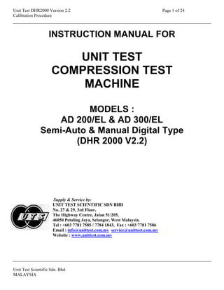
  • 1. Unit Test DHR2000 Version 2.2 Page 1 of 24 Calibration Procedure Unit Test Scientific Sdn. Bhd. MALAYSIA INSTRUCTION MANUAL FOR UNIT TEST COMPRESSION TEST MACHINE MODELS : AD 200/EL & AD 300/EL Semi-Auto & Manual Digital Type (DHR 2000 V2.2) Supply & Service by: UNIT TEST SCIENTIFIC SDN BHD No. 27 & 29, 3rd Floor, The Highway Centre, Jalan 51/205, 46050 Petaling Jaya, Selangor, West Malaysia. Tel : +603 7781 7585 / 7784 1843, Fax : +603 7781 7586 Email : info@unittest.com.my service@unittest.com.my Website : www.unittest.com.my
  • 2. Unit Test DHR2000 Version 2.2 Page 2 of 24 Calibration Procedure Unit Test Scientific Sdn. Bhd. MALAYSIA Thank you for purchasing UNIT TEST compression test machine, quality Malaysian made product from UNIT TEST SCIENTIFIC SDN. BHD. Being one of the pioneers & experienced testing equipment manufacturers, UNIT TEST compression test machines have been exported worldwide for more than a decade ago. The presence of UNIT TEST compression test machines can be felt throughout the world especially at the booming modern construction projects, universities, testing laboratories, construction material factories, R & D centre’s, colleges etc. The reliability, consistency & accuracy of the test results produced using UNIT TEST compression test machine providing peace of mind to users. For proper use of this machine, please read this manual carefully in order to ensure safe & correct operation. Make sure only well trained & qualified personnel are allowed to operate this machine. Please refer to the relevant test standard used for complete guide on making samples, testing method & interpretation of test results. Please fill in your company particular below :- Company : Telephone no. : Email address : Purchase date : Remark : Should you need parts replacement for this machine in the future or you need to purchase additional items, please contact our office or your local agent. Thank you for your continuous support.
  • 3. Unit Test DHR2000 Version 2.2 Page 3 of 24 Calibration Procedure Unit Test Scientific Sdn. Bhd. MALAYSIA CONTENTS 1 Introduction 4 2 Operating procedure 4 3 Advanced Options 5 3.1 Raw Data Setup 5 3.2 Data base Initialization 6 4 Equipment 7 4.1 Clear Logs 8 4.2 Print Option 8 5 Setting sample type 9 6 Setting the Base, Rate & %Fail 10 7 Transferring the test result from DHR 2000 to computer 11 8 Retrieve test result & print 12 9 Test precautions 13 10 Calibration and Setup 14 10.1 Transducer Calibration 14 10.1.1 Zero and Span Adjustment 14 10.1.1.1 Linearisation Adjustment 15 11 Calibration procedure 16 12 DHR 2000 display features 20 13 DHR 2000 keypad features 22 14 Specifications 23 15 Maintenance 23 16 Control panel diagram 24
  • 4. Unit Test DHR2000 Version 2.2 Page 4 of 24 Calibration Procedure Unit Test Scientific Sdn. Bhd. MALAYSIA 1. INTRODUCTION In construction industry, concrete plays a major role by becoming the main item to be used either in building or highway projects. Concrete is a mixture of few materials such as cement, sand, aggregate, water, chemical etc. The ratio of these materials being used will determine the strength of concrete to be produced. The quality of concrete can be directly affected by its content mixed together. Therefore the quality of concrete must be measurable in order to know the strength it can withstand for its relevant application. The ratio of the materials used can then be controlled efficiently using UNIT TEST compression test machines. 2. OPERATING PROCEDURE All procedures mentioned for semi-auto machine, except procedure for manual machine only in bracket ( ) 1. Place a concrete sample onto the center of lower platen. NOTE: Samples must be positioned exactly on the center of lower platen, using the guides provided on the platen. If the guides cannot support a particular sample, draw lines on the platen so that the sample can be put at the center of the platen. Samples not positioned center enough may damage the upper ball seating attached to the upper platen. NOTE: Make sure the gap between the sample top surface & upper platen is not more than 15mm, as to avoid the machine piston from over traveled. 2. Close the safety fence. 3. Switch on the display & power pack by pressing the on/off switches. 4. Rotate the load release valve clockwise to stop the oil from flowing back to the tank. NOTE: The load release valve must not be over-tightened, or its thread may damage. That’s why it’s advisable to rotate it using only 1 finger until it’s just tight. 5. At the keypad, press MAN, ENTER TARE. NOTE: If Weight & Reference need to be changed, after pressing MAN then move the arrow to Weight & Reference to change its value. Press ENTER after changed. Then continue with ENTER & TARE. 6. Press the rapid approach switch continuously to raise up the sample to upper platen faster. When the sample has just touches the upper platen, let go the rapid approach switch. 7. Rotate the speed controller clockwise (push the speed controller forward for manual machine) until the Base value is achieved. 8. With reference to the +5% & -5% speed indicator bar, control the speed so that it is as near as possible to the center of the bar. 9. When the sample is about to crushed, the motor will tend to slow down due to lots of strength at the sample (ending stage). Increase the speed to the +5% side as far as possible. 10. Once the display shows “Now Printing, Please Wait”, rotate the load release valve anti-clockwise one round to release the oil back to the tank. 11. Remove the crushed sample & clean the machine with brush or cloth. 12. Repeat the complete procedure to start a new test.
  • 5. Unit Test DHR2000 Version 2.2 Page 5 of 24 Calibration Procedure Unit Test Scientific Sdn. Bhd. MALAYSIA ***ATTENTION LABORATORY SUPERVISOR*** These are the passcodes for ENG and SETUP. You may wish to remove this page and keep in a safe place separate from the Instruction Manual to avoid unauthorized adjustment of the calibration data. Entry code for ENG key : 4298 3. ADVANCED OPTIONS This chapter shows you how to tune your DHR2000 instrument in order to operate effectively. From the Main Screen (CHAPTER 2) press the ENG key to access these options. You will need to enter a valid Pass code in order to be allowed. This pass code is given when the instrument is delivered and should be stored in a safe place. 3.1 Raw Data Setup Select each of the transducer to be programmed choosing the NEXT option as appropriate. The display will show the current input reading (in Raw Divisions) so that any changes you make can instantly be observed. i. Filter this is a value that determines how many readings are taken to average out noisy line. A value of 30 is recommended for most cases, but you can determine the best setting by applying some load and changing the filter value. Observe when the raw reading stops changing rapidly. ii. Amplifier This is the gain to be applied to the signal received from the transducer. To set it, select a value 01, 02, 04, 08, 16, 32 or 64 (other values are accepted but internally they are always rounded off to one of the values indicated above). Apply Full-Scale load and observe that the raw reading covers the expected range. You may need to increase or decrease the Gain setting as appropriate. The programmed values are also included in the Channel Calibration printouts described on CHAPTER 10.
  • 6. Unit Test DHR2000 Version 2.2 Page 6 of 24 Calibration Procedure Unit Test Scientific Sdn. Bhd. MALAYSIA 3.2 Data base Initialization By choosing this option, you can reset your instrument to factory default values. It is divided into initialization of metric (Init Metric) or imperial (Init Imperial). If you choose Init Metric, the following happens: - i. All memory logs are erased. ii. Equipment Setup:- Type: Compression Units: Metric Peak Hold? Yes Query Abort? Yes Show Proceed: No Sensitivity: 10 SwitchOver: 002050 (kN) Over load: 002020 (kN) *Custom Details *Back iii. New Test Setup:- Stage: 01/02 Index: AAAAAA Reference: 000001 %Fail: 20 Type: Compression Base: 0010.0 (kN) Rate: 0006.0 kN/s Target: 0000.0 (kN) *Taring Conditions* *Clear TARE* *Sample* *Back* iv. Transducer Input defaults. These fields are not altered. This means that your Calibration and Linearisation data is preserved. The only way to change this is by recalibrating again.
  • 7. Unit Test DHR2000 Version 2.2 Page 7 of 24 Calibration Procedure Unit Test Scientific Sdn. Bhd. MALAYSIA 4. EQUIPMENT There are a number of features, which can be configured to suit your installation or preferences. This option can be selected via SETUP key followed by option 3. i. Units? Select Metric or Imperial. The units used will change between kN and Lbf, mm and in, MPa and PSI. ii. Peak Hold? Select YES to freeze the display of the maximum load detected during a test, or NO if this is not required. Note that this option affects only the display on the Main Screen. iii. Query Abort? Select YES to make sure that a warning is given whenever a test is aborted (pressing the ABORT key) manually. This can help to prevent ending a test inadvertently. Otherwise, select NO. iv. Sensitivity? Enter the percentage error measured while a test is running that will fill the error box shown on the Main Screen (CHAPTER 2). Usually the %Error Band is 05, but note that entering a value of 00 will effectively prevent the box from being shown. v. SwitchOver: Enter the loading level at which the instrument will automatically switch from the Range to the HIGH transducer ranges. This is applicable to Compression Tests only. vi. Over load: To prevent the frame being damaged by applying a large loading, you can define a level above which the instrument giving a long bleep, indication that the machine is overloaded. You have to switch off the power switch immediately. vii. *CUSTOMISE* You can define text to appear as Headers and Footers in all printouts available (Test Results and Transducer Calibration). Enter for example a description or your Company’s name, Customer details, etc. viii. *TARE* You define here the parameters to be used during the Taring Stage of a test execution – see CHAPTER 3. Maximum This is the maximum loading that will be allowed to be tared. If the level is exceeded when a test is tared, the test will be aborted.
  • 8. Unit Test DHR2000 Version 2.2 Page 8 of 24 Calibration Procedure Unit Test Scientific Sdn. Bhd. MALAYSIA 4.1 Clear Logs This will erase the non-volatile memory, removing the results of any previous tests carried out by your DHR2000 instrument. A warning will be presented first, to avoid erasing data inadvertently. You can choose to proceed or to cancel the request. 4.2 Print Option 1. Data and Summary 2. Data Only 3. Summary Only 4. Back
  • 9. Unit Test DHR2000 Version 2.2 Page 9 of 24 Calibration Procedure Unit Test Scientific Sdn. Bhd. MALAYSIA 5. SETTING SAMPLE TYPE To access to sample type selection, press the DP TEST key. Press the up/down keys () to select for SAMPLE & press ENTER. Display will show the following samples selection :- 1. Standard cylinder 2. Standard Cube 3. Non Stdrd Cylinder 4. Non Stdrd Cube 5. Beam Block 6. Special Area 1. Standard Cylinder : Press key no. 1. For example if the sample to be tested is a 150mm  x 300mm height standard , move the arrow to Diam. & press ENTER. Press the up/down keys to select 0150 & press ENTER. Move the arrow to Length & press ENTER. Press the required Length of 0300 & press ENTER. Then press ABORT to exit. 2. Standard cube : Press key no. 2. For example if the sample to be tested is a 150mm standard cube, move the arrow to Cube & press ENTER. Press the up/down keys to select 0150 & press ENTER. Then press ABORT to exit. 3. Non Stdrd Cylinder : Press key no. 3. For example if the sample to be tested is a 151mm  x 303mm height non-standard cylinder, move the arrow to Diam. & press ENTER. Press the required diameter of 0151 & press ENTER. Move the arrow to Length & press ENTER. Press the required length of 0303 & press ENTER. Then press ABORT to exit. 4. Non Stdrd Cube : Press key no. 4. For example a cube sample may have measured dimensions of non-standard width 151mm, length 152mm & depth 153mm. Move the arrow to Width, Length & Depth & key in the required dimensions accordingly. Then press ABORT to exit. Please refer to the following cube diagram of the actual position to be put into the machine : Width Depth Length 5. Beam Block : Press key no. 5. For example the beam sample may have dimensions as in the diagram below :-
  • 10. Unit Test DHR2000 Version 2.2 Page 10 of 24 Calibration Procedure Unit Test Scientific Sdn. Bhd. MALAYSIA 500mm 100mm 100mm Move the arrow key to Width & press ENTER. Press the required width of 0100 & press ENTER. Move the arrow to Length & press ENTER. press 0300 & press ENTER. The Length is the distance between the bottom rollers of flexural machine of 300mm apart for this beam size, not the length of the beam sample. (for 150 x 150 x 750mm beam, the bottom roller distance is 450mm) Move the arrow to Depth & press ENTER. Key in the required 0100 & press ENTER. Then press ABORT to exit. NOTE : Do not enter the sample Weight at this part. The Weight can be entered easily during the Manual operation. Please refer to the Manual operating procedure. 6. SETTING THE BASE, RATE & % FAIL The Base, Rate & % Fail features can be accessed by pressing the DP TEST key & if necessary to change, make sure the correct Sample is selected first. For example to set the Rate at 6.8kN/s, press the DP TEST key & move the arrow to Rate & press ENTER. Press 0068 & press ENTER to confirm. Follow the same procedure to set for Base & % Fail if required. Refer to DHR 2000 display features (CHAPTER 12) for further explanation on these 3 features.
  • 11. Unit Test DHR2000 Version 2.2 Page 11 of 24 Calibration Procedure Unit Test Scientific Sdn. Bhd. MALAYSIA 7. TRANSFERING THE TEST RESULT FROM DHR 2000 TO COMPUTER 1. Use an optional RS232 serial cable of 25 pin male (to display) & 9 pin female (to computer) commonly known as modem cable. 2. Follow the below setting in computer prior to transfer data from DHR 2000 display : 3. Start Accessories Create shortcut on desktop to skip these steps Communications Hyperterminal Enter file name & click OK Enter Com 1 or Com 2 & click OK Bits per second : 9600 Data bits : 8 Parity : None Stop bits : 1 Flow control : Xon/Xoff Click Apply & OK 4. Transfer options : a) Transfer automatically test detail after each test -computer is set & connected to computer during testing or b) Transfer later after testing -select test detail by pressing key no.2 or test summary by pressing key no.3. Then press ENTER to select Print option to transfer the test results to PC. Press up/down keys to select test detail page to transfer. 5. 'Save As' to any desired folder & location after transferring. 6. To open in Microsoft Excel for graphical representation or analysis, double click on Excel icon, select Open, Files of type : All Files & select the saved hyperterminal file. The data in Excel format may look a little messy, so some amendment is necessary. NOTE : Depending on the size of data stored, the DHR 2000 memory will become full. If this happen then press key no. 7, press passcode 4298, press ENTER, press key no. 3 to select Clear Logs & press ENTER to clear all test result in the memory. NOTE : Passcode shall be kept confidential by superior or manager in charge, to avoid unauthorised changes. NOTE : If unable to transfer, switch the position of the orange & grey wire at the DHR electronic board connector.
  • 12. Unit Test DHR2000 Version 2.2 Page 12 of 24 Calibration Procedure Unit Test Scientific Sdn. Bhd. MALAYSIA 8. RETRIEVE TEST RESULT & PRINT The DHR 2000 display is also able to connect to certain printers by using an optional RS232 serial cable of both sides 25 pin male. Some examples of A4 paper printers that can be connected such as Panasonic KX-P1131 & Epson LQ-300+. Please note that the Epson printer needs to be set to correct baud rate of 9600, 8 data bits & None parity before it can be used. Another commonly used is the Star SP700 mini printer which uses 76mm paper rolls. The only setting for this printer is to off the dip switch no.4 located at the bottom of the printer (remove the steel cover using a '+' screwdriver & total of 10 dip switches can be seen) To print during testing, simply connect & on the printer. It will print the test detail immediately after sample crushed. To print the test detail or summary anytime after test, follow the simple procedure as below :- NOTE : The 2 A4 printers mentioned above have been used by our customers. There may be other compatible printers in the market can be tried, as long as the printers have serial port. But printers with both serial & parallel ports are slowly obsolete in the market due to its low demand. Another alternative will be the 76mm paper roll mini printer as mentioned above. A) PRINTING TEST DETAIL (1 TEST PER PAGE) 1. Press key no. 2. 2. Press the up/down keys to select for the desired page. 3. Press ENTER. 4. Press key no. 1 to select PRINT. Now the printer will start printing the test detail. 5. Press ABORT twice to exit from the test detail after finish printing. B) PRINTING TEST SUMMARY (10 TEST PER PAGE) 1. Press key no. 3. 2. Press the up/down keys () to select for the desired page. 3. Press ENTER. 4. Press key no. 1 to print all tests. 5. Press ABORT twice to exit from the test summary after finish printing.
  • 13. Unit Test DHR2000 Version 2.2 Page 13 of 24 Calibration Procedure Unit Test Scientific Sdn. Bhd. MALAYSIA 9. TEST PRECAUTIONS 1. Before testing of concrete samples, make sure the following settings are correct according to the requirement of the relevant samples to be tested : Compression mode, Base, Rate, %Fail, sample type (Standard Cylinder or Standard Cube) & Dimensions (Width, Depth & Length). 2. The best clearance between the sample & upper platen should be about 10mm. It should not exceed 25mm. Clearance that is bigger than 25mm will cause the piston to be over travel which may damage the piston & cylinder. To solve this problem, use the suitable thickness of distance piece or you may order from Unit Test Scientific or your local agent. 3. For testing of concrete cylinders, make sure both ends of the cylinder are being capped evenly as required by the standard. Cylinders that are not capped have uneven surface that may damage the machine alignment. 4. For testing of concrete cubes, make sure the uneven surface is facing out (facing the machine operator) & only very flat surface touches both upper & lower platens. 5. Always keep the machine in clean condition after use. 6. Not suitable to test block samples, as it may damage the component part of top platen & causing machine alignment problem. (Please enquire for block testing machine) 7. Should the voltage supplied to the machine is fluctuating (not stable), use a voltage regulator or stabilizer connecting to the machine. Unstable voltage will damage the machine digital part. 8. Always position the sample on the center of lower platen using the guides or lines provided. Sample that is out of the center can damage to machine alignment. 9. Not suitable for testing of smaller samples such as 50mm mortar cube or 40x40x160mm mortar prism. A smaller capacity & more precise machine shall be used. 10.DURING EMERGENCY, SWITCH OFF THE MACHINE IMMEDIATELY & RELEASE THE MANUAL LOAD RELEASE VALVE.
  • 14. Unit Test DHR2000 Version 2.2 Page 14 of 24 Calibration Procedure Unit Test Scientific Sdn. Bhd. MALAYSIA 10. CALIBRATION AND SETUP This chapter shows you how to operate DHR2000 instrument in order to set it up to run efficiently. From the Main Screen (CHAPTER 10), press the SETUP key to access these options. You will need to enter a valid Passcode in order to be allowed. This passcode is given when the instrument is delivered and should be stored in a safe place. 10.1 Transducer Calibration *** IMPORTANT *** During calibration operation, you can control the applied load by operating the external Speed Control Pot. Note also that your DHR2000 instrument processes the electronic signals received from the transducers according to the Filtering and Amplification parameters defined in CHAPTER 5. 10.1.1 Zero and Span Adjustments i. First of all select the transducer Range or FLEXURAL range by positioning the cursor next to the channel identification line and then pressing the ENTER key until the required one is shown. ii. Next select the Scale field and enter the required load value at Full Scale, normally 2000 (HIGH) sometimes maybe 1500, 3000, 4000 or 5000 and depends on machine capacity and 100 (FLEXURAL) kN respectively. iii. Select and activate the *CLEAR* option to start a new calibration. You will be warned about the implications of clearing calibration data previously stored. You can then choose to proceed or not. iv. Make sure that the oil valve is closed, the fast pump is off and no load is currently being applied with Speed Control Pot is set to give a steady oil flow rate. When the readings are stable, and the platen is off the seating position, select the *ZERO* option. The transducer reading should now show 0000.0, and the field labeled Zero will display the offset measured at this time. v. Now start the fast pump to close the day light and then switch off the fast pump. Slowly apply the load until the Full Scale level has been reached. Maintain the load using the Speed Control Pot so that the readings are stable, and then select the *GAIN* option. The transducer should now show the same value as that configured on the Scale entry (step ii above), and the field labeled Gain will display the raw transducer divisions at this point.
  • 15. Unit Test DHR2000 Version 2.2 Page 15 of 24 Calibration Procedure Unit Test Scientific Sdn. Bhd. MALAYSIA vi. Open the oil valve to release the loading. The first stage of a transducer calibration is now complete. vii. Repeat the above procedure from iii to vi for Range and FLEXURAL range where applicable. 10.1.1.1 Linearisation Adjustments The DHR2000 instrument allow you define an interpolation table of up to 20 points for each channel to correct small variations in transducer linearity throughout the complete measuring range. Each table entry consists of an Expected reading and the corresponding measured value. You move between entries by using the arrow keys. Select a field for editing by pressing the ENTER key. Note that not all entries need to be used. i. Apply the load manually until the Expected loading is achieved. ii. Enter the Measured field. You can either:-  Make a note of the transducer reading displayed at the bottom of the screen and copy it into the Measured Column, or  Press the TEST key to let DHR2000 do this automatically for you. Note that this wills only works if the transducer reading is within +/- 5% of the expected value, otherwise the instrument reject the option. iv. Continue with all table entries as above. Press the ABORT key to end the adjustments and return to the previous screen.
  • 16. Unit Test DHR2000 Version 2.2 Page 16 of 24 Calibration Procedure Unit Test Scientific Sdn. Bhd. MALAYSIA 11. CALIBRATION PROCEDURE All UNIT TEST compression testing machines have been calibrated in the factory using our load cells. However once it arrives in your country, the machine may experience slight inaccuracy due to transportation, different load cell used & environment. You should have your machine calibrated by your local authority once the machine has been put at your permanent place. Make sure the machine is placed onto a flat & level cement or concrete surface to prevent from unstable force distribution during crushing that may contribute to doubts. UNIT TEST compression testing machines can be calibrated easily & adjustment to desired accuracy can be fine-tuned easily through its user friendly calibration function, even after long term of usage. Please read & follow the simple procedures before attempting to perform calibration on this machine Very importantly, calibration devices (load cell or load column) used must be positioned as center as possible on the machine lower platen. Use a ruler or caliper to position the device on the lower platen so that all distance a, b, c & d are the same :- Load cell that is not positioned on the center of lower platen may damage the machine alignment & can cause inconsistent readings. A) CHECKING THE INITIAL ACCURACY 1. Place the load cell (or proving ring, load column or other suitable capacity of force measuring devices) on the center of lower platen. 2. Make sure the clearance between load cell & upper platen is not more than 25mm. If the clearance is too much, add suitable thickness of distance piece to reduce to the smallest possible clearance. If still unable to reduce, place flat hardened steel onto the load cell. NOTE : Clearance more than 25mm will probably cause the machine piston to be over-traveling & may damage the piston & cylinder. The ideal clearance between the load cell & upper platen will be about 10mm 3. Switch on the machine & press MAN, ENTER, TARE. Close the machine load release valve. 4. Press the rapid approach switch & watch the load cell moving up fast to the upper platen.
  • 17. Unit Test DHR2000 Version 2.2 Page 17 of 24 Calibration Procedure Unit Test Scientific Sdn. Bhd. MALAYSIA 5. When the load cell almost touches the upper platen, release the rapid approach switch. 6. Operate the manual speed controller until the desired 1st reading of calibration force shown at load cell (e.g. 400kN) & immediately decrease the machine speed to hold the pressure. NOTE : BS EN 12390-4:2000 requires calibration starting at 20% of the machine capacity then upwards of at least 5 equip-spaced forces. Example for 2000kN machine, forces to be calibrated are 400kN, 800kN,1200kN, 1600kN, 2000kN. But if testing condition requires calibrating below 400kN, then additional small capacity device shall be used (e.g. 500kN load cell) to calibrate 100kN, 200kN & 300kN. NOTE : When the load cell almost reaches the desired force, slow down the speed controller so that the reading can be hold easily. 7. Record the reading shown on the machine display (e.g. maybe 404kN) 8. Repeat the control of manual speed controller to apply force onto the load cell, until the load cell shows the second required calibration value (e.g. 800kN) & record the value immediately shown on machine display (e.g. maybe 811kN) 9. Repeat the whole applying force to load cell & recording the machine reading for the rest of the calibration forces. 10. Below is an example of machine’s initial accuracy : Applied force at load cell (kN) Machine reading (kN) % Error 400 410 2.50 800 809 1.13 1200 1177 -1.92 1600 1633 2.06 2000 1965 -1.75 NOTE : % Error = Machine reading – Applied Force x 100 Applied force B) ENTERING THE LOAD CELL VALUE TO RANGE SCALE Depending on reference test standard, certain % error that is out of tolerance is not acceptable (e.g. the error for 400kN is 2.50% which is out of ± 1.0% error requirement for Class 1 machine).If adjustment is necessary, it’s better to clear all the factory calibrated values by following the below procedure. NOTE : But if all the % errors are acceptable, no adjustment is needed. NOTE : It is recommended to perform the procedure in this PART B if the errors recorded are about 3% & above because it is difficult to correct the error for each force as mentioned in PART D. Otherwise if the errors are 3% & below, skip PART B & C to proceed to PART D to adjust minor errors in the Linearisation section which has already been entered in factory. 1. Press key no. 7. 2. Press passcode 4298. 3. Press key no. 1 to select Calibration. Now the screen is at Range I/P. 4. Press the up/down key ( ) to move the arrow () to Clear Scale & press ENTER. 5. Press ENTER again to confirm clearing all calibration data. 6. Re-enter the Scale as 2000 kN. 7. Move the arrow to Set Zero & press ENTER.
  • 18. Unit Test DHR2000 Version 2.2 Page 18 of 24 Calibration Procedure Unit Test Scientific Sdn. Bhd. MALAYSIA 8. Press ENTER again to confirm clearing the initial load value. 9. Move the arrow to Set Gain. (DON’T PRESS ENTER YET) 10. Close the machine load release valve. 11. Operate the machine until the load cell showing 2000kN & immediately hold the pressure. 12. Press ENTER (the arrow already at Set Gain) 13. Press ENTER again to confirm entering the 2000kN scale to transducer. 14. Open the load release valve. NOTE : At Range, Scale must be 2000Kn, Scale is machine capacity. (E.g. if machine is 2000kN capacity, then Scale is 2000kN & if machine is 3000kN capacity, then Scale is 3000kN) If the Scale at ranges is not correct, then key in the right scale accordingly. 15. Press ABORT to exit to setup menu & press ABORT again to exit to main screen. C) CHECKING THE ACCURACY AFTER ENTERED THE LOAD CELL VALUE & LINEARISE (MINIMISE) THE ERRORS Repeat the whole procedure as in PART A to check the accuracy again for the desired forces. The result may look like the following example : Applied force at load cell (kN) Machine reading (kN) % Error 400 404 1.00 800 809 1.13 1200 1211 0.92 1600 1618 1.13 2000 1978 -1.10 As shown in the result, there may be slight error even after enter the load cell value which is normal. If you are satisfied with the results, no adjustment is needed.If adjustment is necessary reduce the forces to less than ±1.0%, please proceed to the following procedure: 1. At main screen, press key no. 7. 2. Press passcode 4298. 3. Press key no. 1 to select Calibration. 4. Move arrow to Range. 5. Move arrow to Linearisation & press ENTER. 6. Key in all the calibration results as illustrated in the example above as follows :-
  • 19. Unit Test DHR2000 Version 2.2 Page 19 of 24 Calibration Procedure Unit Test Scientific Sdn. Bhd. MALAYSIA No. Expected Measured 01 000400 000404 02 000800 000809 03 001200 001211 04 001600 001618 05 002000 001978 06 000000 000000 07 000000 000000 08 000000 000000 09 000000 000000 10 000000 000000 7. After key in all the forces above, press ABORT to exit to setup menu & press ABORT again to exit to main screen. D) CHECKING THE ACCURACY AFTER LINEARISATION & CORRECTING MINOR ERRORS Repeat the whole procedure as in PART A to check the accuracy again for the desired forces. The LINEARISED result may look like the following example : Applied force at load cell (kN) Machine reading (kN) % Error 400 401 0.25 800 799 -0.25 1200 1205 0.42 1600 1617 1.06 2000 1977 -1.15 Although Linearisation has been done, it sometimes may or may not adjusting the machine reading to be the same as the applied force perfectly. As shown in example above, the errors at 1600kN & 2000kN already exceeded ±1.0%. Again if the results are satisfying, no adjustment is necessary. But if it’s a requirement for errors to be ±1.0% or less, then a minor adjustment should be done as follows:- 1. Enter into the Linearisation page in Range by following the procedure as in PART C (step 1 to step 5) 2. Press the up/down key ( ) to move the arrow () to “1618”kN at the “Measured” section. 3. Since there is an error of 17kN (machine reading 1617kN – applied force 1600kN), you need to add this 17kN error to the force “1618”kN at the “Measured” section. Press ENTER & change the reading to 1635kN. Press ENTER again. 4. Press the up/down key ( ) to move the arrow () to “1978”kN at the “Measured” section. 5. Since there is an error of -23kN (machine reading 1977kN-applied force 2000kN), you need to deduct this 23kN error from the force “1978”kN at the “Measured” section. Press ENTER & change the reading to 1955kN. Press ENTER again. 6. Press ABORT twice to exit to the main screen. 7. Now repeat the whole procedure as in PART A to take another series of force readings. Now all the errors should be minimized to within ±1.0%.
  • 20. Unit Test DHR2000 Version 2.2 Page 20 of 24 Calibration Procedure Unit Test Scientific Sdn. Bhd. MALAYSIA 11. DHR 2000 DISPLAY FEATURES 1. Force value : Displaying the current force value in kN. It will increase accordingly when pressure is applied to the machine piston. 2. Speed indicator bar : Indicates the current loading speed according to the set Rate. To be controlled by user manually. 3. Status : Loading status of the machine, either Ready (not operating), Started (operating), or Finish (Sample crushed, machine has stopped) 4. Peak : Is the maximum force achieved after the sample has crushed. 5. Date & Time : Showing the current date & time. Only need to set once. 6. Reference : Showing the test number. It will increase in sequence by itself if not set. 7. Base : When set at 10kN, the speed indicator bar will start to show only when the load reaches 10kN in order to eliminate initial unstable speed caused by deadweight. (Factory default & recommended Base is 10kN. The minimum sample failure value should not be less than the Base value. For example if the sample crushed at 8.6kN, then the Base must be set at 5kN. The Rate set must be less than the Base value. For example if the rate is set at 12kN/s, then the Base must be set at 15kN or 20kN)) 8. Rate : User preset loading speed in kN/s. Must be set according to sample's test standard. 9. % Fail : Preset percentage of damage at the concrete sample in order for the machine to inform the user to stop the operation. (see Note below)
  • 21. Unit Test DHR2000 Version 2.2 Page 21 of 24 Calibration Procedure Unit Test Scientific Sdn. Bhd. MALAYSIA 10.Tare : Temporary storage for the initial tared (zeroed) force value upon starting of operation. Not adjustable. 11.Standard cube : Preset sample type (standard or non-standard cube, standard or non-standard cylinder, beam block & special area) 12.Dimensions : Description of sample dimension (width, depth & length) 13.Sample size : Measurement of sample dimensions in mm. 14.Area : Area of sample surface that is in contact with upper platen. 15.Stress : Auto calculation of concrete strength in Mpa obtained from the peak value & Area. NOTE : The following diagram is an example of preset % Fail 10% 20% 40% Factory preset for % Fail is 15% to 20%. But if the sample damages too much or explodes before the machine informs to stop, reduce the % Fail. But the % Fail should not be set too low causing the machine to inform even before the sample reaches its maximum strength. There is no standard guideline for % Fail & if it’s necessary to reduce it, trial & error for the same samples few times as illustrated at the graph below :- Strength (Mpa) Maximum strength achieved even before the machine inform the user to stop % Fail The minimum % Fail must be determined so that the machine will stop only after maximum strength is achieved. It may vary for different sample types.
  • 22. Unit Test DHR2000 Version 2.2 Page 22 of 24 Calibration Procedure Unit Test Scientific Sdn. Bhd. MALAYSIA 13. DHR 2000 KEYPAD FEATURES Key features : 1. DP, TEST - Change Compression / Flexural mode, Base, Rate, % Fail & Sample type. 2. 0 (TARE) - To tare off (zero) any initial value during beginning of test. 3. HELP - Simple explanation on Channel Calibration (refer to instruction manual for detail explanation) 4. 1 (CLOCK) - Adjust the Time & Date 5. 2 (PRINT) - Show 1 test result in detail per page. Press the  keys to view the previous result. Press ENTER & select PRINT to print or transfer the result to computer. 6. 3 (SUM) - Show 10 test results in summary per page. Press the  keys to view the previous 10 results. Press ENTER & either select PRINT (to print / transfer the current page only) or PRINT ALL (to print transfer the first until the last result) 7. 4 (SCR) - Press to zoom the display bigger. Press again to return to original size. 8. 5 – No function 9. 6 (SOL) – No function 10. 7 (SETUP) - Calibration setup (confidential password required), overload trigger & clear memory. (FOR CALIBRATION USE ONLY) 11. 8 – No function 12. 9 (ENG) - Raw data to amplify the transducer value & PID control for automatic setup of motor speed & parameter. (FOR FACTORY & CALIBRATION USE ONLY) 13.  - For moving the arrow cursor up or down 14. MAN () - For machine operation in Manual mode. Press MAN (change the Reference, Weight etc. if required), ABORT & TARE (TARE must be pressed for all manual modes) Also for moving the arrow cursor up or down.
  • 23. Unit Test DHR2000 Version 2.2 Page 23 of 24 Calibration Procedure Unit Test Scientific Sdn. Bhd. MALAYSIA 15. ENTER - Press ENTER to change a data & ENTER again to fix the data after changing. 16. ABORT - Exit from a setting or page in the screen. Also use to cancel the machine operation at any time during testing. 14. SPECIFICATIONS 1. 2 channel programme (Compression mode 0.1 kN resolution & Flexural mode 0.01 kN resolution) connectable to 2 machine frames with 1 controller. 2. Storage of test results in memory & transferring of data to computer or printer. 3. Large 75 x 125mm clear LCD display c/w zoom function. 4. User input of loading Rate for manual controls of testing speed. 5. Sample type, size & weight selectable for auto calculation of Mpa & Density. 6. User friendly operation with simple & clear page by page instruction. 7. Calibration c/w passcode protection & accuracy adjustment system (linearisation) for achieving ±1.0% accuracy over the whole calibrated range. 8. User input of testing limit (overload) in kN for automatic alarm trigger. 9. Machine frame built to be tough, long lasting & providing very consistent test results. Used for testing various sizes & types of standard concrete samples. 10. Power : 240V, 50Hz, 1ph 15. MAINTENANCE 1. There is virtually very minimal maintenance for this machine. However it is very important that the user follow each & every correct operating procedure to ensure this machine is always in perfect working condition. 2. Pay attention to the Precaution section especially on the positioning of samples, testing smaller samples, piston traveling limit, etc. 3. Inspect the top & bottom platen for wear by checking its flatness to observe if they are dented. 4. This machine only use hydraulic oil grade 68, which should be changed ideally once a year. The oil level should be always full. Open the nut of the square oil tank located at bottom of power pack. Insert your finger into the oil tank. If you can touch the oil, it’s full. If you can’t touch, then you need to top up. 5. Occasionally check if the protective rubber cover does not tear off causing oil leakage. Before changing a new rubber cover, replace with new hydraulic oil grade 68. 6. It is a normal National Standard requirement to request for calibration at least once a year, after relocating the machine or repair which is likely to affect the machine accuracy.
  • 24. Unit Test DHR2000 Version 2.2 Page 24 of 24 Calibration Procedure Unit Test Scientific Sdn. Bhd. MALAYSIA 16. CONTROL PANEL DIAGRAM Rapid Approach Switch (2) Power Switch (1) Key Speed Controller (4) Load Release Valve (3) Power Switch (1) Key Speed Control Knob (5) Speed Control Lever (4) Load Release Valve (3) Oil Tank Nut Inlet Outlet Rapid Approach Switch (2)