Mais conteúdo relacionado
Semelhante a elctricidad electronica.pdf (20)
elctricidad electronica.pdf
- 1. Copyright © 1999 Wimborne Publishing Ltd and
Maxfield & Montrose Interactive Inc
EPE Online, November 1999 - www.epemag.com - 1047
Much of electronics is about
building blocks, and once you
have understood what some of
the primary building blocks can
do and why they can do it, these
blocks can be combined in many
different ways to achieve
increasingly more sophisticated
goals.
To assist you in
getting to know about
the various building
blocks, a set of
illustrative computer
programs has been
prepared. We believe
these to be capable of
running on any
comparatively recent
PC-compatible
computer (from
Windows 3.1 upwards),
provided that it is
capable of downloading
the programs from the EPE
Online web site. It should
have a color monitor.
SOFT APPROACH
We stress, though, that it is
not necessary to run our
programs in order to gain benefit
downloaded for free from the
EPE Online Library at
www.epemag.com
To install the software on
your computer, follow the
instructions provided in the
TEACH2K.TXT text file that
accompanies the
programs. This can be
read using DOS EDIT or
through any normal
word-processing
software (including
Windows Notepad and
Notebook).
The Teach-In 2000
programs not only
illustrate particular
electronics concepts
discussed in each
Tutorial part, but also
offer you interactive
involvement, with the
ability to specify your
own component values.
Self-test and experimental
exercises are included, to
really let you get to grips with
understanding this fascinating
technology.
In future parts, the software
will additionally allow you to use
your computer as an item of test
Hi there! What we propose to do during
this 10-part Teach-In 2000 series is to lead you
through the fascinating maze of what
electronics is all about! We shall assume that
you know nothing about the subject, and so
shall take individual components and concepts
in simple steps and show you, with lots of
examples, what you can achieve, and without it
taxing your brain too much!
3$57 2QH ,QWURGXFWLRQ
E -2+1 %(.(5
from following this Teach-In
series. Whilst you will not gain
full benefit without running the
programs, the series is
structured such that it can still
be studied profitably even if you
don’t have access to a PC-
compatible computer.
At present, programs are
available to accompany the first
few parts of this ten part series.
Others are in preparation and
will be available later on in the
series. The software may be
Through these simple steps we hope to prove
to you that using electronic components need
not be a complex task and that, providing you
think about each stage of what you are trying
to create, you can actually design and build
something that works!
In this introductory section, we explain our
approach to the subject, the things you need
to buy, and then lay down a few simple
ground rules.
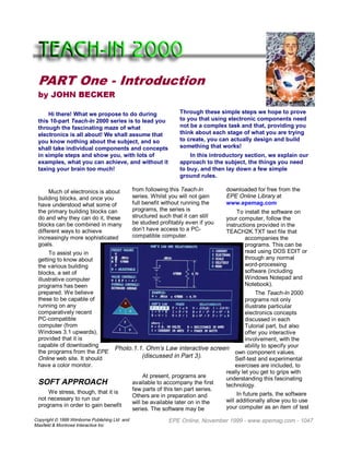
Photo.1.1. Ohm’s Law interactive screen
(discussed in Part 3).
- 2. Copyright © 1999 Wimborne Publishing Ltd and
Maxfield Montrose Interactive Inc
EPE Online, November 1999 - www.epemag.com - 1048
equipment, allowing you to input
data from both analog and
digital circuits, displaying it as
meaningful screen data and/or
waveforms.
This facility will be of great
benefit to you long after you
have learned the information
offered during the series.
COVERAGE
The subjects to be covered
include (amongst other things)
facts and equations for using
resistors, capacitors,
potentiometers, diodes, light
emitting diodes, transistors,
logic gates, other digital circuits,
operational amplifiers, liquid
crystal displays, signal
waveforms, Ohm’s Law and its
derivatives, binary and
hexadecimal logic, analog to
digital conversion, digital to
analog conversion, computer
interfacing, timing calculations,
frequency generation, frequency
counting, and simple audio
amplifying, to name but a few of
the wide array of subjects to be
featured.
The series is not directly
related to any formal courses or
qualifications on electronics, but
is based around those subjects
that the author has found to be
most important during several
decades of involvement in
electronics, both professionally
and as a hobbyist. It should
appeal to anyone of any age
who wants to get to know what
electronics is all about, and to
put it to good use.
JUST PLUG IN
The vast majority of the
Teach-In exercises and
experiments are carried out on
a plug-in breadboard, and use a
6V battery as the power source.
You do not need a soldering
iron for the first several parts of
Teach-In. However, later in the
series, some of the circuits
discussed will benefit from
construction on a printed circuit
board allowing their long-term
use as items of test equipment.
For these constructions a
soldering iron will be needed.
Although this Teach-In will
not instruct you in soldering
techniques, we have available
the excellent and highly-
acclaimed Basic Soldering
Guide by Alan Winstanley,
which will tell you all you need
to know – it also is obtainable
from the EPE Online Library at
www.epemag.com
WHAT YOU NEED
There are two groups of
items you need, comprising
hardware and the electronic
components themselves. You
should get many years of value
out of them!
Some of our suppliers are
putting together special Teach-
In packs and readers should
check out the Shoptalk page.
QUANTITIES
The quantities and values of
components we suggest are not
only sufficient to allow you to
perform the wide variety of
experiments we discuss, but will
also result in a good “spares”
collection for future long-term
use. Go for larger quantities than
those given for resistors and
capacitors if funds permit (say 10
of each, for example). Where no
quantity is stated, only one item is
required.
With regard to resistors and
capacitors, if you can buy a
“bumper bundle” of mixed values
do so, but do ensure that they are
of reasonable size suited to
breadboard use at a minimum of
10 volts (and that they are of
good quality). They should
include the majority of the values
listed (and possibly other values
7($+,1
'
!
!!
!
!#
!$
!%
!
(
)
!
#
$
%
1 2 3 4 5
'
!
!!
!
!#
!$
!%
!
(
)
!
#
$
%
6 7 8 9 :
Fig.1.1. Arrangement and interconnection of the
breadboard strips. Note that the outer strips be-
tween 31 and 34 are not connected.
Fig.1.2. Example of trimming
and shaping resistor wires to fit
into the breadboard.
- 3. Copyright © 1999 Wimborne Publishing Ltd and
Maxfield Montrose Interactive Inc
EPE Online, November 1999 - www.epemag.com - 1049
as well). Avoid resistors that are
rated for 1 watt or greater since
their size may be too great.
Whilst you may not
understand the values listed
(although you will soon do so!),
your component supplier will if
you just present the list to him.
BREADBOARD
CONSTRUCTION
You will see that the holes
in the breadboard are arranged
in groups of five. Beneath the
holes are miniature electrical
clips. All five clips in a group
are electrically connected and
all groups are electrically
isolated from each other (with
the exception of the two parallel
strips to either side of the
board). The arrangement is
shown schematically in Fig.1.1.
Components are plugged
into and between the clip groups
so that they become inter-
connected in a specific
electrical configuration, as
required so that they perform a
particular function when
electrical power is applied.
Examples are shown in Photo
1.2.
Components are usually
supplied with connecting wires
that are far longer than required
(especially resistors and
capacitors). Prior to plugging a
component into the breadboard,
we suggest that you cut the
wires to a length of about 1¬
¬5
centimeters away from the
component’s body.
This should allow you to
easily handle the components,
yet avoid the possibility of extra
long wires adversely touching
the leads of other components.
The length should also allow
test leads to be clipped onto the
component wires.
You will need to bend the
leads of some components
(resistors and diodes in
particular) so that they plug into
the board. This is illustrated in
Fig.1.2. Make the bend just
fractionally away from the body
of the component, especially
the diodes, which often have a
glass body that may fracture if
subjected to stress when leads
7($+,1
WHAT YOU NEED – Basic Items
o) Digital multimeter, preferably a good one, but even a cheap one
will allow you to perform all the tests we ask you to do during
the series. It is recommended that if you can, you should buy
one which not only has test probes, but also test leads with clips
on one end, allowing the leads to be clipped onto component
wires and legs.
If you cannot obtain clipped leads, you can easily make your
own using two 0¬
¬5 meter lengths of extra-flexible wire, to which
you connect miniature insulated crocodile clips at one end, and
4mm plugs at the other (or to suit meter). The colors should be
red and black.
Battery connection leads can be similarly made, to the same
length, with insulated crocodile clips at each end.
o) Plug-in breadboard, 64 holes long, 14 holes wide, basic hole
spacing (pitch) 0¬
¬1-inch (2¬
¬54mm) – see Photo 1.2.
o) Heavy duty 6V (volts) battery, with spring terminals – see Photo
1.2. Do not use any battery that has a different stated voltage
(e.g. a 9V battery MUST NOT be used).
o) Solid core connecting wire, approximately 22s.w.g. core diame-
ter, one small reel (preferably plastic coated, any color, but may
be “naked”).
o) Wire cutters (for cutting component leads and connecting
wires).
o) Wire stripper for small diameter plastic-insulated wires (typically
size 1¬
¬2mm diameter).
o) Small electrical (insulated) screw driver (blade tip about 3mm
wide).
o) Small thin-nosed pliers, insulated handles.
o) Extra-flexible stranded plastic covered wire (approx. 2mm diam-
eter), 2 meters each of red and black (or green).
o) Miniature crocodile clips, insulated covering, preferably with
screw terminals to which extra-flexible wire can be secured
(they will otherwise need soldering), 10 off (some for future
use).
o) 4mm plugs (optional, see multimeter note above), one each of
red and black, preferably with screw terminals.
o) 1mm terminal pins, double-sided – a handful (see text).
o) 1mm pin headers (say 5 strips, each about 20 pins).
o) Miniature soldering iron, mains powered, 15W, bevel tip approx.
3mm wide.
o) Solder, multi-core, 22s.w.g.
- 4. Copyright © 1999 Wimborne Publishing Ltd and
Maxfield Montrose Interactive Inc
EPE Online, November 1999 - www.epemag.com - 1050
7($+,1
of power/meter leads and their
clips. A better option is to use
the double-sided 1mm terminal
pins listed earlier.
ELECTRICAL
POWER
Two terms that will be used
frequently in this series are
voltage and current. Their units
of measurement are volts and
amps. Sub-units of
measurement are also used,
which will be defined in due
course.
To explain the nature of
electrical power would take us
into atomic physics, which we
have no intention of exploring.
However, we can simply explain
the concepts of the terms by
using a time-honored analogy:
Imagine a water tank with a
hole in its base. We are sure
you know that water will flow out
through the hole at a rate
depending on the fullness of the
tank and the size of the hole.
The greater the pressure of
the water, the faster that it will
flow through the hole. The
pressure depends on the height
of the water above the hole.
The volume of water that flows
through the hole depends on its
diameter. In electrical terms, the
“height” is expressed in “volts”,
the volume of flow is expressed
in “amps”.
There is an allied third term,
watts, which expresses the
amount of power that flows in
respect of given values for volts
and amps (it is the result of the
two values multiplied together).
It is important to be aware
that electronic components will
only accept voltage, current,
and power flow within specified
limits. These limits vary
between component types and
WHAT YOU NEED – Electronic Components
o) Resistors
47W, 100W, 220W, 470W, 1k, 2k2, 4k7, 10k, 22k, 47k, 100k,
220k, 470k, 1M, 2M2, 4M7, 10M (say 5 off each).
All values rated at 0·25W (or 0·33W) 5% carbon film.
o) Capacitors
10p, 22p, 47p, 100p, 220p, 470p (say 5 off each).
All miniature polystyrene or ceramic (disc or plate).
1n, 2n, 4n7, 10n, 22n, 47n, 100n, 220n, 470n (say 5 off each).
All miniature ceramic (disc or plate).
1m, 2m2, 4m7, 10m, 22m, 47m, 100m, 220m, 470m, 1000m,
2200m (say 5 off each up to 100m, 2 off each 220m and
above). All electrolytic, radial mounting.
All capacitors should have a minimum working voltage rating of
10V (a higher voltage rating is acceptable providing the size of
the component is not too great – component suppliers’ cata-
logues should quote the physical size of capacitors in relation to
their capacitance values and voltage ratings).
o) Preset Potentiometers
100W, 470W, 1k, 4k7, 10k, 47k, 100k, 470k, 1M (say 2 off
each). Miniature round, enclosed, horizontal, printed circuit
board mounting.
o) Control Potentiometers
100k linear, 100k logarithmic. Panel mounting, “standard’’ diam-
eter mounting bush and spindle, preferably plastic spindle
(without switch).
o) Semiconductors
Red light emitting diode (l.e.d.), about 5mm diameter (say 10
off)
74HC04 CMOS hex inverter gate (2 off)
74HC14 CMOS hex Schmitt inverter gate (2 off)
o) Miscellaneous
ORP12 (or NORP12) light dependent resistor (l.d.r.)
10k thermistor (n.t.c. type)
are bent. Thin-nosed pliers are
useful to help form the bend.
Components may also be
linked to others using short
lengths of the solid-core wire
specified in the What You Need
sidebar (the cut-off wires of
components can often be used
for the same purpose). Cut the
length you need and then trim
off the insulation (if present) to
a length of about 1cm, using the
wire strippers. Thin-nosed pliers
can shape the wire as required
for plugging in, but you may
simply bend the wire by hand if
you are just making
experimental links.
If you are using uninsulated
solid-core wire, ensure that it
does not adversely contact
other components.
Short lengths of solid-core
wire may also be inserted in the
board to assist in the connection
- 5. Copyright © 1999 Wimborne Publishing Ltd and
Maxfield Montrose Interactive Inc
EPE Online, November 1999 - www.epemag.com - 1051
must not be exceeded (although
there is usually a fairly wide
margin of excess that they will
tolerate for short periods).
All this will become much
clearer as we progress through
the series. Refer now to the first
Tutorial, and let’s start exploring
electronics!
TEACH-IN
2000 –
TUTORIAL 1
COLOR CODES AND
RESISTORS
Rightly or wrongly, we are
going to assume that you don’t
yet know what component types
look like. No doubt we’re wrong
– but we’ve got to start
somewhere!
Once it’s arrived through
your letterbox, within that bag of
components you’ve bought for
this Teach-In series (as
recommended in the What You
Need sidebars) will be some
that look like those in Photo 1.3.
The component on the left
is a light-emitting diode (LED), a
resistor (having four colored
bands) is in the center. The
right-hand component is an
electrolytic capacitor (to be
discussed in Part 2).
LED BY THE LIGHT
Find a red LED, plus a
resistor whose bands are
colored yellow, violet, brown,
and gold, in that order. Plug
them into your breadboard as
shown in Fig.1.3, then clip the
two power leads to your battery
as shown in the Photo 1.4.
You will now see one of two
situations – the LED is glowing
7($+,1
WHAT YOU NEED – Electronic Components cont
A few other components will be called for in later parts of the se-
ries (but not before Part 4). Amongst them will be:
o) 1N4148 signal diode (say 10 off)
o) 1N4001 rectifier diode (say 5 off)
o) BC549 (or 2N3704) npn transistor (say 5 off)
o) BC559 (or 2N3702) pnp transistor (say 5 off)
o) LM358 dual opamp (say 3 off)
o) 74HC00 CMOS quad 2-input NAND gate
o) 74HC02 CMOS quad 2-input NOR gate
o) 74HC08 CMOS quad 2-input AND gate
o) 74HC32 CMOS quad 2-input OR gate
o) 74HC86 CMOS quad 2-input XOR gate
o) 74HC4017 CMOS decade counter
o) 74HC4024 CMOS 7-stage binary ripple counter
o) TLC549 analog-to-digital converter
o) DAC0800 digital-to-analog converter
o) Miniature active buzzer
o) Low-cost pair of high impedance personal headphones
o) Miniature jack socket to suit personal headphones
o) Miniature electret insert microphone
o) 36-way Centronics female parallel printer port connector (PCB
mounting, and for which a PCB will become available)
Photo.1.2. Examining one of the breadboard
experiments in Part 2.
- 6. Copyright © 1999 Wimborne Publishing Ltd and
Maxfield Montrose Interactive Inc
EPE Online, November 1999 - www.epemag.com - 1052
nicely (“turned on”), or it is not
glowing at all! Disconnect the
battery. Now unplug the LED,
turn its leads round the other
way and plug it back in.
Connect the battery again.
Whichever case was true first,
the opposite should be true
now.
This experiment with the
LED is an example of the use of
a semiconductor, a class of
electronic component that has
thousands of members in its
enormous range of families, and
which includes not only such
simple items as LEDs, but also
the highly sophisticated
microprocessor that controls
your computer.
What you have been shown
is that semiconductors will
(normally) only work in a circuit
if they are connected to its
power supply the correct way
round. There are other
components, too, which are
equally dependent for their
correct operation on being
connected the “right” way round.
We shall say more on this as we
progress through the Teach-In
series.
With the LED positioned in
its “glowing” direction, and with
the battery disconnected,
unplug the resistor, turn it round
and plug it back in.
Reconnecting the battery, the
LED should still glow. A simple
second lesson, but just as
important – resistors are
components that are quite
content to be connected either
way round into a circuit.
What we have also implied
through the above examples is
that power supplies should
always be disconnected or
switched off before physical
changes are made to any
circuit. Always do this, even if
we don’t actually say so each
time a change is suggested.
MARKED
DIFFERENCE
Now find a resistor whose
bands are brown, black, red,
and gold, and another whose
bands are red, red, brown, and
gold.
In turn, plug these resistors
into the board in place of the
original one. What do you
observe with each of them? The
LED glows less brightly with the
brown, black, red, and gold
resistor, but glows much more
brightly with the red, red, brown,
and gold one. Now try a brown,
black, yellow, and gold resistor
– no glow at all!
Why the difference in LED
response to components that
look the same physically? Well,
that is the aim of this Teach-In –
to tell you about not just
resistors, but other important
types of components as well, in
such a way that you understand
how they behave and how you
can use them to perform
meaningful tasks in circuits of
your own invention.
The lesson you should learn
from this last experiment is that
components may look alike, but
identifying marks (in this case
colored bands, but they may be
numbers and letters in other
instances) are vitally important
– they state a component’s
“value”.
What that information
conveys depends on the
component type involved, but in
the case of resistors (whose
nature will be explained more
fully later) it states the amount
of “resistance” that they offer to
electrical current when it flows
through them.
Each of the three resistors
7($+,1
Photo.1.3. Left to right: Light-
emitting diode, resistor, elec-
trolytic capacitor.
Photo.1.4. Power leads
clipped to a LED and
resistor experiment.
39@ 21DD5BI F5
514 85B5
39@ 21DD5BI F5
514 85B5
B5C9CD?B
54
D5B=91 @9
Fig.1.3. Component posi-
tions and battery lead con-
nections for the
LED and resistor experiment.
- 7. Copyright © 1999 Wimborne Publishing Ltd and
Maxfield Montrose Interactive Inc
EPE Online, November 1999 - www.epemag.com - 1053
you’ve just used have different
amounts of resistance, and the
color code (once you know how
to read it) tells you that value.
The observed response of the
LED depends on the voltage
applied to it and the amount of
resistance that the voltage has
to flow through. We shall
presently look at resistors in
detail, but first let’s examine
color codes.
BASIC COLOUR
CODES
Whilst resistors are a prime
example of components that are
likely to be color coded, others
such as capacitors, diodes,
inductors, transformers, ribbon
cables, connecting wires, and
plugs and sockets often use
them as well, although perhaps
not quite so widely.
Consequently, one of the
most important skills that any
would-be electronics constructor
should acquire is the ability to
correctly read color codes.
First, then, let’s help you to
become familiar with the basic
color codes and the numbers
that they represent. The way in
which groups of colors are
interpreted on the components
themselves will be described
when we discuss those items.
The 10 basic colors are
allocated as in Table 1.1. As we
shall reveal later, however, they
are not the only colors
available, although the
remainder are not used in the
same way.
We have set up a simple
computer program, which will
help you to learn these color
codes and their values, and to
prove to yourself that you do
actually remember them.
Run the Teach-In software
program and select Menu Basic
Color Codes. In the middle of
the screen you will see the 10
color codes, not only numbered
and named as in Table 1.1, but
also with their colors alongside
them. Do be aware, though, that
the limits of the computer
screen prevent the colors from
appearing in exactly the same
hues as you might see on actual
components.
It has to be
said, however,
that there is no
full
standardization
on the exact
hue that might
be printed on
components by
their
manufacturers
– they seem to
take very wide
artistic license
on occasions.
It’s not
uncommon, for
instance, that it
may be
difficult
sometimes to
differentiate
between one manufacturer’s red,
and another’s orange.
However, what you see on
the screen (your computer being
satisfactorily set-up, of course –
and not driving a black and white
monitor!), should be sufficient to
get you well acquainted with color
codes.
Press S to select Self-Test
On/Off. A “questions” box
appears to the right of the colors
display (Photo 1.5), and the color
order in the main box changes
and the values disappear. Your
task is to use the cursor arrows to
select the color whose number is
given in the question.
A random number generator
variously selects questions on
colors and values. Correct
answers earn you points. So give
yourself a test!
Pressing A provides the
answer if you want it, and S re-
displays the correct color code
sequence and its numbers.
Pressing M returns you to the
main menu.
RESISTORS
With basic color codes under
your belt (or at least on visual
display demand if necessary),
let’s see how they apply to one
particular group of components,
7($+,1
Photo.1.5. Section of the computer program
display that invites you to test your knowledge
of color codes.
Color
Black
Brown
Red
Orange
Yellow
Green
Blue
Violet
Gray
White
0
1
2
3
4
5
6
7
8
9
Coded
Number
Table 1.1. Basic color codes
used in electronics.
- 8. Copyright © 1999 Wimborne Publishing Ltd and
Maxfield Montrose Interactive Inc
EPE Online, November 1999 - www.epemag.com - 1054
resistors.
But, we ask ourselves back
at Editorial HQ, do you who are
reading this actually know what
a resistor is? Perhaps not, even
though you’ve just been using
some, so perhaps we should
explain matters (and apologize
to those of you who do know for
taking up your time – but why
not read it anyway, you might
be reminded of something
you’ve forgotten).
It’s inevitable, of course,
that in explaining resistors we
have to use some terms which
you might not be familiar with
yet. Such terms will be covered
as we progress through the
Teach-In series, and we expect
that eventually you will want to
re-read the series from the
beginning, at which time things
will begin to slot more firmly into
place if they haven’t already.
BLOW THAT WORM!
Let’s give you an analogy
about resistance (no, not using
water this time). You can be the
pushing power instead of the
weight of a tank of water.
Take a deep breath and see
how easily you can blow it all
out again. Not very hard is it?
What about if you try to blow it
out through a tube, a bit of
garden hose? Slightly easier
once you’ve blown out the
worms, but still quite hard. Now
do it through a drinking straw –
really hard, and you probably
fail to breath out fully before
you need to take another
breath.
So what is it that makes the
ease of blowing out so different
between the three methods?
Yes, its the diameter of the hole
you are blowing through – big
cake hole (!), medium pipe hole
(smaller with the worm at
home!), small straw hole; and
what are the holes doing to the
flow of air as you breath out?
They are resisting it!
In electronics, a similar
situation can be said to apply to
the way that electrical current
flows out from a battery (say) –
the amount by which it flows in
a given period of time is relative
to the “hole size” of the object
through which it flows, i.e. to the
resistance that the object offers
to the electrical current.
Although, of course, resistors
don’t actually have holes in
them, unless someone’s been
malicious!
THE OHMS HAVE IT
As you will discover in due
course, everything offers
different amounts of resistance to
electrical current flow, from
almost utterly-totally-nil to almost
absolutely-never-to-be-penetrated
total refusal.
Any material that permits an
electrical current to flow through it
is known as a conductor. But, all
conductors, however good, try to
resist the electricity flowing
through them, in other words,
they all have resistance. Even the
copper wire which carries
electrical current into the
appliances in your home has
resistance. It may be small when
measured on a meter, but it’s still
there.
Conversely, some materials
have a resistance to electrical
current flow that is so great that,
to all intents and purposes, they
can be regarded as non-
conductors or insulators, such as
rubber and many plastics, for
example.
The amount of resistance a
conductor has is expressed as a
value in units called ohms (in
honor of Georg Ohm, a Bavarian
pioneer in the investigation of
electrical phenomena, born 16-3-
1789, died 16-7-1854).
7($+,1
Fig.1.4. The symbols com-
monly used to represent a
resistor.
Photo.1.6. Resistor values and color codes displayed on
the interactive computer screen.
- 9. Copyright © 1999 Wimborne Publishing Ltd and
Maxfield Montrose Interactive Inc
EPE Online, November 1999 - www.epemag.com - 1055
The symbol for ohms as a
unit is Greek omega, :.
However, you may often see
capital R used in place of :
since not all typing equipment
can produce an : symbol! (Not
all computers have the symbol
either – the Teach-In software
uses the term ohm (or capital R)
rather the symbol : to keep it
compatible with readers’
different system types.)
It might be said that the
whole function of electronics as
a technology is to control the
rate and amount by which
electrical current flows from one
place to another. Generally
speaking, while the current is
flowing, it is expected to
actively do some work: drive the
loudspeaker that shatters your
hearing, create that enthralling
games display on your
computer screen, cook your
microwave snack for the correct
time (sometimes!), and so on.
There are, though, some
components that are
manufactured to control the
electrical flow in a passive and
far less dramatic fashion.
Amongst them are the group
which are actually named for
their ability to resist the flow,
resistors. It’s astonishing what
can be achieved by something
that just resists when it is used
in conjunction with something
else that inhibits or encourages
electrical flow.
The purpose of resistors,
then, is to passively limit or set
the flow of current through a
particular path in an electrical
circuit. It is reasonable to say
that, however complex the
circuit in which they are used
may appear, this is their primary
function.
There are many ways in
which the attributes of that
function can be exploited in
conjunction with other
components to achieve not only
simple results, such as
producing a voltage drop at a
particular point in a circuit, but
also more sophisticated results,
such as helping to determine
the rate at which some other
change occurs.
You will encounter two
symbols used in electronics to
represent a resistor in circuit
diagrams. They are shown in
Fig.1.4. The zig-zag symbol is
the one on which we at EPE
and EPE Online have
standardized, inheriting it from
the original publishers of EE
and PE before the merger, IPC
Magazines, who first introduced
many of the UK’s leading
electronics publications. The
symbol’s history dates well back
to earlier years of the 20th
Century, and could even be
older, maybe Georg Ohm
invented it.
In circuit diagrams and
constructional charts, a
resistor’s numerical identity is
usually prefixed by ‘R’, e.g.
R15.
Since most resistors you
are likely to encounter will have
their values shown as colored
bands, we’ll discuss those next.
RESISTOR COLOUR
CODE PROGRAM
We’ve set up a computer
program that illustrates how the
values for resistors are
expressed in ohms and how
those values are shown as color
codes. So, from the software’s
main menu, select Resistor
Values and Color Codes.
There is a great deal of
useful information available to
you from this facility. Primarily,
you have the main color codes
that you examined (and
learned, we hope) in menu
selection 1 (see Photo 1.6).
Above it are two additional colors
which, had the screen been
capable of it, would be seen as
silver and gold, but we have to
make the best of using their
names plus colors of gray and
yellow to represent them.
Horizontally near the bottom
is the representation of a resistor
having four color bands. Looking
vertically above these bands you
will see four arrows, three
pointing left and one pointing
right. The arrows point to the
same colors that you see in the
resistor bands below them. These
arrows are under your control
using the keyboard cursor keys,
up, down, left, right. Try them.
MEET THE BANDS
While moving the arrows, you
will see that the details at the top
right of the screen change as
well. You should begin to
recognize a pattern in the
Resistance Value number in
relation to the arrow positions and
associated color numbers. Let’s
explain it.
Most resistors that you will be
required to use in your early days
of learning about electronics are
likely to have four colored bands.
The bands are read from left to
right, with the resistor facing in
the direction as shown on-screen
– the color group to your left.
They are named in left to right
order as Bands 1, 2, 3 and 4.
(Band 4 may be further to the
right on some resistors.) Also see
Fig.1.5a.
Bands 1 and 2 provide the
first two digits of a resistor’s
value, and Band 3 provides a
multiplying value (shown in
decimal on the left of the screen)
which is applied to the basic
value. The number of zeros for
each multiplying factor is the
same as the number of the color
code that represents it, e.g. blue
7($+,1
- 10. Copyright © 1999 Wimborne Publishing Ltd and
Maxfield Montrose Interactive Inc
EPE Online, November 1999 - www.epemag.com - 1056
= six zeros = a multiplying
factor of 1,000,000 (1 million).
You will also notice that
there are multipliers of 0¬
¬1 and
0¬
¬01, represented by gold and
silver bands respectively (if only
the screen could show it
better!).
Resistance values below
1,000 are shown in units of
ohms, they are then shown in
kilohms until 1,000,000, when
they are expressed in
megohms. There is also a third
term which you may encounter,
giga – 1000 million times, e.g.
gigohms.
While you are using the
arrows to get the hang of the
color banding system, also look
at the Nearest E24 Value at the
top right of the screen. You will
see that it does not always
follow the Resistance Value
answer. This is not because the
answer is wrong, but is because
that particular value is not
manufactured in the range
known as the E24 Range (see
Panel 1 – Resistance Ranges).
Apart from using the arrows
to set the values, there is
another way to set them using
the arithmetic keys, + - * /. Try
them and watch how not only do
the numeric values change, but
the arrow positions and the
colored bands on the resistor as
well.
RESISTOR CODES
SELF-TEST
Pressing S clears a fair
bit information from the screen
leaving you with a color chart,
some arrow positions, a colored
resistor, and randomly selected
questions to answer.
Pressing A or ENTER
provides the answer, S
returns the full screen
information, and M returns
7($+,1
!CD 214
!CD 697EB5
!CD 214
!CD 697EB5
4 214
4 697EB5
4 214
4 697EB5
#B4 214
=ED9@95B
$D8 214
D?5B135
#B4 214
#B4 697EB5
$D8 214
=ED9@95B
%D8 214
D?5B135
1
2
Fig.1.5. Resis-
tors having four
colored bands
are those you
will normally en-
counter, but 5-
banded resistors
also exist.
PANEL 1 – Resistance Ranges
If you count all the E24 answers given by the computer display
for all the Resistance Values between, say, 10 and 99, you will find
that there are 24 of them, which is what E24 means – 24 values to
the multiplier decade.
There are other ranges manufactured as well: E6, E12, E48,
E96, for example, each having the number of values per decade as
indicated by the “E” value.
Standard resistor values within the ranges may at first sight
seem to be strangely numbered. There is, though, a simple logic be-
hind them, and it is to do with the tolerance ranges available.
In fact, there’s not really very much to the concept of tolerance:
it’s just that when anything is manufactured in quantity, it is expen-
sive to ensure that every single aspect of each and every individual
is absolutely identical. Nor is it necessary in many applications that
absolute identical-ness should be achieved – some situations can
accept wider variations than others, i.e. they are more tolerant.
Where a wider tolerance can be accepted, so the manufacturer can
produce the product more cheaply.
PERCENTAGES
With resistors, for example, values can be categorized as being
within so-many percent of the nominal value, within ten percent of it
for example, which would be expressed as † 10% (or, somewhat
loosely, just as 10%). In other words, a resistor said to be 100 ohms
† 10% could have an actual value that is 10% above or 10% below
100 ohms – i.e. from 90 ohms to 110 ohms. A 100 ohms 1% resistor,
though, could have an actual value of between 99 ohms and 101
ohms – but it will cost more than the 10% type. As a constructor, you
will normally use 5% resistors.
The “E” series values are based on tolerances of † 0·5%, † 1%,
† 2%, † 5%, † 10% and † 20%, and are respectively known as the
E192, E96, E48, E24, E12 and E6 series, the number indicating the
quantity of values in that series. Thus, if resistors have a value toler-
ance of 5%, for example, a series of 24 values can be assigned to a
single decade multiple (e.g. values from 1 to 9, or 10 to 99, or 100 to
999 etc.) knowing that the possible extreme values of each resistor
overlap the extreme values of adjacent resistors in the same series.
Work it out for yourself for the following 24 values which com-
- 11. Copyright © 1999 Wimborne Publishing Ltd and
Maxfield Montrose Interactive Inc
EPE Online, November 1999 - www.epemag.com - 1057
prise the E24 (5%) series:
1¬
¬0, 1¬
¬1, 1¬
¬2, 1¬
¬3, 1¬
¬5, 1¬
¬6, 1¬
¬8, 2¬
¬0, 2¬
¬2, 2¬
¬4, 2¬
¬7, 3¬
¬0, 3¬
¬3, 3¬
¬6, 3¬
¬9, 4¬
¬3, 4¬
¬7, 5¬
¬1, 5¬
¬6, 6¬
¬2, 6¬
¬8, 7¬
¬5, 8¬
¬2, 9¬
¬1
You probably noticed a sequence like this when using the arrows and other controls on the screen.
As another example, the E6 (20%) series simply has six values, as follows:
1¬
¬0, 1¬
¬5, 2¬
¬2, 3¬
¬3, 4¬
¬7, 6¬
¬8
Any of the numbers in an E series can be applied to any decade multiple set. Thus, for instance, mul-
tiplying 2¬
¬2 by each decade multiple (1, 10, 100, 1000 etc.) produces values of:
2¬
¬2 (2:2), 22, 220, 2200 (2k2), 22000 (22k), 220000 (220k), 2200000 (2M2)
WITHOUT A POINT
Note an interesting point about the alternative way of expressing the decimal point for some of these
numbers, as shown in brackets: the use of :, k and M. This is another answer to a typing problem! The
decimal point in a number may not always be printed clearly, and the alternative display method is in-
tended to help avoid misinterpretation of component values in circuit diagrams and parts lists (and on the
components themselves when color coding is not used).
These value series apply not only to resistors, but to capacitors and inductors as well. For the latter
components, P (micro), n (nano), p (pico) may be used in place of the decimal point, e.g. 2P2, 2n2, 2p2.
DISPLAY RANGE
Now you will understand why the E24 value on your computer display does not necessarily tie in with
the Resistance Value. We could have programmed the software for other ranges too but, frankly, for most
of what you are likely to design or construct, the E24 series is going to be the principal one you use. As far
as this Teach-In is concerned, we specified resistors having only three values to the decade, 1, 2¬
¬2, 4¬
¬7.
This was to keep down the cost, but other values will find their uses in other applications.
You should now also understand the other three (middle) lines of the top right group in the computer dis-
play for resistor values – Resistance Min-Max and Spread. The use of arrow 4 should now be apparent, it
lets the program select and calculate the tolerance factors without you troubling your pocket calcula-
tor.WITHOUT A POINT
Note an interesting point about the alternative way of expressing the decimal point for some of these
numbers, as shown in brackets: the use of :, k and M. This is another answer to a typing problem! The
decimal point in a number may not always be printed clearly, and the alternative display method is in-
tended to help avoid misinterpretation of component values in circuit diagrams and parts lists (and on the
components themselves when color coding is not used).
These value series apply not only to resistors, but to capacitors and inductors as well. For the latter
components, P (micro), n (nano), p (pico) may be used in place of the decimal point, e.g. 2P2, 2n2, 2p2.
DISPLAY RANGE
Now you will understand why the E24 value on your computer display does not necessarily tie in with
the Resistance Value. We could have programmed the software for other ranges too but, frankly, for most
of what you are likely to design or construct, the E24 series is going to be the principal one you use. As far
as this Teach-In is concerned, we specified resistors having only three values to the decade, 1, 2¬
¬2, 4¬
¬7.
This was to keep down the cost, but other values will find their uses in other applications.
You should now also understand the other three (middle) lines of the top right group in the computer
display for resistor values – Resistance Min-Max and Spread. The use of arrow 4 should now be apparent,
it lets the program select and calculate the tolerance factors without you troubling your pocket calculator.
7($+,1
- 12. Copyright © 1999 Wimborne Publishing Ltd and
Maxfield Montrose Interactive Inc
EPE Online, November 1999 - www.epemag.com - 1058
the main menu.
MORE ON RESISTOR
CODES
Up to a resistance tolerance
of 1% and a power rating of one
watt (tolerance is discussed in
moment – and power factors
another time), resistors are
labeled in the color coded
fashion you’ve just been
examining. From 0¬
¬5%
tolerance and two watts rating,
the values are given in figures.
There are exceptions to both
these conventions.
Many of the color-coded
resistors which you will normally
encounter are likely to have a
tolerance of 5% or greater (we
specified 5% for those you have
bought), and will have four
colored bands as we’ve shown,
although the fourth band may
be further away from the other
bands than is shown on your
screen.
As a re-cap away from the
computer, the colors used on
the four-band resistors we’ve
been discussing are
summarized in Table 1.2. The
codes have been established by
international agreement.
Life can get a bit more
complicated though – color
coded resistors of 2% or less
may have more than four
bands, such as the example
shown in Fig.1.5b. So let’s
briefly compare the way in
which four and five banded
resistors are “decoded”.
Noting the way in which the
resistors are shown in Fig.1.5a,
and reading from left to right,
the four band example is
interpreted as:
Band 1: brown = 1
Band 2: black = 0
Band 3: red = 2 (10
2
= 100)
Band 4: gold = 5
indicating a resistor whose
value is 10 x 10
2
= 1000 = 1k:,
with a tolerance factor of 5%.
By comparison, the five
band example is interpreted as:
Band 1: red = 2
Band 2: yellow = 4
Band 3: black = 0
Band 4: black = 0 (10
0
= 1)
Band 5: red = 2
indicating a resistor whose
value is 240 × 10
0
= 240:, with
a tolerance factor of 2%.
Examples of the way in
which resistors have their value
printed on them in figures
instead of colors are given in
Table 1.3, which shows the
internationally recognized
coding.
Observe in Table 1.3a how
the decimal point is expressed,
that the ohm symbol is shown
as an R, and that 1000 is shown
as a capital K. Note that
although capital K is commonly
used in circuit diagrams and
parts lists to mean 1000 ohms,
lower case k is generally to be
preferred since capital K has
widely become used in
computing to mean 1024 (2
10
,
which has significance as a
‘round’ binary number
(10000000000). Binary numbers
will be discussed (and actively
illustrated on the computer) in a
future part of Teach-In.
7($+,1
Color Figure Multiplier Tolerance
Silver
Gold
Black
Brown
Red
Orange
Yellow
Green
Blue
Violet
Gray
White
--
--
0
1
2
3
4
5
6
7
8
9
0.01 ohms
0.1 ohms
1 ohm
10 ohms
100 ohms
1k ohms
10k ohms
100k ohms
1M ohms
10M ohms
100M ohms
--
10%
5%
--
1%
2%
--
--
0.5%
0.25%
0.1%
--
--
Table 1.2. Color codes for
resistors.
Figure Code
0.10
0.33
1.0
1.33
10.1
100
1
10
100
1.0
10
100
1
ohms
ohms
ohms
ohms
ohms
ohms
kilohms
kilohms
kilohms
megohms
megohms
megohms
gigohms
R10
R33
1R0
1R33
10R1
100R
1K0
10K
100K
1M0
10M
100M
1G0
Table 1.3a. Example labeling
of resistors in figures.
RESISTOR
QUALITIES
You have discovered that
resistors allow current to flow in
either direction and offer the
same amount of resistance to it
in whichever direction it flows.
In other words, the resistance
value of a resistor is supposedly
fixed during manufacture –
within the tolerance factor
discussed in Panel 1.
However, this “fixedness” is
not an absolute value true at all
times and in all situations. It is a
value that exists only under a
Table 1.3b. A further letter is
then appended to indicate
Letter Tolerance
F
G
J
K
M
+/- 1%
+/- 2%
+/- 5%
+/- 10%
+/- 20%
- 13. Copyright © 1999 Wimborne Publishing Ltd and
Maxfield Montrose Interactive Inc
EPE Online, November 1999 - www.epemag.com - 1059
given set of circumstances.
Internal and external factors can
affect the actual value of a
resistor, such as the amount of
heat to which it is subjcted, for
example.
The way in which a resistor
varies its “nominal” value
depends on how it is
manufactured, some information
on which is given in Panel 2.
OTHER RESISTIVE
COMPONENTS
We commented earlier that
everything in nature has varying
degrees of resistance to an
electrical current, from practically
nil to practically infinite. The
resistors we have been
discussing are just one class of
component whose basic
resistance is pretty well fixed. Not
surprisingly, this class is more
strictly referred as “fixed
resistors”.
There several other classes
of resistive component, however,
whose nature will be discussed in
future parts of Teach-In. They
include components whose
resistance changes in response
light level, temperature, voltage,
humidity and pressure, and are
known as sensor resistors.
Another group provides
variable resistance according to
the position of a movable contact.
These components are usually
known as potentiometers.
For this month, though, we’ve
come to end of Tutorial 1. But we
hope you will now turn to the
Experimental article.
Next month we introduce you
to capacitors, and what happens
when they are connected to
resistors – it’s all to do with
timing.
7($+,1
PANEL 2 – Resistor Facts
In manufacturers’ data sheets, several parameters will be quoted
about the nature of a particular type of resistor. One factor that will
be specified is the material from which it is made, i.e. whether it is
made from carbon, or a ceramic material, or a metal oxide, or even
made from wire wound around its body.
The principal parameters for a resistor are:
o) Resistance value, which may be expressed in ohms (:), thou-
sands of ohms (kilohms or just k:, or sometimes K:) or mil-
lions of ohms (megohms or M:)
o) Power rating in watts (W)
o) Resistance tolerance, expressed as a percentage of its set
value, e.g. †5%
o) Temperature coefficient, expressed as the amount by which the
set value will change with temperature, variously expressed as
parts-per-million (ppm) or percentage change per degree Cel-
sius (%/ C).
The significance of a resistor’s power rating and temperature co-
efficient will be discussed in another part of Teach-In.
Some common types of resistor are:
o) Carbon film/ceramic: normal requirements
o) Carbon film/ceramic: increased demands
o) Carbon film/ceramic: precision resistors
o) Carbon film/ceramic: low drift/high reliability
o) Metal oxide film: heat resistant to 175°C
o) Wire-wound: different constructions for high loads and spe-
cialised applications
Carbon film resistors are those you are most likely to encounter
in constructional projects, although metal oxide are not uncommon.
Resistors are available as individual components and also as resistor
modules in which several resistors are enclosed in a single package,
with the connecting pins arranged either as single-in-line (SIL) or
dual-in-line (DIL) configurations (the latter look similar to integrated
circuits – discussed in other parts of this series). The internal ar-
rangement of the resistors within the module may be several individ-
ual resistors, or a network configuration, as shown here.
!
!
#
#
$
$
%
%
(
(
'
'
! !$
!$
!#
!#
!
!
!!
!!
!
!
)
)
(
(
!
!
#
#
$
$
%
%
'
'
!%
D?@ F95G
D?@ F95G
?D D? C315
- 14. Copyright © 1999 Wimborne Publishing Ltd and
Maxfield Montrose Interactive Inc
EPE Online, November 1999 - www.epemag.com - 1060
In the What You Need sidebar
at the beginning of this Teach-
In, we said that you should
acquire a digital multimeter.
Here’s your first opportunity to
put it to use – measuring
resistance.
Plug the black lead into the
socket marked COM, and the
red lead into the V-OHMS
socket, and switch on. Switch to
the highest OHMS range and
clip the leads to either side of
one of your resistors selected at
random.
Now switch the OHMS
range until a sensible-looking
reading is shown on the meter’s
display. How does this value
compare to that indicated by the
color code on the resistor?
Express the difference
between the actual reading and
the coded value as a
percentage, and satisfy yourself
that the value is within the
tolerance indicated by the
tolerance band on the resistor.
Refer back to the Color
Codes program if you’ve
forgotten how the codes are
interpreted.
Also satisfy yourself that
you get the same reading
whichever way round you
connect the probes.
What you may find,
however (and interestingly), is
that the decimal places of the
value may change if the
temperature of the resistor
changes between the readings.
Try warming the resistor by
holding its body in your fingers
between one reading and
another.
Check out a few more
resistors for their coded and
actual values. Indeed, if you’ve
bought the mixed selection bag of
resistors suggested in the
Introduction, take this opportunity
to sort them. Small press-to-
close clear polythene bags are
ideal to keep them in once
categorized, with self-adhesive
labels stating the enclosed value
(the coded value, not the meter-
read value).
You will thank yourself later
for taking this trouble now. The
sorting will also help to reinforce
your immediate recognition of a
resistor’s value from its color
code. It soon becomes instinctive
for most common values (and
what are common values? you
may ask – that too you will soon
get to know).
7($+,1
TEACH-IN 2000 – EXPERIMENTAL 1
MEASURING AND CALCULATING RESISTANCE
:
:
3?=
3?=
B! :
B! :
:
:
:
B# :
B :
B :
:
3?=
BD :
:
BD :
B54
B54
B54
B54
B54
B54
B54
2;
2;
2;
2;
2;
2;
2;
B
!
B
!
B
#
B
B
2
1
3?=
3?=
3?=
3?=
Fig.1.7. Measuring the resistance of two (a) and three (b) seri-
ally connected resistors.
B!
B
1
B!
B
B#
2
B!
3
B B! B
4
B#
Fig.1.6. Examples of resistors connected in series (a
and b) and in parallel (c and d).
Photo.1.7. Three re-
sistors connected in
series on the
breadboard.
- 15. Copyright © 1999 Wimborne Publishing Ltd and
Maxfield Montrose Interactive Inc
EPE Online, November 1999 - www.epemag.com - 1061
RESISTORS IN
SERIES
Two terms you will
frequently encounter are serial
and parallel. They describe how
two or more components are
joined together. Serial
connection means a chain of
components joined as shown in
Fig.1.6a and Fig.1.6b. Parallel
connection refers to the
configurations in Fig.1.6c and
Fig.1.6d.
It is frequently necessary to
connect resistors together for a
variety of reasons, and to be
able to calculate a number of
values that result from that
connection. Let’s take two
resistors in series and see what
we can establish from them.
Select any two resistors of
roughly adjacent values, e.g.
47k: and 100k: (call them R1
and R2), and plug them into
your breadboard as shown in
Fig.1.7a.
First measure the actual
resistance of each resistor in
turn, making a note of it. Then
connect your meter probes to
either end of the chain and note
the reading. Add the two
individual readings together and
compare to the reading across
the whole chain. How do the two
results compare?
Yes, they are equal (within
the accuracy with which you
actually took the readings).
Add another resistor (call it
R3) to the chain as shown in
Fig.1.7b, another 100k:, for
example. Measure the
resistance across R3 and note
it. Then measure the resistance
across the whole chain. Now
add the individual values of all
three resistors together and
compare with the total chain
value. Yes, again the two are
identical.
From this we can say that
the total resistance across any
quantity of resistors in series is
equal to the sum of their
individual values. In other words
we can say that:
Total resistance =
R1+R2+R3 … etc.
POTENTIAL DIVIDER
Let’s now put battery power
across some resistors in series
and see what voltage we can
find at their junctions. This
configuration is known as a
potential divider, because the
For starters, we’ll examine
two 10 kilohm resistors in series.
Connect them and your 6V
battery as shown in Fig.1.8a. The
equivalent circuit diagram is
shown in Fig.1.9. Insert 1mm pins
(or short lengths of solid-core
wire) into the positions shown in
Fig.1.8 for the power connections,
and then clip the power leads to
these pins.
Switch your meter to the first
range above 6V d.c. With the
black lead on the battery’s “–“
(negative) terminal (call this point
0V – pronounced “nought-V”) and
the red one on its
“+” (positive)
terminal (call this
point Vin –
pronounced “V-in”),
measure the actual
voltage being
supplied by the
battery. For this
discussion we will
assume that it is
exactly 6V.
With the black
lead still on “–“,
touch the red lead
to the junction of
the two resistors
(call this junction
Vout –pronounced
“V-out’’). What
voltage do you read
at Vout? It should
be half the battery voltage, 3V.
Does this surprise you? It
shouldn’t because the reason is
perfectly logical.
The two resistors have the
same value and so the voltage
drops equally across both of
them. Vout is therefore half of
Vin. This fact is true whenever
two resistors of the same value
are connected in series across a
power supply. Substitute any
other two resistors of the same
value (say two 47 kilohm
resistors) for the two 10 kilohm
ones and check this out. Try it for
other pairs as well.
7($+,1
B
!
B
!
B
#
B
B
3?=
3?=
F 9 F 9
3?=
3?=
F?ED !
F?ED
3?=
21DD5BI
F?ED
F
F
F
F
F
B54
B54
B54
B54
B54
2;
2;
2;
2;
2;
2
1
21DD5BI
Fig.1.8. Measuring the voltages across two
(a) and three (b) resistors in series.
21DD5BI
F
B
B!
F?ED
F9
Fig.1.9. Equivalent circuit for
two resistors in series across
a power supply.
potential (battery voltage in this
case) is being divided by the
resistors to produce the voltage
at their junction.
- 16. Copyright © 1999 Wimborne Publishing Ltd and
Maxfield Montrose Interactive Inc
EPE Online, November 1999 - www.epemag.com - 1062
RATIOS
What happens, though,
when two resistors in a chain do
not have the same value? Well,
it’s just a matter of ratios:
Referring to Fig.1.9, you
take the value of the total
resistance across both resistors
(R1+R2), divide this value into
that of the resistor at the bottom
of the chain (R2), and then
multiply the answer by the total
voltage across both resistors
(Vin). In other words, and
referring to Fig.1.9, the
calculation required can be
summarized as:
Vout =
R2/(R1+R2) x Vin
In Fig.1.9, let’s say R1 is
100k: and R2 is 47k:. The
total resistance of R1+R2 is
147k:, we’ll call this RT. We
know that the battery voltage
(Vin) is 6V, so we can say that
the voltage at Vout can be
expressed as:
Vout =
R2/RT x Vin
Substituting the known
values, we get:
Vout =
47k:/147k: x 6V =
1¬918367V
which is near enough equal
to 1·9V.
With R1 and R2 (at the new
values) inserted into your
breadboard as shown in
Fig.1.8a, check this out with
your meter.
Supposing, though, you had
three resistors in series, as in
Fig.1.10, how do you calculate
the voltages at junctions Vout1
and Vout2. Well, again it’s very
simple: RT becomes
R1+R2+R3 and you write the
formulae to read:
Vout1 =
(R2+R3)/RT x Vin
Vout2 =
R3/RT x Vin
or just:
Vout =
Rx/RT × Vin
where Rx is the total
resistance of all the resistors in
series below the junction whose
voltage (Vout) you need to
know. Check this out with any
three resistors in your
breadboard as in Fig.1.8.
We expect you will
appreciate that this principle
can be applied to any number of
resistors in a serial chain –
which observation suggests
another experiment for you:
Chain as many resistors of
whatever value you like and
connect the battery across
them. Now calculate the
voltages you expect to find at
each junction, and then use
your meter to check the actual
voltage against your calculation.
(There is, though, a cautionary
note later in this article – Meter
Resistance – about the meter
itself actually affecting the
accuracy of the readings. If your
voltage readings are not quite
what you calculate, it may be the
meter to blame, not your brains!)
RESISTORS IN
PARALLEL
Look back at Fig.1.6 where
examples of resistors in parallel
are shown (Fig.1.6c and
Fig.1.6d). That’s what we shall
discuss now. Connect two 10k:
resistors (R1, R2) into your
breadboard as shown in Fig.1.11.
What do you think is the total
resistance that your meter will
show when connected across
them?
Hopefully, you’ll respond in a
flash: “half of 10k:”! Yes, of
course it is, it’s 5k: – prove it on
your meter’s ohms scale. Any two
equal value resistances in parallel
will have a total resistance of half
the value of one of them.
What, though, if two parallel
resistors have different values?
Sad to say, it now becomes a bit
more complex, but not a lot!
There is a simple formula that
expresses the way to do it:
7($+,1
F
B
B#
B!
F?ED
F?ED !
F9
Fig.1.10. Equivalent circuit
for three resistors in series
across a power supply.
3?=
3?=
:
:
BD :
BD :
B54
B54
2;
2;
2
1
B#
B!
B
B!
B
Fig.1.11. Measuring the re-
sistance of two (a) and three
(b) resistors in parallel.
- 17. Copyright © 1999 Wimborne Publishing Ltd and
Maxfield Montrose Interactive Inc
EPE Online, November 1999 - www.epemag.com - 1063
RT =
1/(Rx1+Rx2)
where Rx1 = 1/R1 and Rx2
= 1/R2.
Such calculations, of
course, really need your
calculator to work out the one-
divide-by bits. But if you take it
in small steps it’s quite
straightforward, even if a bit
tedious.
First, let’s prove the formula
using two equal value resistors,
the two 10k: just mentioned
(remember that 10k: actually
means 10000:):
For R1, Rx1 = 1/R1 =
1/10000 = 0¬
¬0001
We know that R2 = R1,
therefore Rx2 = 0¬
¬0001.
Add Rx1+Rx2 (= 0¬
¬0002) to
produce an intermediate answer
(call it Ry).
Now RT = 1/Ry = 1/0¬
¬0002
= 5000 = 5k:. Point proved!
Now try it for R1 = 100k:
and R2 = 47k:. Do you get
answer of 31·97279k: (or very
close to it)? Good, you’ve got it!
Right then, next stage –
more resistors in parallel. Easy,
you just extend the formula:
RT =
1/((1/R1)+(1/R2)+(1/R3)+(etc)
)
Let’s try you with three
resistors in parallel: 100k:,
47k: and 10k:. If you get an
answer of 7·617504k: (or very
close to it) then you really have
understood. Try this out with the
resistors in your breadboard as
shown in Fig.1.11 and Photo
1.8.
You will have noticed that
twice we’ve said “or very close
to it”. Different calculators may
well give slightly different
numbers for the final decimal
places – this is quite normal
and, generally speaking, of little
consequence. In many
instances, all you may really
need to know is the answer
rounded to two decimal places
(even fewer on occasions!).
The answers we’ve given
were calculated by our Teach-In
software. Run it and select
menu option Resistors in Series
and Parallel. This program
illustrates examples of resistors
in series and parallel, plus
formulae, and the option to
change the values allocated to
the resistors, see Photo 1.9.
At the top right you will see
R1 highlighted. Its value can be
changed by use of the
arithmetic keys (+ – * /) on your
keyboard – try them. Then use
the up/down arrow keys to
change the highlight to one of the
other three options, R2, R3 and
V.
When highlighted, any
option’s value can changed.
Resistor values are those from
the E24 series from 1 ohm to 1
gigohm (1000 megohms). The
+ and – keys step up and
down in single E24 values, *
and / keys step up and down in
decade multiples.
The volts range is from 1V to
10V, always in steps of 1V which
ever arithmetic key is pressed.
You will notice that whenever
any value is changed, the
formulae are recalculated for that
new value. Note that answers
may sometimes be expressed
with an ending such as E–02.
This simply means that the
preceding value has to be
multiplied by 10
–2
. For example
4¬
¬678013E–02V = 4¬
¬678013
–2
=
0¬
¬04678013V.
You will notice that current
flow values are also shown. They
will be discussed on another
occasion.
Ah, and now you’ve spotted
that enticing Self-Test option!
Press S to enter it.
There’s little
to say about what
you now see on
the screen –
except that you
need to follow the
instructions that
have appeared.
On a random
basis, the
computer selects
the questions it
wants you to
answer. They are
all to do with what
you have been
told about
resistors in
serial and
7($+,1
Photo.1.8. Breadboard with
three resistors in parallel.
Photo.1.9. Resistors in series and parallel, with
calculations displayed on the interactive
computer screen.
- 18. Copyright © 1999 Wimborne Publishing Ltd and
Maxfield Montrose Interactive Inc
EPE Online, November 1999 - www.epemag.com - 1064
parallel.
You select the value for the
resistors in question, calculate
your answer, and then tell the
computer to show the answer it
has calculated. Your aim, of
course, is to achieve the same
answer. In practice, your answer
may be slightly different from
the computer’s for the final
decimal places, for the reasons
discussed earlier.
It is for this reason that you
are not asked to key-in your
answer for it to be checked by
the computer, with points being
awarded accordingly.
When you’ve tested
yourself as much as you want,
press S to return to the
previous full-data screen, or
M to return to the main
menu.
METER RESISTANCE
Just one final point: when
measuring the voltage at serial
resistor junctions, the resistance
of the meter itself can affect the
reading in some situations (see
Fig.1.12). The meter’s
resistance (Rm) is seen by the
serial circuit as resistance in
parallel with that below the
junction (R2), and the junction
voltage falls accordingly. This
effect will be most obvious
when high values of resistance
form the chain. Note that
ordinary analog meters have a
much lower internal resistance
than the digital type which (we
hope) you are using.
Why not check out your
meter now? Connect two 10M:
resistors in series across your
6V supply. If your meter were
perfect and had absolutely
infinite resistance, you would
normally expect to see exactly
3V at the junction of two
(exactly) 10M: resistors in
series across (exactly) 6V.
What voltage reading do you
see on your meter? Can you
work out its resistance from this
reading? We shall refer to this
matter again in Teach-In Part 2.
We’ll have more Teach-In
intriguements next month – join
us!
ACKNOWLEDGEMENT
The author expresses his
gratitude to Magenta Electronics
for generously providing him
with the breadboards used for
this series.
7($+,1
B!
B B]
fIG.1.12 Why a meter
(represented by resistance
Rm) affects the voltage read-
ing at rfesistor junctions