
Recomendados
Recomendados
Mais conteúdo relacionado
Semelhante a Bionet bm3 manual de servicio
Semelhante a Bionet bm3 manual de servicio (20)
Último
Último (20)
Bionet bm3 manual de servicio
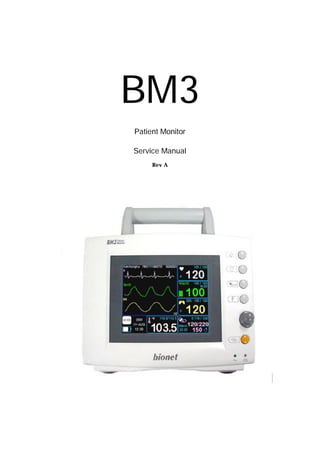
- 1. BM3 www.BIO2NET.com Revision A - 1 - BM3 Patient Monitor Service Manual Rev A
- 2. BM3 www.BIO2NET.com Revision A - 2 - Table of Contents 1. How to Reach Us … 2. General Precaution 3. Performance Specification 4. Equipment Overview 5. System Construction 6. System Inspection 7. Trouble Shoot 8. Exploded View 9. Circuit Diagram
- 3. BM3 www.BIO2NET.com Revision A - 3 - 1. How to Reach Us … The following are telephone numbers and addresses for contacting various service, product supplies and sales personnel Product and Purchase Inquiry Bionet Co., Ltd. Address #188-5, KiCOX venture center 501, Guro-dong, Guro-gu, Seoul, South Korea (ZIP 152-050) Overseas sales dept. Tel:++82-2-6300-6419 Service call Tel: ++82-2 –6300 - 6431 Technical support For any technical questions or problems on the equipment, call; Tel: ++82-2 –6300 - 6431
- 4. BM3 www.BIO2NET.com Revision A - 4 - Web site of Bionet URL : HTTP:// WWW.BIO2NET.COM ※ In the event of a malfunction or failure, contact Service Dept.Of Bionet Co., Ltd along with the model name, serial number, date of purchase and explanation of failure. Warranty l This product is manufactured and passed through strict quality control and thorough inspection. l Compensation standard concering repair, replacement, refund of the product complies with “ Consumer’s protection law” noticed by Economic Planning Dept. Warranty period is 2 year. l Warranty repair or replacement will be made by Bionet Service Center at no charge for warranty period if properly used under
- 5. BM3 www.BIO2NET.com Revision A - 5 - normal condition in accordance with the instructions for use. l Manufacturer or sales agency takes no responsibility for any kind of damage or breakdown that is caused by misuse and failure to maintain the equipment. 2. General Precaution Warning, Caution, Note l For a special emphasis on agreement, terms are defined as listed below in operation manual. Users should operate the equipment according to all the Warning and Caution. Warning : To inform that it may cause serious injury or death to the patient, property damage, material losses
- 6. BM3 www.BIO2NET.com Revision A - 6 - against the “Warning”sign. Caution: To inform that it may cause no harm in life but lead to injury against the “Caution”sign. Note : To inform that it is not dangerous but important for proper installation, operation, and maintenance of the equipment. General Precaution on Environment l Do not keep or operate the equipment in the environment listed below.
- 7. BM3 www.BIO2NET.com Revision A - 7 - Avoid placing in an area exposed to moist. Donot touch theequipment with wet hand . Avoid exposuretodirect sunlight Avoid placing in an area where there is a high variation of temperature. Operating temperature ranges from 10°C to 40°C. Operating humidity ranges from 30% to 85%. Avoid in the vicinity of Electric heater Avoid placing in an area where there is an excessive humidity riseor ventilation problem. Avoid placing in an area where thereisanexcessiveshockorvibration. Avoid placing in an area where chemicals are stored or where there is danger of gas leakage. Avoid being inserted dust and especially metal material into the equipment Do not disjoint or disassemble the equipment. Bionet Co.Ltd takes no responsibility for it Power off when the equipment is not fully installed. Otherwise, equipment could be damaged. General Precaution on Electric Safety Warning: Check the item listed below before operating the equipment.
- 8. BM3 www.BIO2NET.com Revision A - 8 - 1. Be sure that AC power supply line is appropriate to use. (AC 100 - 240V) 2.Be sure that the power source is the one supplied from Bionet. (DC 18V, 2.5A) 3.Be sure that the entire connection cable of the system is properly and firmly fixed. 4. Be sure that the equipment is completely grounded.(Otherwise, noise could result.) 5. The equipment should not be placed in the vicnity of electric generator, X- ray, broadcasting apparatus to eliminate the electric noise during operation. Otherwise, it may cause incorrect result. NOTE The Equipment should be placed far from generator, X-ray equipment, broadcasting equipment, or transmitting wires, so as to prevent the electrical noises from being generated during the operation, When these devices are near the Equipment, it can produce inaccurate measurements. For BM3, both independent circuit and stable grounding are essentially required. In the event that same power source is shared with other electronic equipment, it can also produce inaccurate output Warning Do not use the System for any monitoring procedure on a patient if the monitor is not working properly, or of it is mechanically damaged. Contact the hospital biomedical engineer, or your supplier
- 9. BM3 www.BIO2NET.com Revision A - 9 - NOTE BM3 is classified as follows. : - It is a class I type-CF Class equipment in terms of electrical shock prevention. It is not proper to operate this Equipment around combustible anesthetic or dissolvent. - The noise level is “B” Class according to the IEC/EN 60601-1 (Safety of Electric Medical Equipment), and the noise redemption is “B” Level according to the IEC/EN 60601-1-2 (Electromagnetic Compatibility Requirements). Equipment connection CAUTION In the hospital, doctors and patients are expose to dangerous, uncontrollable compensating currents. These currents are due to the potential differences between connected equipment and reachable conducting parts often in the medical rooms. The safety solution to the problem is accomplished with consistent equipment Maintenance and Cleaning Using various methods can clean BM3 and its accessories. Please follow the methods mentioned below to avoid unnecessary damage or contamination to the Equipment. In the event that harmful (unauthorized) materials are used for cleaning, the damaged or contaminated Equipment shall not be serviced without charges regardless of warranty period. Caution! Please check carefully both frame and sensor, after cleaning the Equipment, Do not use the Equipment that is worn out or damaged.
- 10. BM3 www.BIO2NET.com Revision A - 10 - At least once a month, clean and wipe off the frame by using the soft cloth after wetting it with lukewarm water and alcohol. Do not use lacquer, thinner, ethylene, or oxides, which could be harmful to the Equipment. Make sure both cables and accessories are free of dust or contaminants, and wipe them off with soft cloth wetted with lukewarm water(40℃ / 104℉), and at least once a week, clean them by using the clinical alcohol. Do not submerge the accessories under any liquid or detergent. Also, make sure any liquid not to penetrate into the Equipment or probe. Caution! Do not dispose single use probe to any hazard place, Always think about environmental contamination Caution! There is back-up battery on board inside system. When users dispose this chip. Please waste proper place for environmental protection CR2032 3.0Volt battery Warning: Check the electrodes of batteries before changing them. 3. Performance Specification Ease of use • Battery operation
- 11. BM3 www.BIO2NET.com Revision A - 11 - • Optional integrated strip chart recorder • mounting to a roll stand supports bedside availability Customization • Tabular and Graphical Trends • Compatible with Nellcor reusable and disposable SpO2 sensors Special Features • Direct DC input for transport needs • LAN data export interface • Nurse call alarm capability Monitor Environmental Specifications • Operating Temperature: 0°C to 50°C (32°F to 122°F) • Storage Temperature: - 20°C to 60°C (- 4°F to 140°F) • Operating/Storage Humidity: 5% to 95% RH, non-condensing • Operating Altitude: 0 to 3,048 m (0 to 10,000 ft.) Power • 18 VDC, 2.5 A max , Adapter Monitor Performance Specifications • Display: – LCD 5.7” color • Indicators – Up to 3 waves (ECG, SpO2, Respiration) – categorized alarms (3 priority levels) – visual alarm – heart rate tone – battery status – external power LED • Interfaces – DC input connector: 10 to 16 V DC, 3A max. – Defib Sync Output Signal Level: 0 to 5 V pulse
- 12. BM3 www.BIO2NET.com Revision A - 12 - Pulse Width: 100 ±10 ms Delay from R-wave peak to start of pulse: 35 ms, maximum Short circuit current: 15 mA Minimum required R-wave amplitude: 0.5 V – LAN digital output for transferring data to an external computer – nurse call • Battery (standard) – internal battery: sealed lead-acid – battery status indicator – Operating Time: 2.5 hours typical (fully charged battery) • Thermal Printer (Optional): – Speeds: 25, 50 mm/sec – Paper Width: 58 mm Graphical and Tabular Trends • Tabular Trends – Memory Storage: 24 hours – Data Interval: 1 minute – Display Interval: 1MIN, 5, 15, 30, 1HR Tabular Format: One table for all variables • Graphical Trends - Display Period: 30MINS, 60, 90, 3HRS, 6, 12 SpO2 Performance Specifications • % Saturation Range: 0% to 100% • Pulse Rate Range: 30 to 300 bpm • SpO2 Accuracy: 70% to 100% ± 2 digits, 0% to 69% unspecified • Pulse Rate Accuracy: ± 3 bpm NIBP Performance Specifications • Technique: oscillometric • Measurement Modes: – Manual:Single measurement - Auto:Automatic intervals of 1MIN,2,3,4,5,10,15,20,30,1HR,2,4,8 • Cuff Pressure Display: 30 to 300 mmHg • Blood Pressure Measurement Range:
- 13. BM3 www.BIO2NET.com Revision A - 13 - – Systolic: 60 to 250 mmHg – Mean Arterial Pressure: 45 to 235 mmHg – Diastolic: 40 to 220 mmHg • Pulse Rate Range: 40 to 200 bpm ECG Performance Specifications • Leads: 3 leads • Heart Rate Range: 30 to 300 bpm • Heart Rate Accuracy: ± 3 bpm • Bandwidth: 0.5 Hz to 40 Hz • Display Sweep Speeds: 25mm/sec • ECG Size (Sensitivity): 0.5, 1, 2, 4 mV/cm • Lead-Off Detection with display indicator • Pacemaker Detection Mode: Indicator on waveform display, user selectable • Differential Input Impedance: > 5 Mohm • Common Mode Rejection Ratio: > 90 dB at 50 or 60 Hz • Input Dynamic Range: ± 5 mVAC, ± 300 mVDC • Defibrillator Discharge: <5 s • Defibrillation Artifact Recovery Time: < 8 s Respirations Performance Specifications • Range: 5 to 120 breaths/min • Accuracy: ± 3 breaths/min • Display Sweep Speeds: 25mm/sec Temperature Performance Specifications • Range: 15°C to 45°C (59°F to 113°F) • Accuracy: 25°C to 45°C ± 0.2°C, 15 °C to 24°C ± 0.3°C • Compatible with YSI Series 400 Temperature Probes Accessories included: - 3-lead patient cable 1ea - electrodes 10ea
- 14. BM3 www.BIO2NET.com Revision A - 14 - - NIBP tubing, 3 m long 1ea - Adult cuff, 25-35 cm, reusable 1ea – SpO2 sensor extension cable(2 m) 1ea – SpO2 sensor, reusable 1ea – DC adapter, 18VDC, 2.5A 1ea - Temperature probe Surface/Skin, reusable(OPTION) – rolls of paper. (OPTION) - 5-lead patient cable(OPTION) 4. Equipment Overview Overview of the Product BM3 monitor is a product used for monitoring biological information and
- 15. BM3 www.BIO2NET.com Revision A - 15 - occurrence of a patient. Main function ns of the product include displaying information such as ECG, respiration, SpO2, NIBP and temperature on its LCD screen and monitoring parameter, and alarming. It also prints out waves and parameters via a printer. Features of the Product BM3 is a small-size multifunctional monitoring equipment for a patient designed to an easy usage during movement. It features devices for auto power supply (DC 10V-16V) and DC power supply (DC 18V) as well as installing its handle to the patient’s bed. The equipment also measures major parameters such as ECG, SpO2, NIBP, temperature and pulse, displaying it on a 5.7-inch color LCD screen. It also enables users to check waves and parameters and other vital signs of a patient via the 58mm thermal printer and monitor the patient by the remote-controlled alarm system. It also enables to build a central monitoring system by linking devices used for separate patients so that one can monitor several patients at a time. Warning In order to avoid electrical shock, do not open the cover. Disassembling of the Equipment have to be done only by the service personnel authorized by BiONET Co. Ltd.
- 16. BM3 www.BIO2NET.com Revision A - 16 - BiONET Co. Ltd. Warning Users must pay attention on connecting any auxiliary device via LAN port or nurse calling. Always consider about summation of leakage current, Please check if the auxiliary device is qualified by IEC 60601-1, or consult your hospital biomedical engineer Features of Main Body SILENCE ALARM KEY PRINT GO/STOP KEY NIBP GO/STOP KEY FUNCTION KEY TRIM KNOB CONTROL KEY POWER KEY Front
- 17. BM3 www.BIO2NET.com Revision A - 17 - Protective Ground Terminal DC Power Input Port Defib Sync RJ45 LAN Port RS-232C Serial Port /Nurse Call Back ECG Probe Connecter NIBP Probe Connecter SpO2 Probe Connecter TEMP Probe Connecter ▲ Right side ▼ Left side
- 18. BM3 www.BIO2NET.com Revision A - 18 - PRINTER Accessories ECG Cable ECG wire SpO2 Cable SpO2 Extention cable
- 19. BM3 www.BIO2NET.com Revision A - 19 - (option) Temperature Cable NIBP CUFF TEMP(OPTION) Equipment Symbols ! ATTENTION : Consult accompanying documents ♥ TYPE CF APPLIED PART : Insulated (floating) applied part suitable for intentional external and internal application to the patient including direct cardiac application. “Paddles” outside the box indicate the applied part is defibrillator proof. Medical Standard Definition : F-type applied part (floating/insulated) complying with the specified requirements of IEC 60601-1/UL 2601-1/CSA 601.1 Medical Standards to provide a higher degree of protection against electric shock than that provided by type BF applied parts. TYPE BF APPLIED PART : I Insulated (floating) applied part suitable for intentional external and internal application to the patient excluding direct cardiac application. “Paddles” outside the box indicate the applied part is defibrillator proof.
- 20. BM3 www.BIO2NET.com Revision A - 20 - Medical Standard Definition : F-type applied part (floating/insulated) complying with the specified requirements of IEC 60601-1/UL 2601-1/CSA 601.1 Medical Standards to provide a higher degree of protection against electric shock than that provided by type B applied parts. Equipotentiality PAPER RS-232 LAN AUX CONNECTOR DC INPUT INDICATOR - + BATTERY OPERATION INDICATOR +- DC 18V 2.5A DC INPUT CONNECTOR
- 21. BM3 www.BIO2NET.com Revision A - 21 - 5. System Construction Block Diagram
- 22. BM3 www.BIO2NET.com Revision A - 22 - ANALOG1 (ECG, RESP.) PRINTER BOARD POWER DIGITAL BOARD EXT. BOARD SAFETY BOARD (POWER ON/OFF, NIBP FOR SAFETY FUNCTION) ANALOG2 (SpO2, NIBP, TEMP) Digital Board
- 23. BM3 www.BIO2NET.com Revision A - 23 - BACKUP MEMORY (SRAM) MEMORY (ROM(HY29LV160), SDRAM(K4S) LCD (BUFFER, LCD BIAS VOLTAGE GENERATOR) DC TO DC CONVERTER (3.3V, 2.5V GENERATOR) LAN CONTROLLER (CS8900) CPU (S3C44BOX) 3V Lion BATTERY LCD SIGNAL LCD CONTRAST CONTROL 5V 7.2V GND FROM POWER BUSCONTROL SIGNAL DATABUS ADDRESSBUS 3V BATTERY POWER 3VBATTERY POWER 3VBATTERY POWER 3.3V 2.5V TO PRINTER BOARDTO SAFETY BOARD SERIAL CONTROLLER (ST16C2550) TO ANALOG BOARDS WATCHDOG TIMER RESET RESET CLEAR CLEAR TIMEROUT CPUSERIAL0 CPUSERIAL1 SERIAL1 SERIAL0 TO AUX PORT SPIBUS TO EXT. BOARD Power components Power boards receives +5V, then creates 3.3V and 2.5V through the direct- direct rectifier.
- 24. BM3 www.BIO2NET.com Revision A - 24 - CPU components Samsung’s S3C44B0X is installed operating at the 3.5 times speed of 18.432MHz, 64.512MHz. The CPU includes the STN LCD CONTROLLER; Real Time Clock is installed inside allowing the activation of the interior clock, if the crystal of 32.768KHz and power are supplied. Memory components Consists of the ROM 2MByte (Hynix HY29LV160BT) and RAM 8MByte (Samsung K4S641632); by moving program images of the ROM to RAM commands are run. BACKUP Memory component Consists of the 128KByte SRAM and theSRAM BACKUP CONTROLLER; Lion Batteryof 3V is required. Data needed even when the power is turned on is saved. LCD components Consists of the signal buffer, the DAC(Digital-Analog Conver), the Op Amp and the DC-DC Converter. DC-DC Converter converts +5V into +28V then supplies power to the Op Amp. The Op Amp multiplies the output of the DAC(0~2V) by 15 times. The output of the Op Amp equals to the LCD Bias Voltage. +3.3V signals from the CPU becomes +5V signals through the buffer, then is supplied to the LCD. LAN Controller Consists of Cirrus Logic’s CS8900 Ethernet Controller and supports 10Base-T. 3V Lion Back-up power for CPU’s RTC and SRAM. WATCH DOG TIMER Resets the system should there be any failure in the system operation; saves system settings in the interior memory
- 25. BM3 www.BIO2NET.com Revision A - 25 - Serial Controller Communicates with the analog board through two serial channels. Safety Board Cuts power off to the monitor and the pump in case of over pressure/over time to stablize NIBP; controls the overall power by receiving signals from power switch. DC- DC CONVERTER CPU PRESSURE SENSOR RELAY (FOR MOTOR, PUMP POWER) DC INPUT (+10.5 ~ +18) +5V RELAYON/OFFSIGNAL SENSOR DATA SERIAL (TO DIGITAL BOARD) POWER ON/OFF SIGNAL POWER SWITCH Printer Board Connects to the Digital Board; generates the printer and the motor controlling signals using CPLD (Complete Program Logic Device)
- 26. BM3 www.BIO2NET.com Revision A - 26 - CPLD FIFO MOTOR DRIVER DATA BUS (FROM DIGITAL BOARD) DATA BUS MOTOR CONTROL SIGNAL +7.2V (FROM DIGITAL BOARD) THERMAL PRINTER SIGNAL (TO PRINTER) MOTOR SIGNAL (TO MOTOR) Ext. Board Consists of the Speaker drive circuit, exterior serials and Dsync outputs
- 27. BM3 www.BIO2NET.com Revision A - 27 - D SYNC OUTPUT CIRCUIT ISOLATED POWER RS- 232 SERIAL D RIVER AUDIO AMP D AC + 5V SERIAL (FROM DIGITAL BOARD ) DSYNC IN (FROM D IGITAL BOARD ) SPI BUS (FROM D IGITAL BOARD ) SERIAL OUT (TO 9PIN DSUB CONNECTOR) D SYNC OUT (TO 6PIN DIN CONNECTOR) SPEAKER Power Board Supplys power for each board while recharging. +5V REGURATOR +7.2V REGURATOR +9.5V REGURATORCHARGER CIRCUIT AC-DC ADAPTER (18V/ 2.5A) BATTERY (12V, 2Ah) AC 100~220V, 5-~60Hz, 1.2A TO DIGITAL BOARD, TO ANALOG BOARDS TO DIGITAL BOARD TO ANALOG BOARDSTO SAFETY BOARD
- 28. BM3 www.BIO2NET.com Revision A - 28 - Power Supply Fuse An A.C Fuse of 250V/1.6A is built in the adapter. BM3’s POWER Borad is protected by Fuse 5A/125V connected with a Battery protection Fuse 5A/125V which protects the product. 6. System Inspection PRINTER Inspection contents - Pinter status - No Paper - Set the Speed - Pinter noise
- 29. BM3 www.BIO2NET.com Revision A - 29 - Inspection standards - Detect the paper - Normal operation in the speed 25mm/s, 50mm/s - Noise when you use print - Clear output Inspection procedure - Check the detection of the paper when the paper is in the device or not - Check the speed of the printing after changing the printing speed - Check the noise when print is working - Check the status of the print-output ECG Inspection contents - Lead Select - Lead Fault - Gain 1mV - Pace Detect - Noise Inspection standards - The alteration of the setting values of the lead(3 lead: I,II,III) - Detect the each lead fault - 10hz sine wave Amp : 10mm +/- 1mm - Detect the pace maker signal - 1mm Inspection procedure
- 30. BM3 www.BIO2NET.com Revision A - 30 - - Check the alteration after connecting the 5 leads ecg cable to simulator - Check the lead fault in the each lead - Check the gain of the printer-output after setting the 10hz sine wave in the simulator - Check the letter P in the display after setting the pace mode in the simulator - Check the size of the base noise after connecting the human body RESPERATION Inspection contents - Gain 1Ω - Noise Inspection standards - The wave size in the LCD display and printer should be within 10mm +/- 1 mm. - The wave size of the noise in the LCD display and printer should be within 2 mm. Inspection procedure - Check the gain of the printer-out by using the simulator ; 1Ω - Check the noise by using the simulator ; 0Ω, display x10 SpO2 Inspection contents
- 31. BM3 www.BIO2NET.com Revision A - 31 - - Precision - No finger - Lead Fault Inspection standards - Amp. 0.3 , %spo2 96: +/- 2 - Detect the NO FINGER - Detect the lead fault Inspection procedure - Check the error by using the simulator ; Amp 0.3, % 96 - Check the message when you don't put the finger in the Probe - Check the message when the spo2 connector is disconnected from the main device TEMP Inspection contents - Precision - Lead Fault Inspection standards - The temp. 20, 37°C : +/- 0.1°C - Detect the lead fault Inspection procedure - Check the error after setting temp. by using the precision -resistance box
- 32. BM3 www.BIO2NET.com Revision A - 32 - - Check the message when the temp connector is disconnected from the main device NIBP Inspection contents - Precision - Set the Zero - Operate the OVP - Auto measurement Inspection standards - The mean values after measuring 5 times : +/- 5mmHg - Set the normal zero - adult : 290mmHg - Auto measurement in the auto-mode Inspection procedure - Check the values 5 times in the arm cuff mode by using the simulator ; 120/93/80, 200/196/180 - Set the zero in the device - Check the OVP operation by using the simulator ; 290mmHg - Check the operation in the interval 1 minute ALARM Inspection contents - Control the volume of the sound - Operate the alarm
- 33. BM3 www.BIO2NET.com Revision A - 33 - Inspection standards - Control the volume of the sound - The alarm mode according the setting values & situation Inspection procedure - Check the volume level of the sound - Check the alarm sound after changing the ECG HR Electrical safety Inspection contents - Inspect the voltage - Inspect the patient leakage current Inspection standards - Between the power teminals :1500Volt - Between the power and ECG electrode : AC4000Volt - Between the power and temp : AC4000Volt - Patient leakage current should be under 50uA Inspection procedure - Check the insulation after giving the AC1500Volt during 60 sec. between power teminals - Check the insulation after giving the AC4000Volt during 60 sec. between power teminals and terminals of the ECG electrode - Check the insulation after giving the AC4000Volt during 60 sec. between power teminals and the temp sensor - Check the leakage current after connecting the all sensor
- 34. BM3 www.BIO2NET.com Revision A - 34 - 7. Trouble Shoot 1. Noise in ECG The patient's skin is extremely dry YES NO Apply ECG gel or water to the area of contact then use the electrode. The electrode is in poor conditions The Cable(lead wire) is disconnected Repair the ECG B/D NO NO YES YES Replace the electrodes (Use CE compatible products) Replace lead wires - Gel is dry. - Electrodes does not stick well to skin The extension cables are disconnected YES NO Replace extension cables The Finger probe is in bad conditions? NO YES Replace the finger probe Connecters of the equipments are in bad conditions?
- 35. BM3 www.BIO2NET.com Revision A - 35 - 3.Temp malfunction 4. NIBP malfuction Air leaks from the hose connector or cuff YES NO Replace the hose or cuff Repair NIBP B/ D The probe is in bad conditions YES NO Replace the probe Repair the Temp B/ D 5. Abnormality in NIBP measurements The measurements appear lower YES NO Loosen the cuff during diagnosis There is a delay in measuring Repair the NIBP B/ D NO YES Tighten the cuff during diagnosis The patent moved while measuring YES NO Make sure the patient stay still during diagnosis
- 36. BM3 www.BIO2NET.com Revision A - 36 - 6. Failure in battery recharge (the battery does not fully recharge in 6 hours or more) 7. Power failure The battery voltage is lower than 5v YES NO Replace the battery Repair the power B/D "Admit" has been selected in the Menu YES NO Execute the "Admit" function (No data will be stored during battery discharge) The Digital B/D (dig) Battery has lower than 3v Repair the Dig B/D NO YES Replace the battery (3volt) The output voltage of the adapter is 18v YES NO Replace the adapter (the battery will not be charged at the rate lower than 17v) YES NO Replace the adapter Repair the power B/D The adapter connector is in bad conditions YES NO Replace the adapter The output voltage of the adapter is lower than 18v
- 37. BM3 www.BIO2NET.com Revision A - 37 - 9. Periodic noises 10. Print failure Display lead fault message appears YES Turn functions not in use off (More- Display - Set para) Repair the accompanying equipment All alarm has been turnd off YES NO YES NO Reverse the paper face Repair the printer and printer B/ D The paper tray cover is properfly shut YES NO Shut the cover tight The printing face of paper has been reversed The printer functions abnormally YES NO Replace the printer NO
- 38. BM3 www.BIO2NET.com Revision A - 38 - 8. Exploded View
- 39. BM3 www.BIO2NET.com Revision A - 39 - 9. Circuit Diagram Analog1 b/d, digital part TP8 TP 1 1 + C 6 47U F /16V + C 11 100U F /35V TOU T3 U 3 H C PL4502_020 1 2 3 45 6 7 8 N C 1 AN C A N C 2GN D 1 OU T EN VC C 1 5VA R XB R 19 470/J BC 6 0.1U F /Z 5VA AC P1 AGN D D 1 ? AGN D SPI_SD O TXB MALE R 34.7K/J BC 2 1U F /Z AC P D 4 MBR S130LT3 C 10 0.1U F /Z VC C 9.1 D 6 MBR S130LT3 SpO2_SIG R ESET AC P Y 1 18.432MH z R 6 10/J W D T_OU T AGN D D GND VC C 9.1 SPI_SC K W D T_OU T D 3 MBR S130LT3 5VA U 5 KA7805R 1 2 3 VIN A G N D VOU T C LKOU T + C 12 100U F /35V SPI_C S VIN AGN D U 1 PIC 16F874PQ 1 2 3 4 5 6 7 8 9 10 11 14 15 16 17 18 19 20 21 22 23 24 25 26 27 28 29 30 31 32 35 36 37 38 39 40 41 42 43 44 R C 7/R X/D T R D 4/PSP4 R D 5/PSP5 R D 6/PSP6 R D 7/PSP7 AGN D 2 VD D 2 R B0/IN T R B1 R B2 R B3 R B4 R B5 R B6 R B7 MC LR /Vpp R A0/AN 0 R A1/AN 1 R A2/AN 2 R A3/AN 3/VR EF R A4/TOC KI R A5/AN 4/SS R E0/R D /AN 5 R E1/W R /AN 6 R E2/C S/AN 7 VD D 1 AGN D 1 OSC 1/C LKIN OSC 2/C LKOU T R C 0/T1OSO/T1C KI R C 1/T1OSI/C C P2 R C 2/C C P1 R C 3/SC K/SC L R D 0/PSP0 R D 1/PSP1 R D 2/PSP2 R D 3/PSP3 R C 4/SD I/SD A R C 5/SD O R C 6/TX/C K VC C 3.3 AGN D 5VA EN ABLE R 4 100K/J S_B R XD U 22F MM74H C 14 1312 14 7 -5VA U 4 H C PL4502_020 1 2 3 4 5 6 7 8 N C 1 AN C A N C 2 GN D 1 OU T EN VC C 1 D GN D VC C9.1 ISP_D AT ABP D GN D D GN D ISP_C LK BC 7 0.1U F /Z R 15 10/J R 70 2K/J C 48 ? AGN D R XB C 49 ? SPI_SD O R 16 10/J 5VA + C 17 100U F /35V SPI_SD I TOU T3 R 20 1K/J Q2 MMBT3904 2 1 3 R 14 1K/J D 5 MBR S130LT3 5VA R 5 10K/J C 1 0.1U F /K R ESET S1 ? AGN D TXD S2 ? U 22D MM74H C 14 9 8 14 7 U 22C MM74H C 14 5 6 14 7 D GN D S_A SPI_SD I AC P1 BC 8 0.1U F /Z BC 1 0.1U F /Z 5VA VC C5.0 Q5 MMBT3904 2 1 3 + C 14 10UF/35V BC 5 0.1U F /Z R 7 4.7K/J C 2 10PF/K AGN D BC 3 0.1U F /Z ISP_D AT 5VA R 18 1K/J BC 4 1U F /Z U 6 KA79M05R 3 1 2 VOU T A G N D VIN D GN D VC C 3.3 SPI_SC K VC C 5.0 C 13 0.1U F /Z + C 16 100U F /35V 5VA TEMP1 T1 EPC 17-TP1 1 3 10 8 6 2 4 5 7 9 BC 16 0.1U F /Z C LKOU T C 15 0.1U F /Z R 8 330/J AGN D Q3 IR F U 020A 1 2 3 VIN T_R EF D EV_SW 5VA IR JP1 PH 11-60-D R -GA 2 4 6 8 10 12 14 16 18 20 22 24 26 28 30 32 34 36 38 40 42 44 46 48 50 52 54 56 58 60 1 3 5 7 9 11 13 15 17 19 21 23 25 27 29 31 33 35 37 39 41 43 45 47 49 51 53 55 57 59 C 3 10PF/K U 18 ? 1 2 3 4 5 R ESET GN D MR W D I VD D RESET J1 5267-5 1 2 3 4 5 SPI_C S R 17 1.8K/JAGN D AGN D VC C 3.3 U 2 AD S8344E 1 2 3 4 5 6 7 8 9 1011 12 13 14 15 16 17 18 19 20 C H 0 C H 1 C H 2 C H 3 C H 4 C H 5 C H 6 C H 7 C OM /SH D NVR EF VC C1 AGND 2 AGND 1 D OUT BU SY D IN /C S D C LK VC C2 Q1 IR F U 9014 1 3 2 AGN D D GN D 5VA TXB U 22E MM74H C 14 1110 14 7 ABP D EV_SW + C 7 10UF/35V DEV_MODE R 12 470/J AGN D VC C 7.5 ISP_C LK U 22B MM74H C 14 34 1 4 7 R ED AGN D VC C3.3 R 13 1K/J AGND AGN D R XD R 1 ? Q4 MMBT3906 2 1 3 R 2 220/J VC C7.5 D EV_SW U 22A MM74H C 14 12 1 4 7 C 8 0.1UF/Z 5VA TXD C 9 0.1U F /Z
- 40. BM3 www.BIO2NET.com Revision A - 40 - Analog1 b/d, Nibp part R25 0/J C26 0.1U F/J ACP + - U9B MCP604ISL 5 6 7 4 1 1 U7 MPX5050GP 1 2 3 4 5 6 7 8 Vout AGND 5VA NC1 NC2 NC3 NC4 NC5 R21 10K/J R22 10K/J AGND AGND + - U9D MCP604ISL 12 13 14 4 1 1 AGND + - U9A MCP604ISL 3 2 1 4 1 1 C20 1UF/Z AGND R28 1K/J 5VA TP4 TP 1 1 C30 1UF/Z AGND BC14 0.1UF/Z AGND C18 100NF /J C 29 1UF/ J/MULTI R30 1K/F C22 0.1U F/Z 5VA C24 47NF/J AGND R29 51K/J TP5 TP 1 1 5VA R27 200K/F AGND C28 0.1UF/J ABP + - U9C MCP604ISL 10 9 8 4 1 1 R31 1K/J
- 41. BM3 www.BIO2NET.com Revision A - 41 - Analog1 b/d, SpO2 part C35 0.1UF/J R 33 3.3K/J U 14 MM74H C4052 12 14 15 11 1 5 2 4 6 10 9 13 3 16 8 7 X0 X1 X2 X3 Y0 Y1 Y2 Y3 IN H A B X Y VD D AGND VEE + - U 17C TL064 10 9 8 4 11 5VA BC 10 0.1UF/Z R65 47K/F L1 1MH J3 5267-6 1 2 3 4 5 6 -5VA R41 3.3K/J 5VA IR R60 1K/J R 66 270K/J R 71 47/J C47 10NF/J 5VA AGN D AGN D R 62 2.7M/J R 61 270K/J - + U11B MC P602ISN 5 6 7 8 4 C 42 470PF/K R63 1K/F AGND AGND Q11 MMBT3904 2 1 3 5VA Q7 MMBT3906 2 1 3 R55 4.7K/F R 50 270K/J BC13 0.1U F/Z R44 10/J Q9 MMBT3904 2 1 3 R 56 1M/J 5VA -5VA R 46 330/J BC 11 0.1UF/Z C37 47PF/J R48 7.5K/J + - U 17B TL064C DR 5 6 7 4 11 AGND AGND -5VA 5VA AGN D AGN D 5VA R 54 10K/F U21 B2K 1 2 3 4 5 6 IN1 NC 1 OUT1 OUT2 NC 2 IN2 -5VA AGN D TP2 TP 1 1 R39 68K/J AGN D R 35 3.3K/J AGN D IR U20 B2K 1 2 3 4 5 6 IN1 N C1 OUT1 OUT2 NC 2 IN2 + C50 10UF/35V AGND 5VA R 36 10K/J Q6 MMBT3906 2 1 3 TP1 TP 1 1 AGN D C39 0.1UF(1J104J) AGND + - U17D TL064C DR 12 13 14 4 1 1 IR 5VA Q13 MMBT3904 2 1 3 R34 10/J R42 10K/J AGN D R47 470/J C32 0.1UF/Z R59 47K/F 5VA SpO2_SIG R38 22K/J 5VA R ED + C 33 10UF/35V R43 10/J 5VA R 45 330/J Q8 MMBT3904 2 1 3 R 67 2.7M/J RED + C 34 10U F/35V - + U 11A MC P602ISN 3 2 1 8 4 AGND -5VA - + U13B TL062C DR 5 6 7 8 4 C43 10NF/J -5VA U15 MM74H C4052 12 14 15 11 1 5 2 4 6 10 9 13 3 16 8 7 X0 X1 X2 X3 Y0 Y1 Y2 Y3 INH A B X Y VDD AGND VEE Q10 MMBT3904 2 1 3 R52 1K/F AGN D R40 3.3K/J S_A C46 0.1UF(1J104J) C 40 0.1U F/Z + - U17A TL064 3 2 1 4 1 1 R64 1K/F D 7 LM431ACMX 6 1 8 C41 1N F/K AGN D S_B BC12 0.1U F/Z AGND AGN D AGND 5VA U19 B2K 1 2 3 4 5 6 IN1 N C1 OUT1 OUT2 NC 2 IN2 EN ABLE AGND AGN D R57 10K/F R58 1K/J R 51 2.2K/J AGND - + U 13A TL062C DR 3 2 1 8 4 RED AGN D C 45 0.1U F/Z AGND AGND C 44 0.1U F/Z C 38 0.1U F/Z -5VA R 37 10K/J R49 1K/F 5VA 5VA R 32 10/J R53 47K/F Q12 MMBT3904 2 13 -5VA + C 31 10UF/35V
- 42. BM3 www.BIO2NET.com Revision A - 42 - Analog1 b/d, Temp part 5VA TP6 TP 1 1 AGND R11 100K/F AGND AGND U23 B2K 1 2 3 4 5 6 IN1 NC1 OUT1 OUT2 NC2 IN2 C4 0.1UF/K J2 5267-2 1 2 R10 1070/B D2 ? 6 1 8 AGND T_REF R9 ? TEMP1 C5 0.1UF/K
- 43. BM3 www.BIO2NET.com Revision A - 43 - Analog2 b/d, Digital part AGND_1 R 79 470/J L_R DEV_SW L_F + C37 10UF/35V VCC 3.3 ISP_DAT R83 10/J C 40 0.1UF/Z VC C9.1 DAMPER1 SPI_SD I C 34 10PF/K MALE VCC 3.3 +5VA_1 D30 MBR S130LT3 BC9 0.1UF +5VA_1 C39 0.1UF/Z R82 10/J AGND_1 R 75 4.7K/J C45 0.1UF/Z R 85 1K/J DGND U11D 74HC 14 9 8 14 7 S1 ? VCC5.0 VCC7.5 Q5 MMBT3906 2 1 3 WDT_OU T ISP_CLK T1 EPC17-TP1 1 3 10 8 6 2 4 5 7 9 R78 10/J WD T_OUT R74 100K/J BC5 0.1UF/Z AGN D_1 BC4 1UF/Z AGN D_1 C83 ? AGND_1 VCC7.5 +5VA_1 U 11C 74H C14 5 6 14 7 U9 PIC16F874PQ-20 1 2 3 4 5 6 7 8 9 10 11 14 15 16 17 18 19 20 21 22 23 24 25 26 27 28 29 30 31 32 35 36 37 38 39 40 41 42 43 44 R C7/RX/D T RD4/PSP4 RD5/PSP5 RD6/PSP6 RD7/PSP7 Vss VD D RB0/IN T RB1 RB2 RB3 RB4 RB5 RB6 RB7 MC LR/Vpp R A0/AN 0 R A1/AN 1 R A2/AN 2 RA3/AN 3/VREF R A4/TOCKI RA5/AN4/SS RE0/RD/AN 5 R E1/WR/AN 6 RE2/CS/AN 7 VD D Vss OSC1/CLKIN OSC2/CLKOU T RC0/T1OSO/T1CKI RC 1/T1OSI/CCP2 RC 2/CCP1 RC3/SCK/SC L RD0/PSP0 RD1/PSP1 RD2/PSP2 RD3/PSP3 R C4/SD I/SD A RC5/SDO RC 6/TX/C K + C42 100UF/35V AGND _1 LEAD _L D31 MBRS130LT3 RESP_SIG1 DAMPER2 L_R C _SEL AGND_1 C LKOUT BC 3 1U F/Z +5VA_1 U23B 74HC14 34 14 7 LD1 BC2 0.1UF/Z R70? +5VA_1 BC 1 0.1UF/Z TOU T3 R77 2K/J U11F 74HC 14 1312 1 4 7 D29 MBRS130LT3 SPI_SD O SPI_SD I BC 8 0.1UF/Z AGND _1 DGND L_C TXA Q2 IRFU 9014 1 2 3 C82 ? AGND_1 LEAD _C ISP_CLK TXD +5VA_1 AGND_1 C33 1U F/Z +5VA_1 LD2 TXA SPI_SD O RESET VCC9.1 + C41 100UF/35V L_L U11A 74HC14 12 1 4 7 CABLE_SEL R72 4.7K/J R81 1K/J R84 1.8K/J RXD +5VA_1 ISP_DAT R76 330/J +5VA_1 DGND VCC9.1 VCC3.3 S2 ? BC6 0.1UF/Z AGN D_1 Q4 IRFU 020A 1 2 3 DGND + C44 10UF/35V AGN D_1 R 86 470/J D32 MBR S130LT3 RESP_114KHz LEAD _F TXD R XA -5VA_1 U23A 74HC14 12 14 7 BC7 0.1UF/Z U11E 74HC 14 1110 1 4 7 R 80 1K/J U23E 74HC14_5 1110 14 7 AGND_1 SPI_SC K L_F U23F 74HC14 1312 14 7 U 11B 74H C14 34 1 4 7 AGND_1 R71 220/J c28 0.1UF/Z RESP_ON SPI_CS P_D R 73 10M/J JP1 PH11-60-DR -GA 2 4 6 8 10 12 14 16 18 20 22 24 26 28 30 32 34 36 38 40 42 44 46 48 50 52 54 56 58 60 1 3 5 7 9 11 13 15 17 19 21 23 25 27 29 31 33 35 37 39 41 43 45 47 49 51 53 55 57 59 DEV. MODE C35 10PF/K AGN D_1 C 43 0.1UF/Z R87 1K/J AGN D_1 + C36 47UF/16V AGND_1 J2 5267-5 1 2 3 4 5 AGND _1 Y 1 18.432MHz RESET U15 KA78M05R 1 2 3 VIN G N D VOUT + C46 100UF/35V AGN D_1 +5VA_1 AGND_1 D28 ? LD0 U14 ADS8344E 1 2 3 4 5 6 7 8 9 1011 12 13 14 15 16 17 18 19 20 CH0 CH1 CH2 CH3 CH4 CH5 CH6 CH7 COM /SHDNVR EF VC C GND GND DOU T BU SY DIN /CS DCLK VC C U 12 H CPL4502_020 1 2 3 4 5 6 7 8 N.C AN CA N.C GND OUT EN VCC VIN VCC5.0 U23D 74HC14 98 14 7 +5VA_1 CLKOU T U23C 74HC14 56 1 4 7 AGN D_1 L_C AGND_1 AGN D_1 RXA Q6 MMBT3904 2 1 3 ECG_SIG PACE_DET DEV_SW CAL TOUT3 AGND _1 VCC3.3 U13 ? 1 2 3 4 5 RESET GN D MR WDI VDD + C47 100UF/35V VIN R XD C_SEL D GND SPI_SC K Q3 MMBT3904 2 1 3 RESET DGND C 38 0.1UF/Z AGND_1 SPI_CS U 10 H CPL4502_020 1 2 3 45 6 7 8 N .C AN CA N .CGND OUT EN VC C LEAD _R L_L LD[0..2] +5VA_1 U16 KA79M05R 3 1 2 VOUT G N D VIN +5VA_1 DEV_SW P_D
- 44. BM3 www.BIO2NET.com Revision A - 44 - Analog2 b/d, ECG part AGND_1 R29 1K/J R52 200K/J AGND_1 R22 10K/F C2 0.1UF/Z D13 SA170CA AGND_1 R124 510/J LD2 +5VA_1 AGND_1 -5VA_1 AGND_1 R53 200K/J R20 10K/F AGND_1 LEAD_C C12 470PF/K C25 0 ohm AGND_1 +5VA_1 +5VA_1 D25 SA170CA AGND_1 R11 100K/J RL V- - + U1D TL064CDR 12 13 14 4 1 1 LA AGND_1 +5VA_1 U3 74HC4053 12 13 2 1 5 3 6 11 10 9 14 15 4 16 8 7 X0 X1 Y0 Y1 Z0 Z1 INH A B C X Y Z VDD VSS VEE +5VA_1 AGND_1 +5VA_1 C94 100NF/J U7 74HC4051 13 14 15 12 1 5 2 4 6 11 10 9 3 16 8 7 X0 X1 X2 X3 X4 X5 X6 X7 INH A B C X VDD VSS VEE -5VA_1 AGND_1 C1 0.1UF/Z U5 74HC4051 13 14 15 12 1 5 2 4 6 11 10 9 3 16 8 7 X0 X1 X2 X3 X4 X5 X6 X7 INH A B C X VDD VSS VEE R27 100K/J R30 2M/J R56 30K/J -5VA_1+5VA_1 TP2 D2 BAV99 C74 0.1UF/Z - + U4D TL064CDR 12 13 14 4 1 1 R39 10K/F -5VA_1 -5VA_1 R62 100K/J R118 100K C24 10NF/K LD1 C8 0.1UF/Z AGND_1 +5VA_1 C27 0.1UF/Z R23 10K/F R13 10M/J R12 10M/J C31 0.1UF/Z R58 10K/F DAMPER1 C R15 10M/J C86 1NF/J C15 270PF/J +5VA_1 LEAD_L LD0 TP1 R3 1K/F AGND_1 100K/J R17 R57 10K/ F C6 470NF/J(474K63) -5VA_1 R55 2.2M/J -5VA_1 AGND_1 R10 10M/J D18 SA170CA LEAD_F R32 10K/F R40 10K/F R6 100/F V+ -5VA_1 R41 10K/F R21 ? +5VA_1 LD2 AGND_1 DAMPER2 J1 5267-13 1 2 3 4 5 6 7 8 9 10 11 12 13 R42 2.2M/J SEL R33 100K/J C29 470P/K R8 10M/J AGND_1 AGND_1 C22 470PF/K R14 10M/J AGND_1 +5VA_1 R7 10M/J C23 68PF/J R36 10K/F R119 4.7K/J/1/2W LL_R AGND_1 R43 10K/F R121 100K/F C20 10NF/J R49 100K/J ECG_SIG D3 BAV99 C26 10NF/J AGND_1 C95 47NF/J -5VA_1 + C30 10UF/35V R48 100K/J C3 470PF/K AGND_1 +5VA_1 R26 10K/F R2 150K/F R59 0 R5 100K/J C16 470PF/K +5VA_1 R4 24K/J RESP_DIS R122 20K/F R9 10M/J +5VA_1 R136 22K/F R1 100K/ F C11 0.1UF/Z R51 10K/J - + U4A TL064CDR 3 2 1 4 1 1 - + U6A TL064CDR 3 2 1 4 11 AGND_1 +5VA_1 AGND_1 Q1 MMBT3904 2 1 3 C14 0.1UF/Z C18 0.1UF/Z R28 10K/J AGND_1 LL LEAD_R LD0 R35 200K/F C10 0.1UF/Z C9 1NF/J LD1 R31 10K/F AGND_1 AGND_1 -5VA_1 PACE_DET R123 100K/F RA +5VA_1 - + U6D TL064CDR 12 13 14 4 1 1 SHIELD AGND_1 R63 47K/J - + U1B TL064CDR 5 6 7 4 1 1 R46 10K/J -5VA_1- + U1C TL064CDR 10 9 8 4 1 1 U2 74HC4051 13 14 15 12 1 5 2 4 6 11 10 9 3 16 8 7 X0 X1 X2 X3 X4 X5 X6 X7 INH A B C X VDD VSS VEE C4 0.1UF/Z D7 BAV99 R16 3.3K/J D4 SA170CA R64 4.7K/J +5VA_1 C21 270PF/J LD[0..2] - + U6C TL064CDR 10 9 8 4 1 1 - + U4B TL064CDR 5 6 7 4 1 1 +5VA_1 -5VA_1 AGND_1 C85 1NF/J R50 27K/J R19 10K/F AGND_1 R47 200K/J R120 510/J RA_R D9 BAV99 C72 0.1UF/Z AGND_1 AGND_1 CAL LD1 - + U1A TL064CDR3 2 1 4 1 1 C13 270PF/J -5VA_1 D1 LM431 6 1 8 C75 100P/J C17 10NF/K AGND_1 AGND_1 R44 100K/J C71 0.1UF/Z - + U6B TL064CDR 5 6 7 4 1 1 - + U4C TL064CDR 10 9 8 4 11 AGND_1 R45 10K/F D5 BAV99 R18 10K/F D8 SA170CA -5VA_1 AGND_1 R135 22K/F AGND_1 C73 0.1UF/Z AGND_1AGND_1 AGND_1 AGND_1 CABLE_SEL C5 270PF/J C84 10NF/K AGND_1 AGND_1 R34 2K/F C19 0.1UF/Z LD[0..2] AGND_1 R38 100K/J +5VA_1 LD0 R24 10K/F -5VA_1 AGND_1 TP3 AGND_1 LD2 D6 BAV99
- 45. BM3 www.BIO2NET.com Revision A - 45 - Analog2 b/d, respiraton part AGND _1 +5VA_1 D -1 LM431 6 1 8 +5VA_1 R97 3.3K/J +5VA_1 R ESP_D IS - + U22B LM2903 5 6 7 8 4 R89 47K/F R 134 200K/J AGND _1 AGND _1 R54 100K/F R 126 10K/F R 113 10K/F R 90 1K/J LL_R C49 330PF/J - + U 18B TL062C DR 5 6 7 8 4 AGN D_1 AGND _1 TP7 D36 R 107 2.7K/F AGN D_1 -5VA_1 -5VA_1 R115 10K/F +5VA_1 C 54 0.1U F/Z C 69 15PF/J R 37 1K/J C 59 15PF/J + C 32 10U F/35V AGND _1 -5VA_1 R 92 2.7K/F R 131 200K/J AGN D_1 AGN D_1 RA_R C 90 1N/400V/K R 116100K/J AGN D_1 C 58 0.1U F /Z AGN D_1 C79 0.1U F/Z +5VA_1 + - U19B TL062CD R 5 6 7 8 4 AGND _1 R94 100K/F C87 1UF(105K63) AGND _1 AGN D_1 +5VA_1 - + U 22A LM2903 3 2 1 8 4 R128 4.7K/F AGND _1 C77 0.1U F/Z C 50 330PF/J -5VA_1 AGND _1 + - U 19A TL062CD R 3 2 1 8 4 R 112 27K/F C 63 0.1U F/Z C 91 47PF/J TP8 +5VA_1 AGND _1 C 92 1N/400V/K AGN D_1 R 99 2M/J +5VA_1 -5VA_1 RESP_114KH z R 91 56K/F +5VA_1 C51 0.1U F/Z +5VA_1 +5VA_1 AGN D_1 R117 100/J AGN D_1 C 93 47PF/J D 35 C 78 0.1U F/Z R65 10K/F R ESP_SIG1 R125 10K/F R130 47/J AGND _1 AGND _1 -5VA_1 R61 10K/F -5VA_1 R93 470/F + - U 20A LF353 3 2 1 8 4 R 60 390K/J R66 2K/F - + U 18A TL062C DR 3 2 1 8 4 R 96 1K/J C70 0.1U F(1J104J) + C89 10UF/35V AGND _1 AGN D_1 D 33 -5VA_1 R104 10K/J -5VA_1 AGN D_1 AGN D_1 AGND _1 + - U 20B LF3535 6 7 8 4 RESP_ON C 64 1N/400V/K -5VA_1 R105 3.3K/J C 56 0.1U F /Z D34 +5VA_1 U17 74HC 4053 12 13 2 1 5 3 6 11 10 9 14 15 4 16 8 7 X0 X1 Y 0 Y 1 Z0 Z1 INH A B C X Y Z VDD VSS VEE AGN D_1 C 60 0.1UF/J C 65 0.1UF/Z TP6 +5VA_1 AGN D_1 AGN D_1 C 55 100N F/J AGN D_1 C53 0.1U F/Z R 95 100K/F C 62 0.1UF/Z R132 200K/J U 21 74HC 4053 12 13 2 1 5 3 6 11 10 9 14 15 4 16 8 7 X0 X1 Y 0 Y 1 Z0 Z1 IN H A B C X Y Z VDD VSS VEE R127 47/J Q7 ? R114 1K/J R133 200K/J -5VA_1 R 98 3.3K/F AGND _1 C 61 100N F/J R 100 27K/F C66 1N /400V/K R 129 4.7K/F + C52 10U F/35V -5VA_1 C 88 0.1U F/Z AGN D_1 R88 120K/F +5VA_1 - + U8B TL062CD R 5 6 7 8 4 C 76 100N F/J C 57 0.1U F(1J104J) C48 330PF/J R106 3.3K/J C 68 1.5N F/J AGN D_1 - + U8A TL062CD R 3 2 1 8 4 C80 0.1U F/Z C 67 0.1U F/Z
- 46. BM3 www.BIO2NET.com Revision A - 46 - Connector b/d DGND LTXD+ DGND J7 5267-3 1 2 3 SGND LRXD- CRXD SGND LRXD+ J6 EJ210-2.0 1 2 3 DSYNC_OUT CRXD ADAP_PWR DSYNC_OUT J2 DS03-09F-R 5 9 4 8 3 7 2 6 1 J4 CH508-04-ST 1 2 3 4 ADAP_PWR FEMALE LTXD- C1 0.1UF/Z/50/DIP J8 5267-6 1 2 3 4 5 6 LTXD- LRXD- DGND JP1 DJ04-6P-4M 123 4 5 6 LTXD+ J3A XF10B11A-COMB01-4 1A 2A 3A 4A 5A 6A 7A 8A DGND C2 0.1UF/Z/50V/DIP CTXD LRXD+ DGND CTXD
- 47. BM3 www.BIO2NET.com Revision A - 47 - Digital b/d, I/F connector part RXA R8 0/J DGND IISCLK R5 0/J GND SPI_TXD RxD1 LTXD+ SPI_CLK PORT1 IISCLK IISCLK VALVE_ON1 R121 12K/J RxD0 RTS0 R4 0/J RxD1 SPI_TXD RXB DACCLK LTXD- PORT3 MOTOR_ON R3 0/J TXB VALVE_ON0 PORT3 TXB TXB R2 0/J IISLRCK LTXD- RXA PORT0 VCC3.3 LTXD- IISDI SPI_CLK AC_IN R125 0/J POWER_ON1 TxD1 RXA LRXD+ POWER_ON0 DSYNC R1 0/J LTXD+ POWER_CHK IISDO POWER_ON1 TXA PORT2 TOUT4 TOUT1 PORT4 TOUT4 PORT3 AC_IN TOUT3 TxD1 VCC3.3 RxD0 R6 0/J BTOUT0 SPI_TXD TOUT4 RTS0 BTOUT0 LRXD- PORT4 J2 5268-12 1 2 3 4 5 6 7 8 9 10 11 12 LRXD- LRXD+ nXDREQ1 DACCLK POWER_CHK DSYNC VINSW SPI_CLK TxD0 IISDO VALVE_ON1 TXA PORT0 RXB PORT1 Q4 MMBT3904 3 1 2 IISDI RTS0 R7 0/J TOUT1 VCC7.5 PORT2 VIN nXDREQ1 VALVE_ON2 VALVE_ON2 R98 4.7K/J PORT1 TxD1 TxD0 PORT4 TXA PORT2 IISDI MOTOR_ONIISDO TxD0 VCC5.0 RxD1 RxD0 nXDREQ1 TOUT1 LRXD- LRXD+ R120 47K/J LTXD+ J1 GF120-30-LS 1 2 3 4 5 6 7 8 9 10 11 12 13 14 15 16 17 18 19 20 21 22 23 24 25 26 27 28 29 30 AC_IN BTOUT0 VALVE_ON0 RXB PORT0 POWER_ON0 IISLRCK VSW IISLRCK
- 48. BM3 www.BIO2NET.com Revision A - 48 - Dgital b/d, CPU part DGND PORT5 nWBE[0..3] SPI_TXD n X D R E Q 0 ADDR2 JP1 FH10-50-DR 1 2 3 4 5 6 7 8 9 10 11 12 13 14 15 16 17 18 19 20 21 22 23 24 25 26 27 28 29 30 31 32 33 34 35 36 37 38 39 40 41 42 43 44 45 46 47 48 49 50 VCC3.3 TDO E xIN T 3 nGCS[0.. 7] TOUT2 ADDR2 ADDR12 ADDR10 PORT4 BC3 0.1UF/Z R28 0/J C12 22PF/J VCC2.5 XTAL0 nWE nXDACK0 VDDRTC DGND A D C 7 nWAIT TOUT0 ADDR17 ExINT7 nRESET PORTINCS R99 4.7K/J C11 1UF/Z ADC5 n G C S 2 PORT2 KEY_CS nGCS0 SPI_TXD ADC0 ADC5 RTS1 C10 0.1UF/Z 미삽 VCCRTC VCLK A R E F T ADC6 ADDR20 nGCS4 PORT2 + C7 10UF/ 35V OM1,0=01 : 16bit(nGCS0) +2.5GND ADDR[0..22] TxD0 MCLK PORTINCS RxD1 R101 4.7K/J VSSADC nWBE1 U1 S3C44B0X01-EDR0 1 2 3 4 5 6 7 8 9 1 0 1 1 1 2 1 3 1 4 1 5 1 6 1 7 1 8 1 9 2 0 2 1 2 2 2 3 2 4 2 5 2 6 2 7 2 8 2 9 3 0 3 1 3 2 3 3 3 4 3 5 3 6 3 7 3 8 3 9 4 0 41 42 43 44 45 46 47 48 49 50 51 52 53 54 55 56 57 58 59 60 61 62 63 64 65 66 67 68 69 70 71 72 73 74 75 76 77 78 79 80 8 1 8 2 8 3 8 4 8 5 8 6 8 7 8 8 8 9 9 0 9 1 9 2 9 3 9 4 9 5 9 6 9 7 9 8 9 9 1 0 0 1 0 1 1 0 2 1 0 3 1 0 4 1 0 5 1 0 6 1 0 7 1 0 8 1 0 9 1 1 0 1 1 1 1 1 2 1 1 3 1 1 4 1 1 5 1 1 6 1 1 7 1 1 8 1 1 9 1 2 0 121 122 123 124 125 126 127 128 129 130 131 132 133 134 135 136 137 138 139 140 141 142 143 144 145 146 147 148 149 150 151 152 153 154 155 156 157 158 159 160 A D D R 3 A D D R 2 A D D R 1 A D D R 0 nC A S 0 nC A S 1 nC A S 2 nC A S 3 V D D IO V S S IO nW B E 0 /D Q M 0 nW B E 1 /D Q M 1 nW B E 2 /D Q M 2 nW B E 3 /D Q M 3 nO E nW E nG C S 0 nG C S 1 nG C S 2 nG C S 3 V D D V S S nG C S 4 nG C S 5 nG C S 6 nG C S 7 S C K E S C L K nW A IT nX D R E Q 0 nX D A C K 0 E x IN T 0 E x IN T 1 V D D V S S E x IN T 2 E x IN T 3 E x IN T 4 E x IN T 5 E x IN T 6 ExINT7 nTRST TCK TMS TDI TDO VDDIO VSSIO CLKout/ GPE0 nRESET OM0 OM1 OM2 OM3 ENDI AN/CODECLK/ GPE8 SIOCLK/ nCTS1/I ISCLK/ GPF8 SIORxD/RxD1/II SDI/ GPF7 SIORDY/TxD1/I ISDO/ GPF6 SI OTxD/nRTS1/II SLRCK/GPF5 II SDA/GPF1 IISCL/ GPF0 VDD VSS XTAL0 EXTAL0 PLLCAP EXTCLK TOUT0/ GPE3 TOUT1/ TCLK/ GPE4 TOUT2/ TCLK/ GPE5 TOUT3/VD6/ GPE6 TOUT4/VD7/ GPE7 VSSIO VSSADC AI N0 AI N1 AI N2 AI N3 AI N4 AI N5 A IN 6 A IN 7 A R E F T A R E F B A V C O M V D D A D C X T A L 1 E X T A L 1 V D D R T C V S S IO V F R A M E /G P D 7 V M /G P D 6 V L IN E /G P D 5 V C LK /G P D 4 V D 3 /G P D 3 V D 2 /G P D 2 V D 1 /G P D 1 V D 0 /G P D 0 R x D 0/G P E 2 T x D 0/G P E 1 D A T A 3 1/nC T S 0 /G P C 1 5 D A T A 3 0/nR T S 0 /G P C 1 4 D A T A 29 /R x D 1 /G P C 1 3 D A T A 2 8 /T x D 1 /G P C 1 2 D A T A 2 7/nC T S 1 /G P C 1 1 D A T A 2 6/nR T S 1 /G P C 1 0 D A T A 2 5 /n X D R E Q 1 /G P C 9 D A T A 2 4/nX D A C K 1 /G P C 8 V D D V S S D A T A 23 /V D 4 /G P C 7 D A T A 22 /V D 5 /G P C 6 D A T A 21 /V D 6 /G P C 5 D A T A 20 /V D 7 /G P C 4 D A T A 1 9/IIS C LK /G P C 3 D A T A 1 8/IIS D I/G P C 2 D A T A 1 7/IIS D O /G P C 1 D A T A 16 /IIS L R C K /G P C 0 D A T A 1 5 D A T A 1 4 DATA13 DATA12 DATA11 DATA10 VDDIO VSSIO DATA9 DATA8 DATA7 DATA6 DATA5 DATA4 DATA3 DATA2 DATA1 DATA0 ADDR24/GPA9 VDD VSS ADDR23/GPA8 ADDR22/GPA7 ADDR21/GPA6 ADDR20/GPA5 ADDR19/GPA4 ADDR18/GPA3 ADDR17/GPA2 ADDR16/GPA1 ADDR15 ADDR14 ADDR13 ADDR12 VSSIO ADDR11 ADDR10 ADDR9 ADDR8 ADDR7 ADDR6 ADDR5 ADDR4 DGND A D D R 3 E xIN T 4 DATA5 R10 4.7K/ J VCC2. 5 VCC3.3 ADDR13 nCAS3 CTS1 VCC2.5 ADDR4 MCLK VLINE V D D R T C DATA10 DATA8 BC5 0.1UF/Z ADC0 PORT0 nWBE3 DATA7 OM1 nXDACK1 nGCS4 R30 4.7K/J R20 10K/J II C_SCL ADC2 n G C S 6 nCAS0 n C A S 0 DATA10 VDDADC ADDR3 nRESET DATA11 DATA3 DGND OM0 DGND DGND n X D R E Q 1 SPI_CLK nGCS[0..7] ADDR5 R12100/ J TxD1 V D 0 nWBE1 TxD0 ExINT0 ADDR3 nXDREQ1 PORT5 R9 47K/J R24 4. 7K/J R22 4.7K/J SPI_CLK I ISCLK TOUT1 V D 5 ADDR21 IIC_SDA VCC3.3 V D 7 UART_CS1 ADDR8 C13 22PF/ J V F R M VD6 ExI NT4 R107 4.7K/J R104100/ J J4 5267-4 1 2 3 4 ADDR16 SPI_RXD DATA7 +2.5GND n O E R T S 1 n X D A C K 0 ADDR11 ADDR6 PORT3 R15100/ J DATA[0..15] A R E F B VD[0..7] IISDO IISLRCK nGCS1 TxD1 TOUT4 nWE PORT1 n G C S 0 ADDR6 PORT1 GND +2.5GND UART_CS0 n X D A C K 1 ADC4 ADDR6 nXDACK1 D15 WSD425 S1 TCAT SW R T S 0 V M SPI_TXD IIC_SCL n W B E 0 nWBE3 ADDR0 BC12 0.1UF/ Z VCC7.5 VCC2.5 nCAS[0..3] DATA9 VCC5.0 ADDR9 DATA[0..15] ADDR14 Little I ISDO RTS0 XTAL1 nWBE2 DGND ADC3 nXDACK1 DATA4 ADDR18 C15 1UF/Z DGND ADDR22 R100 4.7K/J VCC3.3 OM3 TMS ADDR11 ADDR20 DATA1 nGCS6 EXTCLK R126 220/J DGND DATA1 OM2 ADDR5 R29 10/J R106 22/J VCC3.3 VCC3.3 IIC_SDA ADDR4 IIS D I UART_CS1 R18 10K/J VCC2.5 VCC7.5 VCC3.3 RTS0 nGCS3 ADDR5 PORT4 VCC3. 3 DATA2 ADDR4 R23 10/J DGND SCKE UART_CS1 PORT4 nTRST nXDREQ1 nWBE[ 0.. 3] T x D 1 IISDI DATA6 DATA0 nOE TOUT4 OM3 OM0 DGND V D 2 ADDR19 DATA0 BC6 0.1UF/Z DGND ADC1 TOUT3 D A T A 1 4 DATA7 VCC3.3 V_PWR DATA0 nWAIT IIS D O E xIN T 2 ENDI AN RxD0 DATA13 E X T A L 1 IIS C L K D A T A 1 5 V C L K OM1 DGND V D 3 DATA5 ADC0 BC11 0.1UF/Z R19 10K/ J ExI NT0 IIC_SDA VD5 V D D A D C UART_CS0 CTS0 VCC3.3 T x D 0 ADDR22 R25 4.7K/ J BC1 0.1UF/Z VCC3.3 DATA8 nWBE2 ExI NT1 ExI NT5 SPI_CLK nWBE0 DATA5 U2 74HC138 1 2 3 6 4 5 15 14 13 12 11 10 9 7 A B C G1 G2A G2B Y0 Y1 Y2 Y3 Y4 Y5 Y6 Y7 B1 0/J DGND I ISLRCK TOUT1 TOUT2 RxD0 ADC4 nXDREQ1TCK EXTAL0 R x D 0 n G C S 4 V L IN E DGND POWER_CHK ADDR19 BC10 0.1UF/ Z U5A 74HC14 1 2 1 4 7 BC4 0.1UF/ Z VLI NE n W E RTS1 R105100/ J TCK VD1 nWE BC39 0. 1UF/Z 미삽 nTRST VSSADC ADDR7 PORT5 OM3,2=00 : XTAL,PLL ON VCC3.3 nGCS6 n G C S 1 ExI NT[ 0.. 7] OM2 VD[ 0. .7] DATA2 nGCS5 ADDR17 +2. 5GND RxD1 ADDR12 SCLK nXDACK0 VD[0..7] RTS1 C T S 1 VCLK V_PWR TDI ADDR1POWER_CHK DATA12 PORT0 VCC2.5 ExINT[0..7] nGCS0 KEY_CS DATA7 + C6 10UF/35V VCC2.5 E xIN T 1 EXTAL1 C9 750PF/J R27 4.7K/J DGND nWAITDATA5 ADC3 OM3,2=01 : EXTCLK,PLL ON DGND ADC1 A D C 6 BC2 0.1UF/Z nOE DATA9 RESET DATA1 VBAT SCLK PORT2 ADDR8 wRESET VCC3.3 S C K E nOE ADDR3 CTS1 U9D 74HC14 9 8 1 4 7 R14100/ J V_PWR n C A S 3 S C LK VCC3.3 ExI NT[ 0.. 7] PORT0 UART_CS0 ExI NT6 WDT_RST DATA3 C T S 0 ADDR4 BC7 0.1UF/Z nCAS[0. .3] TMS DGND VCC3.3 GND ADC6 CTS0 ADC0 SPI_RDY V D 1 VD2 TxD0 BT1 BH2-B nXDACK0 DATA0 CTS0 ADDR16 R31 4.7K/J E xIN T 0 DATA11 n C A S 2 ADC2 DATA6 ADDR9 ADDR13 ADDR21 EXTCLK DATA6 U4 CAT1163J-28 1 2 3 4 8 7 6 5 WDI RESET WP GND VCC RESET SCL SDA n W A ITR11 4.7K/ J ADC5 VD7 ENDIAN ExI NT2 ADDR15 DATA14 ADDR7 nGCS2 DATA4 DGND VCC3. 3 V D 6 n W B E 3 ADDR0 nGCS1 SOT23 nGCS[0..7] RESET EXTCLK VD3 U21 18.432MHz 1 4 2 3 NC VCC GND OUT R13100/ J VCC3.3 ADDR7 X T A L 1 PLLCAP ADDR15 C4 10NF/Z VCC5.0 ADDR[0..22] ADDR18 ADC1 R97 0/J 미삽 E xIN T 5 A V C O M VFRM VD0 E xIN T 6 A D D R 2 ADDR[0..22] + C8 10UF/ 35V VCC3.3 IIC_SCL IISCLK VCC2.5 n G C S 5 ADDR14 A D D R 1 PORT3 II C_SDA ExI NT3 ADDR10 BC9 0. 1UF/Z U3 74HC245MTC20 2 3 4 5 6 7 8 9 19 1 18 17 16 15 14 13 12 11 A1 A2 A3 A4 A5 A6 A7 A8 G DI R B1 B2 B3 B4 B5 B6 B7 B8 VCC3. 3 VCC3.3 nRESET PORT3 V D 4 ADDR1 RTS0 VCC3. 3 VCC3.3 KEY_CS nRESET DATA6 nGCS7 PORT1 BC8 0.1UF/Z C3 10NF/Z C5 10NF/Z VCC3.3 VCC3.3 SCKE ADC3 MCLK DATA2 VCC3. 3 nXDREQ0 DGND nRESET nWBE0 VD4 TM ADDR5 TOUT1 DGND nCAS[0..3] n W B E 2 nCAS1 DATA3 R16 4.7K/ J X1 32.768kHz 3 4 I ISDI CTS1 TDI nWBE[ 0.. 3] nXDREQ0 R26 4.7K/J +2. 5GND ADC2 nXDREQ0 ExI NT7 ADC4 R96 30K/J 미삽 n G C S 7 n C A S 1 nCAS2 DATA1 DATA2 C45 0.1UF/Z VFRM n G C S 3 EXTCLK TOUT4 DATA4 DGND RxD0 DATA15 DATA4 IIS L R C K wRESET XTAL0 DATA12 R x D 1 DATA[0. .15] A D D R 0 IIC_SCL RESET DATA13 R21 4.7K/J C14 1UF/Z VCC3.3 DGND n W B E 1 TM DATA3
- 49. BM3 www.BIO2NET.com Revision A - 49 - Digital b/d, DC/DC converter part U6 AIC1117-2.5 3 2 1 VIN VOUT A D J B2 HH-1M3216-601 VCC5.0 P1 CXA-L10A 2 4 5 1 3 GND OUT2 OUT VDD OUT1 B3 HH-1M3216-601 Type : 3216 Type : 3216 U7 AIC1117A-3.3 3 2 1 VIN VOUT A D J Type : 3216 VCC2.5 B9 HH-1M3216-601 J5 5267-4 미삽 1 2 3 4 Type : 3216 J9 SM02(4.0)B-BHS-1-TB 1 2 3 B8 HH-1M3216-601 DGND Type : 3216 B4 HH-1M3216-601 +2.5GNDGND VCC3.3 + C23 10UF/35V Type : 3216 B7 HH-1M3216-601 + C20 10UF/35V Type : 3216 + C19 10UF/35V C24 0.1UF/Z Type : 3216 + C21 10UF/35V GND B5 HH-1M3216-601 GND B6 HH-1M3216-601 VCC5.0 + C18 10UF/35V VCC5.0
- 50. BM3 www.BIO2NET.com Revision A - 50 - Digital b/d, key b/d part IF_KEY 1 B C 13 0 .1U F /Z IF _KEY 6 IF_KEY 5 C 27 0.1U F / Z R 37 10K/J D 14 BA V99 POR T5 C 32 0.1U F /Z D GN D U 9A 74H C 1 4 1 2 1 4 7 D ATA4 D 18 BAV70 미삽 R 114 4 .7K/J KE Y _C S D GN D nIF_K EY 4 B C 16 0 .1U F /Z Ex IN T3 U 5E 74H C 1 4 1 1 10 1 4 7 POW E R _ON PU LSE C 46 10U F/35V 미삽 B C 15 0 .1U F /Z D GN D D GN D POR T5 IF_KE Y 5 Q 1 M MBT39 04 3 1 2 IF _KEY 1 PH ASE_B A C LED GN D D 20 BAV 70 VC C 3. 3 D GN D C 22 0.1U F/Z 미삽 R35 10K/J V IN R 4 0 10K /J LATCH_KE Y 5_1 U 8B 74H C 74 12 11 9 8 10 13 D C LK Q Q PR E C LR V C C 3.3 AC _IN SW 0 R 48 4.7K /J C 31 0. 1U F /Z D ATA2 B ATLED S W 3 GN D U 1 0 74 H C 245 MTC 20 2 3 4 5 6 7 8 9 1 9 1 18 17 16 15 14 13 12 11 A1 A2 A3 A4 A5 A6 A7 A8 G D I R B1 B2 B3 B4 B5 B6 B7 B8 R 116 4 7K/J R 36 10K/J R 4 4 10 K/J SW 1 ExIN T[0..7] VC C 3.3 VC C 3. 3 R 38 220/J VSW L ATC H _ KEY 5_1 U 5F 74H C 14 13 12 1 4 7 U 9B 74H C 1 4 3 4 1 4 7 KE Y _C S IF_KEY 4 V C C 3.3 VIN SW K EY _C S U 8A 74H C 74 2 3 5 6 4 1 D C LK Q Q PR E C LR B ATLED B C 14 0 .1U F /Z D GN D Q 2 M MBT39 04 3 1 2 D GN D D ATA5 LATCH_KE Y 5_0 R 45 10K/J U 23 M C 1453 8B 미삽 1 2 3 4 5 6 7 8 16 15 14 13 12 11 10 9 VSS C x /R x A R ESETA AA BA QA QA VSS VD D VSS C x / R x B R ES ETB AB BB QB QB D 17 BAV70 VC C 3.3 D GN D C 2 9 0.1 U F /Z IF_KE Y 5 R 33 22 /J IF _KEY 0 R 47 10K/J D ATA7 D 16 BA V70 R 42 47K/J G N D IF_K EY 4 D GN D ExINT[ 0..7] U 5C 74H C 14 5 6 1 4 7 IF_K EY 0 R TS 1 D GN D D GN D D G N D SW 3 R OTAR Y _SW U 5B 74H C 14 3 4 1 4 7 AC _IN R OTAR Y _SW V C C 3.3 VIN SW VC C 3.3 R 43 47K/J D 1 9 BA V70 D ATA6 nI F_KEY 4 S W 0 Q3 MM BT3904 3 1 2 C 26 0.1U F / Z VC C 3.3 VSW V C C 3.3 IF _KEY 6 R 32 22 /J nIF_KE Y 4 IF _KEY 3 R TS1 SW 3 P H ASE _B A C LED + C 25 10U F/35V IF _KEY 2 D ATA0 R OTAR Y _S W IF_KE Y 4 PH ASE _A R 46 10 K/J D 13 BAV99 R TS1 L ATC H _ KEY 5_0 R 11 0 100 K/J 미삽 D ATA3 S W 2 IF_KE Y 3 SW 1 VSW P OR T5 D GN D D ATA[0.. 15] V C C 3.3 S W 1 R 41 10K /J Ex IN T2 P H ASE _B VC C 3.3 D GN D VC C 3.3 IF_KE Y 2 R 49 4.7K /J SW 2 SW 0 J6 GF1 20-14-L S 1 2 3 4 5 6 7 8 9 10 11 12 13 14 U 5D 74H C 1 4 9 8 1 4 7 PH ASE _A D A TA[0..1 5] C 30 0.1U F / Z D GN D U 9C 74H C 1 4 5 6 1 4 7 AC _IN SW 2 VC C 3.3 VC C 3.3 C 28 0.1U F/Z R 34 510 /J 미삽 R 39 330/J D GN D VC C 3.3 R 115 10K/J P H ASE _A D ATA1 R 124 10K/J 미삽 VC C 3.3 D GN D R 127 1 00K/J 미삽
- 51. BM3 www.BIO2NET.com Revision A - 51 - Digital b/d, LAN part RESET BC24 0.1UF/Z DGND nWE R58 22/J nWAIT LTXD+ LTXD- VCC3.3 D11 LED 미삽 2 1 DGND DATA6 C33 560PF/J RESET nWE nWE ExINT1 D10 LED 미삽 2 1 LRXD+ LTXD- nWAIT U11 CS8900A-CQ3 93 37 38 39 40 41 42 43 44 45 46 47 48 50 51 52 53 54 58 59 60 65 66 67 68 71 72 73 74 27 26 25 24 21 20 19 18 7 28 29 62 61 49 36 63 75 77 76 2 3 4 5 6 97 98 99 78 100 84 83 82 81 80 79 92 91 88 87 32 31 30 35 34 33 64 15 13 11 16 14 12 17 9 2 2 5 6 6 9 8 1 0 2 3 5 5 5 7 7 0 1 8 9 8 6 9 4 9 6 9 0 8 5 9 5 RES SA0 SA1 SA2 SA3 SA4 SA5 SA6 SA7 SA8 SA9 SA10 SA11 SA12 SA13 SA14 SA15 SA16 SA17 SA18 SA19 SD0 SD1 SD2 SD3 SD4 SD5 SD6 SD7 SD8 SD9 SD10 SD11 SD12 SD13 SD14 SD15 CHIPSEL MEMW MEMR IOW IOR REFRESH SBHE AEN RESET SLEEP TESTSEL ELCS EECS EESK EEDATAOUT EEDATAIN XTLI XTLO LED0/HC0 BSTATUS/HC1 LANLED DO- DO+ CI- CI+ DI- DI+ RXD- RXD+ TXD- TXD+ INTRQ0 INTRQ1 INTRQ2 INTRQ3 MEMCS16 IOCS16 IOCHRDY DMARQ0 DMARQ1 DMARQ2 DMACK0 DMACK2 DMACK3 CSOUT V C C V C C V C C V C C G N D G N D G N D G N D G N D G N D A V S S 0 A V S S 1 A V S S 2 A V S S 3 A V S S 4 A V D D 1 A V D D 2 A V D D 3 DGND VCC3.3 DGND DATA[0..15] DATA[0..15] LTXD- DGND VCC3.3 RESET DATA2 DGND DGND nGCS[0..7] ExINT[0..7] LRXD+ VCC3.3 ADDR2 VCC3.3 DATA13 BC18 0.1UF/Z VCC3.3 LRXD- DATA1 X3 20MHz nOE VCC3.3 VCC3.3 DATA5 DATA7 R56 100K/J BC23 0.1UF/Z VCC3.3 LINK ExINT[0..7] R54 8.02/F DATA12 BC19 0.1UF/Z DGND VCC3.3 DGND nGCS[0..7] nGCS2 R50 4.99K/F VCC3.3 VCC3.3 LRXD- DATA0 ADDR[0..22] DATA4 nWAIT U12 AT93C46C27 6 5 81 2 7 4 3 NC1 VSS VccCS CLK NC2 D0 D1 VCC3.3 BC22 0.1UF/Z DGND DATA11 R102 4.7K/JDATA10 BC17 0.1UF/Z R53 100/F LTXD+ BC20 0.1UF/Z nOE DGND R52 390/J ADDR1 DATA15 DGND ADDR3 DATA3 VCC3.3 ADDR[0..22] VCC3.3 ADDR[0..22] DATA9 R55 8.02/F DATA14 ACTIVITY LRXD- R51 390/J VCC3.3 LRXD+ DATA8 DGND BC21 0.1UF/Z nOE LTXD+ R59 4.7K/J
- 52. BM3 www.BIO2NET.com Revision A - 52 - Digital b/d, LCD connector part TOUT0 두 패키지 모두 쓸수 있도록 VFRM VD2 R71 100/J GND R67 100/J R63 100/J DVCC5.0 DGND VD5 DGND R68 100/J V_PWR VD0 C47 0.1UF/Z 미삽 OVD3 VFRM BTOUT0 +5VGND + C34 10UF/35VR70 100/J DGND +5VGND OVLINE R64 100/J U13 MAX5380MEUK-T 1 2 34 5 OUT GND VDDSDA SCL + - U14B LM358 5 6 7 8 4 BTOUT0 LCD_PVEE C16 0.1UF/Z 미삽 OVD6 C1 0.1UF/Z 미삽 + C41 470UF/50V C49 0.1UF/Z 미삽 (DIP TYPE) BC25 0.1UF/Z OVFRM +5VGND OV_PWR U15 74HC245MTC20 2 3 4 5 6 7 8 9 19 1 18 17 16 15 14 13 12 11 A1 A2 A3 A4 A5 A6 A7 A8 G DIR B1 B2 B3 B4 B5 B6 B7 B8 B11 0/J C37 10NF/Z OVD5 C2 0.1UF/Z 미삽 DGND VCLK BC26 0.1UF/Z BC28 0.1UF/Z R74 10K/F R60 100/J +5VGND VCLK OVD4 +5VGND OVD1 TOUT0 + C38 10UF/35V (DIP TYPE)/1W R78 4.7K/J R117 180/F L1 88UH U16 74HC245MTC20 2 3 4 5 6 7 8 9 19 1 18 17 16 15 14 13 12 11 A1 A2 A3 A4 A5 A6 A7 A8 G DIR B1 B2 B3 B4 B5 B6 B7 B8 J8 12505WR-15 1 2 3 4 5 6 7 8 9 10 11 12 13 14 15 + C35 100UF/35V VD6 B10 0/J OVD2 VLINE C39 0.1UF/Z DVCC5.0 VCLK IIC_SDA VCC5.0 OVFRM VCC3.3 R61 100/J IIC_SDA R65 100/J VD1 IIC_SCL R73 150K/F VD[0..7] C36 0.1UF/Z +5VGND OVD2 OVD3 R83 2.2K/F DVCC5.0 LCD_PVEE OVD0 IIC_SDA R66 100/J C43 0.1UF/Z 미삽 DVCC5.0 VLINE OVLINE DGND OVCLK GND VLINE VD[0..7] C42 0.1UF/Z 미삽 GND (DIP TYPE) OVD4 DVCC5.0 OVD0 V_PWR +5VGND VD7 C17 0.1UF/Z 미삽 R69 100/J DGND PVO DGND V_PWR R77 4.7K/J BC27 0.1UF/Z R118 0.27/0.5W VFRM DVCC5.0 OVD6 OVD5 GND C50 0.1UF/Z 미삽 + - U14A LM358 3 2 1 8 4 PVO DGND OVD1 BTOUT0 R80 47K/F C44 0.1UF/Z 미삽 C40 680PF/J R72 100/J VD4 OV_PWR OVCLK TOUT0 IIC_SCL OVD7 GND VCC5.0 D12 MBR0540T GND +5VGND LCD_PVEE OVD7 VD3 U17 MC34063AD 5 3 7 8 1 2 6 4 COMP TCAP IPK IDC ISWC ISWE VCC GND VCC3.3 C48 0.1UF/Z 미삽 IIC_SCL
- 53. BM3 www.BIO2NET.com Revision A - 53 - Digital b/d, memory part VCCO nGCS6 VCC3.3 SCKE DATA2 ADDR12 VCC3.3 ADDR1 ADDR5 DGND DATA[0..15] nCAS[0..3] nCAS2 SCKE ADDR20 nOE TSOP1 R131 47K/J nCAS[0..3] DATA7 DATA8 ADDR14 ADDR14 BC36 0.1UF/Z DGND VCC3.3 nRESET ADDR17 nWE R84 22/J DGND ADDR7 DATA4 DATA1 DGND ADDR13 R87 22/J R128 10K/J 미삽 ADDR12 DATA2 nWBE[0..3] nWE ADDR2 ADDR8 R89 22/J DGND R92 10K/J 미삽 U19 HY29LV160BT-90V 12 25 24 23 22 21 20 19 18 8 7 6 5 4 3 2 1 17 16 26 28 11 48 47 15 29 31 33 35 38 40 42 44 30 32 34 36 39 41 43 45 37 27 46 13 14 10 9 nRESET A0 A1 A2 A3 A4 A5 A6 A7 A8 A9 A10 A11 A12 A13 A14 A15 A17 A18 nCE nOE nWE A16 VIH RY/nBY DQ0 DQ1 DQ2 DQ3 DQ4 DQ5 DQ6 DQ7 DQ8 DQ9 DQ10 DQ11 DQ12 DQ13 DQ14 DQ15 VCC37 VSS27 VSS46 NC13 nWP/ACC A20 A19 Q5 MMBT3904 미삽 3 1 2 VCC3.3 VCC3.3 ADDR5 ADDR6 R130 47K/J 미삽 ADDR11 BC37 0.1UF/Z DGND DGND nRESET DATA6 R137 0/J nOE ADDR2 ADDR10 DGND DATA7 R90 22/J DGND ADDR13 ADDR18 DATA1 nRESET DATA0 ADDR6 ADDR5 DATA6 ADDR3 DATA2 BC42 1UF/Z R129 0/J SCLK DATA12 DATA14 DATA5 R85 22/J VCC3.3 VCC3.3 DATA0 R103 10K/J 미삽 VBAT nWBE[0..3] ADDR1 ADDR8 VCC3.3 ADDR0 nGCS[0..7] ADDR7 #CEO VCC3.3 DATA10 DATA5 VCC3.3 DATA3 nCAS3 DATA11 VCC3.3 ADDR10 R134 0/J R132 0/J nOE #CEO ADDR1 U24 K6T1008U1 1 2 3 4 5 6 7 8 9 10 11 12 13 14 15 16 32 31 30 17 18 19 20 21 22 23 24 25 26 27 28 29 A11 A9 A8 A13 WE A17 A15 VCC A18 A16 A14 A12 A7 A6 A5 A4 OE A10 CS A3 A2 A1 A0 I/O1 I/O2 I/O3 VSS I/O4 I/O5 I/O6 I/O7 I/O8 VCC3.3 DGND ADDR[0..22] U18 K4S641632D 23 24 25 26 29 30 31 32 33 34 22 2 4 5 7 8 10 11 13 42 44 45 47 48 50 51 53 15 39 16 17 18 19 1 14 40 38 37 36 3 9 43 49 6 12 46 52 28 41 35 27 54 20 21 A0 A1 A2 A3 A4 A5 A6 A7 A8 A9 A10/AP DQ0 DQ1 DQ2 DQ3 DQ4 DQ5 DQ6 DQ7 DQ8 DQ9 DQ10 DQ11 DQ12 DQ13 DQ14 DQ15 LDQM UDQM /WE /CAS /RAS /CS VDD VDD N.C/RFU CLK CKE N.C VDDQ VDDQ VDDQ VDDQ VSSQ VSSQ VSSQ VSSQ VSS VSS A11 VDD VSS BA0 BA1 R93 0/J VCCRTC ADDR12 ADDR6 ADDR15 VCC3.3 ADDR19 DGND SCKE BC33 0.1UF/Z R88 22/J R138 0/J VCC3.3 ADDR[0..22] ADDR21 DATA6 ADDR16 R135 0/J 미삽 DGND DATA10ADDR11 ADDR16 ADDR9 DATA9 nGCS7 DGND BC35 0.1UF/Z R91 22/J VCCRTC R94 10K/J 미삽 SCLK DATA4 R136 0/J 미삽 SCLK ADDR2 nOE ADDR3 DGND ADDR22 ADDR11 DGND VCCO nWE DATA15 BC31 0.1UF/Z U25 DS1314S-2 1 2 3 4 VCCO VBAT TOL GND VCCI BW CEO CEI ADDR8 DATA14 R139 0/J 미삽 BC29 0.1UF/Z VCC3.3 ADDR7 DATA4 BC41 1UF/Z DATA13 ADDR18 ADDR21 BC34 0.1UF/Z ADDR4 nGCS7 DATA11 nGCS[0..7] DATA1 DATA5 R133 4.7K/J DGND DATA3 DATA15 nWE R86 22/J nGCS0 DATA13 VCC3.3 ADDR3 DATA9ADDR10 ADDR15 DATA7 DGND BC30 0.1UF/Z VCCO DATA3 nWBE0 ADDR9 ADDR4 DATA0 DATA[0..15] nWBE0 BC32 0.1UF/Z BC40 1UF/Z DGND ADDR4 DATA8ADDR9 ADDR17 DATA12 nWBE1
- 54. BM3 www.BIO2NET.com Revision A - 54 - Digital b/d, serial part D A T A 3 TXB UART_CS0 DATA7 BC38 0.1UF/Z VCC3.3 D A T A 4 TXB n W B E 0 TXA RXB DATA6 VCC3.3 RXB TXA RXA RESET ExINT5 U9E 74HC14 11 10 1 4 7 D A T A 0 RXA R142 10K/J EXTCLK VCC3.3 UART_CS0 DATA5 R95 4.7K/J DGND n O E RESET EXTCLK D A T A 1 RXB TXB U20 ST16C2550CQ48 1 2 3 4 5 6 7 8 9 10 11 12 1 3 1 4 1 5 1 6 1 7 1 8 1 9 2 0 2 1 2 2 2 3 2 4 25 26 27 28 29 30 31 32 33 34 35 36 3 7 3 8 3 9 4 0 4 1 4 2 4 3 4 4 4 5 4 6 4 7 4 8 D5 D6 D7 RXB RXA nTXRDYB TXA TXB nOP2B nCSA nCSB NC X T A L 1 X T A L 2 n IO W n C D B G N D n R X R D Y B n IO R n D S R B n R IB n R T S B n C T S B N C NC A2 A1 A0 INTB INTA nRXRDYA nOP2A nRTSA nDTRA nDTRB RESET N C n C T S A n D S R A n C D A n R IA V C C n T X R D Y A D 0 D 1 D 2 D 3 D 4 ADDR0 R141 10K/J EXTCLK UART_CS1 UART_CS1 TXA DGND ADDR2 D A T A 2 RXA RESET VCC3.3 ADDR1 UART_CS0 ExINT4 UART_CS1 R140 100/J
- 55. BM3 www.BIO2NET.com Revision A - 55 - External B/d, Sound, serial part SGN D DGND SGN D5.0 SGN D9.1 VCC5.0 SGND9.1 SGND3.3 VC C9.1 SVCC B2 HH-1M3216-601 1 2 U10 MAX253CSA 1 2 3 4 5 6 7 8 D1 GN D1 FS SD N C VC C GND2 D2 DSYNC SVC C3.3 SVCC U 9 MAX5355C UA 1 2 3 45 6 7 8 OUT CS D IN SC LKFB REF GND VDD R 13 10K/F DGND D GND SGND 9.1 B4 HB-1M1608-301 1 2 U3E 74H C14 11 10 14 7 U3D 74HC14 9 8 1 4 7 C 9 47N F/J + C4 47UF/25V R11 10K/F SGND5.0 DGND C17 100PF SGND R25 453 미삽 B5 HB-1M1608-301 1 2 C10 1UF/Z C16 1U F/Z C14 330PF/J C25 0.1U F/Z VC C5.0 SPI_TXD R8 1K/J R 2 4.7K/J BC2 1UF/Z SVCC CTXD RxD0 C13 1UF/Z VC C5.0 R xD0 R24 180/J C26 220N F/Z B6 H B-1M1608-301 1 2 R 6 10/F R 10 30K/F U4 TLP550 1 2 3 4 5 6 7 8 N.C AN CA N.C GND OUT EN VCC C 22 0.1UF/Z STxD SGND9.1 SGN D9.1 SVCC 3.3 C2 0.1U F/Z DGN D R 1 10 BC5 0.1UF/Z SVC C9.1 SGN D9.1 SGN D9.1 DGN D VC C9.1 U3F 74HC14 1312 1 4 7 SGND3.3 DGND D 1 MS22 VCC5.0 SGND D SYNC _OU T SGND3.3 D 5 MS22 미삽 T1 EPC17 1 3 10 8 6 2 4 5 7 9 VCC 5.0 DGN D U8 MAX232CSE 11 10 12 9 14 7 13 8 2 1 3 4 5 6 16 15 T1IN T2IN R1OUT R2OUT T1OUT T2OUT R1IN R2IN V+ C1+ C1- C2+ C2- V- VDD GND VCC5.0 VC C9.1 SPI_TXD B3 HH-1M3216-601 1 2 SVCC5.0 VC C3.3 SGND9.1 SVCC SGND9.1 B7 H B-1M1608-301 1 2 R23 47/J BC3 1UF/Z U 3C 74H C14 5 6 1 4 7 SPI_C LK U 6 TLP550 1 2 3 45 6 7 8 N.C AN CA N.CGND OUT EN VCC + C18 10U/35V C23 0.1UF/Z VCC3.3 R7 0/J SVCC C7 47NF/J C15 330PF/J SVCC9.1 C5 1UF/Z R3 330/JR 12 10K/F TxD0 SGN D9.1 SPI_CLK + C 3 10U F/35V U3E 74HC 14 1110 1 4 7 C11 1UF/Z C 1 0.1UF/Z D GND SGND 3.3 R5 330/J VCC5.0 + - U 5A LM358 3 2 1 8 4 + C8 220U F/16V R9 1K/J C24 0.1U F/Z BC 1 1UF/Z SVCC9.1 SVCC5.0 SGND DGND SGND TxD0 D ACCLK + C19 10U/35V VC C5.0 BC4 1U F/Z SR xD B1 BLM11A601S 1 2 + - U7 LM386 3 2 5 6 1 48 7J1 5267-2 1 2 + - U5B LM358 5 6 7 8 4 + C6 10UF/35V DSYNC J2 FH01-14-DS-G 1 2 3 4 5 6 7 8 9 10 11 12 13 14 D4 P4SMB18CA C12 1UF/Z SGN D SGND 9.1 J2 5267-3 1 2 3 R4 4.7K/J DGND D SYN C_OUT CRXD SOUND
- 56. BM3 www.BIO2NET.com Revision A - 56 - Interface b/d LTXD+ JP3 FH01-60-DS-G 1 2 3 4 5 6 7 8 9 10 11 12 13 14 15 16 17 18 19 20 21 22 23 24 25 26 27 28 29 30 31 32 33 34 35 36 37 38 39 40 41 42 43 44 45 46 47 48 49 50 51 52 53 54 55 56 57 58 59 60 ECG VCC5.0PORT3 NEW_POWER_CHK PORT2 LTXD- DSYNC DACCLK RxD0 LTXD- LRXD+ PUMPPOWER VCC9.1 VCC5.0 VCC5.0 RXA RxD1 POWER_ONPULSE AC_IN RxD0 TOUT3 DGND VCC7.5 VCC9.1 VALVE_ON0 J8 5268-6 1 2 3 4 5 6 + C10 10UF/50V/DIP RXA PORT1 LRXD- LTXD- POWER_ON1 + C9 10UF/50V/DIP TOUT3 POWER_SW TXA RXA FEMALE PORT0 DSYNC_OUT VCC7.5 VIN VALVE_ON1VALVE_ON1 VCC3.3 LRXD- LRXD+ AC_IN JP4 FH01-60-DS-G 1 2 3 4 5 6 7 8 9 10 11 12 13 14 15 16 17 18 19 20 21 22 23 24 25 26 27 28 29 30 31 32 33 34 35 36 37 38 39 40 41 42 43 44 45 46 47 48 49 50 51 52 53 54 55 56 57 58 59 60 DGND POWER LRXD+ RXB VCC7.5 PORT4 TXB SOLPOWER JP2 FH01-60-DS-G 1 2 3 4 5 6 7 8 9 10 11 12 13 14 15 16 17 18 19 20 21 22 23 24 25 26 27 28 29 30 31 32 33 34 35 36 37 38 39 40 41 42 43 44 45 46 47 48 49 50 51 52 53 54 55 56 57 58 59 60 VCC7.5 SPI_TXD VALVE_ON0 TxD1 VIN DACCLK RxD0 RxD1 SPI_TXD SPI_CLK FEMALE AC_IN J2 5267-12 1 2 3 4 5 6 7 8 9 10 11 12 SPI_TXD DACCLK TXA VALVE_ON0VALVE_ON0 LTXD+ LTXD+ POWER_SW VCC3.3 VCC3.3 RxD0 DGND LRXD- DSYNC_OUT AUX VIN VCC3.3 LRXD- VCC7.5 PORT0 NEW_POWER_CHK PORT4 PORT0 PORT1 DSYNC_OUT VCC7.5 LTXD- LRXD+ PORT1 PORT2 RxD1 JP2.34-JP4.33 VALVE_ON1 TXA NEW_POWER_CHK VIN PORT4 VALVE_ON1 PORT3 POWER_ON1 PORT1 POWER_ON0 PORT3 VIN DSYNC RXB VCC9.1 RXA TOUT3 TxD1 RxD1 SPI_CLK VCC3.3 VCC9.1 LRXD+ DSYNC LRXD+ FEMALE VCC3.3 TXB DSYNC_OUT DGND PORT0 LRXD- JP2.36-JP4.35 TxD1 LTXD+ TOUT3 RXB RXBVCC7.5 VCC5.0 LTXD+ AC_IN TxD1 DGND VCC5.0 MOTOR_ON VALVE_ON1 VIN POWER_ON0 SOLPOWER JP4.34-JP4.4 VCC9.1 PORT0 TxD0 SpO2 VCC9.1 DSYNC_OUT PORT2 TXA SPI_TXD SPI_CLK TXB PORT1 DGND VCC5.0 NEW_POWER_CHK LTXD- SPI_CLK TxD0 DSYNC PORT2 DACCLK AC_IN SPI_TXD POWER_ONPULSE TxD0 DGND POWER_ON0 RxD0 DACCLK NEW_POWER_CHK MOTOR_ON POWER_SW LTXD- VCC9.1 LRXD- VCC5.0 RxD1 TOUT3 POWER_ON0 VCC7.5 POWER_ONPULSE POWER_ON0 VALVE_ON0 POWER_SW J1 GF120-30-TS 1 2 3 4 5 6 7 8 9 10 11 12 13 14 15 16 17 18 19 20 21 22 23 24 25 26 27 28 29 30 VIN RXB POWER_SW POWER_ON1 PUMPPOWER VCC9.1 MOTOR_ON POWER_ON1 PORT4 POWER_ON1 TXA RXA TXB TxD0 PORT3 FEMALE POWER_ONPULSE VCC3.3 JP1 FH01-60-DS-G 1 2 3 4 5 6 7 8 9 10 11 12 13 14 15 16 17 18 19 20 21 22 23 24 25 26 27 28 29 30 31 32 33 34 35 36 37 38 39 40 41 42 43 44 45 46 47 48 49 50 51 52 53 54 55 56 57 58 59 60 VCC3.3 MOTOR_ON + C7 10UF/50V/DIP VCC5.0 NEW_POWER_CHK VCC5.0 VCC3.3 TXB MOTOR_ON VCC7.5 PORT2 PORT3 PORT4 SPI_CLK VIN TxD0 TxD1 VIN DSYNC POWER_ONPULSE LTXD+ + C8 10UF/50V/DIP
- 57. BM3 www.BIO2NET.com Revision A - 57 - Key b/d DGND SW1 D1 LED/3/GREEN ROTARY_SW POWER_SW DGND POWER_SW VCC3.3 SW3 PHASE_B BATLED (ENCODER) S1 EC11B15D0 1 2 4 5 3 A_PHASE COM P1 P2 B_PHASE VCC3.3 DGND SW2 TACT SW ROTARY_SW DGND DGND SW2SW0 PHASE_B PHASE_A SW5 TACT SW SW4 TACT SW DGND SW1 AC_IN J1 GF120-14-LS 1 2 3 4 5 6 7 8 9 10 11 12 13 14 DGND ACLED ACLED SW1 TACT SW D2 LED/3/YALLOW SW0 DGND SW3 TACT SW BATLED SW2 SW3 AC_IN PHASE_A
- 58. BM3 www.BIO2NET.com Revision A - 58 - Power b/d Q3 KTB1151 R43 ? SOL1 + 22 Cm DGND PORT0 C14 0.1UF/Z VCC5.0 DSYNC_OUT R2 1/F/2012 L1 100UH/5A R36 1K/J VCC7.5 VALVE_ON0 DGND 연동 VCC7.5 R26 1K/J + C8 1000UF/16V/DIP + C5 1000UF/16V/DIP SOL2 VCC3.3 B_DT NIBP_SOL0 PORT4 D2 MS22 2 1 - 20.5 Cm DGND R31 ? PORT4 R44 ? DSYNC POWER_ONPULSE R6 1/F/2012 DGND NIBP_PUMP POWER_ON1 D1 MS22 2 1 PUMP DGND DGND NIBP_SOL1 SOLPOWER D15 MS22 2 1 MALE B_DT J5 5267-2 1 2 R24 33K/F LRXD- DSYNC J7 ? 1 2 Q5 KTB1151 + C3 470UF/35V/DIP VPP R32 1K/J R23 10K/J ON/OFF제어 VCC5.0 LS1 ? 13 11 9 4 6 8 1 16 J2 PH-11-14-DS 1 2 3 4 5 6 7 8 9 10 11 12 13 14 VCC9.1 SPI_CLK R28 1.5K/J/DIP/0.25W D8 MS22 B_CV DGND LTXD- C15 0.1UF/Z + C8 100UF/35V R25 1K/J R15 1M/J 7.3V~7.5V - + U3A LM358 3 2 1 8 4 + C5 100UF/35V R19 1K/J DGND RXB D14 MS22 2 1 U9 KA78L05 3 2 1 VIN G N D VOUT VPP B_CURR R13 2K/F Q9 KTN2907 POWER PORT2 R12 100K/F VIN PORT0 Q2 KTN2907 VALVE_ON0 PORT3 R10 10K/J R34 24K/F R39 100K/J DGND BAT1 L3 100UH/5ADGND R22 33K/ F U2 LM2576S-50 1 2 3 4 5 Vin Vout GND FeedBack On/Of f 1 8.8V~9.3V DGND DGND U7 RXE110 1 2 I O VCC9.1 SVCC R1882K/F U6 ST62T01 12 3 4 5 6 7 8 9 10 11 12 13 14 15 16 VCCOSCIN OSCOUT NMI VPP_TEST RESET AINPB7 AINPB6 AINPB5 AINPB3 PB1 PB0 PA3 PA2 PA1 GND C6 1NF/J U11 RXE075 1 2 I O + C2 100UF/35V - + U3B LM358 5 6 7 8 4 + C20 10UF/35V R14 10K/F DSYNC_OUT B_CURR C13 14G390 4.750V~5.275V VALVE_ON2 D7 ? U1 LM2576S-50 1 2 3 4 5 Vin Vout GND FeedBack On/Of f VCC3.3 DGND TXA RxD1 R29 ? J3 CH508-4P 1 2 3 4 B_CV D11 MS22 2 1 PORT3 MOTOR_ON R16 3.3K/F D5 MS22 21 NIBP_PUMP L4 100UH/5A DCINPUT ( CAR: 10V~16V / DC POWER: 18V ) VCC9.1 TXB PUMPPOWER R5 1/F/2012 U4 LM2576S-50 1 2 3 4 5 Vin Vout GND FeedBack On/Off PORT1 R42 2.2K/J VPP VCC3.3 ON_OFF1 R4 1/F/2012 DGND VALVE_ON1 Q? ? PUMPPOWER R21 1K/J VCC5.0 TxD0 AC_IN C11 1NF/J BT_POWER D10 P4SMBJ22A 2 1 C12 0.1UF/Z DGND VIN R37 2.4K/F R17 47K/F L2 220UH/2A J6 ? 1 2 DGND B_CV D13 MS22 21 R40 100K/J R41 120K/J VIN C10 0.1UF/J 2 DGND VIN C18 1UF/Z R38 10K/F DGND TxD0 RXAR3 ? C17 1UF/Z N:77% R30 10K/F SPI_TXD U8 KA78L05 3 2 1 VIN G N D VOUT U10 TD62083AF 1 2 3 4 5 6 7 8 9 18 17 16 15 14 13 12 11 10 IN1 IN2 IN3 IN4 IN5 IN6 IN7 IN8 GCOM OUT1 OUT2 OUT3 OUT4 OUT5 OUT6 OUT7 OUT8 VCOM DGND POWER_ON1 + C2 1000UF/16V/DIP TOUT3 SOLPOWER POWER_CHK VCC5.0 VCC9.1 NIBP_SOL2 R8 3.9K/F 15.4V DGND VCC7.5 D4 MS22 MOTOR_ON POWER_ONPULSE VCC9.1 BATGND R33 24K/F DGND R1 ? 3 DGND NIBP_SOL2 DGND U12 ? 1 2 4 3 AC->LED BATGND RxD0 LRXD+ D9 MS22 DACCLK POWER_ONPULSE B_V_BB PORT2 ON_OFF1 DACCLK AC_IN C19 0.1UF/Z JP1 PH11-60-DR-GA 1 2 3 4 5 6 7 8 9 10 11 12 13 14 15 16 17 18 19 20 21 22 23 24 25 26 27 28 29 30 31 32 33 34 35 36 37 38 39 40 41 42 43 44 45 46 47 48 49 50 51 52 53 54 55 56 57 58 59 60 PRN SOL0 VCC3.3 DGND AC->PORT5 B_V_PP D6 MS22 2 1 PORT1 J1 ? 1 2 POWER_ON0 NIBP_SOL0 TxD1 R11 5.6K/F VCC5.0 DGND power 14Cm DGND DGND VCC5.0 DGND DGND DGND RxD0 DIGI VCC9.1 NIBP_SOL1 D12 MS22 21 Q4 ? LTXD+ R27 24K/F DGND R20 10K/J SPI_CLK SPI_TXD R7 1K/F Q6 J280 B_V_PP BAT1 VALVE_ON2 VALVE_ON1 A/D B_V_BB U5 KA7500B 1 2 5 67 8 9 10 11 12 14 15 16 3 4 13 EA2+ EA2- CT RTDGND C1 E1 E2 C2 VPP VREF EA1- EA1+ CMPI/P DTCTRL O/PCTRL
- 59. BM3 www.BIO2NET.com Revision A - 59 - OP_DATA SENSOR : SG105F OP_STB3 J4 52557-0410 1 2 3 4 OP_STB5 TPH VC VCC5.0 OP_STB0 OP_CLK OUT0 J 3 5267-3 1 2 3 POWER CABLE TM OP_CLK PR1 SENSOR J5 12505WS-14 1 2 3 4 5 6 7 8 9 10 11 12 13 14 PCB : 두께 1. 0 t OP_STB4 STEP MOTOR DGND OP_LE OUT1 PR0 J 6 12505WS-10 1 2 3 4 5 6 7 8 9 10 PRINTER SIG CABLE OP_STB2 OP_STB0 TM VC REV: PCB-400-PCON-1 OP_STB4 R1 5264-3P 1 2 3 OUT2 VCC7.5 OP_STB1 OP_STB3 J7 SG105F 3 4 1 2 Printer Connector B/ D OP_STB5 VC OP_DATA DGND J2 GF102-24-TS 1 2 3 4 5 6 7 8 9 10 11 12 13 14 15 16 17 18 19 20 21 22 23 24 VCC5.0 OP_STB2 OUT3 OP_LE TPH: LJ048- 8R474 (AOI ELECTRONICS) Sensor B/ D OP_STB1 STEP MOTOR:MGM- 01A VCC7.5
- 60. BM3 www.BIO2NET.com Revision A - 60 - Printer b/d ADDR 4 D ATA5 BC3 0.1UF /Z P_STB2 + C2 10U F/35V SC1VRB106M05005 n W E VCC3.3 R18 4.7K/J DGN D PTCK ADDR 3 PULSE0 R TS0 D GND OUT0 F IFO_R ST C1 0.1UF/Z D ATA7 VCC3.3 n G C S 1 DGN D VCC3.3 DATA0 nXDREQ0 OP_STB1 VC C3.3 OP_STB1 OP_LE IF _F D 3 C T S 0 P_STB4 GND P_STB0 VCC 3.3 DGN D OP_STB2 PTDI nWBE2 POFF VC C5.0 DGND PULSE0 nOE C 3 0.1UF /Z DGN D DGND VC C7.5 VCC7.5 DATA1 OP_STB0 R13 4.7K/J F IF O R D ATA2 VCC 5.0 F IFOR R10 1K/ J B2 H H-1M3216-601 VC C5.0 PTMS VC C5.0 GND IF_F D5 nXDREQ1 OP_STB5 VCC 3.3 PTDO OUT2 OP_STB2 P_EN PTMS BC11 0. 1UF/Z + - U 3B LM358 5 6 7 8 4 VC C3.3 P_STB3 nXDREQ0 R11 1K/J P_STB1 FULL ADDR 7 P_LE D ATA0 + C 5 10UF/35V SC 1VR B106M05005 R19 4.7K/J GND P_STB1 D ATA6 nW BE1 U1 ID T72V01LA35J 10 11 13 14 19 20 21 22 24 23 7 6 5 4 31 30 29 28 315 8 26 25 18 2 9 32 16 Q0 Q1 Q2 Q3 Q4 Q5 Q6 Q7 EF XO/HF D 0 D 1 D 2 D 3 D 4 D 5 D 6 D 7 D 8Q8 XI FL/R T RST R W FF VC C GN D VCC3. 3 OP_LE R5 10K/J IF _F D 7 + C 11 10UF/ 35V SC1VR B106M05005 + C10 10U F/35V SC1VRB106M05005 DGN D VCC3. 3 OP_STB0 OP_STB4 OUT2 OP_STB1 PTDI E M P T Y BC 5 0.1UF/Z D ATA1 BC7 0.1U F/Z DGN D VCC3.3 IF_F D7 DATA4 R 7 10K/J GND VCC 3.3 ADDR 0 nXDACK1 J2 12505W S-10 1 2 3 4 5 6 7 8 9 10 D ATA4 DATA5 ADDR 7 U 7 74HC245MC T20 2 3 4 5 6 7 8 9 19 1 18 17 16 15 14 13 12 11 A1 A2 A3 A4 A5 A6 A7 A8 G D IR B1 B2 B3 B4 B5 B6 B7 B8 D ATA0 DATA3 VCC3. 3 BC 12 0. 1UF/Z R2 5.1K/J 미삽 P_STB4 R3 47K/J R1 100K/J D ATA3 C PLDC LK nRESET OP_STB2R16 4.7K/J C 6 0. 1UF/Z OUT1 PR 0 R 9 1K/J nP_EN D ATA2 R T S 1 OUT0 n X D R E Q 0 + C8 10UF /35V SC1VRB106M05005 JP1 PH11-50-R GA 1 2 3 4 5 6 7 8 9 10 11 12 13 14 15 16 17 18 19 20 21 22 23 24 25 26 27 28 29 30 31 32 33 34 35 36 37 38 39 40 41 42 43 44 45 46 47 48 49 50 DGND DGN D VCC 5.0 IF_F D3 F IF O _R S T CTS0 + C 9 10UF/35V SC 1VRB106M05005 GND DGND n O E R8 22/J R 12 1K/J C4 0.1U F/Z D ATA6 n X D A C K 1 ADDR 3 BC 9 0.1UF/Z GND PTDO U2 EPM7128AETC100 1 2 3 4 5 6 7 8 9 10 11 12 13 14 15 16 17 18 19 20 21 22 23 24 25 2 6 2 7 2 8 2 9 3 0 3 1 3 2 3 3 3 4 3 5 3 6 3 7 3 8 3 9 4 0 4 1 4 2 4 3 4 4 4 5 4 6 4 7 4 8 4 9 5 0 51 52 53 54 55 56 57 58 59 60 61 62 63 64 65 66 67 68 69 70 71 72 73 74 75 76777879808182838485868788899091929394959697989910 0 I/O I/O VCC IO TDI I/O I/O I/O I/O I/O I/O GND IO I/O I/O I/O TMS I/O I/O VCC IO I/O I/O I/O I/O I/O I/O I/O G N D IO I/O I/O I/O I/O I/O I/O I/O V C C IO I/O I/O I/O G N D IN T V C C IN T I/O I/O I/O G N D IO I/O I/O I/O I/O I/O I/O I/O VCCIO I/O I/O I/O I/O I/O I/O I/O GNDIO I/O I/O TCK I/O I/O I/O VCCIO I/O I/O I/O I/O I/O I/O TDO GNDIO I/O I/O I/O I/O I/O I/O I/O V C C IO I/O I/O I/O G N D IN T IN P U T /G C L K 1 IN P U T /O E 1 IN P U T /G C L R n IN P U T /O E 2 /G C L K 2 V C C IN T I/O I/O I/O G N D IO I/O I/O I/O I/O I/O JP2 FH01-10-SGA 1 2 3 4 5 6 7 8 9 10 R4 47K/J D ATA1 DATA6 BC4 0.1UF/ Z n W B E 1 D ATA7 DGN D VCC 3.3 DATA7 EMPTY IF _F D 5 OP_STB0 BC1 0.1U F/Z VC C3.3 ADDR 1 VCC3.3 DGN D D GND P_STB5 IF_F D4 P_STB2 C7 0.1U F/Z BC 10 0.1UF/Z GND VCC 3.3 n W B E 3 ADDR 6 P_STB3 nRESET VCC3.3 VCC7. 5 BC 8 0.1UF/Z PU LSE1 P_DATA PR 1 VCC 5.0 OP_DATA VCC5.0 ADDR 2 GND ADDR 6 ADDR 1 TM PR 0 PR 1 R17 4.7K/j R14 4.7K/J PTCK ADDR 2 IF _F D 4 J1 12505W S-14 1 2 3 4 5 6 7 8 9 10 11 12 13 14 DGN D DGN D ADDR 5 R6 330/ J R15 0/J VCC7.5 OP_STB3 P_STB0 U6 7.3728MH z(SCO-060) 1 4 2 3 NC VCC GN D OUT VCC 3.3 P_C LK OUT1 TM + - U3A LM358 3 2 1 8 4 OP_STB5 BC2 0.1UF /Z DGN D OUT3 ADDR 5 C T S 1 BC13 0.1U F/Z VCC3.3 VCC3.3 DATA2 nGC S1 VCC3.3 IF_F D6 OP_CLK C P L D C L K nXDACK0 U5 KA3100D 1 2 3 4 5 6 7 9 10 11 12 13 14 15 8 16 VCC C E1 OUT1 VS1 OUT2 IN 1 SGND N C N C IN 2 OUT4 VS2 OUT3 CE2 PGND PGND OP_STB3 P_D ATA IF_F D0 Ex INT0 OP_STB3 VCC 3.3 OUT3 nP_EN IF _F D 1 nP_EN VCC3. 3 D ATA5 DGN D HALF IF _F D 6 IF _F D 2 D ATA3 VCC5. 0 IF_F D2 F U L L n W B E 0 VC C3.3 VCC7.5 F IFOW n X D A C K 0 E x IN T 0 OP_CLK D ATA4 VC C7.5 DGN D DGN D GND DGND B1 HB-1M1608-301 U4 74H C245MCT20 2 3 4 5 6 7 8 9 19 1 18 17 16 15 14 13 12 11 A1 A2 A3 A4 A5 A6 A7 A8 G DIR B1 B2 B3 B4 B5 B6 B7 B8 H A L F GND GND nWBE0 P_LE BC6 0.1U F/Z VCC5.0 DGND P_CLK IF_F D1 CTS1 ADDR 4 DGN D F IF O W DGN D DGND R T S 0 OP_STB4 IF _F D 0 n W B E 2 VC C3.3 nW E P O F F OP_STB4 VC C3.3 OP_DATA P_EN nW BE3 PULSE1 R TS1 n X D R E Q 1 P_STB5 OP_STB5 ADDR 0
- 61. BM3 www.BIO2NET.com Revision A - 61 - Safety b/d VCC3. 3 +5VS GND Tx D1 DACCLK TXA DGND D1 ? +5VS PORT0 R5 ?/J 미삽 DGND SVI N VALVE_ON0 U1 PIC16F877 1 2 3 4 5 6 7 8 9 10 11 14 15 16 17 18 19 20 21 22 23 24 25 26 27 28 29 30 31 32 35 36 37 38 39 40 41 42 43 44 RC7/ RX/ D T R D4/ PSP4 RD5/ PSP5 RD6/ PSP6 RD7/ PSP7 AGND2 VDD2 RB0/I N T R B1 RB2 RB3 RB4 RB5 RB6 RB7 MCL R/ Vpp RA0 /AN0 RA1 /AN1 RA2 /AN2 RA3/AN3/VREF RA4/ TOCKI RA5/ AN4/ SS RE0/RD/AN5 RE1/W R/AN6 RE2/ C S/AN7 VDD1 AGND1 OSC1/ C LKIN OSC2/CLKOUT RC0/T1OSO/T1CKI RC1/ T1OSI /CCP2 RC2/CCP1 RC3 /SCK/SCL RD0/ PSP0 RD1/ PSP1 RD2/ PSP2 RD3/ PSP3 RC4/ SDI /SDA RC5/SDO RC6/TX/CK RELAY _ONOFF DGND GND POW ER_SW VCC5. 0 + C16 220UF/16V CLKOUT - + U7B MCP602 5 6 7 8 4 U2B 74HC14 34 1 4 7 + C10 47UF/ 25V Q3 MMBT390 4L 3 1 2 GND C20 0 .1UF DSY NC C18 47NF/J SVI N D GND C19 0.1UF/J DGND POW ER_ONPULSE R3 0/J +5VS PUMPPOW ER VCC3. 3 TP1 TP 1 1 DGND DGND +5VS ACP LRXD- DGND RESET DGND VI N SW U2F 74 HC14 131 2 1 4 7 +5VS LS1 CY-5V 13 11 9 4 6 8 1 16 +5 VS DEV_SW W DT_OUT RxD1 TOUT3MSVIN POWER_ON U2D 74HC14 9 8 1 4 7 DGND VCC5. 0 MVCC5. 0 VI NSW RXB MVCC7 .5 B2 HH-1M3216 -601 MVCC5.0 R21 33K/ J C 8 0. 1UF/Z 미삽 U2A 74 HC14 12 1 4 7 LTXD+ RxD1 VCC9. 1 POW ER_ ON R9 4.7K/ J DGND +5VS POW ER_ON0 - + U7A MCP6 02 3 2 1 8 4 DGND DGND VCC5 .0 PORT4 BC6 0.1UF/Z VCC5. 0 R ESET RESET BUZZER MT GND RXA R6 10 0K/J +5VS + C11 47UF/25V BC3 0. 1UF VCC7. 5 DGND +5VS DGND GND PUMPPOW ER Tx D0 VALVE_ON1 U6 LM2576S-50 1 2 3 4 5 Vin Vout GND FeedBack On/Of f R 16 ?/ J 미삽 +5VS PORT2 C6 0.1UF/Z 미삽 DEV_MODE BUZZER VIN R14 ?/J 미삽 C7 0.1UF/Z 미삽 MVCC7.5 ACP C15 1UF/Z R13 ?/ J 미삽 t RT1 ? 1 2 TXD MOTOR_ ON C1 0. 1UF/ Z 미삽 R23 12K/J DGND R12 ?/J 미삽 GND DGND PORT3 RxD0 R19 10K/ J +5 VS + C12 100UF/35V C3 0. 1UF +5VS R26 10K/F +5VS VCC3. 3 B1 HH-1M3216 -601 DGND VIN RELAY _ONOFF SOLPOWER R17 10K/J 미삽 C5 10PF/ J BC4 0. 1UF/ Z 4.750V~5.275V Q2 MMBT3 904 3 1 2 POWER_ON1 TXB WDT_OUT LTXD- R8 330/ J ISP_CLK RXD C4 10PF/J J1 5 267-5 1 2 3 4 5 GND DGND MSVI N R2 4 33K/J Q1 MMBT3 904 3 1 2 I SP_DAT U5 MPX50 50GP 1 2 3 4 5 6 7 8 Vout AGND 5VA NC1 NC2 NC3 NC4 NC5 GND DEV_SW C2 0.1 UF/ Z 미삽 VI N +5VS MVCC9.1 MVCC9.1 R18 10K/ J SPI _TXD LRXD+ JP1 HEADER 30X2 1 2 3 4 5 6 7 8 9 1 0 11 1 2 13 1 4 15 1 6 17 1 8 19 2 0 21 2 2 23 2 4 25 2 6 27 2 8 29 3 0 31 3 2 33 3 4 35 3 6 37 3 8 39 4 0 41 4 2 43 4 4 45 4 6 47 4 8 49 5 0 51 5 2 53 5 4 55 5 6 57 5 8 59 6 0 R 11 ?/J 미삽 R20 47K/ J R 27 0/ J VCC3.3 R4 ?/J 미삽 J2 ? 1 2 DIGI DGND GND D3 MS22 AC_I N U 2C 74HC14 5 6 1 4 7 S1 ? R25 10 K/F D2 MS22 +5VS VCC7.5 POWER_SW BC7 0.1UF/Z VCC9.1 C17 0. 1UF/ Z +5VS RXD +C14 10UF/35V R10 0/J BC1 0. 1UF/Z DGND POW ER_CHK BC5 0.1 UF/ Z R1 ?/J 미삽 C9 0. 1UF/ Z 미삽 DGND +5VSS2 ? SPI _CLK POW ER_ ONPULSE Y 1 18. 432MHz L1 100UH/5A +5VS I SP_CLK R15 ?/J 미삽 DGND VCC7. 5 SOLPOWER DSY NC_OUT BZ1 EFM-2 50 1 2 U2E 74 HC14 1110 1 4 7 C13 100NF/J TXD N:77% TxD1 R7 10 K/ J U3 TLP552 1 2 3 4 5 6 7 8 NC1 AN CA NC2 GND1 OUT EN VCC1 DGND DEV_SW VALVE_ON2 BC2 0.1UF/Z VCC9. 1 +5VS ISP_DAT R2470/ J D GND GND PORT1 U4 TPS3 828-50DBV 1 2 3 4 5 RESET GND MR W DI VDD PIEZO BUZZER DGND MT CLKOUT R22 10K/ J