
Recomendados
Mais conteúdo relacionado
Mais procurados
Mais procurados (19)
Semelhante a Study of Time Reduction in Manufacturing of Screws Used in Twin Screw Pump
Semelhante a Study of Time Reduction in Manufacturing of Screws Used in Twin Screw Pump (20)
Mais de IJMERJOURNAL
Mais de IJMERJOURNAL (20)
Último
Último (20)
Study of Time Reduction in Manufacturing of Screws Used in Twin Screw Pump
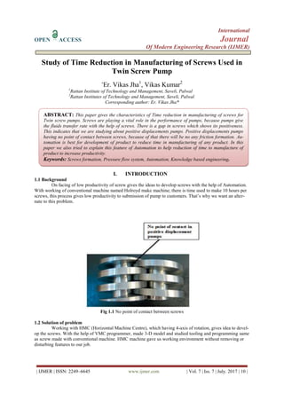
- 1. International OPEN ACCESS Journal Of Modern Engineering Research (IJMER) | IJMER | ISSN: 2249–6645 www.ijmer.com | Vol. 7 | Iss. 7 | July. 2017 | 10 | Study of Time Reduction in Manufacturing of Screws Used in Twin Screw Pump * Er. Vikas Jha1 , Vikas Kumar2 1 Rattan Institute of Technology and Management, Saveli, Palwal 2 Rattan Institutes of Technology and Management, Saveli, Palwal Corresponding author: Er. Vikas Jha* I. INTRODUCTION 1.1 Background On facing of low productivity of screw gives the ideas to develop screws with the help of Automation. With working of conventional machine named Holroyd make machine; there is time used to make 10 hours per screws, this process gives low productivity to submission of pump to customers. That’s why we want an alter- nate to this problem. Fig 1.1 No point of contact between screws 1.2 Solution of problem Working with HMC (Horizontal Machine Centre), which having 4-axis of rotation, gives idea to devel- op the screws. With the help of VMC programmer, made 3-D model and studied tooling and programming same as screw made with conventional machine. HMC machine gave us working environment without removing or disturbing features to our job. ABSTRACT: This paper gives the characteristics of Time reduction in manufacturing of screws for Twin screw pumps. Screws are playing a vital role in the performance of pumps, because pumps give the fluids transfer rate with the help of screws. There is a gap in screws which shows its positiveness. This indicates that we are studying about positive displacements pumps. Positive displacements pumps having no point of contact between screws, because of that there will be no any friction formation. Au- tomation is best for development of product to reduce time in manufacturing of any product. In this paper we also tried to explain this feature of Automation to help reduction of time to manufacture of product to increase productivity. Keywords: Screws formation, Pressure flow system, Automation, Knowledge based engineering.
- 2. Study of Time Reduction in Manufacturing of Screws Used in Twin Screw Pump | IJMER | ISSN: 2249–6645 www.ijmer.com | Vol. 7 | Iss. 7 | July. 2017 | 11 | 1.3 Process followed Steps to manufacture a screw from raw material to final product are as follows: - Rod cutting: Rod of SS 431 is used as raw material to develop the blank size of screw. Blank formation: Process of turning and facing done on CNC machine. Screw formation: programming and setting done on HMC machine. Cutting fluid is used to protect heat up the component. 1.4 Working Principle The operating principle of twin screw pumps Inside the pump housing rotates the pair of rotors, push- ing fluid located around the screw respectively screws step size. Liquid is supplied very uniformly and without pulsations and along the axis (not circumferentially as in centrifugal pumps). The liquids sensitive to mixing in cross section or turbulent mixing, subject to a small load during pumping:due to the absence of pulsations, low speed, the minimum number of centrifugal rotation and lack of contact be- tween the screws on the pumped product is not subject to changes in volume, texture, characteristics and properties. Due to the low inertia of the rotary parts, screw pumps can operate at higher speeds than other posi- tive displacement pumps, or equivalent volumetric chamber. 1.5 Parameters for Selecting of pump In order to select the most suitable pump for your application, you must consider a number of key pa- rameters. First and foremost, you must determine the type of installation of the pump and the manner in which the pump will be used in the system. In addition, it is important to take into account the feed rate of the pumped fluid flow (l / min or m³ / hr.); the total pressure feed rate of pressure (bar), and the index of the liquid column height below the pump suction pipe (NPSN). To the list of the key parameters to be considered when selecting a pump also relates nature of the pumped material (chemical composition, density, viscosity, pH, temperature), and the level contained suspended solids and degree of abrasiveness. Moreover, one should consider the level of the supply voltage and line frequency for connecting the motor and the type of the transmission mechanism be- tween the motor and the pump. 1.6Performance under different conditions such as Flow rate Viscosity Power consumption 1.6.1 Flow Rate 1. Chamber Size + number of screw 2. Speed 3. Differential Pressure 4. Viscosity 5. Gap design (screws, liner/casing) Flow rate =Volumetric Flow – Backflow Q total = Q volumetric – Q backflow 1.6.2 Viscosity 1. Chamber Size + number of screw 2. Speed 3. Differential Pressure 4. Viscosity, 5. Gas Content 6. Gap Design (screws, liner/casing) Less Backflow with higher fluid Viscosity Less Backflow with Gas. 1.6.3 Power Consumption 1. Speed 2. Differential Pressure 3. Viscosity Shaft Power = Hydraulic Power + Friction Pshaft = Phydraulic + Pfriction
- 3. Study of Time Reduction in Manufacturing of Screws Used in Twin Screw Pump | IJMER | ISSN: 2249–6645 www.ijmer.com | Vol. 7 | Iss. 7 | July. 2017 | 12 | Flow Rate is directly proportional to speed. Power Consumption depends on speed and differential pressure II. EXPERIMENTAL SET UP Pump casing Pump casing is a casing used to passes liquid through that which is made up of cast steel or cast iron of casing made. Suction as Inlet port used to give inside liquid pressure in pump and discharge as outlet port used to give outside pressure to transfer liquid through that casing. There are also two ports used in pump casing for shaft intake and outtake. Valve Casing Assembly Valve casing assembly is used to store fluid which come high pressure; there is relief valve through that valve casing can bear extra force of fluid. Gear casing Gear casing is used to cover the gears, gear used on the shaft to help transmit energy to move shaft as- sembly. Gear casing is used on both ends as drive and non-drive end of shaft. Bearing and Mechanical Seals Bearings are used to movement of shaft assembly, and Mechanical Seal is used to protect back pressure of liquid pressure from the pump casing. Pressure gauges Pressure gauges is used to measure the pressure of outgoing liquid, timing of transfer liquid is depend on the regulation control by the pressure gauge. Electrical Motor Motor is used to start the pump; electrical energy is converted into mechanical energy. Coupling Coupling is used between electrical motor and pump casing attached to drive end of shaft assembly. Base frame Base frame is uses as foundation of screw pump assembly. There is vibration damper also used. It is made of mild steel, channels and sheets. Foundation bolts & vibration damper Foundation bolts are used to fix the base frame; base frame is stand on vibration damper to fix the vi- bration on running condition of pumps. 2.2 Block diagram III. RESULT OF EXPERIMENT Quality Assurance Report: Holroyd made screw sets data: Table: 3.1 Pump input data Viscosity (cst) Discharge pr. (bar) Speed (rpm) Capacity (m3/hr.) Power Absorbed (kw) 2 20 2.84 1450 100 1.119 2.87 Table: 3.2 On Process Test Result Qth Suction Pr. Diff. Pressure Speed For capacity For Power litre time amp volt PF without eff. Power
- 4. Study of Time Reduction in Manufacturing of Screws Used in Twin Screw Pump | IJMER | ISSN: 2249–6645 www.ijmer.com | Vol. 7 | Iss. 7 | July. 2017 | 13 | 131.40 0 0.00 1450 117 3.60 26.4 378 0.70 12.10 0 1.00 1450 110 3.60 31.4 378 0.72 14.80 0 2.00 1450 104 3.60 38.4 378 0.72 18.10 0 3.00 1449 98 3.60 45.0 378 0.74 21.74 0 4.00 1449 92 3.60 51.4 377 0.74 24.90 0 5.00 1449 87 3.60 59.1 376 0.76 29.40 0 6.00 1449 83 3.60 65.1 368 0.78 32.53 0 7.00 1449 78 3.60 79.5 368 0.81 40.79 0 8.00 1448 74 3.60 89.9 368 0.81 46.53 0 9.00 1448 71 3.60 100.0 369 0.83 53.95 0 10.00 1448 67 3.60 107.0 366 0.84 56.84 Table: 3.3 Result of input Data Test condition Diff. Pressure Speed capacity with viscosity curve data % water 35.0 C 1 cst 0.00 1450 117 117.53 126 92.86 1.00 1450 110 110.79 122.5 89.8 2.00 1450 104 105.01 119 87.39 3.00 1449 98 99.32 115 85.22 4.00 1449 92 93.54 112 82.14 5.00 1449 87 88.72 109 79.82 6.00 1449 83 84.87 107 77.57 7.00 1449 78 80.05 104 75 8.00 1448 74 76.29 102 72.55 9.00 1448 71 73.40 99 71.72 10.00 1448 67 69.54 98 68.37 Table: 3.4 Technical sheets Barometric Pressure A 9.96 Vapour Pressure of Liqiud at35 ̊C B 0.66 Suction Pressure C 9.30 Flow velocity corresponding to pipe size & Flow V 1.40 Velocity Head D= V2/2g where V=Q/a, a=(ᴨ/4 d2) 0.10 Suction Pressure Discharge Pressure (kg/cm2) Diff. Pressure (kg/cm2) Capacity (m3/Hr. NPSH mm Hg Bar mWc - 0.3 3 4.7 5 91 6.4 - 0.5 5 4.5 5 91 4.4 - 0.7 7 4.3 5 91 2.4 - 0.8 8 4.2 5 90 1.4 - 0.9 9 4.1 5 87 0.4 Hmcmade screw sets data: Table: 3.5 Pump input data Viscosity (cst) Discharge pr. (bar) Speed (rpm) Capacity (m3/hr.) Power Absorbed (kw) 2 20 2.84 1450 100 1.119 2.87 Table: 3.6 On Process Test Result Qth Suction Pr. Diff. Pres- sure Speed For capacity For Power litre time amp volt PF without eff. Power 131.40 0 0.00 1452 121 3.60 20.9 362 0.92 40 0 1.00 1451 116 3.60 29 362 0.74 40 0 2.00 1451 109 3.60 36 364 0.75 40 0 3.00 1451 102 3.60 43.2 363 0.78 40 0 4.00 1452 96 3.60 50 363 0.79 40 0 5.00 1451 90 3.60 58 362 0.8 50 0 6.00 1451 85 3.60 66.7 362 0.87 50 0 7.00 1450 81 3.60 71.1 361 0.82 60
- 5. Study of Time Reduction in Manufacturing of Screws Used in Twin Screw Pump | IJMER | ISSN: 2249–6645 www.ijmer.com | Vol. 7 | Iss. 7 | July. 2017 | 14 | 0 8.00 1450 77 3.60 78.9 359 0.83 65 0 9.00 1450 73 3.60 92.7 359 0.85 70 0 10.00 1449 70 3.60 108.0 358 0.87 80 Table: 3.8 Technical sheets Barometric Pressure A 9.96 Vapour Pressure of Liqiud at35 ̊C B 0.66 Suction Pressure C 9.30 Flow velocity corresponding to pipe size & Flow V 1.57 Velocity Head D= V2/2g where V=Q/a, a=(ᴨ/4 d2) 0.13 Suction Pressure Discharge Pres- sure (kg/cm2) Diff. Pressure (kg/cm2) Capacity (m3/Hr. NPSH mm Hg Bar mWc 0.3 3 2.5 2.8 100 6.43 0.5 5 2.3 2.8 101 4.43 0.7 7 2.1 2.8 101 2.43 0.8 8 2 2.8 99.5 1.43 0.9 9 1.9 2.8 96 0.43 IV. CONCLUSION By doing this type of Experiment we save: 1. 20 hours of manufacturing time, 2. 20 hours of Electricity Bills, 3. 20 hours of Machine maintenance cost. During this period we can fulfill other customer requirements. 5.1 Future scopes: To reduce manufacturing time by using alternate method of automation is in progress. 1. Single screw pumps; rotors can make 2. Triple screw pumps; middle and side screw is in progress 3. High pressure pumps parts such as connecting rods, plungers is in designing process for development. 2. APPENDIX Properties used Viscosity 1.002 mPa at 20°c water temperature Density 1000 kg/m3 Atmospheric pressure 14.66 psi Vapour pressure 38.7° c Velocity m3/sec Velocity Head meter Er. Vikas Jha. "Study of Time Reduction in Manufacturing of Screws Used in Twin Screw Pump." Inter- national Journal of Modern Engineering Research (IJMER) 7.7 (2017): 10-14