SlideShare uma empresa Scribd logo
1 de 7
Baixar para ler offline
International Journal of Innovative Research in Advanced Engineering (IJIRAE) ISSN: 2349-2163
Volume 1 Issue 5 (June 2014) http://ijirae.com
_________________________________________________________________________________________________
© 2014, IJIRAE- All Rights Reserved Page - 192
Experimental Analysis of Refrigeration system using
Microchannel condenser & Round Tube condenser
1
D.P.Patil 2
J.H.Bhangale 3
K.S.Deshmukh
1
PG Student, Mech Dept., MCERC Nasik 2
H.O.D.Mech Dept, MCERC Nasik 3
Mech.Department MCERC Nasik
ABSTRACT -Micro channel condenser now days can be effectively used due to its compact size in automobile sector. For
its performance, refrigeration set up designed to detect experimental performance of microchannel condenser. In this
paper performance analysis of microchannel condenser compared with round tube and coil tube. In analysis of
microchannel condensers it can be found more effective at various loads and operating conditions. For review same size of
microchannel and round tube condenser are considered. From the previous experiments the micro-channel condenser was
made to have nearly an identical face area, depth and fin density as the round-tube condenser which was the baseline. Also
varying the refrigerants, C.O.P & Efficiency of micro channel the various reviews of reviewer micro channel condenser
can be efficient and also refrigerator system requires less power.
Key words: Microchannel condenser, Round tube condenser, COP, Efficiency, refrigeration.
I.INTRODUCTION
The purpose of this review is to experimentally estimate improved condenser and evaporator capacity and system COP by
replacing a round-tube condenser with a micro channel condenser having almost identical frontal area and depth, without
considering heat exchanger cost. The baseline (round tube) condenser along with all other elements of the system was part of
a carefully sized air-conditioning system.With the advent of refrigeration, interest in condensation has increased since a
condenser is one of the main components of the basic vapor-compression refrigeration. Fig.(1) shows a schematic of a full
microchannelcondenser. The tubes are brazed to the headers with louvered fins in between. The refrigerant is circuited using
baffles inside the headers, involving more than one tube in each pass. This reduces the total pressure drop of the condenser
due to fewer passes.These heat exchangers provide the same amount of heat transfer with a much lower refrigerant charge
(about 2/3 that of a serpentine condenser) than condensers now commonly used in the industry. This attribute is very
beneficial to car manufacturers as any reduction in the space.Also, a smaller charge requirement translates into a lower cost
for installation and less of a threat to the environment should the system ever leak.
.
Fig.1. Microchannel condenser
Now, a days while considering the global environment it is necessary to overcome ozone depletion, greenhouse effect, and
other problems associated with the current state of technology, research in refrigeration has grown even more. Now, research
focuses on determining the properties and effects of using alternative, non chlorofluorocarbon (CFC) refrigerants such as 1,
1,1,2-tetrafluoroethane (R-134a) as replacements for the commonly used CFC's. Time is being wisely spent on new
refrigeration component technology in order to protect our finite environment. This project will follow suit by using ozone-
safe R-134a and R-190a as its working fluid. The future use of the microchannel condenser technology is predicted to increase
substantially over the next decade. The new government rules relate to refrigeration system can be easily followed if micro
channel condenser with R134a and R190a can be used as a refrigerant.
I.EXPERIMENTAL SETUP
International Journal of Innovative Research in Advanced Engineering (IJIRAE) ISSN: 2349-2163
Volume 1 Issue 5 (June 2014) http://ijirae.com
_________________________________________________________________________________________________
© 2014, IJIRAE- All Rights Reserved Page - 193
In this project three types of condenser are used
1.micro channel condenser
2.Round tube condenser
3.Coil- tube condenser
In this experiment using refrigerant R134a,cop of refrigerant is calculated . Compressor passes refrigerant to two condenser
one after another cop of both the system is thus calculated.
Fig 2. Schematic experimental setup
Fig 3.Actual setup
Fig 4.Actual setup
International Journal of Innovative Research in Advanced Engineering (IJIRAE) ISSN: 2349-2163
Volume 1 Issue 5 (June 2014) http://ijirae.com
_________________________________________________________________________________________________
© 2014, IJIRAE- All Rights Reserved Page - 194
III.PROCEDURE
1. Connect the two plugs to main.
2. Before ON the supply, conform that all the switches on panel are off position.
3. See the dimmerstat is at zero position.
4. Then put ON the heater switch & give power to heater.
5. This will heat the water in evaporator & this can be seen dial thermometer.
6. Adjust the heater voltage such that the Temperature dial thermometer reading reaches 25 - 300 C.Now ON the D.P.
switches.
7. Put ON the condenser fan switch & wait for 2 - 3 minutes.
8. Now switch ON the solenoid valve switch & the compressor switch.
9. The refrigeration flow will start. This can be confirmed on the sight glass.
10. Now the ammeter, voltmeter will show the current & voltage for compressor.
11. Note down the time for 10 revolutions of energy for compression. After some time
we will see that the Temperature of water in the evaporator slowly goes down & reaches steady state.( Adjust this temp. at 28
to 300 C).
Basic paremeters –
1. HP Condenser pressure in Kg/cm2. = Kg/cm2
2. LP Evaporator Pressure in Kg/Cm2 = Kg/cm2
3. Rotameter in Reading LPH = LPH
4. Condenser Inlet Temperature in 0C = T1
5. Condenser Outlet Temperature 0C = T
6. Evaporator Inlet Temperature in 0C = Tci
7. Evaporator Outlet Temperature 0C = Teo
8. Time for 10 Pulses of heater energymeter = in sec
9. Time for 10 Pulses of comp energymeter = in sec.
10. Ammeter reading = in Amp
11. Voltmeter reading = in V
12. Evaporator Bath Temp in 0C = 0C
IV.SPECIFICATIONS
1. COMPRESSOR : Hermetically sealed type
Kirloskar Make 1/3 T. Capacity.
2. AIR COOLED CONDENSOR : Copper Coils with fins & cooling fan.
3. EXPANSION DEVICE : i) Thermostatic expansion valve.
ii) Capillary Tube
4. EVAPORATOR : Copper Coil immersed in water. The evaporator is installed from outside to prevent heat loss.
5. ENERGY METER : One each for power supply to the Measurement of Compressor & Evaporator Heater.
6. DIMMERSTAT : To control power supply to heater.
7. PRESSURE GAUGE : One each for the measurement of high & low pressure.
8. ELECTRIC HEATER : Immersion type 1.5 Kw
9. DIGITAL TEMPERATURE INDICATOR : To Measure the temperatures at various Points i. e. Evaporator Inlet & Outlet
Condenser Inlet & Outlet temperatures of Refrigerant & Evaporator bath Temperature.
10. SOLINOID VALVE : Castle, Italy, Mate.
11. HP & LP CUTOUT : Safety device suitable for the low & high pressure of compressor.
12. SERVICE VALVE : Needle type for changing gas.
13. AMMETER : 0 - 15 Amps for compressor
14. VOLTMETER : 230 V, A.C. for compressor
15. FILTER DRYER : 1 No.
16. THERMOSTAT : Safety Device.
17. SWITCHES : For various controls
The refrigerant circuit is mounted on a board. The unit is supported on frame. Do not operate the changing valve.
See the sufficient water is filled in the evaporator container.
V.OBSERVATIONS
1. Compressor Energymeter Constant (E M C) com = 3200 Pulses/kWatt hr
2. Heater Energymeter Constant ( E M C) h = 3200 Pulses/kwatt hr
HP : Condenser Pressure in PSI
LP : Evaporator Pressure in PSI
Q : Refrigerant flow Rate in LPH
International Journal of Innovative Research in Advanced Engineering (IJIRAE) ISSN: 2349-2163
Volume 1 Issue 5 (June 2014) http://ijirae.com
_________________________________________________________________________________________________
© 2014, IJIRAE- All Rights Reserved Page - 195
T1 : Refrigerant inlet Temp. To Condenser in 0C
T2 : Refrigerant Outlet Temp. from microchannel condenser in 0C
T3:; Refrigerant outlet from round tube condenser
T4 : Refrigerant outlet from coil-tube condenser
T5 : Inlet temperature to evaporator
T6 : Outlet from evaporator
T7 : Inlet temperature of ice plant
T8 : Outlet temperature of ice plant
T9 : Bath temperature evaporator1
T10: Atmospheric temperature
T11: Air outlet temperature of michrochannel condenser
T12: Outlet tc : Time for 10 Pulses of Compressor energy meter in sec.
OBSERVATION TABLE
Sr.
No.
Temperature Microchannel
condenser
Round tube
condenser
Coil tune
condenser
I II III I II III I II III
1 T1 56.90 60 61.1 33.9 35.6 36.7 33.7 34.9 35.9
2 T2 32.9 33 33.81 32.83 33.9 34.2 32.8 33.5 34.6
3 T3 33.7 32.7 32.8 32.6 34.4 34.4 32.8 35.1 34.2
4 T4 33.2 33.4 32.7 31.5 37.9 31.8 32.01 36.8 32.2
5 T5 -5 -4.9 -1.8 12.21 15.2 18.6 11.8 14.8 18.3
6 T6 - - - - - - - - -
7 T7 33.4 33.6 34.2 31.8 32.2 32.7 32.1 33.1 31.2
8 T8 31.8 31.9 32.4 29.8 30.5 31.1 30.1 30.7 31.3
9 T9 28.2 22.7 20.2 16.5 14.1 12 19.6 17 13
10 T10 - - - - - - - - -
11 T11 33.2 33.6 34.1 33.4 34.2 34.6 33.2 34.1 34.8
12 T12 30.9 31.2 31.2 32.5 32.8 33.4 31.6 32.2 32.9
Microchannel condenser-
Sr.No, Evaporator Compressor
Heater Input Temperature Difference
After 15 min.
Time required for 10 number of pulse
V(Volt) I(Amp) T9i
(°C)
T9f
(°C)
1 230 0.901 28.2 24.6 124.47
2 231 0.869 22.7 20.4 190.8
3 215 0.823 20.2 18.4 232
4 229 0.965 31.1 28.7 187
5 230 0.984 30.0 27.4 128
Round tube condenser-
Sr.No, Evaporator Compressor
Heater Input Temperature Difference
After 15 min.
Time required for 10 number of pulse
V(Volt) I(Amp) T9i
(°C)
T9f
(°C)
1 229 0.965 16.5 14.2 138
2 230 0.984 14.1 12.2 155
3 226 0.938 12.0 9.3 97
4 225 0.935 20.2 18.1 159
5 223 0.965 18.1 16.8 257
Coil tube condenser –
Sr.No, Evaporator Compressor
Heater Input Temperature Difference
After 15 min.
Time required for 10 number of pulse
V(Volt) I(Amp) T9i
(°C)
T9f
(°C)
International Journal of Innovative Research in Advanced Engineering (IJIRAE) ISSN: 2349-2163
Volume 1 Issue 5 (June 2014) http://ijirae.com
_________________________________________________________________________________________________
© 2014, IJIRAE- All Rights Reserved Page - 196
1 221 0.920 19.6 17.3 138
2 223 1.001 17 14.1 97
3 224 0.818 13 10.6 143
4 229 0.965 22.3 20.1 130
5 230 0.984 20 18.3 187
VI.CALCULATION
Temperature of bath T9 = 19.4
V = 216volt
I = 0.793amp
Time for 10 pulses (tc) = 2.39 min
= 143.4 sec
Compressor power –
= Nc*3600
Tc*3200
= 10*3600
124.47*3200
=90.38 watt
RE = mCp ΔT = 7*4186*(28.2-24.6)
Time 15*60
= 117.208 watt
COP= RE
Compressor power
= 117.208
90.38
Cop=1.298
Carnot COP
i) Suction LP=31PSI=(31*0.0731)+1.013
SuctionLP=3.279kg per cm2
TL=2 °C
TL=275K
ii) Delivery HP=141PSI =(141*0.0731)+1.013
=10.927 kg per sq.cm
TH= 45 °C
TH=318K
Carnot COP= = TL
TH – TL
= 275
318- 275
= 6.39
Efficiency = Actual COP = 1.298 *100
Carnot COP 6.39
= 20.31 %
VII.RESULT TABLE
Microchannel condenser –
Sr. no. Evaporator Compressor Coefficient of
Performance
Carnot COP Efficiency
Heat supplied to Evaporator Compressor
Work
Qevap (RE)
Load
Wc COP
1 117.208 90.38 1.298 6.39 20.31
2 74.88 59.2 1.27 6.41 19.81
3 58.60 48.49 1.208 6.50 18.58
4 78.13 60.1 1.3 6.35 20.47
5 84.60 87.21 0.97 6.43 15.08
International Journal of Innovative Research in Advanced Engineering (IJIRAE) ISSN: 2349-2163
Volume 1 Issue 5 (June 2014) http://ijirae.com
_________________________________________________________________________________________________
© 2014, IJIRAE- All Rights Reserved Page - 197
Round tube condenser-
Sr. no. Evaporator Compressor Coefficient of
Performance
Carnot COP Efficiency
Heat supplied to Evaporator Compressor
Work
Qevap (RE)
Load
Wc COP
1 74.88 81.5 0.92 6.571 14.15
2 58.604 72.58 0.81 6.0 13.5
3 84.906 115.97 0.76 6.39 11.89
4 68.37 70.48 0.95 6.01 15.80
5 42.32 43.62 0.97 5.70 17.01
Coil-tube condenser –
Sr. no. Evaporator Compressor Coefficient of
Performance
Carnot COP Efficiency
Heat supplied to Evaporator Compressor
Work
Qevap (RE)
Load
Wc COP
1 74.88 81.52 0.92 6.5 14.15
2 94.41 115.97 0.814 6 13.5
3 68.37 78.67 0.869 6.39 11.89
4 71.62 86.28 0.83 6.3 13.17
5 55.34 60.15 0.92 5.8 45.86
VIII. Graph
Efficiency: Micro channel Condenser-
Roundtube Condenser-
17.5
18
18.5
19
19.5
20
20.5
21
efficiency
Mirochannel Condenser
Mirochannel
efficiency
Load
0
5
10
15
20
74.88 58.604 87.906 68.37 42.32
efficiency
Roundtube Condenser
Roundtube
efficiency
Load
International Journal of Innovative Research in Advanced Engineering (IJIRAE) ISSN: 2349-2163
Volume 1 Issue 5 (June 2014) http://ijirae.com
_________________________________________________________________________________________________
© 2014, IJIRAE- All Rights Reserved Page - 198
Coil tube condenser-
IX.CONCLUSION
In this study, air-conditioning systems with a micro-channel condenser and a round-tube condenser and coil tube were
experimentally examined. These three condensers hadalmost identical frontal area and depth because the purpose of this study
was to measure performance improvement using the micro-channel condenser which had an almost identical package volume
as the round-tube condenser. An economic issue such as heat exchanger cost was not considered. Significant performance
improvement was presented for the system with the micro-channel condenser. The COP of the system with the microchannel
condenser is around 7-8% higher than that with the round condenser in ARI A condition. Also, using a micro-channel
condenser resulted in a 2.5 ᵒC lower condensing temperature and decreased the refrigerant pressure drop from 166 kPa in the
round-tube condenser to 57 kPa in the micro-channel condenser. The refrigerant charge amount for the system with the micro-
channel condenser was 9.2% smaller than that with the roundtube condenser. Even though the micro-channel condenser
showed better heat transfer performance of capacity and system COP than the round-tube condenser, the round tube condenser
has a cost advantage at this point in time. The micro-channel condenser was also investigated using a numerical model. The
model could estimate the condenser capacity accurately. From the simulation results, it could be calculated that the
consideration of non-uniform distribution for the air and refrigerant did not make a significant difference for predicting the
condenser capacity. However, this small influence of non-uniform air and refrigerant on capacity is valid only for the
microchannel condenser examined in this study. The air and refrigerant mal-distribution effect on heat exchanger capacity is
different according to the types of heat exchanger (microchannel or round tube), the usage of heat exchanger (evaporators or
condensers), and the circuit geometry of heat exchangers.
X.REFERENCES
[1] ANSI/ASHRAE Standard 37-2005, 2005. Method of Testing for Rating Electrically Driven Unitary Air- Conditioning and Heat Pump
Equipment. American Society of Heating, Refrigerating and Air-Conditioning Engineers, Inc., Atlanta, GA, USA.
[2] ARI Standard 210/240, 2003. Standard for Unitary Air Conditioning and Air Source Heat Pump Equipment. Air Conditioning and
Refrigeration Institute, Arlington, VA, USA.
[3]. Aganda, A.A., Coney, J.E.R., Sheppard, C.G.W., 2000. Airflow maldistribution and the performance of a packaged air conditioning
unit evaporator. Appl. Therm. Eng. 20, 515–528.
[4]. Beaver, A.C., Yin, J.M., Bullard, C.W., Hrnjak, P.S., 1999. An experimental Investigation of Transcritical Carbon dioxide Systems for
Residential Air-Conditioning.
[5]. ACRC Report CR-18.University of Illinois at Urbana-Champaign, Urbana, IL, USA.
[6]. Brix, W., Jakobsen, A. Rasmussen, B.D., Carlsen, H., 2007.Analysis of air flow distribution in refrigeration system. In:International
Congress of Refrigeration, ICR07-B2-581, Beijing.
[7]. Chang, Y.J., Wang, C.C., 1997. A generalized heat transfer correlation for louver fin geometry. Int. J. Heat Mass Transfer 40, 533–544.
[8]. Choi, J.M., Payne, W.V., Domanski, P.A., 2003. Effects of non-uniform refrigerant and air flow distributions on finned-tube
evaporator performance. In:International Congress of Refrigeration, ICR0040, Washington DC.
[9]. Domanski, P.A., 1991. Simulation of an evaporator with non-uniform onedimensional air distribution. ASHRAE Trans.97, 793–802.
[10]. Elbel, S., Hrnjak, P.S., 2004. Flash gas bypass for improving the performance of transcritical R744 systems that useMicro-channel
evaporators. Int. J. Refrigeration 27, 724–735.
[11]. Friedel, L., 1979. Improved friction pressure correlation for horizontal and vertical two-phase pipe flow. In: The EuropeanTwo-Phase
Flow Group Meeting, paper E2, Ispra, Italy.
[12]. Fagan, T.J., 1980. The effects of air flow maldistributions on air to refrigerant heat exchanger performance. ASHRAE Trans.86, 699–
713.
[13]. Hrnjak, P.S., 2002. Micro-channel Heat Exchangers as a Design Option for Charge Reduction in NH3 and HC Systems. Zero
Leakage-Minimum Charge. IIR/IIF, Stockholm, p. 91. Incropera, F.P., DeWitt, D.P., 2002.
[14]. Fundamentals of Heat and Mass Transfer, fifth ed. John Wiley & Sons, New York.
[15]. Kandlikar, S.G., 2002. Fundamental issues related to flow boiling in minichannel sand microchannels. Exp. Therm. Fluid Sci. 26,389–
407.
[16]. Klein, S.A., 2005. Engineering Equation Solver. Academic professional V7.457- 3D. F-Chart Software,Madison, WI, USA.
0
5
10
15
20
74.88 94.41 68.37 71.62 55.34
efficiency
Coil tube Condenser
Coil tube
efficiency

Mais conteúdo relacionado

Mais procurados

Basic steam engineering nucleate boiling ppt
Basic steam engineering nucleate boiling pptBasic steam engineering nucleate boiling ppt
Basic steam engineering nucleate boiling pptFARRUKH SHEHZAD
 
Kt Mrs D Problems 1a
Kt Mrs D Problems 1aKt Mrs D Problems 1a
Kt Mrs D Problems 1adodinhkhai
 
Throttling calorimeter
Throttling calorimeterThrottling calorimeter
Throttling calorimeterKishan Trivedi
 
Refrigeration and Air Conditioning
Refrigeration and Air ConditioningRefrigeration and Air Conditioning
Refrigeration and Air Conditioningdineshucer
 
DESIGN OF AIR PRE HEATER AND ECONOMIZER
DESIGN OF AIR PRE HEATER AND ECONOMIZERDESIGN OF AIR PRE HEATER AND ECONOMIZER
DESIGN OF AIR PRE HEATER AND ECONOMIZERGopi Chand
 
Evaporator performance
Evaporator performanceEvaporator performance
Evaporator performanceMamta Sahurkar
 
Cascade Refrigeration System 2016
Cascade Refrigeration System 2016Cascade Refrigeration System 2016
Cascade Refrigeration System 2016Srikanta Biswas
 
4 cooling system dynamics
4 cooling system dynamics4 cooling system dynamics
4 cooling system dynamicsFuad Kareem.
 
Tons of Refrigeration
Tons of RefrigerationTons of Refrigeration
Tons of RefrigerationAshutosh
 
Refrigeration and air conditioning
Refrigeration and air conditioningRefrigeration and air conditioning
Refrigeration and air conditioningEagle .
 
Etht grp 16 (1400080125029,30,31,32)
Etht grp 16 (1400080125029,30,31,32)Etht grp 16 (1400080125029,30,31,32)
Etht grp 16 (1400080125029,30,31,32)Yash Dobariya
 

Mais procurados (20)

Heat transfer
Heat transferHeat transfer
Heat transfer
 
Basic steam engineering nucleate boiling ppt
Basic steam engineering nucleate boiling pptBasic steam engineering nucleate boiling ppt
Basic steam engineering nucleate boiling ppt
 
Kt Mrs D Problems 1a
Kt Mrs D Problems 1aKt Mrs D Problems 1a
Kt Mrs D Problems 1a
 
Throttling calorimeter
Throttling calorimeterThrottling calorimeter
Throttling calorimeter
 
PLATE FREEZER
PLATE FREEZERPLATE FREEZER
PLATE FREEZER
 
Throttling calorimeter
Throttling calorimeterThrottling calorimeter
Throttling calorimeter
 
Be 4120 project
Be 4120 projectBe 4120 project
Be 4120 project
 
Psychrometry
PsychrometryPsychrometry
Psychrometry
 
Hvac formulas
Hvac formulasHvac formulas
Hvac formulas
 
Refrigeration and Air Conditioning
Refrigeration and Air ConditioningRefrigeration and Air Conditioning
Refrigeration and Air Conditioning
 
DESIGN OF AIR PRE HEATER AND ECONOMIZER
DESIGN OF AIR PRE HEATER AND ECONOMIZERDESIGN OF AIR PRE HEATER AND ECONOMIZER
DESIGN OF AIR PRE HEATER AND ECONOMIZER
 
Steam Engineering basics
Steam Engineering basicsSteam Engineering basics
Steam Engineering basics
 
Air conditioning
Air conditioningAir conditioning
Air conditioning
 
Evaporator performance
Evaporator performanceEvaporator performance
Evaporator performance
 
Cascade Refrigeration System 2016
Cascade Refrigeration System 2016Cascade Refrigeration System 2016
Cascade Refrigeration System 2016
 
4 cooling system dynamics
4 cooling system dynamics4 cooling system dynamics
4 cooling system dynamics
 
Tons of Refrigeration
Tons of RefrigerationTons of Refrigeration
Tons of Refrigeration
 
Refrigeration and air conditioning
Refrigeration and air conditioningRefrigeration and air conditioning
Refrigeration and air conditioning
 
Etht grp 16 (1400080125029,30,31,32)
Etht grp 16 (1400080125029,30,31,32)Etht grp 16 (1400080125029,30,31,32)
Etht grp 16 (1400080125029,30,31,32)
 
Air conditioning
Air conditioningAir conditioning
Air conditioning
 

Semelhante a Experimental Analysis of Refrigeration system using Microchannel condenser & Round Tube condenser

ANALYSIS OF VAPOR COMPRESSION REFRIGERATION SYSTEM WITH DIFFERENT CONFIGURATI...
ANALYSIS OF VAPOR COMPRESSION REFRIGERATION SYSTEM WITH DIFFERENT CONFIGURATI...ANALYSIS OF VAPOR COMPRESSION REFRIGERATION SYSTEM WITH DIFFERENT CONFIGURATI...
ANALYSIS OF VAPOR COMPRESSION REFRIGERATION SYSTEM WITH DIFFERENT CONFIGURATI...ijiert bestjournal
 
INTEGRATION OF WATER CHILLER AND AIR COOLER
INTEGRATION OF WATER CHILLER AND AIR COOLERINTEGRATION OF WATER CHILLER AND AIR COOLER
INTEGRATION OF WATER CHILLER AND AIR COOLERIRJET Journal
 
Design Calculation of Main Components for Lab Based Refrigeration System
Design Calculation of Main Components for Lab Based Refrigeration SystemDesign Calculation of Main Components for Lab Based Refrigeration System
Design Calculation of Main Components for Lab Based Refrigeration Systemijtsrd
 
Design Calculation of Lab Based Vapour Compression System
Design Calculation of Lab Based Vapour Compression SystemDesign Calculation of Lab Based Vapour Compression System
Design Calculation of Lab Based Vapour Compression Systemijtsrd
 
Complete Evaluation of Vapour Compression Refrigeration System using R407C an...
Complete Evaluation of Vapour Compression Refrigeration System using R407C an...Complete Evaluation of Vapour Compression Refrigeration System using R407C an...
Complete Evaluation of Vapour Compression Refrigeration System using R407C an...IRJET Journal
 
IRJET-Multi Functional Compressor
IRJET-Multi Functional CompressorIRJET-Multi Functional Compressor
IRJET-Multi Functional CompressorIRJET Journal
 
Combined Air Refrigeration, Air Conditioning and Water Dispenser Systems
Combined Air Refrigeration, Air Conditioning and Water Dispenser SystemsCombined Air Refrigeration, Air Conditioning and Water Dispenser Systems
Combined Air Refrigeration, Air Conditioning and Water Dispenser SystemsIRJET Journal
 
Experimental investigate to obtain the effectiveness of regenerator using Air.
Experimental investigate to obtain the effectiveness of regenerator using Air.Experimental investigate to obtain the effectiveness of regenerator using Air.
Experimental investigate to obtain the effectiveness of regenerator using Air.IJESFT
 
Modification of Generator In Electrolux Refrigerator
Modification of Generator In Electrolux RefrigeratorModification of Generator In Electrolux Refrigerator
Modification of Generator In Electrolux RefrigeratorIRJET Journal
 
IRJET- Design and Fabrication of Simultaneous Heating and Cooling in VCR ...
IRJET-  	  Design and Fabrication of Simultaneous Heating and Cooling in VCR ...IRJET-  	  Design and Fabrication of Simultaneous Heating and Cooling in VCR ...
IRJET- Design and Fabrication of Simultaneous Heating and Cooling in VCR ...IRJET Journal
 
Experimental Optimization of Capillary Tube in Domestic Refrigerator
Experimental Optimization of Capillary Tube in Domestic RefrigeratorExperimental Optimization of Capillary Tube in Domestic Refrigerator
Experimental Optimization of Capillary Tube in Domestic Refrigeratorpaperpublications3
 
Multipurpose Device Using Single Vapor Compression Refrigeration Cycle
Multipurpose Device Using Single Vapor Compression Refrigeration CycleMultipurpose Device Using Single Vapor Compression Refrigeration Cycle
Multipurpose Device Using Single Vapor Compression Refrigeration CycleIRJET Journal
 
IRJET- Water Cooling With LPG as Refrigerant for Restaurants
IRJET- Water Cooling With LPG as Refrigerant for RestaurantsIRJET- Water Cooling With LPG as Refrigerant for Restaurants
IRJET- Water Cooling With LPG as Refrigerant for RestaurantsIRJET Journal
 
IRJET- Water Cooling With LPG as Refrigerant for Restaurants
IRJET- Water Cooling With LPG as Refrigerant for RestaurantsIRJET- Water Cooling With LPG as Refrigerant for Restaurants
IRJET- Water Cooling With LPG as Refrigerant for RestaurantsIRJET Journal
 
Improving Gas Turbine – HRSG output using Inlet Air Chilling and Converted Ev...
Improving Gas Turbine – HRSG output using Inlet Air Chilling and Converted Ev...Improving Gas Turbine – HRSG output using Inlet Air Chilling and Converted Ev...
Improving Gas Turbine – HRSG output using Inlet Air Chilling and Converted Ev...IRJET Journal
 
Review Paper on Performance Analysis of LPG Refrigerator
Review Paper on Performance Analysis of LPG RefrigeratorReview Paper on Performance Analysis of LPG Refrigerator
Review Paper on Performance Analysis of LPG RefrigeratorIRJET Journal
 
Comparative Study Between Cross Flow Air To Air Plate Fin Heat Exchanger With...
Comparative Study Between Cross Flow Air To Air Plate Fin Heat Exchanger With...Comparative Study Between Cross Flow Air To Air Plate Fin Heat Exchanger With...
Comparative Study Between Cross Flow Air To Air Plate Fin Heat Exchanger With...IRJET Journal
 
DOMESTIC REFRIGERATION USING LPG CYLINDER
DOMESTIC REFRIGERATION USING LPG CYLINDERDOMESTIC REFRIGERATION USING LPG CYLINDER
DOMESTIC REFRIGERATION USING LPG CYLINDERIRJET Journal
 
NUMERICAL ANALYSIS OF DOUBLE INLET PULSE TUBE REFRIGERATOR
NUMERICAL ANALYSIS OF DOUBLE INLET PULSE TUBE REFRIGERATORNUMERICAL ANALYSIS OF DOUBLE INLET PULSE TUBE REFRIGERATOR
NUMERICAL ANALYSIS OF DOUBLE INLET PULSE TUBE REFRIGERATORNetha Jashuva
 
Design and Analysis of Heat Exchanger for Maximum Heat Transfer Rate (Multi M...
Design and Analysis of Heat Exchanger for Maximum Heat Transfer Rate (Multi M...Design and Analysis of Heat Exchanger for Maximum Heat Transfer Rate (Multi M...
Design and Analysis of Heat Exchanger for Maximum Heat Transfer Rate (Multi M...IRJET Journal
 

Semelhante a Experimental Analysis of Refrigeration system using Microchannel condenser & Round Tube condenser (20)

ANALYSIS OF VAPOR COMPRESSION REFRIGERATION SYSTEM WITH DIFFERENT CONFIGURATI...
ANALYSIS OF VAPOR COMPRESSION REFRIGERATION SYSTEM WITH DIFFERENT CONFIGURATI...ANALYSIS OF VAPOR COMPRESSION REFRIGERATION SYSTEM WITH DIFFERENT CONFIGURATI...
ANALYSIS OF VAPOR COMPRESSION REFRIGERATION SYSTEM WITH DIFFERENT CONFIGURATI...
 
INTEGRATION OF WATER CHILLER AND AIR COOLER
INTEGRATION OF WATER CHILLER AND AIR COOLERINTEGRATION OF WATER CHILLER AND AIR COOLER
INTEGRATION OF WATER CHILLER AND AIR COOLER
 
Design Calculation of Main Components for Lab Based Refrigeration System
Design Calculation of Main Components for Lab Based Refrigeration SystemDesign Calculation of Main Components for Lab Based Refrigeration System
Design Calculation of Main Components for Lab Based Refrigeration System
 
Design Calculation of Lab Based Vapour Compression System
Design Calculation of Lab Based Vapour Compression SystemDesign Calculation of Lab Based Vapour Compression System
Design Calculation of Lab Based Vapour Compression System
 
Complete Evaluation of Vapour Compression Refrigeration System using R407C an...
Complete Evaluation of Vapour Compression Refrigeration System using R407C an...Complete Evaluation of Vapour Compression Refrigeration System using R407C an...
Complete Evaluation of Vapour Compression Refrigeration System using R407C an...
 
IRJET-Multi Functional Compressor
IRJET-Multi Functional CompressorIRJET-Multi Functional Compressor
IRJET-Multi Functional Compressor
 
Combined Air Refrigeration, Air Conditioning and Water Dispenser Systems
Combined Air Refrigeration, Air Conditioning and Water Dispenser SystemsCombined Air Refrigeration, Air Conditioning and Water Dispenser Systems
Combined Air Refrigeration, Air Conditioning and Water Dispenser Systems
 
Experimental investigate to obtain the effectiveness of regenerator using Air.
Experimental investigate to obtain the effectiveness of regenerator using Air.Experimental investigate to obtain the effectiveness of regenerator using Air.
Experimental investigate to obtain the effectiveness of regenerator using Air.
 
Modification of Generator In Electrolux Refrigerator
Modification of Generator In Electrolux RefrigeratorModification of Generator In Electrolux Refrigerator
Modification of Generator In Electrolux Refrigerator
 
IRJET- Design and Fabrication of Simultaneous Heating and Cooling in VCR ...
IRJET-  	  Design and Fabrication of Simultaneous Heating and Cooling in VCR ...IRJET-  	  Design and Fabrication of Simultaneous Heating and Cooling in VCR ...
IRJET- Design and Fabrication of Simultaneous Heating and Cooling in VCR ...
 
Experimental Optimization of Capillary Tube in Domestic Refrigerator
Experimental Optimization of Capillary Tube in Domestic RefrigeratorExperimental Optimization of Capillary Tube in Domestic Refrigerator
Experimental Optimization of Capillary Tube in Domestic Refrigerator
 
Multipurpose Device Using Single Vapor Compression Refrigeration Cycle
Multipurpose Device Using Single Vapor Compression Refrigeration CycleMultipurpose Device Using Single Vapor Compression Refrigeration Cycle
Multipurpose Device Using Single Vapor Compression Refrigeration Cycle
 
IRJET- Water Cooling With LPG as Refrigerant for Restaurants
IRJET- Water Cooling With LPG as Refrigerant for RestaurantsIRJET- Water Cooling With LPG as Refrigerant for Restaurants
IRJET- Water Cooling With LPG as Refrigerant for Restaurants
 
IRJET- Water Cooling With LPG as Refrigerant for Restaurants
IRJET- Water Cooling With LPG as Refrigerant for RestaurantsIRJET- Water Cooling With LPG as Refrigerant for Restaurants
IRJET- Water Cooling With LPG as Refrigerant for Restaurants
 
Improving Gas Turbine – HRSG output using Inlet Air Chilling and Converted Ev...
Improving Gas Turbine – HRSG output using Inlet Air Chilling and Converted Ev...Improving Gas Turbine – HRSG output using Inlet Air Chilling and Converted Ev...
Improving Gas Turbine – HRSG output using Inlet Air Chilling and Converted Ev...
 
Review Paper on Performance Analysis of LPG Refrigerator
Review Paper on Performance Analysis of LPG RefrigeratorReview Paper on Performance Analysis of LPG Refrigerator
Review Paper on Performance Analysis of LPG Refrigerator
 
Comparative Study Between Cross Flow Air To Air Plate Fin Heat Exchanger With...
Comparative Study Between Cross Flow Air To Air Plate Fin Heat Exchanger With...Comparative Study Between Cross Flow Air To Air Plate Fin Heat Exchanger With...
Comparative Study Between Cross Flow Air To Air Plate Fin Heat Exchanger With...
 
DOMESTIC REFRIGERATION USING LPG CYLINDER
DOMESTIC REFRIGERATION USING LPG CYLINDERDOMESTIC REFRIGERATION USING LPG CYLINDER
DOMESTIC REFRIGERATION USING LPG CYLINDER
 
NUMERICAL ANALYSIS OF DOUBLE INLET PULSE TUBE REFRIGERATOR
NUMERICAL ANALYSIS OF DOUBLE INLET PULSE TUBE REFRIGERATORNUMERICAL ANALYSIS OF DOUBLE INLET PULSE TUBE REFRIGERATOR
NUMERICAL ANALYSIS OF DOUBLE INLET PULSE TUBE REFRIGERATOR
 
Design and Analysis of Heat Exchanger for Maximum Heat Transfer Rate (Multi M...
Design and Analysis of Heat Exchanger for Maximum Heat Transfer Rate (Multi M...Design and Analysis of Heat Exchanger for Maximum Heat Transfer Rate (Multi M...
Design and Analysis of Heat Exchanger for Maximum Heat Transfer Rate (Multi M...
 

Mais de AM Publications

DEVELOPMENT OF TODDLER FAMILY CADRE TRAINING BASED ON ANDROID APPLICATIONS IN...
DEVELOPMENT OF TODDLER FAMILY CADRE TRAINING BASED ON ANDROID APPLICATIONS IN...DEVELOPMENT OF TODDLER FAMILY CADRE TRAINING BASED ON ANDROID APPLICATIONS IN...
DEVELOPMENT OF TODDLER FAMILY CADRE TRAINING BASED ON ANDROID APPLICATIONS IN...AM Publications
 
TESTING OF COMPOSITE ON DROP-WEIGHT IMPACT TESTING AND DAMAGE IDENTIFICATION ...
TESTING OF COMPOSITE ON DROP-WEIGHT IMPACT TESTING AND DAMAGE IDENTIFICATION ...TESTING OF COMPOSITE ON DROP-WEIGHT IMPACT TESTING AND DAMAGE IDENTIFICATION ...
TESTING OF COMPOSITE ON DROP-WEIGHT IMPACT TESTING AND DAMAGE IDENTIFICATION ...AM Publications
 
THE USE OF FRACTAL GEOMETRY IN TILING MOTIF DESIGN
THE USE OF FRACTAL GEOMETRY IN TILING MOTIF DESIGNTHE USE OF FRACTAL GEOMETRY IN TILING MOTIF DESIGN
THE USE OF FRACTAL GEOMETRY IN TILING MOTIF DESIGNAM Publications
 
TWO-DIMENSIONAL INVERSION FINITE ELEMENT MODELING OF MAGNETOTELLURIC DATA: CA...
TWO-DIMENSIONAL INVERSION FINITE ELEMENT MODELING OF MAGNETOTELLURIC DATA: CA...TWO-DIMENSIONAL INVERSION FINITE ELEMENT MODELING OF MAGNETOTELLURIC DATA: CA...
TWO-DIMENSIONAL INVERSION FINITE ELEMENT MODELING OF MAGNETOTELLURIC DATA: CA...AM Publications
 
USING THE GENETIC ALGORITHM TO OPTIMIZE LASER WELDING PARAMETERS FOR MARTENSI...
USING THE GENETIC ALGORITHM TO OPTIMIZE LASER WELDING PARAMETERS FOR MARTENSI...USING THE GENETIC ALGORITHM TO OPTIMIZE LASER WELDING PARAMETERS FOR MARTENSI...
USING THE GENETIC ALGORITHM TO OPTIMIZE LASER WELDING PARAMETERS FOR MARTENSI...AM Publications
 
ANALYSIS AND DESIGN E-MARKETPLACE FOR MICRO, SMALL AND MEDIUM ENTERPRISES
ANALYSIS AND DESIGN E-MARKETPLACE FOR MICRO, SMALL AND MEDIUM ENTERPRISESANALYSIS AND DESIGN E-MARKETPLACE FOR MICRO, SMALL AND MEDIUM ENTERPRISES
ANALYSIS AND DESIGN E-MARKETPLACE FOR MICRO, SMALL AND MEDIUM ENTERPRISESAM Publications
 
REMOTE SENSING AND GEOGRAPHIC INFORMATION SYSTEMS
REMOTE SENSING AND GEOGRAPHIC INFORMATION SYSTEMS REMOTE SENSING AND GEOGRAPHIC INFORMATION SYSTEMS
REMOTE SENSING AND GEOGRAPHIC INFORMATION SYSTEMS AM Publications
 
EVALUATE THE STRAIN ENERGY ERROR FOR THE LASER WELD BY THE H-REFINEMENT OF TH...
EVALUATE THE STRAIN ENERGY ERROR FOR THE LASER WELD BY THE H-REFINEMENT OF TH...EVALUATE THE STRAIN ENERGY ERROR FOR THE LASER WELD BY THE H-REFINEMENT OF TH...
EVALUATE THE STRAIN ENERGY ERROR FOR THE LASER WELD BY THE H-REFINEMENT OF TH...AM Publications
 
HMM APPLICATION IN ISOLATED WORD SPEECH RECOGNITION
HMM APPLICATION IN ISOLATED WORD SPEECH RECOGNITIONHMM APPLICATION IN ISOLATED WORD SPEECH RECOGNITION
HMM APPLICATION IN ISOLATED WORD SPEECH RECOGNITIONAM Publications
 
PEDESTRIAN DETECTION IN LOW RESOLUTION VIDEOS USING A MULTI-FRAME HOG-BASED D...
PEDESTRIAN DETECTION IN LOW RESOLUTION VIDEOS USING A MULTI-FRAME HOG-BASED D...PEDESTRIAN DETECTION IN LOW RESOLUTION VIDEOS USING A MULTI-FRAME HOG-BASED D...
PEDESTRIAN DETECTION IN LOW RESOLUTION VIDEOS USING A MULTI-FRAME HOG-BASED D...AM Publications
 
EFFECT OF SILICON - RUBBER (SR) SHEETS AS AN ALTERNATIVE FILTER ON HIGH AND L...
EFFECT OF SILICON - RUBBER (SR) SHEETS AS AN ALTERNATIVE FILTER ON HIGH AND L...EFFECT OF SILICON - RUBBER (SR) SHEETS AS AN ALTERNATIVE FILTER ON HIGH AND L...
EFFECT OF SILICON - RUBBER (SR) SHEETS AS AN ALTERNATIVE FILTER ON HIGH AND L...AM Publications
 
UTILIZATION OF IMMUNIZATION SERVICES AMONG CHILDREN UNDER FIVE YEARS OF AGE I...
UTILIZATION OF IMMUNIZATION SERVICES AMONG CHILDREN UNDER FIVE YEARS OF AGE I...UTILIZATION OF IMMUNIZATION SERVICES AMONG CHILDREN UNDER FIVE YEARS OF AGE I...
UTILIZATION OF IMMUNIZATION SERVICES AMONG CHILDREN UNDER FIVE YEARS OF AGE I...AM Publications
 
REPRESENTATION OF THE BLOCK DATA ENCRYPTION ALGORITHM IN AN ANALYTICAL FORM F...
REPRESENTATION OF THE BLOCK DATA ENCRYPTION ALGORITHM IN AN ANALYTICAL FORM F...REPRESENTATION OF THE BLOCK DATA ENCRYPTION ALGORITHM IN AN ANALYTICAL FORM F...
REPRESENTATION OF THE BLOCK DATA ENCRYPTION ALGORITHM IN AN ANALYTICAL FORM F...AM Publications
 
OPTICAL CHARACTER RECOGNITION USING RBFNN
OPTICAL CHARACTER RECOGNITION USING RBFNNOPTICAL CHARACTER RECOGNITION USING RBFNN
OPTICAL CHARACTER RECOGNITION USING RBFNNAM Publications
 
DETECTION OF MOVING OBJECT
DETECTION OF MOVING OBJECTDETECTION OF MOVING OBJECT
DETECTION OF MOVING OBJECTAM Publications
 
SIMULATION OF ATMOSPHERIC POLLUTANTS DISPERSION IN AN URBAN ENVIRONMENT
SIMULATION OF ATMOSPHERIC POLLUTANTS DISPERSION IN AN URBAN ENVIRONMENTSIMULATION OF ATMOSPHERIC POLLUTANTS DISPERSION IN AN URBAN ENVIRONMENT
SIMULATION OF ATMOSPHERIC POLLUTANTS DISPERSION IN AN URBAN ENVIRONMENTAM Publications
 
PREPARATION AND EVALUATION OF WOOL KERATIN BASED CHITOSAN NANOFIBERS FOR AIR ...
PREPARATION AND EVALUATION OF WOOL KERATIN BASED CHITOSAN NANOFIBERS FOR AIR ...PREPARATION AND EVALUATION OF WOOL KERATIN BASED CHITOSAN NANOFIBERS FOR AIR ...
PREPARATION AND EVALUATION OF WOOL KERATIN BASED CHITOSAN NANOFIBERS FOR AIR ...AM Publications
 
ANALYSIS ON LOAD BALANCING ALGORITHMS IMPLEMENTATION ON CLOUD COMPUTING ENVIR...
ANALYSIS ON LOAD BALANCING ALGORITHMS IMPLEMENTATION ON CLOUD COMPUTING ENVIR...ANALYSIS ON LOAD BALANCING ALGORITHMS IMPLEMENTATION ON CLOUD COMPUTING ENVIR...
ANALYSIS ON LOAD BALANCING ALGORITHMS IMPLEMENTATION ON CLOUD COMPUTING ENVIR...AM Publications
 
A MODEL BASED APPROACH FOR IMPLEMENTING WLAN SECURITY
A MODEL BASED APPROACH FOR IMPLEMENTING WLAN SECURITY A MODEL BASED APPROACH FOR IMPLEMENTING WLAN SECURITY
A MODEL BASED APPROACH FOR IMPLEMENTING WLAN SECURITY AM Publications
 

Mais de AM Publications (20)

DEVELOPMENT OF TODDLER FAMILY CADRE TRAINING BASED ON ANDROID APPLICATIONS IN...
DEVELOPMENT OF TODDLER FAMILY CADRE TRAINING BASED ON ANDROID APPLICATIONS IN...DEVELOPMENT OF TODDLER FAMILY CADRE TRAINING BASED ON ANDROID APPLICATIONS IN...
DEVELOPMENT OF TODDLER FAMILY CADRE TRAINING BASED ON ANDROID APPLICATIONS IN...
 
TESTING OF COMPOSITE ON DROP-WEIGHT IMPACT TESTING AND DAMAGE IDENTIFICATION ...
TESTING OF COMPOSITE ON DROP-WEIGHT IMPACT TESTING AND DAMAGE IDENTIFICATION ...TESTING OF COMPOSITE ON DROP-WEIGHT IMPACT TESTING AND DAMAGE IDENTIFICATION ...
TESTING OF COMPOSITE ON DROP-WEIGHT IMPACT TESTING AND DAMAGE IDENTIFICATION ...
 
THE USE OF FRACTAL GEOMETRY IN TILING MOTIF DESIGN
THE USE OF FRACTAL GEOMETRY IN TILING MOTIF DESIGNTHE USE OF FRACTAL GEOMETRY IN TILING MOTIF DESIGN
THE USE OF FRACTAL GEOMETRY IN TILING MOTIF DESIGN
 
TWO-DIMENSIONAL INVERSION FINITE ELEMENT MODELING OF MAGNETOTELLURIC DATA: CA...
TWO-DIMENSIONAL INVERSION FINITE ELEMENT MODELING OF MAGNETOTELLURIC DATA: CA...TWO-DIMENSIONAL INVERSION FINITE ELEMENT MODELING OF MAGNETOTELLURIC DATA: CA...
TWO-DIMENSIONAL INVERSION FINITE ELEMENT MODELING OF MAGNETOTELLURIC DATA: CA...
 
USING THE GENETIC ALGORITHM TO OPTIMIZE LASER WELDING PARAMETERS FOR MARTENSI...
USING THE GENETIC ALGORITHM TO OPTIMIZE LASER WELDING PARAMETERS FOR MARTENSI...USING THE GENETIC ALGORITHM TO OPTIMIZE LASER WELDING PARAMETERS FOR MARTENSI...
USING THE GENETIC ALGORITHM TO OPTIMIZE LASER WELDING PARAMETERS FOR MARTENSI...
 
ANALYSIS AND DESIGN E-MARKETPLACE FOR MICRO, SMALL AND MEDIUM ENTERPRISES
ANALYSIS AND DESIGN E-MARKETPLACE FOR MICRO, SMALL AND MEDIUM ENTERPRISESANALYSIS AND DESIGN E-MARKETPLACE FOR MICRO, SMALL AND MEDIUM ENTERPRISES
ANALYSIS AND DESIGN E-MARKETPLACE FOR MICRO, SMALL AND MEDIUM ENTERPRISES
 
REMOTE SENSING AND GEOGRAPHIC INFORMATION SYSTEMS
REMOTE SENSING AND GEOGRAPHIC INFORMATION SYSTEMS REMOTE SENSING AND GEOGRAPHIC INFORMATION SYSTEMS
REMOTE SENSING AND GEOGRAPHIC INFORMATION SYSTEMS
 
EVALUATE THE STRAIN ENERGY ERROR FOR THE LASER WELD BY THE H-REFINEMENT OF TH...
EVALUATE THE STRAIN ENERGY ERROR FOR THE LASER WELD BY THE H-REFINEMENT OF TH...EVALUATE THE STRAIN ENERGY ERROR FOR THE LASER WELD BY THE H-REFINEMENT OF TH...
EVALUATE THE STRAIN ENERGY ERROR FOR THE LASER WELD BY THE H-REFINEMENT OF TH...
 
HMM APPLICATION IN ISOLATED WORD SPEECH RECOGNITION
HMM APPLICATION IN ISOLATED WORD SPEECH RECOGNITIONHMM APPLICATION IN ISOLATED WORD SPEECH RECOGNITION
HMM APPLICATION IN ISOLATED WORD SPEECH RECOGNITION
 
PEDESTRIAN DETECTION IN LOW RESOLUTION VIDEOS USING A MULTI-FRAME HOG-BASED D...
PEDESTRIAN DETECTION IN LOW RESOLUTION VIDEOS USING A MULTI-FRAME HOG-BASED D...PEDESTRIAN DETECTION IN LOW RESOLUTION VIDEOS USING A MULTI-FRAME HOG-BASED D...
PEDESTRIAN DETECTION IN LOW RESOLUTION VIDEOS USING A MULTI-FRAME HOG-BASED D...
 
INTELLIGENT BLIND STICK
INTELLIGENT BLIND STICKINTELLIGENT BLIND STICK
INTELLIGENT BLIND STICK
 
EFFECT OF SILICON - RUBBER (SR) SHEETS AS AN ALTERNATIVE FILTER ON HIGH AND L...
EFFECT OF SILICON - RUBBER (SR) SHEETS AS AN ALTERNATIVE FILTER ON HIGH AND L...EFFECT OF SILICON - RUBBER (SR) SHEETS AS AN ALTERNATIVE FILTER ON HIGH AND L...
EFFECT OF SILICON - RUBBER (SR) SHEETS AS AN ALTERNATIVE FILTER ON HIGH AND L...
 
UTILIZATION OF IMMUNIZATION SERVICES AMONG CHILDREN UNDER FIVE YEARS OF AGE I...
UTILIZATION OF IMMUNIZATION SERVICES AMONG CHILDREN UNDER FIVE YEARS OF AGE I...UTILIZATION OF IMMUNIZATION SERVICES AMONG CHILDREN UNDER FIVE YEARS OF AGE I...
UTILIZATION OF IMMUNIZATION SERVICES AMONG CHILDREN UNDER FIVE YEARS OF AGE I...
 
REPRESENTATION OF THE BLOCK DATA ENCRYPTION ALGORITHM IN AN ANALYTICAL FORM F...
REPRESENTATION OF THE BLOCK DATA ENCRYPTION ALGORITHM IN AN ANALYTICAL FORM F...REPRESENTATION OF THE BLOCK DATA ENCRYPTION ALGORITHM IN AN ANALYTICAL FORM F...
REPRESENTATION OF THE BLOCK DATA ENCRYPTION ALGORITHM IN AN ANALYTICAL FORM F...
 
OPTICAL CHARACTER RECOGNITION USING RBFNN
OPTICAL CHARACTER RECOGNITION USING RBFNNOPTICAL CHARACTER RECOGNITION USING RBFNN
OPTICAL CHARACTER RECOGNITION USING RBFNN
 
DETECTION OF MOVING OBJECT
DETECTION OF MOVING OBJECTDETECTION OF MOVING OBJECT
DETECTION OF MOVING OBJECT
 
SIMULATION OF ATMOSPHERIC POLLUTANTS DISPERSION IN AN URBAN ENVIRONMENT
SIMULATION OF ATMOSPHERIC POLLUTANTS DISPERSION IN AN URBAN ENVIRONMENTSIMULATION OF ATMOSPHERIC POLLUTANTS DISPERSION IN AN URBAN ENVIRONMENT
SIMULATION OF ATMOSPHERIC POLLUTANTS DISPERSION IN AN URBAN ENVIRONMENT
 
PREPARATION AND EVALUATION OF WOOL KERATIN BASED CHITOSAN NANOFIBERS FOR AIR ...
PREPARATION AND EVALUATION OF WOOL KERATIN BASED CHITOSAN NANOFIBERS FOR AIR ...PREPARATION AND EVALUATION OF WOOL KERATIN BASED CHITOSAN NANOFIBERS FOR AIR ...
PREPARATION AND EVALUATION OF WOOL KERATIN BASED CHITOSAN NANOFIBERS FOR AIR ...
 
ANALYSIS ON LOAD BALANCING ALGORITHMS IMPLEMENTATION ON CLOUD COMPUTING ENVIR...
ANALYSIS ON LOAD BALANCING ALGORITHMS IMPLEMENTATION ON CLOUD COMPUTING ENVIR...ANALYSIS ON LOAD BALANCING ALGORITHMS IMPLEMENTATION ON CLOUD COMPUTING ENVIR...
ANALYSIS ON LOAD BALANCING ALGORITHMS IMPLEMENTATION ON CLOUD COMPUTING ENVIR...
 
A MODEL BASED APPROACH FOR IMPLEMENTING WLAN SECURITY
A MODEL BASED APPROACH FOR IMPLEMENTING WLAN SECURITY A MODEL BASED APPROACH FOR IMPLEMENTING WLAN SECURITY
A MODEL BASED APPROACH FOR IMPLEMENTING WLAN SECURITY
 

Último

Online electricity billing project report..pdf
Online electricity billing project report..pdfOnline electricity billing project report..pdf
Online electricity billing project report..pdfKamal Acharya
 
Double Revolving field theory-how the rotor develops torque
Double Revolving field theory-how the rotor develops torqueDouble Revolving field theory-how the rotor develops torque
Double Revolving field theory-how the rotor develops torqueBhangaleSonal
 
Bridge Jacking Design Sample Calculation.pptx
Bridge Jacking Design Sample Calculation.pptxBridge Jacking Design Sample Calculation.pptx
Bridge Jacking Design Sample Calculation.pptxnuruddin69
 
Navigating Complexity: The Role of Trusted Partners and VIAS3D in Dassault Sy...
Navigating Complexity: The Role of Trusted Partners and VIAS3D in Dassault Sy...Navigating Complexity: The Role of Trusted Partners and VIAS3D in Dassault Sy...
Navigating Complexity: The Role of Trusted Partners and VIAS3D in Dassault Sy...Arindam Chakraborty, Ph.D., P.E. (CA, TX)
 
Employee leave management system project.
Employee leave management system project.Employee leave management system project.
Employee leave management system project.Kamal Acharya
 
Online food ordering system project report.pdf
Online food ordering system project report.pdfOnline food ordering system project report.pdf
Online food ordering system project report.pdfKamal Acharya
 
COST-EFFETIVE and Energy Efficient BUILDINGS ptx
COST-EFFETIVE  and Energy Efficient BUILDINGS ptxCOST-EFFETIVE  and Energy Efficient BUILDINGS ptx
COST-EFFETIVE and Energy Efficient BUILDINGS ptxJIT KUMAR GUPTA
 
AIRCANVAS[1].pdf mini project for btech students
AIRCANVAS[1].pdf mini project for btech studentsAIRCANVAS[1].pdf mini project for btech students
AIRCANVAS[1].pdf mini project for btech studentsvanyagupta248
 
"Lesotho Leaps Forward: A Chronicle of Transformative Developments"
"Lesotho Leaps Forward: A Chronicle of Transformative Developments""Lesotho Leaps Forward: A Chronicle of Transformative Developments"
"Lesotho Leaps Forward: A Chronicle of Transformative Developments"mphochane1998
 
Computer Networks Basics of Network Devices
Computer Networks  Basics of Network DevicesComputer Networks  Basics of Network Devices
Computer Networks Basics of Network DevicesChandrakantDivate1
 
Thermal Engineering-R & A / C - unit - V
Thermal Engineering-R & A / C - unit - VThermal Engineering-R & A / C - unit - V
Thermal Engineering-R & A / C - unit - VDineshKumar4165
 
Work-Permit-Receiver-in-Saudi-Aramco.pptx
Work-Permit-Receiver-in-Saudi-Aramco.pptxWork-Permit-Receiver-in-Saudi-Aramco.pptx
Work-Permit-Receiver-in-Saudi-Aramco.pptxJuliansyahHarahap1
 
HAND TOOLS USED AT ELECTRONICS WORK PRESENTED BY KOUSTAV SARKAR
HAND TOOLS USED AT ELECTRONICS WORK PRESENTED BY KOUSTAV SARKARHAND TOOLS USED AT ELECTRONICS WORK PRESENTED BY KOUSTAV SARKAR
HAND TOOLS USED AT ELECTRONICS WORK PRESENTED BY KOUSTAV SARKARKOUSTAV SARKAR
 
Hazard Identification (HAZID) vs. Hazard and Operability (HAZOP): A Comparati...
Hazard Identification (HAZID) vs. Hazard and Operability (HAZOP): A Comparati...Hazard Identification (HAZID) vs. Hazard and Operability (HAZOP): A Comparati...
Hazard Identification (HAZID) vs. Hazard and Operability (HAZOP): A Comparati...soginsider
 
data_management_and _data_science_cheat_sheet.pdf
data_management_and _data_science_cheat_sheet.pdfdata_management_and _data_science_cheat_sheet.pdf
data_management_and _data_science_cheat_sheet.pdfJiananWang21
 
Bhubaneswar🌹Call Girls Bhubaneswar ❤Komal 9777949614 💟 Full Trusted CALL GIRL...
Bhubaneswar🌹Call Girls Bhubaneswar ❤Komal 9777949614 💟 Full Trusted CALL GIRL...Bhubaneswar🌹Call Girls Bhubaneswar ❤Komal 9777949614 💟 Full Trusted CALL GIRL...
Bhubaneswar🌹Call Girls Bhubaneswar ❤Komal 9777949614 💟 Full Trusted CALL GIRL...Call Girls Mumbai
 
Thermal Engineering -unit - III & IV.ppt
Thermal Engineering -unit - III & IV.pptThermal Engineering -unit - III & IV.ppt
Thermal Engineering -unit - III & IV.pptDineshKumar4165
 
Thermal Engineering Unit - I & II . ppt
Thermal Engineering  Unit - I & II . pptThermal Engineering  Unit - I & II . ppt
Thermal Engineering Unit - I & II . pptDineshKumar4165
 

Último (20)

Online electricity billing project report..pdf
Online electricity billing project report..pdfOnline electricity billing project report..pdf
Online electricity billing project report..pdf
 
Double Revolving field theory-how the rotor develops torque
Double Revolving field theory-how the rotor develops torqueDouble Revolving field theory-how the rotor develops torque
Double Revolving field theory-how the rotor develops torque
 
Bridge Jacking Design Sample Calculation.pptx
Bridge Jacking Design Sample Calculation.pptxBridge Jacking Design Sample Calculation.pptx
Bridge Jacking Design Sample Calculation.pptx
 
Navigating Complexity: The Role of Trusted Partners and VIAS3D in Dassault Sy...
Navigating Complexity: The Role of Trusted Partners and VIAS3D in Dassault Sy...Navigating Complexity: The Role of Trusted Partners and VIAS3D in Dassault Sy...
Navigating Complexity: The Role of Trusted Partners and VIAS3D in Dassault Sy...
 
Employee leave management system project.
Employee leave management system project.Employee leave management system project.
Employee leave management system project.
 
Online food ordering system project report.pdf
Online food ordering system project report.pdfOnline food ordering system project report.pdf
Online food ordering system project report.pdf
 
COST-EFFETIVE and Energy Efficient BUILDINGS ptx
COST-EFFETIVE  and Energy Efficient BUILDINGS ptxCOST-EFFETIVE  and Energy Efficient BUILDINGS ptx
COST-EFFETIVE and Energy Efficient BUILDINGS ptx
 
AIRCANVAS[1].pdf mini project for btech students
AIRCANVAS[1].pdf mini project for btech studentsAIRCANVAS[1].pdf mini project for btech students
AIRCANVAS[1].pdf mini project for btech students
 
"Lesotho Leaps Forward: A Chronicle of Transformative Developments"
"Lesotho Leaps Forward: A Chronicle of Transformative Developments""Lesotho Leaps Forward: A Chronicle of Transformative Developments"
"Lesotho Leaps Forward: A Chronicle of Transformative Developments"
 
Computer Networks Basics of Network Devices
Computer Networks  Basics of Network DevicesComputer Networks  Basics of Network Devices
Computer Networks Basics of Network Devices
 
Thermal Engineering-R & A / C - unit - V
Thermal Engineering-R & A / C - unit - VThermal Engineering-R & A / C - unit - V
Thermal Engineering-R & A / C - unit - V
 
Integrated Test Rig For HTFE-25 - Neometrix
Integrated Test Rig For HTFE-25 - NeometrixIntegrated Test Rig For HTFE-25 - Neometrix
Integrated Test Rig For HTFE-25 - Neometrix
 
Call Girls in South Ex (delhi) call me [🔝9953056974🔝] escort service 24X7
Call Girls in South Ex (delhi) call me [🔝9953056974🔝] escort service 24X7Call Girls in South Ex (delhi) call me [🔝9953056974🔝] escort service 24X7
Call Girls in South Ex (delhi) call me [🔝9953056974🔝] escort service 24X7
 
Work-Permit-Receiver-in-Saudi-Aramco.pptx
Work-Permit-Receiver-in-Saudi-Aramco.pptxWork-Permit-Receiver-in-Saudi-Aramco.pptx
Work-Permit-Receiver-in-Saudi-Aramco.pptx
 
HAND TOOLS USED AT ELECTRONICS WORK PRESENTED BY KOUSTAV SARKAR
HAND TOOLS USED AT ELECTRONICS WORK PRESENTED BY KOUSTAV SARKARHAND TOOLS USED AT ELECTRONICS WORK PRESENTED BY KOUSTAV SARKAR
HAND TOOLS USED AT ELECTRONICS WORK PRESENTED BY KOUSTAV SARKAR
 
Hazard Identification (HAZID) vs. Hazard and Operability (HAZOP): A Comparati...
Hazard Identification (HAZID) vs. Hazard and Operability (HAZOP): A Comparati...Hazard Identification (HAZID) vs. Hazard and Operability (HAZOP): A Comparati...
Hazard Identification (HAZID) vs. Hazard and Operability (HAZOP): A Comparati...
 
data_management_and _data_science_cheat_sheet.pdf
data_management_and _data_science_cheat_sheet.pdfdata_management_and _data_science_cheat_sheet.pdf
data_management_and _data_science_cheat_sheet.pdf
 
Bhubaneswar🌹Call Girls Bhubaneswar ❤Komal 9777949614 💟 Full Trusted CALL GIRL...
Bhubaneswar🌹Call Girls Bhubaneswar ❤Komal 9777949614 💟 Full Trusted CALL GIRL...Bhubaneswar🌹Call Girls Bhubaneswar ❤Komal 9777949614 💟 Full Trusted CALL GIRL...
Bhubaneswar🌹Call Girls Bhubaneswar ❤Komal 9777949614 💟 Full Trusted CALL GIRL...
 
Thermal Engineering -unit - III & IV.ppt
Thermal Engineering -unit - III & IV.pptThermal Engineering -unit - III & IV.ppt
Thermal Engineering -unit - III & IV.ppt
 
Thermal Engineering Unit - I & II . ppt
Thermal Engineering  Unit - I & II . pptThermal Engineering  Unit - I & II . ppt
Thermal Engineering Unit - I & II . ppt
 

Experimental Analysis of Refrigeration system using Microchannel condenser & Round Tube condenser

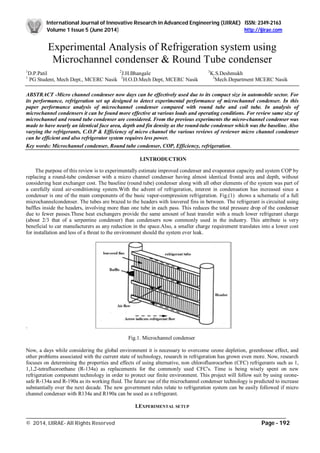
  • 1. International Journal of Innovative Research in Advanced Engineering (IJIRAE) ISSN: 2349-2163 Volume 1 Issue 5 (June 2014) http://ijirae.com _________________________________________________________________________________________________ © 2014, IJIRAE- All Rights Reserved Page - 192 Experimental Analysis of Refrigeration system using Microchannel condenser & Round Tube condenser 1 D.P.Patil 2 J.H.Bhangale 3 K.S.Deshmukh 1 PG Student, Mech Dept., MCERC Nasik 2 H.O.D.Mech Dept, MCERC Nasik 3 Mech.Department MCERC Nasik ABSTRACT -Micro channel condenser now days can be effectively used due to its compact size in automobile sector. For its performance, refrigeration set up designed to detect experimental performance of microchannel condenser. In this paper performance analysis of microchannel condenser compared with round tube and coil tube. In analysis of microchannel condensers it can be found more effective at various loads and operating conditions. For review same size of microchannel and round tube condenser are considered. From the previous experiments the micro-channel condenser was made to have nearly an identical face area, depth and fin density as the round-tube condenser which was the baseline. Also varying the refrigerants, C.O.P & Efficiency of micro channel the various reviews of reviewer micro channel condenser can be efficient and also refrigerator system requires less power. Key words: Microchannel condenser, Round tube condenser, COP, Efficiency, refrigeration. I.INTRODUCTION The purpose of this review is to experimentally estimate improved condenser and evaporator capacity and system COP by replacing a round-tube condenser with a micro channel condenser having almost identical frontal area and depth, without considering heat exchanger cost. The baseline (round tube) condenser along with all other elements of the system was part of a carefully sized air-conditioning system.With the advent of refrigeration, interest in condensation has increased since a condenser is one of the main components of the basic vapor-compression refrigeration. Fig.(1) shows a schematic of a full microchannelcondenser. The tubes are brazed to the headers with louvered fins in between. The refrigerant is circuited using baffles inside the headers, involving more than one tube in each pass. This reduces the total pressure drop of the condenser due to fewer passes.These heat exchangers provide the same amount of heat transfer with a much lower refrigerant charge (about 2/3 that of a serpentine condenser) than condensers now commonly used in the industry. This attribute is very beneficial to car manufacturers as any reduction in the space.Also, a smaller charge requirement translates into a lower cost for installation and less of a threat to the environment should the system ever leak. . Fig.1. Microchannel condenser Now, a days while considering the global environment it is necessary to overcome ozone depletion, greenhouse effect, and other problems associated with the current state of technology, research in refrigeration has grown even more. Now, research focuses on determining the properties and effects of using alternative, non chlorofluorocarbon (CFC) refrigerants such as 1, 1,1,2-tetrafluoroethane (R-134a) as replacements for the commonly used CFC's. Time is being wisely spent on new refrigeration component technology in order to protect our finite environment. This project will follow suit by using ozone- safe R-134a and R-190a as its working fluid. The future use of the microchannel condenser technology is predicted to increase substantially over the next decade. The new government rules relate to refrigeration system can be easily followed if micro channel condenser with R134a and R190a can be used as a refrigerant. I.EXPERIMENTAL SETUP
  • 2. International Journal of Innovative Research in Advanced Engineering (IJIRAE) ISSN: 2349-2163 Volume 1 Issue 5 (June 2014) http://ijirae.com _________________________________________________________________________________________________ © 2014, IJIRAE- All Rights Reserved Page - 193 In this project three types of condenser are used 1.micro channel condenser 2.Round tube condenser 3.Coil- tube condenser In this experiment using refrigerant R134a,cop of refrigerant is calculated . Compressor passes refrigerant to two condenser one after another cop of both the system is thus calculated. Fig 2. Schematic experimental setup Fig 3.Actual setup Fig 4.Actual setup
  • 3. International Journal of Innovative Research in Advanced Engineering (IJIRAE) ISSN: 2349-2163 Volume 1 Issue 5 (June 2014) http://ijirae.com _________________________________________________________________________________________________ © 2014, IJIRAE- All Rights Reserved Page - 194 III.PROCEDURE 1. Connect the two plugs to main. 2. Before ON the supply, conform that all the switches on panel are off position. 3. See the dimmerstat is at zero position. 4. Then put ON the heater switch & give power to heater. 5. This will heat the water in evaporator & this can be seen dial thermometer. 6. Adjust the heater voltage such that the Temperature dial thermometer reading reaches 25 - 300 C.Now ON the D.P. switches. 7. Put ON the condenser fan switch & wait for 2 - 3 minutes. 8. Now switch ON the solenoid valve switch & the compressor switch. 9. The refrigeration flow will start. This can be confirmed on the sight glass. 10. Now the ammeter, voltmeter will show the current & voltage for compressor. 11. Note down the time for 10 revolutions of energy for compression. After some time we will see that the Temperature of water in the evaporator slowly goes down & reaches steady state.( Adjust this temp. at 28 to 300 C). Basic paremeters – 1. HP Condenser pressure in Kg/cm2. = Kg/cm2 2. LP Evaporator Pressure in Kg/Cm2 = Kg/cm2 3. Rotameter in Reading LPH = LPH 4. Condenser Inlet Temperature in 0C = T1 5. Condenser Outlet Temperature 0C = T 6. Evaporator Inlet Temperature in 0C = Tci 7. Evaporator Outlet Temperature 0C = Teo 8. Time for 10 Pulses of heater energymeter = in sec 9. Time for 10 Pulses of comp energymeter = in sec. 10. Ammeter reading = in Amp 11. Voltmeter reading = in V 12. Evaporator Bath Temp in 0C = 0C IV.SPECIFICATIONS 1. COMPRESSOR : Hermetically sealed type Kirloskar Make 1/3 T. Capacity. 2. AIR COOLED CONDENSOR : Copper Coils with fins & cooling fan. 3. EXPANSION DEVICE : i) Thermostatic expansion valve. ii) Capillary Tube 4. EVAPORATOR : Copper Coil immersed in water. The evaporator is installed from outside to prevent heat loss. 5. ENERGY METER : One each for power supply to the Measurement of Compressor & Evaporator Heater. 6. DIMMERSTAT : To control power supply to heater. 7. PRESSURE GAUGE : One each for the measurement of high & low pressure. 8. ELECTRIC HEATER : Immersion type 1.5 Kw 9. DIGITAL TEMPERATURE INDICATOR : To Measure the temperatures at various Points i. e. Evaporator Inlet & Outlet Condenser Inlet & Outlet temperatures of Refrigerant & Evaporator bath Temperature. 10. SOLINOID VALVE : Castle, Italy, Mate. 11. HP & LP CUTOUT : Safety device suitable for the low & high pressure of compressor. 12. SERVICE VALVE : Needle type for changing gas. 13. AMMETER : 0 - 15 Amps for compressor 14. VOLTMETER : 230 V, A.C. for compressor 15. FILTER DRYER : 1 No. 16. THERMOSTAT : Safety Device. 17. SWITCHES : For various controls The refrigerant circuit is mounted on a board. The unit is supported on frame. Do not operate the changing valve. See the sufficient water is filled in the evaporator container. V.OBSERVATIONS 1. Compressor Energymeter Constant (E M C) com = 3200 Pulses/kWatt hr 2. Heater Energymeter Constant ( E M C) h = 3200 Pulses/kwatt hr HP : Condenser Pressure in PSI LP : Evaporator Pressure in PSI Q : Refrigerant flow Rate in LPH
  • 4. International Journal of Innovative Research in Advanced Engineering (IJIRAE) ISSN: 2349-2163 Volume 1 Issue 5 (June 2014) http://ijirae.com _________________________________________________________________________________________________ © 2014, IJIRAE- All Rights Reserved Page - 195 T1 : Refrigerant inlet Temp. To Condenser in 0C T2 : Refrigerant Outlet Temp. from microchannel condenser in 0C T3:; Refrigerant outlet from round tube condenser T4 : Refrigerant outlet from coil-tube condenser T5 : Inlet temperature to evaporator T6 : Outlet from evaporator T7 : Inlet temperature of ice plant T8 : Outlet temperature of ice plant T9 : Bath temperature evaporator1 T10: Atmospheric temperature T11: Air outlet temperature of michrochannel condenser T12: Outlet tc : Time for 10 Pulses of Compressor energy meter in sec. OBSERVATION TABLE Sr. No. Temperature Microchannel condenser Round tube condenser Coil tune condenser I II III I II III I II III 1 T1 56.90 60 61.1 33.9 35.6 36.7 33.7 34.9 35.9 2 T2 32.9 33 33.81 32.83 33.9 34.2 32.8 33.5 34.6 3 T3 33.7 32.7 32.8 32.6 34.4 34.4 32.8 35.1 34.2 4 T4 33.2 33.4 32.7 31.5 37.9 31.8 32.01 36.8 32.2 5 T5 -5 -4.9 -1.8 12.21 15.2 18.6 11.8 14.8 18.3 6 T6 - - - - - - - - - 7 T7 33.4 33.6 34.2 31.8 32.2 32.7 32.1 33.1 31.2 8 T8 31.8 31.9 32.4 29.8 30.5 31.1 30.1 30.7 31.3 9 T9 28.2 22.7 20.2 16.5 14.1 12 19.6 17 13 10 T10 - - - - - - - - - 11 T11 33.2 33.6 34.1 33.4 34.2 34.6 33.2 34.1 34.8 12 T12 30.9 31.2 31.2 32.5 32.8 33.4 31.6 32.2 32.9 Microchannel condenser- Sr.No, Evaporator Compressor Heater Input Temperature Difference After 15 min. Time required for 10 number of pulse V(Volt) I(Amp) T9i (°C) T9f (°C) 1 230 0.901 28.2 24.6 124.47 2 231 0.869 22.7 20.4 190.8 3 215 0.823 20.2 18.4 232 4 229 0.965 31.1 28.7 187 5 230 0.984 30.0 27.4 128 Round tube condenser- Sr.No, Evaporator Compressor Heater Input Temperature Difference After 15 min. Time required for 10 number of pulse V(Volt) I(Amp) T9i (°C) T9f (°C) 1 229 0.965 16.5 14.2 138 2 230 0.984 14.1 12.2 155 3 226 0.938 12.0 9.3 97 4 225 0.935 20.2 18.1 159 5 223 0.965 18.1 16.8 257 Coil tube condenser – Sr.No, Evaporator Compressor Heater Input Temperature Difference After 15 min. Time required for 10 number of pulse V(Volt) I(Amp) T9i (°C) T9f (°C)
  • 5. International Journal of Innovative Research in Advanced Engineering (IJIRAE) ISSN: 2349-2163 Volume 1 Issue 5 (June 2014) http://ijirae.com _________________________________________________________________________________________________ © 2014, IJIRAE- All Rights Reserved Page - 196 1 221 0.920 19.6 17.3 138 2 223 1.001 17 14.1 97 3 224 0.818 13 10.6 143 4 229 0.965 22.3 20.1 130 5 230 0.984 20 18.3 187 VI.CALCULATION Temperature of bath T9 = 19.4 V = 216volt I = 0.793amp Time for 10 pulses (tc) = 2.39 min = 143.4 sec Compressor power – = Nc*3600 Tc*3200 = 10*3600 124.47*3200 =90.38 watt RE = mCp ΔT = 7*4186*(28.2-24.6) Time 15*60 = 117.208 watt COP= RE Compressor power = 117.208 90.38 Cop=1.298 Carnot COP i) Suction LP=31PSI=(31*0.0731)+1.013 SuctionLP=3.279kg per cm2 TL=2 °C TL=275K ii) Delivery HP=141PSI =(141*0.0731)+1.013 =10.927 kg per sq.cm TH= 45 °C TH=318K Carnot COP= = TL TH – TL = 275 318- 275 = 6.39 Efficiency = Actual COP = 1.298 *100 Carnot COP 6.39 = 20.31 % VII.RESULT TABLE Microchannel condenser – Sr. no. Evaporator Compressor Coefficient of Performance Carnot COP Efficiency Heat supplied to Evaporator Compressor Work Qevap (RE) Load Wc COP 1 117.208 90.38 1.298 6.39 20.31 2 74.88 59.2 1.27 6.41 19.81 3 58.60 48.49 1.208 6.50 18.58 4 78.13 60.1 1.3 6.35 20.47 5 84.60 87.21 0.97 6.43 15.08
  • 6. International Journal of Innovative Research in Advanced Engineering (IJIRAE) ISSN: 2349-2163 Volume 1 Issue 5 (June 2014) http://ijirae.com _________________________________________________________________________________________________ © 2014, IJIRAE- All Rights Reserved Page - 197 Round tube condenser- Sr. no. Evaporator Compressor Coefficient of Performance Carnot COP Efficiency Heat supplied to Evaporator Compressor Work Qevap (RE) Load Wc COP 1 74.88 81.5 0.92 6.571 14.15 2 58.604 72.58 0.81 6.0 13.5 3 84.906 115.97 0.76 6.39 11.89 4 68.37 70.48 0.95 6.01 15.80 5 42.32 43.62 0.97 5.70 17.01 Coil-tube condenser – Sr. no. Evaporator Compressor Coefficient of Performance Carnot COP Efficiency Heat supplied to Evaporator Compressor Work Qevap (RE) Load Wc COP 1 74.88 81.52 0.92 6.5 14.15 2 94.41 115.97 0.814 6 13.5 3 68.37 78.67 0.869 6.39 11.89 4 71.62 86.28 0.83 6.3 13.17 5 55.34 60.15 0.92 5.8 45.86 VIII. Graph Efficiency: Micro channel Condenser- Roundtube Condenser- 17.5 18 18.5 19 19.5 20 20.5 21 efficiency Mirochannel Condenser Mirochannel efficiency Load 0 5 10 15 20 74.88 58.604 87.906 68.37 42.32 efficiency Roundtube Condenser Roundtube efficiency Load
  • 7. International Journal of Innovative Research in Advanced Engineering (IJIRAE) ISSN: 2349-2163 Volume 1 Issue 5 (June 2014) http://ijirae.com _________________________________________________________________________________________________ © 2014, IJIRAE- All Rights Reserved Page - 198 Coil tube condenser- IX.CONCLUSION In this study, air-conditioning systems with a micro-channel condenser and a round-tube condenser and coil tube were experimentally examined. These three condensers hadalmost identical frontal area and depth because the purpose of this study was to measure performance improvement using the micro-channel condenser which had an almost identical package volume as the round-tube condenser. An economic issue such as heat exchanger cost was not considered. Significant performance improvement was presented for the system with the micro-channel condenser. The COP of the system with the microchannel condenser is around 7-8% higher than that with the round condenser in ARI A condition. Also, using a micro-channel condenser resulted in a 2.5 ᵒC lower condensing temperature and decreased the refrigerant pressure drop from 166 kPa in the round-tube condenser to 57 kPa in the micro-channel condenser. The refrigerant charge amount for the system with the micro- channel condenser was 9.2% smaller than that with the roundtube condenser. Even though the micro-channel condenser showed better heat transfer performance of capacity and system COP than the round-tube condenser, the round tube condenser has a cost advantage at this point in time. The micro-channel condenser was also investigated using a numerical model. The model could estimate the condenser capacity accurately. From the simulation results, it could be calculated that the consideration of non-uniform distribution for the air and refrigerant did not make a significant difference for predicting the condenser capacity. However, this small influence of non-uniform air and refrigerant on capacity is valid only for the microchannel condenser examined in this study. The air and refrigerant mal-distribution effect on heat exchanger capacity is different according to the types of heat exchanger (microchannel or round tube), the usage of heat exchanger (evaporators or condensers), and the circuit geometry of heat exchangers. X.REFERENCES [1] ANSI/ASHRAE Standard 37-2005, 2005. Method of Testing for Rating Electrically Driven Unitary Air- Conditioning and Heat Pump Equipment. American Society of Heating, Refrigerating and Air-Conditioning Engineers, Inc., Atlanta, GA, USA. [2] ARI Standard 210/240, 2003. Standard for Unitary Air Conditioning and Air Source Heat Pump Equipment. Air Conditioning and Refrigeration Institute, Arlington, VA, USA. [3]. Aganda, A.A., Coney, J.E.R., Sheppard, C.G.W., 2000. Airflow maldistribution and the performance of a packaged air conditioning unit evaporator. Appl. Therm. Eng. 20, 515–528. [4]. Beaver, A.C., Yin, J.M., Bullard, C.W., Hrnjak, P.S., 1999. An experimental Investigation of Transcritical Carbon dioxide Systems for Residential Air-Conditioning. [5]. ACRC Report CR-18.University of Illinois at Urbana-Champaign, Urbana, IL, USA. [6]. Brix, W., Jakobsen, A. Rasmussen, B.D., Carlsen, H., 2007.Analysis of air flow distribution in refrigeration system. In:International Congress of Refrigeration, ICR07-B2-581, Beijing. [7]. Chang, Y.J., Wang, C.C., 1997. A generalized heat transfer correlation for louver fin geometry. Int. J. Heat Mass Transfer 40, 533–544. [8]. Choi, J.M., Payne, W.V., Domanski, P.A., 2003. Effects of non-uniform refrigerant and air flow distributions on finned-tube evaporator performance. In:International Congress of Refrigeration, ICR0040, Washington DC. [9]. Domanski, P.A., 1991. Simulation of an evaporator with non-uniform onedimensional air distribution. ASHRAE Trans.97, 793–802. [10]. Elbel, S., Hrnjak, P.S., 2004. Flash gas bypass for improving the performance of transcritical R744 systems that useMicro-channel evaporators. Int. J. Refrigeration 27, 724–735. [11]. Friedel, L., 1979. Improved friction pressure correlation for horizontal and vertical two-phase pipe flow. In: The EuropeanTwo-Phase Flow Group Meeting, paper E2, Ispra, Italy. [12]. Fagan, T.J., 1980. The effects of air flow maldistributions on air to refrigerant heat exchanger performance. ASHRAE Trans.86, 699– 713. [13]. Hrnjak, P.S., 2002. Micro-channel Heat Exchangers as a Design Option for Charge Reduction in NH3 and HC Systems. Zero Leakage-Minimum Charge. IIR/IIF, Stockholm, p. 91. Incropera, F.P., DeWitt, D.P., 2002. [14]. Fundamentals of Heat and Mass Transfer, fifth ed. John Wiley & Sons, New York. [15]. Kandlikar, S.G., 2002. Fundamental issues related to flow boiling in minichannel sand microchannels. Exp. Therm. Fluid Sci. 26,389– 407. [16]. Klein, S.A., 2005. Engineering Equation Solver. Academic professional V7.457- 3D. F-Chart Software,Madison, WI, USA. 0 5 10 15 20 74.88 94.41 68.37 71.62 55.34 efficiency Coil tube Condenser Coil tube efficiency