Lec07 Analysis and Design of Doubly Reinforced Beam (Reinforced Concrete Design I & Prof. Abdelhamid Charif)
•
14 gostaram•4,975 visualizações

Lec07 Analysis and Design of Doubly Reinforced Beam (Reinforced Concrete Design I & Prof. Abdelhamid Charif)

Recomendados
Recomendados
Mais conteúdo relacionado
Mais procurados
Mais procurados (20)
Semelhante a Lec07 Analysis and Design of Doubly Reinforced Beam (Reinforced Concrete Design I & Prof. Abdelhamid Charif)
Semelhante a Lec07 Analysis and Design of Doubly Reinforced Beam (Reinforced Concrete Design I & Prof. Abdelhamid Charif) (20)
Mais de Hossam Shafiq II
Mais de Hossam Shafiq II (20)
Último
Último (20)
Lec07 Analysis and Design of Doubly Reinforced Beam (Reinforced Concrete Design I & Prof. Abdelhamid Charif)
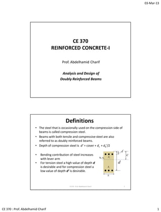
- 1. 03-Mar-13 CE 370 : Prof. Abdelhamid Charif 1 CE 370 REINFORCED CONCRETE-I Prof. Abdelhamid Charif Analysis and Design of Doubly Reinforced Beams Definitions • The steel that is occasionally used on the compression side of beams is called compression steel. • Beams with both tensile and compressive steel are also referred to as doubly reinforced beams. • Depth of compression steel is d’ = cover + ds + db’/2 2 d b sA N.A. ' d ' sA c CE370 : Prof. Abdelhamid Charif • Bending contribution of steel increases with lever arm • For tension steel a high value of depth d is desirable and for compression steel a low value of depth d’ is desirable.
- 2. 03-Mar-13 CE 370 : Prof. Abdelhamid Charif 2 Why use compression steel ? • Compression steel is not normally required in beams because high compressive strength of concrete decreases the need for such reinforcement. • Occasionally, however, space or aesthetic requirements limit beams to such sizes that compression steel is needed in addition to tensile steel. • A beam designed with tension steel only but not satisfying tension-control condition (εt < 0.005) must either have compression reinforcement or increased dimensions. • Compression steel may also be provided for practical reasons only (to fix stirrups and prevent their movement during casting and vibration) 3CE370 : Prof. Abdelhamid Charif Why use compression steel ? (cont.) • Compressive steel increases moment capacity of RC sections as well as their ductility (higher ultimate curvature). • Though expensive, compression steel makes beams tough and ductile, enabling them to withstand large moments, deformations, and stress reversals such as might occur during earthquakes. • Many codes for earthquake zones require that certain minimum amounts of compression steel be included in flexural members. • Compression steel reduces long-term deflections due to shrinkage and plastic flow. • Tests of doubly reinforced concrete beams have shown that even if the compression concrete crushes, the beam may very well not collapse if the compression steel is enclosed by stirrups. 4CE370 : Prof. Abdelhamid Charif
- 3. 03-Mar-13 CE 370 : Prof. Abdelhamid Charif 3 5 Effect of compression steel on sustained load deflection bd A' s ratiosteelnCompressio' CE370 : Prof. Abdelhamid Charif 6 Effect of compression steel on ductility Limited effect on strength CE370 : Prof. Abdelhamid Charif Sometimes the neutral axis is close to the compression steel, the strain and stress are therefore very small. Thus compression steel adds little moment capacity to the beam. It can, however, increase beam ductility and reduce long term deflections.
- 4. 03-Mar-13 CE 370 : Prof. Abdelhamid Charif 4 CE 370 REINFORCED CONCRETE-I Prof. Abdelhamid Charif Analysis of RC Beams with Compression Steel Analysis of RC beams with compression steel • In beams with compression steel (doubly reinforced), the amount of tension steel is high (almost maximum). There is normally no need to check minimum steel • Flanges in T-beams provide extra compression capacity. T-beams do not usually require compression steel • Analysis and design of doubly reinforced beams is therefore limited to rectangular sections. 8CE370 : Prof. Abdelhamid Charif
- 5. 03-Mar-13 CE 370 : Prof. Abdelhamid Charif 5 Strain Compatibility in Doubly Reinforced Beams Tension steel in one layer or more. Compression steel in one layer. Tensile steel assumed yielding but in analysis problems, this may be untrue Compression steel may yield or not. Strain expressions are derived from strain compatibility of plane sections (use of similar triangles). 9 d b sA N.A. 003.0 t ' s'd ' sA c td s mind min • As , d , εs = Area, depth and strain at tension steel centroid • dt , εt = Depth and strain at bottom tension layer (max. depth) • dmin , εmin = Depth and strain at minimum depth tension layer • A’s , d’ , ε’s = Area, depth and strain at compression steel CE370 : Prof. Abdelhamid Charif Strain Compatibility in Doubly Reinforced Beams 10 Strain expressions are derived using similar triangles : ysy ysss s s t t s f E f c dc c cd c cd c cd ' '' ' ' min min if if :stresssteelnCompressio ' 003.0:nCompressio 003.0:iondepth tensMin. 003.0:tensionBottom 003.0:tensionCentroid d b sA N.A. 003.0 t ' s'd ' sA c td s mind min CE370 : Prof. Abdelhamid Charif
- 6. 03-Mar-13 CE 370 : Prof. Abdelhamid Charif 6 11 (a) Section a abfC cc ' 85.0 ' 85.0 cf ys fAT (*)''' sss fAC d b sA N.A. 003.0 ' s'd ' sA c s (b) Strains (c) Forces Forces in Doubly Reinforced Beams ''' '' ' 85.0:concretedisplacedforaccountTo concrete)displacedconsider(modify to:forcencompressioSteel 85.0:forcencompressioConcrete assumed)yielding(tensile:forcetensionSteel csss sss cc ys ffAC fAC abfC fAT (*) Compression steel area displaces same area of concrete CE370 : Prof. Abdelhamid Charif Displaced Concrete • Compression steel bars displace an equal amount (area) of compression concrete. • The concrete compression force is therefore slightly reduced 12 ''' '''''' '' 85.0 85.0 :forceecompressivsteelthecorrectingbyaccountintoit taketoconvenientmorethereforeisItarm.leversametheehasand levelsteelncompressioat thelocatedisconcretedisplacedThis 85.0reductionForce csss scssssss sc ffAC AfAfCAfC Af CE370 : Prof. Abdelhamid Charif
- 7. 03-Mar-13 CE 370 : Prof. Abdelhamid Charif 7 13 (a) Section a abfC cc ' 85.0 ' 85.0 cf ys fAT '''' 85.0 csss ffAC d b sA N.A. 003.0 ' s'd ' sA c s (b) Strains (c) Forces Moment in Doubly Reinforced Beams ''''' '''' 85.0 2 85.0 steelileabout tensforcesncompressioofMomentmomentNominal 85.085.0:mequilibriuForce ddffA a dabfM ffAabffACCT csscn csscyssc CE370 : Prof. Abdelhamid Charif 14 Nominal Moment in Doubly Reinforced Beams eq.(b)''''' 85.0 2 85.0momentNominal ddffA a dabfM csscn eq.(a) bf ffAfA a ffAabffACCT c csys csscyssc s ' ''' '''' 85.0 85.0 :thusisdepthblockStress 85.085.0:mequilibriuForce ysy ysss s f E f ' '' ' if if :stresssteelnCompressio notoryieldedhassteelncompressiowhetherisdifficultymainThe CE370 : Prof. Abdelhamid Charif
- 8. 03-Mar-13 CE 370 : Prof. Abdelhamid Charif 8 Analysis of Doubly Reinforced Beams • Assume tension steel has yielded • Assume compression steel has yielded • Compute stress block depth a and neutral axis depth c • Compute compression and tension steel strains • If compression and tension steel have yielded, OK continue, perform strain checks and compute nominal moment • If compression steel has not yielded, express unknown stress block depth and compression steel stress in terms of neutral axis depth c and solve resulting quadratic equation. Perform strain checks and compute nominal moment. • If tension steel has not yielded, use adapted method 15CE370 : Prof. Abdelhamid Charif Analysis of Doubly Reinforced Beams (Compression steel has yielded) 16 c cd c dc a c bf ffAfA bf ffAfA a fff ss c cysys c csys yss s 003.0,003.0:strainsSteel 85.0 85.0 85.0 85.0 :eq.(a)fromdepthblockstressCompute :yieldedhavesteeltensionandncompressioAssume ' ' 1 ' '' ' ''' ' '''' 85.0 2 85.0 :eq.(b)hmoment witnominalcompute :thenassumed,as,yieldedhavesteeltensionandncompressioIf ddffA a dabfM cyscn CE370 : Prof. Abdelhamid Charif
- 9. 03-Mar-13 CE 370 : Prof. Abdelhamid Charif 9 Analysis of Doubly Reinforced Beams (Compression steel has not yielded) (1) 17 '''' '' '' ''' 85.085.0 :equationmequilibriuforceBack to 600003.0200000 :yieldednothassteelncompressioIf csscyssc ysss sssys ffAabffACCT f c dc c dc Ef Ef 085.060085.0 85.060085.0 '' ' ' 1 ' ' ' ' 1 ' ysscsc cscys fAAf c dc Acbf f c dc AcbffA Substituting the stress block depth (a = β1c) and the compression steel stress in terms of neutral axis depth gives: CE370 : Prof. Abdelhamid Charif Analysis of Doubly Reinforced Beams (Compression steel has not yielded) (2) 18CE370 : Prof. Abdelhamid Charif Multiplying all terms by c and assembling leads to a quadratic equation with respect to the neutral axis depth c : eq.(b)''''' 2'' '''' 1 ' ' 1 ' ' ' 1 ' ''''2 85.0 2 85.0:OKIf yieldncompressionoandyieldioncheck tensandstrainssteelCompute 1 4 1 2 :issolutionpositiveThe 85.0 600 85.0 with 0 ddffA a dabfM RPP dPRPP c b A R bf A P bf fA P dPcRPPc csscn s c s c ys
- 10. 03-Mar-13 CE 370 : Prof. Abdelhamid Charif 10 19 Analysis Problem-1 MPa20andMPa420 shownbeamtheofcapacitymomentdesigntheDetermine ' cy ff All dimensions in mm 750 350 60' d 202 324 624 66 684d mm d dd mm d dhd b s b s 60 2 20 1004 2 cover' 68466750 2 32 1004750 2 cover ' 2 2 ' 2 2 3.628 4 20 2 0.3217 4 32 4 mmA mmA s s CE370 : Prof. Abdelhamid Charif 20 ysys ff '' :yieldedhassteelncompressioAssume mma bf ffAfA a c cysys 527.184 3502085.0 2085.04203.6284200.3217 85.0 85.0 :depthblockstressCompute ' '' yieldingassumedOK0021.000217.0 09.217 6009.217 003.0003.0:strainsteelnCompressio 09.217 85.0 527.184 :depthN.A. '' ' ' 1 yss s c dc mm a c Solution 1 control-OK tension005.000645.0 09.217 09.217684 003.0003.0:strainTension tt t t c cd CE370 : Prof. Abdelhamid Charif
- 11. 03-Mar-13 CE 370 : Prof. Abdelhamid Charif 11 21 mkNM mkNmmNM M ddffA a dabfM n n n csscn .9.7267.80790.0momentDesign .7.807.107.807 606842085.04203.628 2 527.184 684350527.1842085.0 85.0 2 85.0 :eq.(b)usingmomentNominal 6 ''''' Solution 1 – Cont. CE370 : Prof. Abdelhamid Charif 22 Analysis Problem-2 Analysis of a rectangular section 300 x 600 mm with six 20-mm bars in two layers as tension steel and three 20-mm bars as compression reinforcement. Net spacing between steel layers is 30 mm. Stirrups have 10-mm diameter MPafMPaf yc 42025' 2' 2 21 2min 12 1 48.942 96.1884 515 2 490 4905054020 54060 60101040' mmA mmA mm dd d mmdd mmSdd mmhdd mmd s s l t d 300 206 'd 203 td 600mind CE370 : Prof. Abdelhamid Charif
- 12. 03-Mar-13 CE 370 : Prof. Abdelhamid Charif 12 23 ysys ff '' :yieldedhassteelncompressioAssume mma bf ffAfA a c cysys 09.62 3002585.0 2585.042048.94242096.1884 85.0 85.0 :depthblockstressCompute ' '' yieldingNot0021.0000536.0 05.73 6005.73 003.0003.0:strainsteelnCompressio 05.73 85.0 09.62 :depthN.A. '' ' ' 1 yss s c dc mm a c Solution 2 CE370 : Prof. Abdelhamid Charif Solution 2 – Cont. (Compression steel has not yielded) 24CE370 : Prof. Abdelhamid Charif Neutral axis depth is the solution of a quadratic equation : mmc c P RP b A R bf A P bf fA P RPP dPRPP c s c s c ys 046.105 1 696.335765.1041007.146 6035765.1044 1 2 696.335765.1041007.146 35765.104 85.03002585.0 48.942600 696.3 85.0300 48.942 1007.146 85.03002585.0 42096.1884 85.0 600 85.0 with 1 4 1 2 2 ' ' 1 ' ' 1 ' ' ' 1 ' 2'' ''''
- 13. 03-Mar-13 CE 370 : Prof. Abdelhamid Charif 13 Solution 2 – Cont. (Compression steel has not yielded old) 25 control-OK tensionandyieldOK005.0and 011.0 046.105 046.105490 003.0 003.0:depthminimumatstrainTension )420(293.257 046.105 60046.105 600600 yieldingnotOK0021.000129.0 046.105 60046.105 003.0003.0:strainsteelnCompressio mm105.046c minmin min min min ' ' s '' ' ' y y yss s c cd MPafMPa c dc f c dc CE370 : Prof. Abdelhamid Charif Solution 2 – Cont. (Compression steel has not yielded) 26 mkNM mkNmmNM M mmcaMPaf ddffA a dabfM n n n csscn .06.33295.36890.0:momentDesign .95.368.1095.368 605152585.0293.25748.942 2 289.89 515300289.892585.0 289.89046.10585.0and293.257:with 85.0 2 85.0:eq.(b)frommomentNominal 6 1 ' s ''''' CE370 : Prof. Abdelhamid Charif
- 14. 03-Mar-13 CE 370 : Prof. Abdelhamid Charif 14 27 Observations about effect of compression steel : • Three compression steel bars (50% of tension steel) have added 9.36 kN.m (2.9%) only to the beam flexural capacity, because of the reduced stress (61 % of yield value). • Little advantage in strength from compression steel • Main advantage of compression steel is in increasing ductility and reducing long term deflections mkNM mkNM n n .06.33295.36890.0:momentDesign .95.368:momentNominal Discussion – Effect of compression steel mkNM mkNM n n .70.322559.35890.0:momentDesign .559.358:momentNominal :steelncompressiowithoutbeamSame CE370 : Prof. Abdelhamid Charif 28 Analysis Problem-3 Analysis of a rectangular section 250 x 600 mm with six 28-mm bars in two layers as tension steel and two 20-mm bars as compression reinforcement. Net spacing between steel layers is 28 mm. Stirrups have 10-mm diameter MPafMPaf yc 42018' 2' 2 21 12min 1 3.628202 5.3694286 508 2 4805653628 536141040 60101040' mmA mmA mm dd d mmSddd mmhdd mmd s s l t CE370 : Prof. Abdelhamid Charif d 250 286 'd 202 td 600mind
- 15. 03-Mar-13 CE 370 : Prof. Abdelhamid Charif 15 29 yielding)notlayersboth(yieldingnotsteelTension00103.0 05.399 05.399536 003.0003.0:strainsteelTension yieldingncompressioOK0021.000255.0 05.399 6005.399 003.0003.0:strainsteelnCompressio 05.399 85.0 19.339 :depthN.A. 19.339 2501885.0 1885.04203.6284205.3694 85.0 85.0 :depthblockstressCompute :yieldedhassteelncompressioAssume 1 1 '' ' ' 1 ' '' '' yt t yss s c cysys ysys c cd c dc mm a c mma bf ffAfA a ff Solution 3 CE370 : Prof. Abdelhamid Charif Analysis of Doubly Reinforced Beams Tension steel has not yielded 30CE370 : Prof. Abdelhamid Charif As shown in the previous problem 3, tension steel does not yield when the neutral axis depth is rather large, which usually leads to yielding of the compression steel. We therefore assume initially that compression steel has yielded. d b 1 2 s s A A 'd ' sA 1d2d Lumping of tension layers cannot be used since there is no yielding. We treat the case of problem 3 with two tension layers in a general way using strain compatibility. Both tension layers are not yielding. 2 21 25.1847283 mmAA ss
- 16. 03-Mar-13 CE 370 : Prof. Abdelhamid Charif 16 CE370 : Prof. Abdelhamid Charif 31 yss ssss ss ff c dc c cd f c cd Ef c cd c cd '' 2 2 1 11 2 2 1 1 ' 003.0:stressstrain /nCompressio 600600:stressesTension 003.0003.0:strainsTension Analysis of Doubly Reinforced Beams Tension steel has not yielded – Cont. a abfC cc ' 85.0 ' 85.0 cf 111 ss fAT ''' 85.0 cyss ffAC 2d b 1 2 s s A A N.A. 003.0 ' s'd ' sA c 1 2 s s 1d 222 ss fAT CE370 : Prof. Abdelhamid Charif 32 c cd A c cd AffAcbf TTCC h dT h dTd h C ah CM sscysc sc scn 2 2 1 1 '' 1 ' 21 2211 600600)85.0(85.0 :mequilibriuForce 22 ' 222 :centroidsectionaboutcomputedmomentNominal Analysis of Doubly Reinforced Beams Tension steel has not yielded – Cont. a abfC cc ' 85.0 ' 85.0 cf 111 ss fAT ''' 85.0 cyss ffAC 2d b 1 2 s s A A N.A. 003.0 ' s'd ' sA c 1 2 s s 1d 222 ss fAT
- 17. 03-Mar-13 CE 370 : Prof. Abdelhamid Charif 17 CE370 : Prof. Abdelhamid Charif 33 1 )( )(4 1 2 :issolutionpositiveThe 85.0 )85.0( 85.0 600 85.0 600 0)( :asexpressed-rebecanhichequation wQuadratic 0)(600)(600)85.0(85.0 600600)85.0(85.0 2 21 221121 1 ' '' 1 ' 2 2 1 ' 1 1 221121 2 221121 ''2 1 ' 2 2 1 1 '' 1 ' QPP dPdPQPP c bf ffA Q bf A P bf A P dPdPcQPPc dAdAcAAffAcbf c cd A c cd AffAcbf c cys c s c s sssscysc sscysc Analysis of Doubly Reinforced Beams Tension steel has not yielded – Cont. CE370 : Prof. Abdelhamid Charif 34 mmc c QPP dPdPQPP c bf ffA Q bf A bf A PP c cys c s c s 54.320 1 )21.789.3409.340( )4809.3405369.340(4 1 2 21.789.3409.340 1 )( )(4 1 2 :issolutionpositiveThe 21.78 85.02501885.0 )1885.0420(3.628 85.0 )85.0( 9.340 85.02501885.0 25.1847600 85.0 600 85.0 600 :3problemfornapplicatioNumerical 2 2 21 221121 1 ' '' 1 ' 2 1 ' 1 21 Analysis of Doubly Reinforced Beams Tension steel has not yielded – Solution 3 - Cont.
- 18. 03-Mar-13 CE 370 : Prof. Abdelhamid Charif 18 CE370 : Prof. Abdelhamid Charif 35 kN c cd ATkN c cd AT kNffACkNcbfC MPaffMPaEfMPaEf c dc c cd c cd mmc ss cysscc ysssssss ys ys ys 37.55160001.745600 27.254)85.0(16.104285.0 420,48.298,3.403 OK00244.0 54.320 6054.320 003.0 ' 003.0 OK0014924.0 54.320 54.320480 003.0003.0 OK0020165.0 54.320 54.320536 003.0003.0 :forcesandstressesstrains,variousCompute54.320 2 22 1 11 '' 1 ' ' 2211 ' 2 2 1 1 Analysis of Doubly Reinforced Beams Tension steel has not yielded – Solution 3 - Cont. CE370 : Prof. Abdelhamid Charif 36 mkNM mkNM h dT h dTd h C ah CM n n scn .40.32978.50665.0 yielding)(No65.0 .78.506:obtainon wesubstitutiAfter 22 ' 222 :momentNominal 2211 a 16.1042cC ' 85.0 cf 01.7451 T 27.254sC 2d b 1 2 s s A A N.A. 003.0 ' s'd ' sA c 1 2 s s 1d 37.5512 T Analysis of Doubly Reinforced Beams Tension steel has not yielded – Solution 3 - Cont.
- 19. 03-Mar-13 CE 370 : Prof. Abdelhamid Charif 19 CE 370 REINFORCED CONCRETE-I Prof. Abdelhamid Charif Design of doubly reinforced beams according to ACI and SBC 304 RC design of beams with compression steel according to ACI and SBC 304 • If a section, designed with tension steel only, is not tension- controlled, compression steel is then required. • The solution is to set tension steel strain equal to minimum value of 0.005 and then design accordingly. • The neutral axis depth and strains become therefore all known. • With many tension layers, satisfying tension-control at the bottom layer will in general satisfy yield condition at the tension steel layers. • If however it is suspected that this might not be true, then the neutral axis depth will be chosen to satisfy both conditions. 38CE370 : Prof. Abdelhamid Charif
- 20. 03-Mar-13 CE 370 : Prof. Abdelhamid Charif 20 39 y yy d cc 10003 3 :depthminimumsteelatYield min min t t tt d d cc 375.0 8 3 005.0 :layerbottomatcontrol-Tension y t dd c 10003 3 , 8 3 Min :conditionsbothSatisfying min RC design of beams with compression steel according to ACI and SBC 304 d b sA N.A. 003.0 005.0t ' s ' sA c td s mind y min CE370 : Prof. Abdelhamid Charif 40 RC design of beams with compression steel Design steps cβa dd c y t 1 min knownthusisblockstressecompressivconcreteofDepth steeltensilemaximumProviding 10003 3 , 8 3 Min conditionsstrainsteelnsionsatisfy tetoaxisneutralSet the2/ layersofnumberexpectedtoaccordingdepthsvariousEstimate1/ continuerequired,steelnCompressioIf onlysteelh tensionDesign wit required,notsteelnCompressioIf 2 85.0 :steelncompressiohoutmoment witnominalCompute3/ 0 0 ' 0 un un cn MM MM a dabfM CE370 : Prof. Abdelhamid Charif
- 21. 03-Mar-13 CE 370 : Prof. Abdelhamid Charif 21 41 RC design of beams with compression steel Design steps – Cont. ''' ' ' ''''' 85.0 2 85.0 :areasteelncompressioRequired 85.0 2 85.0 settingbyareasteelncompressiorequiredDetermine5/ ddff a dabf M A ddffA a dabf M M MM cs c u s cssc u n un MPaEf ff c dc ssssys ysys s '''' '' ' 200000If If ' 003.0 :stressandstrainsteelnCompressio4/ CE370 : Prof. Abdelhamid Charif 42 RC design of beams with compression steel Design steps – Cont. y cssc s csscyssc f ffAabf A ffAabffACCT '''' '''' 85.085.0 :areasteeltensionRequired 85.085.0 mequilibriuforceusingareasteeltensionrequiredDetermine6/ CE370 : Prof. Abdelhamid Charif Although the tension control condition is enforced from the start, the actually provided steel areas (when choosing bar numbers) may violate this condition and strain checks are therefore required. The provided tension steel area must not be excessive as compared to the required value. This topic will be elaborated later.
- 22. 03-Mar-13 CE 370 : Prof. Abdelhamid Charif 22 43 Design Problem-1 85.0MPa30andMPa420 kN.m510andkN.m753 1 ' cy LD ff MM mmd mmdd mmdd mmhd t 70' 67030 73030 700100 min CE370 : Prof. Abdelhamid Charif 800 375 'd ' sA sA d Expecting two tension steel layers, the various steel depths are estimated as : Design the shown 375 x 800 mm rectangular beam subjected to the following dead and live moments : kN.mM MMM u LDu 0.1392 )510(7.1)375(4.17.14.1:momentUltimate 44 Solution 1 mmca mmc dd c y t 6875.23275.27385.0 75.27312.394,75.273Min 0021.010003 6703 , 8 7303 Min 10003 3 , 8 3 Min conditionssteelnsionsatisfy tetoaxisneutralSet the 1 min requiredsteelnCompressio).1392( .8.11687.12989.0 .7.1298.107.1298 2 6875.232 7003756875.2323085.0 2 85.0 :steelncompressiohoutmoment witNominal 0 0 6 0 ' 0 mkNMM mkNM mkNmNM a dabfM un n n cn CE370 : Prof. Abdelhamid Charif
- 23. 03-Mar-13 CE 370 : Prof. Abdelhamid Charif 23 45 Solution 1 – Cont. MPaff c dc ysys s 420)0021.0( 00223.0 75.273 7075.273 003.0 ' 003.0 :stressandstrainsteelnCompressio '' ' )4.1140223(8.997 707003085.0420 2 6875.232 7003756875.2323085.0 90.0 101392 85.0 2 85.0 :areasteelncompressioRequired 22' 6 ' ''' ' ' mmmmA A ddff a dabf M A s s cs c u s CE370 : Prof. Abdelhamid Charif Solution 1 – Cont. 46 )0.6434328(0.6235 420 3085.04208.9973756875.2323085.0 85.085.0 :areasteeltensionRequired 22 '''' mmmmA A f ffAabf A s s y cssc s CE370 : Prof. Abdelhamid Charif 4.1140223/8.997 :)(steelncompressioActual/Required 0.6434328/0.6235 :)(steeltensionActual/Required ' 2 2 s s A mm A mm 800 375 'd 223 328 d
- 24. 03-Mar-13 CE 370 : Prof. Abdelhamid Charif 24 Using 32 mm for bar spacing (not less than bar diameter), and 10 mm stirrups, the maximum number of 32-mm bars in one layer is: 4 67.4 3232 0423210632375 cover26 max n n Sd ddSb n bb bsb 47 Two layers are therefore required as assumed (4+4). For layer spacing, we use 30 mm. Solution 1 – Cont. 800 375 'd 223 328 d CE370 : Prof. Abdelhamid Charif 48 Solution 1 – Cont. 375 'd 223 328 d 4.1140223/8.997:)(steelncompressioActual/Required 0.6434328/0.6235:)(steeltensionActual/Required '2 2 s s Amm Amm mm d dd mm dd d mmdSddd mmdd d dhdd b s bl t b st 61111040 2 cover' 703 2 6723230734 734161040800 2 cover ' 21 1min2 1 1 The difference between the required and provided values of steel areas may lead to violation of the tension control condition. Strain checks are therefore required using actual steel areas and depths .
- 25. 03-Mar-13 CE 370 : Prof. Abdelhamid Charif 25 CE370 : Prof. Abdelhamid Charif 49 Solution 1 – Cont. 375 'd 223 328 d mmd mm dd d mmdd mmdd t 61' 703 2 672 734 21 min2 1 The actual tension steel depths are slightly greater than was initially safely assumed. The actual compression steel depth is less than was assumed and this also is on the safe side. The steel strain checks are however still required because of the excess in the provided steel areas. 50 ysys ff '' :yieldedhassteelncompressiothatbeforefoundwasasAssume yieldingassumedOK0021.000234.0 11.277 6111.277 003.0003.0:strainsteelnCompressio 11.277 85.0 54.235 :depthN.A. 54.235 3753085.0 3085.04204.11404200.6434 85.0 85.0 :depthblockstressactualCompute '' ' ' 1 ' '' yss s c cysys c dc mm a c mma bf ffAfA a CE370 : Prof. Abdelhamid Charif Solution 1 – Cont.
- 26. 03-Mar-13 CE 370 : Prof. Abdelhamid Charif 26 51 Solution 1 – Cont. CE370 : Prof. Abdelhamid Charif control-tensionOKNOT005.000495.0 00495.0 11.277 11.277734 003.0003.0 :layer)(bottomdepthmaximumatcheckcontrolTension yieldOK0043.0 11.277 11.277672 003.0003.0 :depthminimumatcheckYield min min t t t y c cd c cd The section turns out to be not tension controlled because in the provided steel areas, there was more excess in the tension steel: 2' 2 6.1428.9974.1140:nCompressio 0.19900.62350.6434:Tension :Required-ProvidedareasteelExcess mmA mmA s s CE370 : Prof. Abdelhamid Charif 52 Solution 1 – Cont. 375 'd 282 328 d 2' 2 '2 2 7.2338.9975.1231:nCompressio 0.19900.62350.6434:Tension 5.1231282/8.997:)(steelncompressioActual/Required 0.6434328/0.6235:)(steeltensionActual/Required mmA mmA Amm Amm s s s s mm d dd mmddd mmddmmdd b s t 64141040 2 cover' :depthsteelncempressioNew 7032/)( 672734 :beforeasaredepthssteelTension ' 21 min21 Let us now try another solution with more excess in compression steel (keeping the same bar reinforcement in tension):
- 27. 03-Mar-13 CE 370 : Prof. Abdelhamid Charif 27 53 ysys ff '' :yieldedhassteelncompressioagain thatAssume yieldingassumedOK0021.00023.0 689.272 64689.272 003.0003.0:strainsteelnCompressio 689.272 85.0 786.231 :depthN.A. 786.231 3753085.0 3085.04205.12314200.6434 85.0 85.0 :depthblockstressactualCompute '' ' ' 1 ' '' yss s c cysys c dc mm a c mma bf ffAfA a CE370 : Prof. Abdelhamid Charif Solution 1 – Cont. 54 Solution 1 – Cont. CE370 : Prof. Abdelhamid Charif control-tensionOK005.000508.0 689.272 689.272734 003.0 003.0:layer)(bottomdepthmaximumatcheckcontrolTension yieldOK00439.0 689.272 689.272672 003.0003.0 :depthminimumatcheckYield min min t t t y c cd c cd OKmkNMM mkNmmNM M ddffA a dabfM un n n csscn .0.13923.148974.16549.0momentDesign .74.1654.1074.1654 647033085.04205.1231 2 786.231 703375786.2313085.0 85.0 2 85.0:(optional)checkMoment 6 '''''
- 28. 03-Mar-13 CE 370 : Prof. Abdelhamid Charif 28 Over Design and Tension Control Condition • Recall the maximum tensile steel ratio which corresponds to a tensile strain of 0.005 (Figure a). • To maintain force equilibrium, any further increase in the tensile steel area would require a longer compression block and thus a shift downwards for the neutral axis (Figure b). • This reduces the steel strain below the limit of 0.005 and violates the tension control condition of SBC code. CE370 : Prof. Abdelhamid Charif 55 d areasteelMaximum:(a) max,sA 003.0 005.0t maxc d steelmax.thanMore:(b) max,sA 003.0 005.0t maxc Over Design and Tension Control Condition • In the design of beams with tension steel only, the risk of over design, generating non-tension-controlled beams, is avoided by imposing a steel strain check using the actual provided steel area and depth (equivalent to satisfying maximum steel limit). • The over design risk is higher in beams requiring compression steel, as the design is based on the limit condition. • Excess in provided tensile steel area will also shift the neutral axis downwards and violate the tension control condition. CE370 : Prof. Abdelhamid Charif 56 d steelRequired:(a) sA 003.0 005.0t maxc d in tensionexcessmorewithsteelProvided:(b) psA , 003.0 005.0t maxc' sA ' , psA
- 29. 03-Mar-13 CE 370 : Prof. Abdelhamid Charif 29 CE370 : Prof. Abdelhamid Charif 57 Over Design and Tension Control Condition • Excess in tensile steel must be balanced by corresponding excess in compression steel. • Thus in order to avoid violation of the tension control condition, the required compression steel area must be re-determined using the actual tension steel area (after setting bar diameter and bar number for tension steel). • The new compression steel area is determined using force equilibrium and using the actual provided tension steel area: '' ' ,' 2, '''' , 85.0 85.0 :isareasteelncompressiorequiredNew 85.085.0 cs cyps s csscypssc ff abffA A ffAabffACCT Design Summary (if compression steel required 1. Assume initial steel depths according to expected layers (do not overestimate tension depth / underestimate compression depth) 2. Set neutral axis depth to satisfy tension steel strain conditions and deduce compression steel strain and stress. 3. Compute required compression steel using force equilibrium. 4. Deduce required tension steel using moment equilibrium. 5. Select bar diameter, find required bar number for tension steel, and then determine the actual provided area. 6. Deduce the new required compression steel using force equilibrium and the actual provided tension steel area. 7. Select bar diameter, find required bar number for compression steel, and then determine the actual provided area 8. Determine final values of steel depths, and perform moment check if required. CE370 : Prof. Abdelhamid Charif 58
- 30. 03-Mar-13 CE 370 : Prof. Abdelhamid Charif 30 59 y cssc s cs c u s ssssys ysys s y t f ffAabf A ddff a dabf M A MPaEf ff c dc cβa dd c '''' ''' ' ' '''' '' ' 1 min 85.085.0 :areasteeltensionRequired/4 85.0 2 85.0 :areasteelncompressioRequired3/ 200000If If ' 003.0and 10003 3 , 8 3 Min conditionsstrainsteelnsionsatisfy tetoaxisneutralSet the2/ layersofnumberexpectedtoaccordingdepthsvariousEstimate1/ CE370 : Prof. Abdelhamid Charif RC design steps for beams with compression steel 60 RC design steps for beams with compression steel – Cont. design-rethen),(unsafestillifand checkmomentperformunsafeifdepths,steelfinalDeduce/8 4 withSelect/7 85.0 85.0 :areasteelncompressiorequiredNew6/ 4 withSelect/5 ''' , 2' ' ' ' 2,'' '' ' ,' 2, , 2 b b un bbps b b b s bb cs cyps s bbpsb b s b MM ANA d A A A Nd ff abffA A ANA d A A A Nd CE370 : Prof. Abdelhamid Charif • With this strategy, the tension control condition is always satisfied.
- 31. 03-Mar-13 CE 370 : Prof. Abdelhamid Charif 31 61 Re - Solve Design Problem-1 85.0MPa30andMPa420 1 ' cy ff mmd mmdd mmdd mmhd t 70' 67030 73030 700100 min CE370 : Prof. Abdelhamid Charif 800 375 'd ' sA sA d No need to show again that compression steel is required. We use the same initial steel depths: Design the shown 375 x 800 mm rectangular beam subjected to an ultimate moment of 1392 kN.m: 62 Re-Solution 1 mmca mmc dd c y t 6875.23275.27385.0 75.27312.394,75.273Min 0021.010003 6703 , 8 7303 Min 10003 3 , 8 3 Min conditionssteelnsionsatisfy tetoaxisneutralSet the 1 min CE370 : Prof. Abdelhamid Charif MPaff c dc ysys s 420)0021.0( 00223.0 75.273 7075.273 003.0 ' 003.0 :stressandstrainsteelnCompressio '' '
- 32. 03-Mar-13 CE 370 : Prof. Abdelhamid Charif 32 63 Re-Solution 1 – Cont. 2' 6 ' ''' ' ' 8.997 707003085.0420 2 6875.232 7003756875.2323085.0 90.0 101392 85.0 2 85.0 :areasteelncompressioRequired mmA A ddff a dabf M A s s cs c u s CE370 : Prof. Abdelhamid Charif 2 , 2 '''' 0.6434Φ3288:barsΦ32Using 0.6235 420 3085.04208.9973756875.2323085.0 85.085.0 :areasteeltensionRequired mmAN mmA f ffAabf A psb s y cssc s Re-Solution 1 – Cont. 64CE370 : Prof. Abdelhamid Charif 2' , 2' 2, ' 2, '' ' ,' 2, 5.1231282Use65.1200 3085.0420 3756875.2323085.04200.6434 85.0 85.0 :areasteelncompressiorequiredNew mmAmmA A ff abffA A pss s cs cyps s 375 'd 282 328 d The required compression steel area jumped from 997.8 to 1200.65 mm2 because of the provided tension steel. This time, we find directly the second solution which was checked before.
- 33. 03-Mar-13 CE 370 : Prof. Abdelhamid Charif 33 65 Design Problem-2 0.85MPa30andMPa420 1 ' cy ff CE370 : Prof. Abdelhamid Charif 600 375 'd ' sA sA d Design the shown 375 x 600 mm rectangular beam for an ultimate moment of 780 kN.m and with the following data: mmd mmdd mmdd mmhd t 60' 47030 53030 500100 min Expecting two tension steel layers, the various steel depths are estimated as : 66 Solution 2 mmca mmc dd c y t 9375.16875.19885.0 75.19847.276,75.198Min 0021.010003 4703 , 8 5303 Min 10003 3 , 8 3 Min 1 min requiredsteelnCompressio).780( .15.60428.67190.0 .28.671.1028.671 2 9375.168 5003759375.1683085.0 2 85.0 0 0 6 0 ' 0 mkNMM mkNM mkNmNM a dabfM un n n cn CE370 : Prof. Abdelhamid Charif Set the N.A. depth to satisfy tension steel conditions: Nominal moment without compression steel :
- 34. 03-Mar-13 CE 370 : Prof. Abdelhamid Charif 34 67 Solution 2 – Cont. MPaEf c dc sss ys s 8.418002094.0200000 yieldedNot)0021.0( 002094.0 75.198 6075.198 003.0 ' 003.0 :stressandstrainsteelnCompressio '' ' ' 2' 6 ' ''' ' ' 09.1129 605003085.08.418 2 9375.168 5003759375.1683085.0 90.0 10780 85.0 2 85.0 :areasteelncompressioRequired mmA A ddff a dabf M A s s cs c u s CE370 : Prof. Abdelhamid Charif Solution 2 – Cont. 68 2' , 2' 2, '' ' ,' 2, 2 , 2 '''' 64.1256204Use95.1152 3085.08.418 3759375.1683085.04200.4926 85.0 85.0 :areasteelncompressiorequiredNew 4)(4layersOK two0.4926288:bars28Using 66.4903 420 3085.08.41809.11293759375.1683085.0 85.085.0 :areasteeltensionRequired mmAmmA ff abffA A mmA mmA A f ffAabf A pss cs cyps s ps s s y cssc s CE370 : Prof. Abdelhamid Charif
- 35. 03-Mar-13 CE 370 : Prof. Abdelhamid Charif 35 CE370 : Prof. Abdelhamid Charif 69 mm d dd mm dd d mmdSddd mmdd d dhdd b s bl t b st 60101040 2 cover' 507 2 4782830536 536141040600 2 cover ' 21 1min2 1 1 375 'd 204 288 d600 Solution 2 – Cont. Actual steel depths are : The actual compression steel depth is unchanged whereas the tension steel depths are slightly greater than was initially safely assumed. No moment check is therefore required. CE370 : Prof. Abdelhamid Charif 70 Solution 2 – Strain Check – Optional only Assume as was found that compression steel has not yielded. The neutral axis depth is thus the solution of a quadratic equation : mmcammc c P RP b A R bf A P bf fA P RPP dPRPP c s c s c ys 20.165357.19485.0357.194 1 9423.37594.925384.254 607594.924 1 2 9423.37594.925384.254 7594.92 85.03753085.0 6.1256600 9423.3 85.0375 6.1256 5384.254 85.03753085.0 4200.4926 85.0 600 85.0 with 1 4 1 2 1 2 ' ' 1 ' ' 1 ' ' ' 1 ' 2'' ''''
- 36. 03-Mar-13 CE 370 : Prof. Abdelhamid Charif 36 71 )420(8.414002074.0200000 yieldingnotOK0021.0002074.0 357.194 60357.194 003.0003.0:strainsteelnCompressio '' s '' ' ' MPafMPaEf c dc yss yss s CE370 : Prof. Abdelhamid Charif Solution 2 – Cont. controlTensionOK005.000527.0 357.194 357.194536 003.0003.0 :layer)(bottomdepthmaximumatcheckcontrolTension yieldOK0044.0 357.194 357.194478 003.0003.0 :depthminimumatcheckYield min min min t t t y c cd c cd 72 surprise)(No.0.780 .196.800105.88990.0:momentDesign .105.889.10105.889 605073085.08.4146.1256 2 2.165 5073752.1653085.0 85.0 2 85.0 6 ''''' OKmkNMM mkNM mkNmmNM M ddffA a dabfM un n n n csscn CE370 : Prof. Abdelhamid Charif Solution 2 – Cont. Moment check (not required) Since the tensile steel strain conditions are satisfied and the actual steel depths are safer than assumed, the moment check is not required. We still perform it.
- 37. 03-Mar-13 CE 370 : Prof. Abdelhamid Charif 37 Design of doubly reinforced beams Final observations • It is important in the final design stage to comply with the design results. Any excess in the tensile steel area may result in violation of tension-control condition. • Excess in tensile steel must be balanced by corresponding excess in compression steel. • Excess of steel may increase moment capacity but may change the type of beam behavior and failure • Over-design is not only uneconomical, it may also affect structural safety • The design method described previously avoids systematically over design leading to violation of tension control condition. 73CE370 : Prof. Abdelhamid Charif CE370 : Prof. Abdelhamid Charif 74 Effect of tension steel ratio These moment curvature relationships, produced by RC-TOOL software, show the ductility of under reinforced beams. Despite their improved strength, over reinforced beams have little energy absorption capacity, which is the main factor in seismic design.
- 38. 03-Mar-13 CE 370 : Prof. Abdelhamid Charif 38 CE370 : Prof. Abdelhamid Charif 75 Effect of compression steel ratio These moment curvature relationships, produced by RC-TOOL software, show that adequate compression steel can recover the ductility of a brittle beam. A measure of ductility (energy absorption capacity) is given by the area under the curve. Maximum compression steel ? • SBC and ACI codes do not fix any maximum limit to a beam total steel reinforcement. • The maximum tension steel ratio is satisfied through the tension control condition. • If the tension control check is not satisfied, then either the section is increased or compression steel must be provided. • There is a risk that the second option will be abusively used resulting in excessive compression steel. • Should not there be a limit on the compression steel ? • The deficiency in the section may be such that the required compression steel may be too large and even exceed tension steel. • This strange situation is more likely in shallow beams which are used for architectural reasons (popular in KSA). CE370 : Prof. Abdelhamid Charif 76
- 39. 03-Mar-13 CE 370 : Prof. Abdelhamid Charif 39 CE370 : Prof. Abdelhamid Charif 77 Design Problem 3 Design of a shallow beam (depth less than width) 1000 x 320 mm. In order to hide the beam, its thickness was limited to that of the slab (320 mm). This “hiding” architectural constraint is mechanically obsolete and must be restrained by the structural community. We design this beam for four different values of the ultimate moment (300, 400, 500, 600 kN.m). 1000 320 MPa420MPa20 y ' c ff For simplification, we consider the same steel depths in all cases based on one layer in both tension and compression steel. d = h – 60 = 260 mm, d’ = 60 mm 78 Solution 3 mmca mm d c 875.825.9785.0 5.97 8 2603 8 3 layer)tension(oneconditionssteelnsionsatisfy tetoaxisneutralSet the 1 cases.allinrequiredsteelnCompressio .1.2779.30790.0 .9.307.109.307 2 875.82 2601000875.822085.0 2 85.0 :steelncompressiohoutmoment witNominal 0 0 6 0 ' 0 un n n cn MM mkNM mkNmNM a dabfM CE370 : Prof. Abdelhamid Charif
- 40. 03-Mar-13 CE 370 : Prof. Abdelhamid Charif 40 79 Solution 3 – Cont. ys y s sssys s ff f f MPaEf c dc of%5555.0 8.230001154.0200000 001154.0 5.97 605.97 003.0 ' 003.0 :stressandstrainsteelnCompressio ' ' ''' ' y cssc s cs c u s f ffAabf A ddff a dabf M A '''' ''' ' ' 85.085.0 :areasteeltensionRequired 85.0 2 85.0 :areasteelncompressioRequired CE370 : Prof. Abdelhamid Charif Solution 3 – Cont. 80CE370 : Prof. Abdelhamid Charif 300 594.2 3656.9 0.16 0.013 400 3193.1 4979.7 0.64 0.026 500 5792.0 6302.4 0.92 0.038 600 8390.8 6525.2 1.29 0.047 mkN Mu . bh AA ss ' 2 ' mm As 2 mm As s s A A' The following table presents the various results of required tension and compression steel areas for the four ultimate moment values. Comparison ratios are also given.
- 41. 03-Mar-13 CE 370 : Prof. Abdelhamid Charif 41 Maximum compression steel ? • We can observe the rapid increase in the compression steel area, until it exceeds the tension steel value. • To avoid such nonsense situations, a limit must be set. • Despite the “silence” of SBC and ACI codes on this issue, it is recommended to limit compression steel amount to a fraction of tension steel area (say 20 to 40%) or to fix a limit on the total steel ratio. CE370 : Prof. Abdelhamid Charif 81 Analysis of a general multi-layer RC section using strain compatibility method - 1 • Many problems were previously solved using strain compatibility. • A general RC section with many steel layers is now considered with partial yielding. The most strained layers are yielding whereas the remaining layers are in the elastic stage. • This allows tuning to any possible case. • The steel area, depth and strain at each layer are : CE370 : Prof. Abdelhamid Charif 82 • Asi , di , εsi = At tension layer i • εt = At bottom layer (tension control, Ф) • A’ sj , d’ j , ε’ sj = At compression layer j 0.003 di a = β1c Depths Strains Forces c ' jd si t abfc ' 85.0 ' 85.0 cf ' sj ''' 85.0 csjsj ffA sisi fA
- 42. 03-Mar-13 CE 370 : Prof. Abdelhamid Charif 42 CE370 : Prof. Abdelhamid Charif 83 Analysis of a general multi-layer RC section using strain compatibility method - 2 • Steel stresses are : c dc Ef ff c cd Ef ff j sjssjysj ysjysj i sissiysi ysiysi ' ''' '' 600:If :If 600:If :If 0.003 di a = β1c Depths Strains Forces c ' jd si t abfc ' 85.0 ' 85.0 cf ' sj ''' 85.0 csjsj ffA sisi fA c dc c cd j sj i si ' ' 003.0 003.0 • Steel strains are : '''' 85.085.0 csjsjcsisisjcsi ffAabffACCT • Force equilibrium: CE370 : Prof. Abdelhamid Charif 84 Analysis of a general multi-layer RC section using strain compatibility method - 3 Starting from an initial guess, steel layers are split in yielding (y) and elastic (e) parts, and using a = β1c, equilibrium equation becomes: ''''' 1 ' 85.0 600 85.0 600 sjcejsejsyjyceiseisyiy AfcdA c AfcbfcdA c Af '''' 85.085.0 csjsjcsisi ffAabffA Multiplying by c and grouping leads to a general quadratic equation : '' 0 1 ' ' 1 ' ' ' 1 ' ' ' 1 ' 1 ' ''' 0 ''2 0If:caseSpecial 85.0 600 85.085.0 600 85.0 with0 ejejeiei sj c sej ej c yysj yj c esi ei c ysyi yi eiyiejyjejejeieio dPdPcP b A R bf A P bf fA P bf A P bf fA P RPPPPPdPdPcPc
- 43. 03-Mar-13 CE 370 : Prof. Abdelhamid Charif 43 CE370 : Prof. Abdelhamid Charif 85 Analysis of a general multi-layer RC section using strain compatibility method - 4 The positive solution of this quadratic equation is : 1 ' ' 1 ' ' ' 1 ' ' ' 1 ' 1 ' ''' 0 ''2 85.0 600 85.085.0 600 85.0 with0 b A R bf A P bf fA P bf A P bf fA P RPPPPPdPdPcPc sj c sej ej c yysj yj c esi ei c ysyi yi eiyiejyjejejeieio 1 4 1 2 2 0 '' 0 P dPdPP c ejejeiei Depending on the layers and their yielding state, the term P0 may be positive or negative. The expression of the solution is sign dependent. The absolute value and (±) are required for generality. (+) sign is used if the term P0 is negative and (-) is used otherwise. CE370 : Prof. Abdelhamid Charif 86 Analysis of a general multi-layer RC section using strain compatibility method - 5 All strains are deduced and if the assumed yielding is violated in any layer, a new iteration must be carried out using the last yielding state. 22 85.0 22 85.0 ''''' h dfAd h ffA ah abfM isisijcsjsjcn Bottom tensile layer strain εt is used to check tension control and obtain the strength reduction factor leading to design moment ФMn The nominal moment is obtained about the section centroid as : 0.003 di a = β1c Depths Strains Forces ' jd si t abfc ' 85.0 ' 85.0 cf ' sj ''' 85.0 csjsj ffA sisi fA h/2
- 44. 03-Mar-13 CE 370 : Prof. Abdelhamid Charif 44 CE370 : Prof. Abdelhamid Charif 87 Example of multi layer general section Strain compatibility method - 1 Analyze the 600 x 1500 shown section with the following material and layer spacing data : mmS .εMPaf .βMPaf l yy ' c 30 00260520 85022 1 mm600 1000 204 2883 375 1500 208 162 162 There are two skin layers with two Φ16 bars each. Top skin layer (d =375mm) is considered part of the compression steel and the second layer (d =1000mm) is part of tension steel. CE370 : Prof. Abdelhamid Charif 88 mmd mmdSdd mm d dd mmd mmdSdd mmdSdd mmd d dhdd bl b s bl bl b st 375 110203060 60101040 2 cover 1000 1320581378 1378581436 14361410401500 2 cover ' 3 '' 1 ' 2 ' ' 1 4 23 12 1 1 Example of multi layer general section Strain compatibility method - 2 mm600 1000 204 2883 375 1500 208 162 162 There are four tension layers and three compression layers and the depths are :
- 45. 03-Mar-13 CE 370 : Prof. Abdelhamid Charif 45 CE370 : Prof. Abdelhamid Charif 89 2 2 ' 3 2 2 ' 1 2 2 ' 1 2 2 4 2 2 321 1.402 4 16 2 6.1256 4 20 4 2.2513 4 20 8 1.402 4 16 2 0.4926 4 28 8 mmA mmA mmA mmA mmAAA s s s s sss Example of multi layer general section Strain compatibility method - 3 mm600 1000 204 2883 375 1500 208 162 162 The various areas are : CE370 : Prof. Abdelhamid Charif 90 Example of multi layer general section Strain compatibility method - 4 We start by assuming that all steel has yielded except the skin layers which are closer to the neutral axis. All layers in the yield parts (y) except tension layer 4 and compression layer 3 which are in the elastic parts (e). The neutral axis depth is given by : 1 ' ' 1 ' ' ' 1 ' ' ' 1 ' 1 ' ''' 02 0 '' 0 85.0 600 85.085.0 600 85.0 with1 4 1 2 b A R bf A P bf fA P bf A P bf fA P RPPPPP P dPdPP c sj c sej ej c yysj yj c esi ei c ysyi yi eiyiejyj ejejeiei
- 46. 03-Mar-13 CE 370 : Prof. Abdelhamid Charif 46 CE370 : Prof. Abdelhamid Charif 91 The various parameters are : 1802.8 85.0600 1.4026.12562.2513 2973.25 85.06002285.0 1.402600 85.0 600 5155.68 85.06002285.0 5206.1256 85.0 0309.137 85.06002285.0 5202.2513 85.0 2973.25 85.06002285.0 1.402600 85.0 600 5876.268 85.06002285.0 5200.4926 85.0 1 ' 3 ' 2 ' 1 1 ' ' 11 ' ' 3' 3 1 ' ' 2' 2 1 ' ' 1' 1 11 ' 4 4 1 ' 1 321 b AAA b A R bf A P bf fA P bf fA P bf A P bf fA PPP ssssj c s e c ys y c ys y c s e c ys yyy Example of multi layer general section Strain compatibility method - 5 CE370 : Prof. Abdelhamid Charif 92 mmc dPdP c P dPdPP cP P P RPPPPPPPRPPPPP RPPP PPPP eeee ejejeiei eyyyeyyeiyiejyj eyy eyyy 415.614 1 802.557 37510002973.254 1 2 802.557 1 802.557 4 1 2 802.557 1 4 1 2 0 802.557 1802.82973.255876.26832973.255155.680309.137 1802.82973.255155.680309.137 2973.255876.268 22 ' 3 ' 344 2 0 '' 0 0 0 0 ' 4321 ' 3 ' 2 ' 1 ''' 0 '' 3 ' 2 ' 1 4321 Example of multi layer general section Strain compatibility method - 6
- 47. 03-Mar-13 CE 370 : Prof. Abdelhamid Charif 47 CE370 : Prof. Abdelhamid Charif 93 Example of multi layer general section Strain compatibility method - 7 OK:00117.0 415.614 375415.614 003.0 OKNOT:00246.0 415.614 110415.614 003.0 OK:0027.0 415.614 60415.614 003.0 OK:001883.0 415.614 415.6141000 003.0 OK:00345.0 415.614 415.6141320 003.0 OK:0037.0 415.614 415.6141378 003.0 OK:0040.0 415.614 415.6141436 003.0 003.0003.0 ' 3 ' 2 ' 1 4 3 2 1 ' ' ys ys ys ys ys ys ys j sj i si c dc c cd c = 614.415 mm Steel layer strains are : The initial assumed yielding state is violated at the compressive layer 2 A second round of calculations is therefore required using the last yielding state. CE370 : Prof. Abdelhamid Charif 94 All tension parameters and some of the compression parameters remain unchanged. The new values are : mmc dPdPdP c P RPPPPPPPRPPPPP bf A P b A RPP PPPP eeeeee eyyyeeyeiyiejyj c s e sj ey eyyy 656.6171 261.547 3752973.251100563.7910002973.254 1 2 261.547 1 261.547 4 1 2 261.547 261.5471802.82973.255876.26832973.250563.790309.137 0563.79 85.06002285.0 6.1256600 85.0 600 1802.82973.250309.137 2973.255876.268 2 2 ' 3 ' 3 ' 2 ' 244 0 ' 4321 ' 3 ' 2 ' 1 ''' 0 1 ' ' 2' 2 1 ' '' 3 ' 1 4321 Example of multi layer general section Strain compatibility method - 8
- 48. 03-Mar-13 CE 370 : Prof. Abdelhamid Charif 48 CE370 : Prof. Abdelhamid Charif 95 Example of multi layer general section Strain compatibility method - 9 OK:0011786.0 656.617 375656.617 003.0 OK:0024657.0 656.617 110656.617 003.0 OK:00271.0 656.617 60656.617 003.0 OK:001857.0 656.617 656.6171000 003.0 OK:00341.0 656.617 656.6171320 003.0 OK:00369.0 656.617 656.6171378 003.0 OK:003975.0 656.617 656.6171436 003.0 003.0003.0 ' 3 ' 2 ' 1 4 3 2 1 ' ' ys ys ys ys ys ys ys j sj i si c dc c cd c = 617.656 mm Steel layer strains are : The assumed yielding state is now confirmed in all layers. The stresses are : ssssys ysys Ef MPaff 200000 520 CE370 : Prof. Abdelhamid Charif 96 Compute the various forces to check equilibrium : OKkNT NfAT NfATTT NffAC NffAC NffAC NabfC MPafmmca sss yssss csss csss csss cc c 9.7833C:checkmequilibriuForce 0.1493404.3711.402 0.25615205204926 7.87255)7.187.235(1.40285.0 3.596181)7.1814.493(6.125685.0 2.1259867)7.18520(2.251385.0 2.589061260001.5252285.085.0 7.1885.001.525656.61785.0 444 1321 '' 3 ' 32 '' 2 ' 22 '' 1 ' 11 ' ' 1 Example of multi layer general section Strain compatibility method - 10
- 49. 03-Mar-13 CE 370 : Prof. Abdelhamid Charif 49 CE370 : Prof. Abdelhamid Charif 97 The nominal moment is obtained about the section centroid as : 2 1500 10004.3711.402 2 1500 13205204926 2 1500 13785204926 2 1500 14365204926 375 2 1500 )7.187.235(1.402110 2 1500 )7.1814.493(6.1256 60 2 1500 )7.18520(2.2513 2 01.525 2 1500 60001.5252585.0 22 85.0 22 85.0 2222 ''''' ' n isisijcsjsjcn isijsjcn M h dfAd h ffA ah abfM h dTd h C ah CM Example of multi layer general section Strain compatibility method - 11 CE370 : Prof. Abdelhamid Charif 98 The nominal moment is : The bottom tensile layer strain εt is used to check tension control and obtain the strength reduction factor. Example of multi layer general section Strain compatibility method - 11 mkNMn y yt st .45.715347.90187932.0 7932.0 0026.0005.0 0026.0003975.0 0.250.65 005.0 0.250.65 ionIn transit003975.01 mkNmmNMn .47.9018.1047.9018 6