Greenhouse Engineering guide provides information
•
9 gostaram•12,105 visualizações

This document discusses factors to consider when planning a greenhouse, including site selection, layout, utilities, and special facilities. For site selection, aspects like ground slope, access to utilities/roads, and water supply are important. The layout should separate customer and supplier traffic, arrange the sales area away from production, and consider crop needs. Utilities like electricity, water, and fuel access are also key. Special facilities may include hydroponic systems, institutional greenhouses, or other custom structures. Overall the goal is to design an efficient and profitable growing environment.

Recomendados
Mais conteúdo relacionado
Mais procurados
Mais procurados (20)
Destaque
Destaque (20)
Semelhante a Greenhouse Engineering guide provides information
Semelhante a Greenhouse Engineering guide provides information (20)
Último
Último (20)
Greenhouse Engineering guide provides information
- 1. Fair Use of this PDF file of Greenhouse Engineering, NRAES-33 By Robert A. Aldrich and John W. Bartok Published by NRAES, August 1994 This PDF file is for viewing only. If a paper copy is needed, we encourage you to purchase a copy as described below. Be aware that practices, recommendations, and economic data may have changed since this book was published. Text can be copied. The book, authors, and NRAES should be acknowledged. Here is a sample acknowledgement: ----From Greenhouse Engineering, NRAES-33, by Robert A. Aldrich and John W. Bartok, and published by NRAES (1994).---- No use of the PDF should diminish the marketability of the printed version. This PDF should not be used to make copies of the book for sale or distribution. If you have questions about fair use of this PDF, contact NRAES. Purchasing the Book You can purchase printed copies on NRAES’ secure web site, www.nraes.org, or by calling (607) 255-7654. Quantity discounts are available. NRAES PO Box 4557 Ithaca, NY 14852-4557 Phone: (607) 255-7654 Fax: (607) 254-8770 Email: nraes@cornell.edu Web: www.nraes.org More information on NRAES is included at the end of this PDF.
- 2. NRAES, the Natural Resource,Agriculture, and Engineering Service (formerly the Northeast Regional Agricultural Engineering Service), is an interdisciplinary, issues-oriented program focused on delivering educational materials and training opportunities in support of cooperative extension. The mission of NRAES is to assist faculty and staff at member land grant universities in increasing the availability of research- and experience-based knowledge to (1) improve the competitiveness and sustainability of agriculture and natural resources enterprises, (2) increase understanding of processes that safeguard the food supply, and (3) promote environmental protection and enhancement. All NRAES activities are guided by faculty from member land grant universities (see the map below for a list of cooperating members). NRAES began in 1974 through an agreement among the cooperative extension programs in the Northeast. The program is guided by the NRAES Committee, which consists of a representative from each member university, the NRAES director, and an administrative liaison appointed by the Northeast Cooperative Extension Directors Committee.Administrative support is provided by Cornell University, the host university. Office hours are Monday through Thursday, 8:30 a.m. to 4:30 p.m., and Friday, 8:30 a.m. to 2:30 p.m., eastern time. Currently, NRAES has published more than 100 publications and distributes a total of more than 160 publications on the following topics: general agriculture, aquaculture, agrichemical handling, IPM, horticulture, greenhouses, building construction, livestock and poultry, dairy, waste management, composting, farm management, farm safety, forestry and wildlife, and home. Please contact us for a free copy of our publications catalog. NRAES (Natural Resource, Agriculture, and Engineering Service) Phone: (607) 255-7654 Cooperative Extension Fax: (607) 254-8770 PO Box 4557 E-mail: nraes@cornell.edu Ithaca, New York 14852-4557 Web site: www.nraes.org About NRAES
- 3. COOPERATIVE EXTENSION Greenhouse Engineering Written by: Robert A. Aldrich, Emeritus Professor of Agricultural Engineering and John W. Bartok, Jr., Extension Professor of Agricultural Engineering Natural Resources Management and Engineering Department, University of Connecticut, Storrs, CT Technical Editing by Marty Sailus Editing by Chris Napierala Editing and Design by Marcia Sanders NATURAL RESOURCE, AGRICULTURE, AND ENGINEERING SERVICE (NRAES) Cooperative Extension PO Box 4557 Ithaca, NY 14852-4557 NRAES–33
- 4. NRAES–33 © 1984, 1989, 1990, 1992, 1994. The Natural Resource, Agriculture, and Engineering Service All rights reserved. Inquiries invited. (607) 255-7654. The use of trade names is for information only and no discrimination is intended nor endorsement implied. ISBN 0-935817-57-3 3rd revision August 1994 Reprinted with minor revisions September 1992 Reprint August 1990 2nd revision February 1989 1st edition December 1984 Requests to reprint parts of this publication should be sent to NRAES. In your request, please state which parts of the publication you would like to reprint and describe how you intend to use the reprinted material. Contact NRAES if you have any questions. NRAES—Natural Resource, Agriculture, and Engineering Service Cooperative Extension, PO Box 4557 Ithaca, New York 14852-4557 Phone: (607) 255-7654 • Fax: (607) 254-8770 • E-mail: nraes@cornell.edu Web site: www.nraes.org
- 5. Table of Contents Chapter 1. GREENHOUSE PLANNING 1 Site Selection 1 Plan Layout 1 Utilities 4 Hydroponic Systems 6 Institutional Greenhouses 8 Special Purpose Facilities 15 Chapter 2. GREENHOUSE STRUCTURES 22 Design Load 22 Materials and Methods of Construction 24 Construction Costs 37 Chapter 3. MATERIALS HANDLING 39 Operations Analysis 39 Materials Handling Basics 42 Equipment Selection Basics 44 Planning the Facilities 44 Equipment 52 Shipping 55 Economics 56 Loading Docks 56 Chapter 4. GREENHOUSE ENVIRONMENT 61 Effects of Environment on Plant Growth 61 Environmental Control 63 Energy Conservation 67 Humidity Control 69 Estimating Heating and Cooling Loads 70 Insect Screens 71 Chapter 5. EQUIPMENT FOR HEATING AND COOLING 73 Heating Equipment 73 Cooling Equipment 79 Control Systems 83 Controllers and Computers 87 Alarm Systems 88 Standby Generators 90
- 6. Chapter 6. ENVIRONMENTAL MODIFICATION 92 Lighting 92 Watering 103 Water System Components 106 Carbon Dioxide Enrichment 118 Media Treatment 121 Pesticide Application Equipment 124 Pesticide Storage 132 Chapter 7. REMODELING GREENHOUSES 137 Site Criteria 137 Function 138 Structure 138 Environmental Control 139 Energy Conservation Systems and Methods 139 Utilities 140 Chapter 8. ENERGY CONSERVATION 141 Thermal Energy Use 141 Alternate Fuels 148 Power Plant Waste Heat 151 Geothermal Heat 151 Estimating Fuel Use 151 Solar Energy Systems 152 Heating System Maintenance 153 Energy Conservation Checklist 155 APPENDIXES Appendix I. References 159 Appendix II. Greenhouse Construction and Supply Companies 160 Appendix III. Plans for Greenhouses 164 Appendix IV. Heating and Cooling Data 166 Appendix V. Container Capacities 168 Appendix VI. Labor Output and Machine Capacities 169 Appendix VII. Electrical Data 171 Appendix VIII. Movable Bench Data 175 Appendix IX. Lighting Conversion Data 176 Appendix X. Hydraulics—Conversions, pipe friction, etc. 179 Appendix XI. Crop Storage and Night Temperatures 183 Appendix XII. Worksheets 188 Appendix XIII. Useful Conversions 208 INDEX 210
- 7. 1 Chapter 1: Greenhouse Planning Introduction A greenhouse has one purpose: to provide and maintain the environment that will result in optimum crop production or maximum profit. This includes an environment for work efficiency as well as for crop growth. There are many factors to consider in determining the amount of greenhouse space to build. Most growers start out with one or two houses and then expand as sales and markets increase. The following should be included as part of the overall plan: 1) investment capital available, 2) management skills and training, 3) type of business—wholesale, retail, 4) crops to be grown and their environmental requirements, 5) markets available, 6) labor requirements and availability, and 7) personal preferences. Generally, a minimum of 2,500 sq. ft. for a retail business or 5,000 sq. ft. for a wholesale business is needed to provide sufficient gross income for a one- person business. Site Selection A good building site can make a difference in the functional and environmental operation of a greenhouse. The following discussion may help in evaluating potential locations for selection as a greenhouse site. Ground slope for drainage and building orientation are important factors. A south-facing slope is good for winter light and protection from northerly winds. It should also provide adequate drainage of surface water from the site. Swales can be built around greenhouses to direct surface water away. Subsurface drainage is also important and may require the digging of test holes to see what problems, if any, may exist or develop. Greenhouses need a dependable supply of energy in the form of electricity and fuel for heating. An electric power distribution line adjacent to the site will reduce the investment needed to bring electricity to the greenhouse. A short access road to a public all-weather road should result in fewer problems in maintaining an adequate fuel supply and in transporting supplies to the greenhouse and plants to market. Telephone service is necessary for successful operation. A dependable supply of high quality water is needed for greenhouse operation. Check with a local well driller or groundwater geologist, if available, to determine the potential for an adequate water source. Zoning regulations control land use in most communities. Consult the appropriate local or state agency before planning a facility and work with the officials during planning and construction to keep problems from developing. All new facilities must comply with the Americans with Disabilities Act. Plan Layout It is best to develop a preliminary layout by first considering only major activity areas. Using ovals (goose eggs) avoids the problem of dimension associated with rectangular-shaped areas and allows you to look at alternate arrangements to determine which should be developed in detail. Figure 1–1 on page 2 illustrates this system for a retail grower operation. Worksheet No. 1 in Appendix XII will assist in layout planning. The following planning factors can help in developing a satisfactory layout: 1) Locate the headhouse to the north of the growing area if possible so there will be less shading. This page is from Greenhouse Engineering, NRAES-33. To purchase the book, visit www.sare.org or www.nraes.org, or call (607) 255-7654. Page 1 of this PDF has fair use information.
- 8. 2 2) Separate supplier and customer traffic. 3) Locate and arrange retail sales area to keep customers away from the production area. 4) Arrange the layout so traffic moves away from a residence to ensure privacy. 5) Locate windbreaks to the north and west at least 100 ft. from the nearest building. 6) Arrange sales area so that all customers must exit past the cash register. Garden centers may differ from retail growers by having a larger assortment of materials available for purchase. They may carry container and ground- grown nursery products, small equipment items, and garden supplies. A shade structure and outdoor display area will increase the sales area for a modest investment. Checkout location is important for controlling customer traffic. A suggested garden center layout is shown in Figure 1–2 on the opposite page. Wholesale growers need order assembly and shipping work areas that are accessible to both their own and customers’ vehicles. Covered loading docks protect crops and personnel from weather and increase materials handling efficiency. The area should be arranged to keep cross traffic to a minimum and prevent contamination of clean plants. As spring advances and weather gets mild, it is possible to get double use of a greenhouse by moving plants outside during the day and inside the greenhouse at night. This can be done using movable tray benches, traveling on rails, which set either over or under benches inside the greenhouse. Plants on the lower bench must be short to allow the lower bench to move freely under the upper bench. Outdoor space must be available and the greenhouse wall must be constructed to permit benches to be passed through it. Movable benches reduce the labor needed to move the plants twice daily. The layout of the greenhouse range will depend to some extent on the crop or crops being grown, with two basic systems in use. The first system consists of separate, relatively small greenhouses served by a central headhouse, as shown in Figure 1–3 on the opposite page. The second system consists of a Figure 1–1. General layout for a retail grower for three locations off a public road. Public Road North Side Service Road Customer Parking Head house Sales Area Production Area Supplies In Wind Break Production Area Supplies In Service Road Customer ParkingSales Area Headhouse Public Road on East Side Public Road on South Side Customer Parking Sales Area Head house Supplies In Production Area This page is from Greenhouse Engineering, NRAES-33. To purchase the book, visit www.sare.org or www.nraes.org, or call (607) 255-7654. Page 1 of this PDF has fair use information.
- 9. 3 gutter-connected greenhouse with the headhouse attached to one side, also shown in Figure 1–3. Each system has advantages and disadvantages. For example, the individual greenhouses may be easily constructed, so expansion or contraction of the operation can be accomplished easily by placing them into or out of production as needed. Species with unique environmental requirements can be grown without interference. One disadvantage may be that individual houses in total require more heat per unit of floor area than a gutter-connected greenhouse because of the larger ratio of surface area to floor area. Another disadvantage may be that plants and personnel have to be outside while moving between headhouse and greenhouse or between greenhouses. Figure 1–3. Plan layouts for 40,000 flat capacity bedding plant production. Figure 1–2. Garden center layout. Services Employee Parking Service Road Greenhouses Shade Structure Outdoor Display Customer Parking Retail Store Public Road Cash Register Locations A. Individual greenhouses with separate headhouse. PARKING BULK STORAGE 12' ROADWAY 50' x 120' HEADHOUSE 10' min. between greenhouse 12 @ 28' x 144' = 48,384 sq.ft. B. Gutter connected greenhouse with attached headhouse. PARKING BULK STORAGE50' x 120' HEADHOUSE Service aisle 144' x 336' = 48,384 sq.ft. Each aisle serves 2 bays This page is from Greenhouse Engineering, NRAES-33. To purchase the book, visit www.sare.org or www.nraes.org, or call (607) 255-7654. Page 1 of this PDF has fair use information.
- 10. 4 Figure 1–4. Two possible headhouse plans to serve a 40,000 flat capacity bedding plant operation. Each is 56 ft. x 73 ft. = 4,032 sq. ft. The gutter-connected range keeps all activities inside one building, and a central heating plant can easily serve all areas. A minimum area of 20,000 sq. ft. should be provided to efficiently use materials and equipment. It may not be as easy to expand or contract space use as with the individual greenhouse. For greenhouses above 40° North latitude, the ridge in either an individual greenhouse or a gutter- connected range should run east-west to transmit maximum winter sunlight to the plants. Gutters shading the same area each day may cause uneven growth in some plants. The potential for uneven growth must be balanced against general reduction in winter light if ridges run north-south. The choice between production on the ground (floor) or on benches depends on crop and production schedule. It may be easier to supply bottom heat to benches, but the investment in benches is not needed in a floor operation. A movable bench system can result in a floor use factor as high as that from a floor system. It may be easier to justify a bench system for a pot plant operation than for bedding plant production, because the work required on potted plants is easier when performed at waist level. A good headhouse layout will help the system operate smoothly and efficiently. Material flow should be such that there is a minimum of handling or cross traffic in moving the components through the system. Examples are shown in Figure 1–4. When planning a greenhouse system, allow space for expansion. Most growers who start out small will add one or two greenhouses each year. Figure 1–5 on the opposite page shows a layout with an expansion area indicated. Utilities ELECTRICITY An adequate electric power supply and distribution system should be provided to serve the environmental control and mechanization needs of the greenhouse. Early in plan development, contact the local supplier to determine availability and cost of power and the best service drop location. Once this is done, a plan for the distribution system can be developed. To determine service drop size, the size and number of motors and other electrical components should be known. Unless special equipment or plant lighting is to be used, the size given in Table 1–1 on the opposite page should be adequate. The distribution system within the greenhouse/ headhouse area will have to meet the National Electric Code and any local codes. Watertight boxes, UF wire, and ground fault interrupters may be required. H and I 12' x 12' A 10' X 12' B 10' X 12' C 12' X 12' D 12' X 12' E 20' X 20' F 34' X 20' G To ghse. From ghse. To marketSupplies in 6' H 16' x 16' E 20' x 16' A 20' x 16' F 20' x 28' I 20' x 28' G To ghse. From ghse. To market Supplies in 12' X 10' D6' 12'X10' C 12' X 10' B KEY A HEAT & SERVICE B MEN'S ROOM C WOMEN'S ROOM D LUNCH ROOM E OFFICE F GERMINATION G TRANSPLANT H ORDER ASSEMBLY I FLAT FILLING This page is from Greenhouse Engineering, NRAES-33. To purchase the book, visit www.sare.org or www.nraes.org, or call (607) 255-7654. Page 1 of this PDF has fair use information.
- 11. 5 Figure 1–5. Central headhouse with individual greenhouses and room for expansion. Initial total greenhouse area = 12,096 ft.2 . GREENHOUSE SIZE ELECTRICAL SERVICE ENTRANCE SIZE (a) (amp/volts) <5000 60/240 5,000 – 20,000 100/240 20,000 – 30,000 150/240 30,000 – 40,000 200/240 40,000 – 80,000 400/240 80,000 – 120,000 600/240 120,000 – 160,000 400/440 160,000 – 200,000 600/440 200,000 – 300,000 800/440 Table 1–1. Sizing the electrical system. (a) Excluding plant lighting and heavy machinery To Market Order Assembly Dry Storage Overhead Supplies In Expansion Area 36' x 104' Headhouse 10' min. space 10' min. space 6' Aisle 6' Aisle 6' Aisle 6' Aisle28' x 144' Greenhouse 28' x 144' Greenhouse 28' x 144' Greenhouse 12' x 16' Office 16' x 16' Heat & Service 16' x 16' Transplant 12' x 16' Seed & Germinate Toilets 8' x 12' 12' x 24' Flat Filling Media Mixing 8' x 12' This page is from Greenhouse Engineering, NRAES-33. To purchase the book, visit www.sare.org or www.nraes.org, or call (607) 255-7654. Page 1 of this PDF has fair use information.
- 12. 6 Provisions should also be made for an alarm system which indicates when a power interruption has occurred or an environmental control system has failed. Control systems range in complexity from simply activating alarm bells to dialing a phone number to alert an owner. Along with the alarm, an auxiliary generating system should be installed with the proper transfer switch to prevent power feedback to utility lines. WATER Plants require an adequate supply of moisture for optimum growth and maximum flower production. Water is the medium by which plants absorb nutrients. Water absorbed by the root system moves through the roots and xylem into the branches and leaves. Water vapor then transpires through stomates in the leaves into the atmosphere surrounding the plant. For each ounce of dry matter produced, as much as two gallons of water moves through the plant. Moisture is also needed by the plant for several other functions: 1) Cell division—Turgid cells reproduce faster, 2) Photosynthesis—Where moisture is deficient, stomates are closed and carbon dioxide movement is limited, 3) Rootingofcuttings—Moistureisneededtokeep stem from drying, 4) Germination of seeds—Uniform moisture will give a higher percentage of germination, and 5) Soil air supply—Amount of moisture regulates the air supply. By supplying an adequate but regulated amount of moisture, it is possible to control the growth and flowering of plants. Water Supply A correctly designed water system will satisfy daily water requirements. The volume of water required will depend on the area to be watered, crop grown, weather conditions, time of year, and whether the heating or ventilating system is operating. The maximum requirement is about 500 gal/1,000 sq. ft. per watering. During a summer dry spell, this might be applied on an alternate day basis. Table 6–5 (page 104) gives estimated maximum daily water requirements for greenhouse and nursery crops. These amounts can be reduced somewhat for crops that are watered by hand or by trickle irrigation systems. Hydroponic Systems Hydroponics, in its most basic definition, is a production method by which plants are grown in a nutrient solution rather than in soil. Recent research and advances have developed a number of variations on the basic system. Although it is possible to use hydroponics on outdoor crops, most hydroponic production in the U.S. today is in greenhouses. The greenhouse and its environmental control system are the same whether plants are grown conventionally or with hydroponics. The difference comes from the support system and method of supplying water and nutrients. ADVANTAGES 1) Greaterplantdensity—Useofagrowthroomfor germination and seedling production and the spacing of certain crops in the greenhouse decreases the average area needed per plant as compared to conventional soil production. 2) Higher yields—Reports of higher yields and better quality are common, although equal yields should be obtainable from conventional soil production. 3) Lesswaterconsumption—Inmethodswherethe root system is contained in a closed trough or tube, evaporation is eliminated and less water consumed. 4) Less disease and fewer insects—Hydroponic greenhouses tend to be better maintained than many conventional greenhouses, resulting in a reduction of disease and insects. However, if a waterborne disease is introduced, it can be transmitted rapidly to all of the plants. This page is from Greenhouse Engineering, NRAES-33. To purchase the book, visit www.sare.org or www.nraes.org, or call (607) 255-7654. Page 1 of this PDF has fair use information.
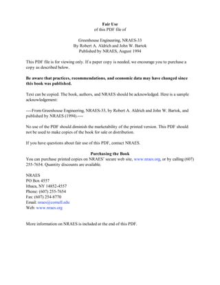
- 13. 7 DISADVANTAGES 1) Increased initial investment—Pumps, tanks, controls, and support systems increase costs by several dollars per square foot. If supplemental lighting or a growth room is included, a large additional cost will be incurred. 2) Higher energy costs—Pumps, lights, and additional controls will require additional energy. 3) More technical skills needed—A grower needs both a good plant science and chemistry background. CROPS Although almost any crop can be grown hydroponically, the most common are leaf lettuce, tomatoes, cucumbers, strawberries, watercress, celery, and some herbs. One key factor in system design for a particular crop is how it is supported in the nutrient solution. GROWING SYSTEMS During the past few years, many innovative systems have been developed to replace the traditional gravel-filled bed. When evaluating the type of system to install, consideration should be given to such factors as types of crops grown, space requirements, growing time, support system, and economics. Growing systems can be set up in either a greenhouse or a growth room. Some growers use both: the growth room for germination and seedling production, and the greenhouse for growing the crop to maturity. Extra heat from the growth room lights may be used to heat the greenhouse. Several soilless growing systems are shown in Figure 1–6. Sand/Stone Culture This technique for growing almost any type of plant consists of a deep bed (18–24 in.) of sand, pea stone, or trap rock placed in a plastic-lined trough or bed Figure 1–6. Soilless growing systems: a) Sand/Stone Culture; b) Pipe System; c) Tray System; d) Bed system with polystyrene flats for plant support; e) NFT System; and f) Bag System. f. Bag System Drip Tube Polyethylene bag Rockwool, Foam, or Peat-Vermiculite mix d. Bed system with polystyrene flats Polystyrene flat PVC Liner Nutrient Solution b. Pipe System Nutrient Supply Line 3" PVC pipe sloped to drain nutrients Chain Support and Conveyor System a. Sand/Stone Culture Concrete Bed and Aisle Sand or Stone Support Medium Polyethylene or Polyvinyl Liner c. Tray System Direction of Travel Track Nutrient SolutionShelf Growth Tape Slat Air Duct e. NFT System Nutrient Starter Block Polyethylene Channel This page is from Greenhouse Engineering, NRAES-33. To purchase the book, visit www.sare.org or www.nraes.org, or call (607) 255-7654. Page 1 of this PDF has fair use information.
- 14. 8 which slopes to one point to drain off excess nutrient solution (a minimum slope of 2% is recommended for most systems). Seedlings are set directly into this medium and watered several times per day with the nutrient solution. Troughs and Pipes Open and closed troughs are commonly used for lettuce, tomatoes, and cucumbers. Troughs and pipes may contain just the nutrient solution or may be filled with peat moss, vermiculite, or perlite. Some are mounted on rollers or movable racks for spacing the plants as they grow. PVC pipes (2–3 in. diameter) with holes 6 in. on center are being used for leaf lettuce production. Carts may be used to move pipes from the growing area to the packing room. Trays Periodically, flooded trays are used for growing lettuce. Plants grown in 1–2 in.2 growth blocks may be spaced manually as the plants grow. Trays are made from molded plastic, waterproof plywood, or flake board. Plastic is used as a liner. Beds Bed systems are composed of a plastic-lined ground bed with nutrient solution pumped in at one end and removed at the other. Lettuce plants are supported in foam polystyrene flats which float on the solution. Nutrient Film Technique (NFT) This system uses channels formed of thin plastic film which are placed on the floor and slope the length or width of the greenhouse. Nutrients are supplied to one end of the channel through plastic tubing and drain into a below-ground reservoir at the other end. Seedlings are usually grown in pots, poly bags, or growth blocks in the channel. Bags A modified hydroponic system uses polyethylene film bags, filled with a peat-vermiculite mix, foam, or rockwool placed end-to-end. Drip tubes or soaker hoses supply the nutrient solution. Aeroponics For this modified system, plants are supported through a plastic cover to a closed tank. Nutrients are supplied to the roots as a fine mist or fog. Other Components Besides the plant support system, tanks, pumps, and controls are needed. Tanks of concrete, plastic, or wood are common. Submersible pumps made for chemical solutions should be used because fertilizer salts corrode pumps made for use with water. Controls can be simple time clocks and manual switches or complex computers which automatically adjust the chemical content of the nutrient solution. Institutional Greenhouses Greenhouses for academic units, retirement homes, rehabilitation centers, or public parks and gardens have unique requirements. The objective of a commercial greenhouse operation is to realize a financial profit. Institutional greenhouses such as those in schools, retirement homes, rehabilitation centers, and public areas all have different objectives. School greenhouses teach basic knowledge and develop skills, while retirement home greenhouses provide an environment for relaxed enjoyment of growing plants. Rehabilitation centers use greenhouses as therapy to assist persons in living fulfilling lives. Public parks and gardens provide enjoyment and education for the general public. There may be highly structured programs carried out in school and rehabilitation center greenhouses but very little formal programming in a retirement home greenhouse. The institutional greenhouse can be of standard commercial construction unless there is a unique architectural need to satisfy aesthetics. Environmental control systems can be the same as those used in commercial greenhouses, although hot water heat can provide more accurate temperature control. The system should be automated to ensure acceptable control in the absence of personnel. Equipment, including benches, watering devices, lighting, etc., may require modification to fit particular situations. Equipment noise should be as low as possible. Additional doors may be needed to satisfy safety requirements because of occupancy. This page is from Greenhouse Engineering, NRAES-33. To purchase the book, visit www.sare.org or www.nraes.org, or call (607) 255-7654. Page 1 of this PDF has fair use information.
- 15. 9 Site selection should be based on the same factors considered for siting a commercial greenhouse. In some areas, the need for public access may require a site which is less than optimum for factors considered critical in commercial production. An example would be a public garden greenhouse having relatively inefficient materials handling facilities because of the need for public access and aesthetic considerations. Acceptable orientation for sun, protection from prevailing winds, and drainage are still very important in site selection, although wind breaks can be created. Functional layout of the institutional greenhouse will depend on the clientele to be served. For example, a high school program has different needs than a rehabilitation program. Convenient access is essential for all persons, including the handicapped, singly or in groups. The benches or floor growing areas should be arranged to permit several persons to have access without crowding. GREENHOUSES FOR TEACHING A greenhouse for teaching in elementary or secondary schools should be organized to provide experience through both individual and group projects. It should provide for student participation in all phases of plant production, from propagation to harvest of commercially important species and cultivars. Figure 1–7 shows suggested layouts for a secondary school teaching greenhouse. Figure 1–7. Suggested layouts for a secondary school teaching greenhouse. Wheelchair Access Ground Bed or Container Areas Sink A. In-line Layout Potting Mixing Storage Warm Section Cool Section 4' x 12' Benches 2' Aisles Work Table 20' 32' 32' 30' Chem. Storage Display Cooler Work Table B. T Layout Potting Chemicals 24' Classroom Demonstration Display Cooler Work Tables 32' 32'32' 70' 6' Ground Bed or Container Area Cool Section Warm Section Sliding Doors 4' x 12' Benches 2' Aisles This page is from Greenhouse Engineering, NRAES-33. To purchase the book, visit www.sare.org or www.nraes.org, or call (607) 255-7654. Page 1 of this PDF has fair use information.
- 16. 10 A separate but attached room should be used for such activities as medium mixing, seeding, pot or tray filling, transplanting, and some demonstrations. Containers, seeds, chemicals, equipment, and other supplies should be stored adjacent to the workroom and greenhouse. A small display cooler should be available in the workroom for storage of fresh plant material. A two-section greenhouse is desirable to provide separate warm and cool environments. The environmental control system should be automated to ensure acceptable conditions when the greenhouse is unattended. Distribution systems for heating and cooling should be arranged to permit changes in the operation to satisfy instructional needs. An alarm system should be installed to alert those responsible when environmental control equipment malfunctions. The electrical system should provide circuits for general lighting, special purpose lighting, special purpose heating, special equipment operation, and general cooling. All convenience outlets should be waterproof and mounted above bench height. The water distribution system should permit changes as instructional needs require. Suggested utility distribution systems are shown in Figure 1–8. Benches should be built to permit changes in layout or benching system. The use of rolling benches, trays, or pallets should be possible alternatives in the instruction program. Figure 1–8. Environmental control for teaching greenhouses. CROSS SECTION Perforated PE Tube General Lighting Duplex Outlet Sidewall Vent Finned Tube Valved outlet for root zone heating Hose Valve Aspirated box for Thermostat Bench Top PLAN Sidewall vents full length each section Duplex Outlet Valved outlet for root zone heating Container Area Hose Valve General LightingMotorized Louver Fan and perforated PE tube for mild weather cooling Finned tube space heating PartitionWall COOL SECTION WARM SECTION Exhaust fan Aspirated box for Thermostats Bench Area Valved outlet for root zone heating Classroom This page is from Greenhouse Engineering, NRAES-33. To purchase the book, visit www.sare.org or www.nraes.org, or call (607) 255-7654. Page 1 of this PDF has fair use information.
- 17. 11 RETIREMENT CENTER GREENHOUSE A retirement center greenhouse should provide convenient access for able-bodied persons and those confined to wheelchairs or assisted by walkers. Hard-surfaced, non-skid aisles are necessary, and benches should be at heights which accommodate persons both standing and sitting. The greenhouse should have ample open space to facilitate movement and promote fellowship among residents. Separate areas should be provided for storage of greenhouse supplies and for pot filling, transplanting, and other service activities. There should be a floor drain in the service area. Fan noise levels should be as low as possible, so belt-driven units should be used for ventilating. Separate cool and warm sections are desirable if conditions permit. Figure 1–9 shows possible layouts for retirement center greenhouses. Figure 1–9. Suggested layouts for retirement center greenhouses. B. Attached Gable Greenhouse 24' 32' 8' Access to living unit Access to outside Service Area Drain Storage 3' Aisle for Wheelchair 2' Aisles 4' Benches Fintube Heater A. Lean-to Greenhouse 10' 30' 16' 6' Access to outside Access to living unit Service Area Drain Work Bench Storage 3'Aisles 4'Benches Fintube Heater This page is from Greenhouse Engineering, NRAES-33. To purchase the book, visit www.sare.org or www.nraes.org, or call (607) 255-7654. Page 1 of this PDF has fair use information.
- 18. 12 REHABILITATION CENTER GREENHOUSES A rehabilitation center greenhouse should be arranged to accommodate a variety of programs. When designing space for use by the physically handicapped, consider space for wheelchairs, as well as the height of equipment and controls. Space arranged for wheelchair operation will also accommodate persons supported by crutches or braces. Figure 1–10 shows recommended dimensions for men and women operating from wheelchairs. Figure 1–10. Anthropometrics for wheelchair-bound men and women. Access walks to the greenhouse should be at least 48 in. wide, have a smooth surface, and a maximum grade of 5% (6 in. every 10 ft.). The greenhouse entrance should have a level platform on either side of the door. Dimensions are shown in Figure 1–11 on the opposite page. If space is so limited that a 5% grade would not provide the necessary elevation, a ramp with side rails must be installed. The surface should be non-slip and must have a maximum grade of 8.3% (10 in. every 10 ft.). Ramp length should not exceed 30 ft. between level platforms. Dimensions are shown in Figure 1–12 on the opposite page. Mean 5'¾" Anthropometrics: Wheelchair-bound men + = maximum reach – = minimum reach +4'9¼" mean 4'4½" head height –3'11¾" mean 3'5" shoulder +3'9¼" –3'¾" mean 2'3¼" elbow +2'6" –2'½" Eye level mean 4'¼" +4'4¾" –3'7¾" Mean forward reach 1'9¾" over high table 1'2" over low table –1'5¾" –8" mean 1'11¾" knee level +2'2½" +8½" Foot height Thigh level at point of obstruction Anthropometrics: Wheelchair-bound women + = maximum reach – = minimum reach +4'6¼" mean 4'1½" head height –3'8¼" mean 3'3" shoulder +3'7½" –2'10¾" +2'6" –2'½" mean 2'3¼" elbow Eye level mean 3'7½" +4'2" –3'5" 1'7" over high table 11½" over low table –1'3½" –5½" Thigh level at point of obstruction mean 1'11½" +2'2¼" +8¾" Foot height knee level mean 6½" Anthropometrics: Wheelchair-bound men + = maximum reach – = minimum reach mean 5'7½" vertical reach –5'2¼" Knuckle height mean 1'3" +1'4¼" +8¾" mean 7¼" Front edge of chair 1'7" mean 1'4½" +1'6½" +2'4¾" +2'1¾" mean 1'11½" 2'2½" Sitting erect Back Toe projection vertical reach Forward mean 4'7½" –4'3½" Oblique vertical reach mean 5'2¾" –4'10¼" Anthropometrics: Wheelchair-bound women + = maximum reach – = minimum reach mean 5'2" vertical reach –4'8¾" Oblique vertical reach mean 4'9¾" –4'5½" vertical reach Forward mean 4'3" –3'11" Toe projection +2'2" +1'11" mean 1'9" 2'0" Sitting erect Back mean 1'2½" +1'4½" Front edge of chair 1'7" +7" mean 5¾" Knuckle height mean 1'4½" +1'5½" This page is from Greenhouse Engineering, NRAES-33. To purchase the book, visit www.sare.org or www.nraes.org, or call (607) 255-7654. Page 1 of this PDF has fair use information.
- 19. 13 Figure 1–11. Suggested greenhouse layouts for handicapped persons. Figure 1–12. Ramps for handicapped access. B. 21' Greenhouse 58' 42' 16' 21' inside 5' x 5' Conc. Slab 8' 5' 8' A. 30' Greenhouse 8' 8' 5' 5' 4' 4'6" 4'6" 4' x 8' Benches 4' x 12' 4' x 12' 4' Aisle 42' 16' 58' 5' x 5' Conc. Slab 30' inside 2'8" 2" O.D. Met. Railings Slope not to exceed 1" vertical to 12" horizontal. ELEVATION PLAN 1/8" Met. Platform 2" x 4" Curb 2" x 4" slats 3/8" apart or Broomed Concrete Single run access ramp 2'5" 4" 4" 2" x 4" Curb ELEVATION Slope not to exceed 1" vertical to 12" horizontal. 2' 12" 4" PLAN 12'0" 6'0"6'0" 5'10" 2'5" Double run access ramp This page is from Greenhouse Engineering, NRAES-33. To purchase the book, visit www.sare.org or www.nraes.org, or call (607) 255-7654. Page 1 of this PDF has fair use information.
- 20. 14 Special identification should be used for sight- and hearing-impaired persons. Raised letters and numbers should be used for bench or table identification and should be placed on both ends of benches or on the ends next to the aisle. Place raised- letter signs 4.5–5.5 ft. high at the sides of doorways. All hazardous openings should be identified with knurled hardware, a change in flooring material, and audible signals. Visible signals should be placed as warnings for the hearing-impaired. The watering system should be installed so that the handicapped can easily operate it. Easy-to-operate water taps should be located at each bench. Lever- action fittings are preferred for people with limited hand function. Screw-type fittings should allow a firm grip. Provide a clearance of 1 in. between handles and any surface. Electrical switches should be placed for easy access by the handicapped person. Switches should have simple and positive action with no more than two switches together on one plate. Time clocks, thermostats, and other control devices should be conveniently placed. Adjustment knobs, etc., may require modification to permit the handicapped person to operate equipment easily. Bench supports should be placed back 6–12 in. from the outer edges to provide knee room for seated persons. Bench height should be from 30–36 in. for comfortable working. An adjustable height bench is shown in Figure 1–13. PUBLIC PARK OR GARDEN GREENHOUSE A public garden greenhouse or conservatory should be organized to display plants and/or plantings Figure 1–13. Adjustable height bench. Length to Fit 3 to 5 feet 2" x 4" on Edge 2" x 4" Flat for Pipe Flange 1" Dia. Galv. Steel Pipe 1" x 1" x 1" Split Tee 1¼" Dia. Steel Pipe 1¼" Pipe Flange 1¼" x 1¼" x 1" Split Tee ¼" Dia. x 2" Machine Bolt 5/6" Dia. Holes 1½" on Center 1" Dia. Galv. Steel Pipe 1" Pipe Flange Notes: 1. Legs spaced 4' O.C. maximum 2. Set legs on level half patio blocks on sand 3. Use pressure treated lumber for frame 4. Top can be welded wire, pressure treated lumber, redwood or cypress boards 5. Add sides for bench crops This page is from Greenhouse Engineering, NRAES-33. To purchase the book, visit www.sare.org or www.nraes.org, or call (607) 255-7654. Page 1 of this PDF has fair use information.
- 21. 15 to their best advantage. The interior should be open to promote creativity in arrangements and to provide control of visitor movement without undue restriction. Some efficiency in plant care may be sacrificed in order to develop pleasing displays. Clear heights of 30–40 ft. or more are needed in some areas to allow display of tall specimen plants or unique arrangements. Environmental control may be more difficult in public greenhouses because of periodical changes in plant arrangement. It may be necessary to move or modify equipment to maintain acceptable control. Water and electricity supply lines should be installed to permit alternative design arrangements without major reworking. A classroom or laboratory for lectures and demonstrations should be attached to the greenhouse. Adequate workroom space is necessary for preparing plant material, along with a storage area for general supplies. The workroom and storage area should be located where public access is discouraged or prevented. Special Purpose Facilities SHADE STRUCTURES Shade structures are used to provide minimal protection against wind and solar radiation for nursery crops such as shrubs and ground cover. They are also used in garden center retail sales areas. They provide from 60–80% shade, depending on slat size and spacing. Because they are permeable to wind, the structures may be framed somewhat lighter than a greenhouse; however, snow will bridge the slats, so the frames must be strong enough to carry expected snow loads. A typical shade structure is shown in Figure 1–14 on page 16. Shading can be used on greenhouses to reduce light and heat load on plants. Commercial shading compounds can be sprayed on the outer surface of a greenhouse. Such compounds gradually wear off as the summer advances, and any remainder is washed off in late summer or early fall. Manufacturer’s directions should be followed when applying such materials. Any shading compound still on the greenhouse surface in mid-September should be removed to ensure adequate light transmission. The following is a recipe for shade remover: Into one gallon of hot water, mix 4-1/2 lb. sodium carbonate (water softener) and 1 lb. trisodium phosphate (detergent); stir until it is dissolved. Add one gallon of 52% hydrofluoric acid and stir. Add the mixture to 23 gal. cold water and stir. Use a soft bristle brush to scrub the glazing. Rinse. Shade materials that will provide from 20–90% shade are also available. Most are made of polypropylene, polyethylene, or polyester. They can be supported internally from thermal blanket systems or secured to the exterior glazing surface. External shading fabrics must be secured to resist wind forces. OVERWINTERING STRUCTURES Overwintering structures are temporary structures used to provide protection from wind and temperature to container-grown nursery stock. They are generally framed with pipe or conduit (steel or aluminum) bent to form an arch and covered with white polyethylene film. A-frames of wood are also used, but inside space is somewhat restricted. Figures 1–15 and 1–16 on page 17 show typical structures. Most overwintering structures are kept with temperatures below freezing but above 25°F to prevent damage, which can result from excessive moisture loss due to wind or high temperature if the ground is dry or frozen. Irrigation may be necessary for some species to maintain quality. Plant containers are set against each other during overwintering and spaced apart in the spring; therefore, overwintering structures are separated to provide the needed summer growing area. Irrigation is generally provided by overhead sprinklers, but this practice wastes water and can produce pollution problems if fertilizer is applied through the watering system. Facilities should be available for accumulating orders to be shipped. Containers can be set on pallets to be picked up by a forklift or set on wagons to be transported to the loading area. See Chapter 3 for additional information on materials handling. COLD FRAMES AND HOTBEDS Cold frames are used to start or harden-off seedlings in the spring or extend the growing season in the This page is from Greenhouse Engineering, NRAES-33. To purchase the book, visit www.sare.org or www.nraes.org, or call (607) 255-7654. Page 1 of this PDF has fair use information.
- 22. 16 Figure 1–14. A permanent shade structure using prefabricated shade fence on a timber frame. The building is constructed in 12 ft. x 12 ft. modules. Shade Fence or Furring Strips2"x6" 2'-0" O.C. 2 - 2"x10" 12'-0" O.C. 2"x4" Braces Each Column 4"x4" Wine Braces Each Column 4"x4" Pressure Treated Columns 12" O.C. Each Direction 12'-0" 9'-0" 3'-6" Grade 2'-0" 2'-0" CROSS SECTION PLAN LAYOUT 12'-0" 12'-0" 2 2"x10" Beams 12'-0" O.C. 4"x4" Pressure Treated Posts 12'-0" O.C. Each Dir. 2"x6" Rafters 2'-0" O.C. Shade Fence This page is from Greenhouse Engineering, NRAES-33. To purchase the book, visit www.sare.org or www.nraes.org, or call (607) 255-7654. Page 1 of this PDF has fair use information.
- 23. 17 Figure 1–15. Typical overwintering hoop house of steel conduit or fence pipe. Figure 1–16. A-frame overwintering structure. 1" x 4" wind brace. Fasten wind brace and ridge board to hoops with U-bolts. Anchor timbers with steel pins 4' O.C. ELEVATION 1" x 4" Ridge board Hoops spaced 4' O.C. set in holes in timber Length of house to suit− generally 96' or 144' CROSS SECTION 12'0" Film Battens Film buried 6" x 6" Pressure Treated Timber 1" dia. steel conduit or fence pipe. Ends can be framed or plastic can be draped across ends. 6' radius White polyethylene film either buried or secured to timbers with battens. 1" x 4" Ridge Boards 1" x 6" Collar Tie 2" x 4" x 10' 6" x 6" Pressure Treated Timber Sill 4" x 4" Pressure Treated Sill Frame End View 3'0" DoorwaySecure 4"x4" to 6"x 6" with framing anchor 12'1" 13'0" Frame Side View 1" x 4" Wind Brace each side, each end of the buildinig Anchor sills with 3'0" steel stakes 6' O.C. Framing anchor to secure frame to sill Cover frame with 6 mil white polyethylene. Fasten to sill with 1" x 2" battens. 3'0" 3'0" Multiples of 3' This page is from Greenhouse Engineering, NRAES-33. To purchase the book, visit www.sare.org or www.nraes.org, or call (607) 255-7654. Page 1 of this PDF has fair use information.
- 24. 18 fall. Cold frames are heated only by the sun. If heated artificially, they are called hotbeds. Orient cold frames to the south and set them on well- drained soil. If possible, set them into the ground to take advantage of ground heat. Figure 1–17 shows typical cold frame construction. Construct the frame to permit tray or pallet handling of plants. Ventilation prevents temperatures from rising too high on sunny days. Although it is possible to automate the ventilation system, it may not be practical because of the short lengths of time cold frames are in use each year. Heat, if desired, can be supplied from electric cable, hot water, steam, or warm air. Supply 50–60 Btu/hr./ft.2 of ground area. REFRIGERATED STORAGE FOR GREENHOUSE AND NURSERY CROPS Refrigerated storage is necessary to maintain the quality of the harvested crop prior to use or marketing. Precooling and rooting rooms can extend the flowering period for forcers of spring flower bulbs. The recommended storage temperature is crop and use dependent, varying from 32°F for most cut flowers to 40°F and above for some bulbs. Relative humidity should be held above 90% for cut flowers and fresh vegetables, above 80% for nursery stock, and from 70–75% for bulbs. Appendix XI gives recommended storage conditions for several commodities. Figure 1–17. Cold frame construction system. 4'0" 4'0" 6'0" Pipe Rail Pipe can be used for warm water heat supply Trays rolled into cold frame from either end Rafter Top constructed in 8" units PLAN PIPE FRAME 4'0" 4'0" 6'0" PLAN Drop Front Rafter Pipe Rail Pipe can be used for warm water heat supply CONCRETE FRAME Cross Section a. Roll-up cover with drop front for fork lift loading 6'0" 6" Gravel 6" Sand Sill 2'0" 1'0" Hinge for drop front PE film roller pipe hand cranked Film rolled part way for ventilation Batten for film 6" Conc. or Concrete Masonry Wall 12" 6" 3'0" Tray Flats 2" x 4" Rafter 4'0" O.C. 1½" x 3" Butt hinge 4' O.C. 2" x 4" Plate Eye Bolt 18" O.C. 2" x 2" x 6' cover support bar Gate Hook Eye Bolt Screw Eye Eye Bolt Rafter b. Hinge cover with end loading of trays Section & Details 2" x 4" Top rail 3'0" 1'0" 6" Gravel 6" Sand Tray Flats 2" x 4" Rafter 2" x 4" Rail Pipe 1¼" Dia. Pipe 4' O .C. 2" Pressure Treated T&G Lumber This page is from Greenhouse Engineering, NRAES-33. To purchase the book, visit www.sare.org or www.nraes.org, or call (607) 255-7654. Page 1 of this PDF has fair use information.
- 25. 19 Water loss from stored material is reduced by lowering the product temperature and by maintaining a high relative humidity in the storage area. Water vapor is lost from the storage air through air exchange with the outside and by condensation on coils of refrigeration equipment. The minimum relative humidity in the storage is determined by the temperature difference between the evaporator inlet and outlet. Table 1–2 on page 20 shows the relationship between temperature drop and resulting relative humidity. It is important that the Figure 1–19. Layout for storage and rooting rooms for 100,000 bulb capacity. Figure 1–18. Packing room layout for cut flower operation. Example: 100,000 sq. ft. for rose house. refrigeration system be matched to the anticipated load so that relative humidity can be held at the desired level. Most retail outlets will use a walk-in cooler with glass doors so that customers can view materials. Coolers for wholesale cut flower producers should be large enough to store the harvest for at least two days. Placement of coolers with respect to harvest area and the packing room is important. Figure 1–18 shows a plan for a wholesale cut flower operation. Bulbs to be stored for periods of longer than three weeks should be placed in shallow, wire- bottomed trays that can be stacked in the cooler to permit adequate ventilation. The use of a rooting room extends the flower production period. Since temperature and time sequences vary depending on flower period, a compartmentalized rooting room with proper controls is desirable. Ventilation is necessary to maintain air quality, and water must be available for easy application. Provide enough artificial lighting for worker activity (20 foot-candles at plant levels), but exclude all natural light. Bulb storage and rooting rooms should be located and arranged for easy movement in and out of the facilities. Figure 1–19 shows a plan for a bulb forcing operation. Office 12' x 16' Cooler 16' x 16' 4' x 16' Grading and Packaging Personnel Area 8' x 8' M 8' x 8' W Sorting—3' x 16' To Market Deliveries Dry Storage Greenhouses48' ROOTING ROOM 20' x 24' ½ hp Refrigeration 4,320 cu. ft. ROOTING ROOM 20' x 24' ½ hp Refrigeration 4' Pallet 3' Aisle 6' Doorway 1' for air circulation 3' Aisle 6" for air circulation TRAY STORAGE 12' x 24' 1/3 hp Refrig. 2,592 cu. ft. WORKROOM 16' X 52' Media Storage Receiving/Inspection Dry Storage to market Order Assembly tray filling, potting to greenhouse This page is from Greenhouse Engineering, NRAES-33. To purchase the book, visit www.sare.org or www.nraes.org, or call (607) 255-7654. Page 1 of this PDF has fair use information.
- 26. Table 1–2. Minimum relative humidity levels developed at storage temperature and for temperature drop across the evaporator.(a) AIR TEMPERATURE DROP MINIMUM RELATIVE HUMIDITY AT ACROSS EVAPORATOR STORAGE TEMPERATURES (°F) 32°F 38°F 1 95.8 96.1 3 87.1 88.8 5 79.4 82.0 10 62.7 65.3 15 49.3 51.6 (a) From Bartsch, J.A. and G.D. Blanpied. 1990. Refrigeration and Controlled Atmosphere Storage for Horticultural Crops. NRAES–22. Natural Resource, Agriculture, and Engineering Service, Cornell University, Ithaca, NY. 20 This page is from Greenhouse Engineering, NRAES-33. To purchase the book, visit www.sare.org or www.nraes.org, or call (607) 255-7654. Page 1 of this PDF has fair use information.
- 27. 21 References Joiner, J.N. (Editor). 1981. Foliage Plant Production. Prentice-Hall, Inc.: Englewood Cliffs, NJ 07632. Langhans, R.W. 1983. Greenhouse Management. Halcyon Press of Ithaca: Ithaca, NY. Laurie, A., D.C. Kiplinger and K.E. Nelson. 1979. Commercial Flower Forcing. Florists Publishing Co., 310 S. Michigan Ave., Chicago, IL 60604. Nelson, P.V. 1991. Greenhouse Operation and Management. Reston Publishing Co., Inc.: Prentice Hall, Englewood Cliffs, NJ 07632. Special Purpose Facilities Bartsch, J.A. and G.D. Blanpied. 1990. Refrigeration and Controlled Atmosphere Storage for Horticultural Crops. NRAES–22. Natural Resource, Agriculture, and Engineering Service: Cornell Univ., Ithaca, NY. DeHertogh, A. 1985. Holland Bulb Forcer’s Guide. Third Edition. International Flower-Bulb Center: Hillagom, The Netherlands. Havis, I.R. and R.D. Fitzgerald. 1976. Winter Storage of Nursery Plants. Publ. 125. Univ. of Mass.: Amherst, MA. Huseby, K. 1973. A Tree Seedling Greenhouse: Design and Cost. USDA Forest Service: Missoula, MT. Hardenburg, R.E., A.E. Watada, and C.Y. Wang. 1986. The Commercial Storage of Fruits, Vegetables and Florist and Nursery Stocks. Agric. Handbook No. 66.: U. S. Dept. of Agric. McGuire, J.J. 1972. Growing Ornamental Plants in Containers: A Handbook for the Nurseryman. Bul. 197. Univ. of Rhode Island: Kingston, RI. Privetto, C.U. 1976. Greenhouse Design for the Handicapped. Paper No. 76-4004. Am. Soc. of Agric. Engr., St. Joseph, MI. Hydroponics Cooper, A. 1979. The ABC of NFT. ISBS, Inc., 2130 Pacific Ave., Forest Grove, OR 97166. Reikels, J.W. Hydroponics. Ontario Ministry of Agriculture & Food Fact Sheet Agolex 200/24. Edifice Sir John Carling Bldg., 930 Carling Ave., Ottawa, Ontario, Canada K1A 0C7. Rush, H.M. 1985. Hydroponic Food Production. Third Edition. Woodbridge Press Publ. Co., P.O. Box 6189, Santa Barbara, CA 93160. This page is from Greenhouse Engineering, NRAES-33. To purchase the book, visit www.sare.org or www.nraes.org, or call (607) 255-7654. Page 1 of this PDF has fair use information.
- 28. 22 Chapter 2: Greenhouse Structures (1) In many states, agricultural buildings are either exempt from the code requirements or are treated as special use structures. Introduction Many construction systems are being used successfully for greenhouses. Some may have advantages over others for particular applications, but there is no one best greenhouse. The structural design of a greenhouse must provide safety from wind, snow, or crop load damage while permitting maximum light transmission. Therefore, opaque framing members should be of minimum size while providing adequate strength to resist expected loads over the planned life of the greenhouse. Each U.S. state has a basic building code(1) that is designed to ensure public safety, health, and welfare insofar as they are affected by building construction. Local political subdivisions within each state may adopt basic building codes that are not in conflict with the state code. The code may set design loads and material specifications that may limit the construction options of the owner. Design loads and mechanical properties of materials are either prescribed within the code or in accepted engineering practice. The accepted engineering practice refers to such things as method of structural analysis, working stresses for particular materials, and load distribution characteristics. Buildings are designed for future performance based on past experience with an acceptable probability of success. Design Load Design loads include the weight of the structure (dead load), loads brought on because of building use (live loads), and loads from snow and wind. Dead load depends on the framing, glazing system, and the amount of permanent equipment carried by the frame. For example, a pipe frame greenhouse covered with double polyethylene (PE) will have a much lighter dead load than a lapped glass greenhouse. Heating and ventilating equipment, water lines, etc., may add dead weight to the frame. Live loads may be people working on the roof, hanging plants (if in place for less than 30 days), or other items carried by the frame for short periods of time. The National Greenhouse Manufacturers Association (NGMA) gives a method for estimating the minimum live load and recommends a maximum live load of 15 lb./ft.2 of ground area covered. Figure 2–1 on the following page shows how loads act on greenhouse frames. Greenhouses should be designed to resist an 80 mph wind from the direction that will produce the greatest wind load. The actual load depends on wind angle, greenhouse shape and size, and presence or absence of openings and wind breaks. Snow load is based on expected ground accumulation, roof slope, whether the greenhouses are individual or gutter-connected, and whether they are heated or unheated. The NGMA has used a minimum value of 15 lb./ft.2 of covered area for snow load. Even if snow loads for the area are greater, heat is usually provided to melt snow since the minimum greenhouse temperature is about 50°F. Figure 2–2 on page 24 shows water equivalents of very wet or dry snow. Table 2–1 on page 24 summarizes minimum design values for loads on greenhouses. In the design of greenhouse frames, use the combination of the loads from Table 2–1 that results in the most unfavorable effect on the structure. Table 2–1 is included to indicate minimum values only. Actual design values depend on greenhouse shape, construction material, location, and use. This page is from Greenhouse Engineering, NRAES-33. To purchase the book, visit www.sare.org or www.nraes.org, or call (607) 255-7654. Page 1 of this PDF has fair use information.
- 29. 23 Figure 2–1. Loads on greenhouse frames. A. Gravity loads act downward and include dead load (the weight of the greenhouse), live loads (the weight of suspended crops, equipiment, workers, etc.), and snow load. B. The length and direction of arrows indicate relative size of wind loads and how they act on greenhouses. GABLE GABLE Wind ARCH Dead, live, snow Dead, live Dead, live, snow Dead, live HOOP Dead, live, snow Dead, live ARCH Wind ½ ¼ ¼ 30' HOOP Wind ½ ¼ ¼ This page is from Greenhouse Engineering, NRAES-33. To purchase the book, visit www.sare.org or www.nraes.org, or call (607) 255-7654. Page 1 of this PDF has fair use information.
- 30. 24 An 80 mph wind can produce a pressure of 16 lb./ft.2 . An 80 mph wind striking a typical 28-ft. span pipe frame greenhouse can produce an uplift force of 220 lb./ft. of greenhouse length. Since the dead weight of the building is very small, there is little to counteract the wind. Anchorage to the ground must be secure enough to resist winds. Materials and Methods of Construction FOUNDATIONS The foundation is the link between the building and the ground. It must transfer gravity, uplift, and overturning loads, such as those from crop, snow, and wind, safely to the ground. If the primary greenhouse frame consists of members spaced greater than 4 ft. apart, pier foundations are adequate and may be less costly than a continuous wall. A curtain wall can be used to close the area between piers. If primary frame members are spaced four feet or less, a continuous masonry or poured concrete wall is best. The footing should be set below frost or to a minimum depth of 24 in. below ground surface. It should rest on level, undisturbed soil, not on fill. Individual pier footings should be sized to fit load and soil conditions. The pier can be of reinforced concrete, galvanized steel, treated wood, or concrete masonry. The wall between piers can be poured or precast concrete, masonry, or any moisture and decay resistant material. A continuous foundation Figure 2–2. The depths of wet or dry snow equal to one inch of rain—one inch of water produces a force of 5 lbs./ft.2 on a horizontal surface. Table 2–1. Minimum design loads for greenhouse main frames. (For more complete information and recommendations, consult references.) LOAD DESCRIPTION MINIMUM VALUE (lb/ft.2 ) Dead(a) Pipe frame, double PE 2 Truss frame, lapped glass 5 Hanging basket crops (in place more than 30 days) such as tomatoes or cucumbers 4 Live (b) 2 Snow (greenhouse continuously heated to 50°F) 15 Wind(c) (a) For special construction, equipment support, etc., use estimated weights. (b) Includes distributed weight of workers and assembly or repair materials or other short time loads. (c) Wind loads act perpendicularly on surfaces. All other loads act on areas equal to ground covered. 5 lb. per sq. ft. 3 inches of wet snow 5 inches of dry snow This page is from Greenhouse Engineering, NRAES-33. To purchase the book, visit www.sare.org or www.nraes.org, or call (607) 255-7654. Page 1 of this PDF has fair use information.
- 31. 25 wall should be set on a poured concrete footing. The wall can be concrete or masonry. A 6-in. wall is sufficient for building spans up to 24 ft. Use an 8-in. wall for wider building spans. Typical foundation construction details are shown in Figure 2–3 on the next page; pier footing dimensions are given in Table 2–2 below. Pipes driven into the ground do not have enough resistance to prevent uplift failures from high winds, so such methods should be used only for temporary structures to be used for less than one year. FLOORS A gravel floor with concrete traffic aisles will provide drainage and weed control. Porous concrete makes a very good floor surface for greenhouses because it allows water to pass through and avoids the puddles or standing water common to floors of regular concrete, sand, or gravel. Porous concrete is made from a uniformly graded aggregate and a cement water paste. The most satisfactory porous concrete mix contains one cubic yard (2,800 lbs.) of 3/8-inch diameter stone that is free of dust and uniform in size, 5.5 sacks of standard Portland cement, and 4.25 gal. of water per sack of cement. There is no sand in the mix, which is placed on a well-drained base of sand or gravel. A 4-in. thick floor will carry personnel and light vehicle traffic. The concrete should be moved as little as possible during placing and screeded to the final grade with no tamping, as tamping would consolidate the mix and close the pores. Use an overhead bucket, two- wheel buggy, or wheelbarrow to move concrete to the floor location. The surface is not trowel-finished. The final surface will be rough compared with regular concrete, but it is comfortable for walking and easily maneuverable for vehicles. When the floor has been screeded to the final level, cover it with a polyethylene film to keep evaporation loss to a minimum; allow the concrete to cure for at least one week before using the floor. Roll over the PE film with a lawn roller to produce a relatively smooth surface. The final product should have a load carrying capacity of about 600 lbs./in.2 of surface. Average Portland cement concrete (regular concrete) can carry about 2,500 lbs/in.2 of surface; therefore, the use of porous concrete should be restricted to areas where personnel or light vehicles such as garden or utility tractors operate. Porous concrete should not be used in soil mixing areas or where large quantities of small particles can fall onto the floor. Particles will clog the pores and prevent downward water movement. Table 2–2. Pier footing diameters for sandy loam soil.(a) GREENHOUSE SPAN (ft.) PIER SPACING (ft.) 4 6 8 10 12 15 PIER DIAMETER (in.) 20 6 9 12 12 12 15 24 9 9 12 12 15 15 28 9 12 12 15 15 18 32 9 12 12 15 15 18 36 9 12 15 15 18 (b) 40 12 12 15 15 18 (b) 46 12 15 15 18 18 (b) 60 12 18 18 18 (b) (b) (a) The average soil is assumed to have a bearing capacity of approximately 4,000 psf. (b) Requires special design. This page is from Greenhouse Engineering, NRAES-33. To purchase the book, visit www.sare.org or www.nraes.org, or call (607) 255-7654. Page 1 of this PDF has fair use information.
- 32. 26 Figure 2–3. Typical foundations for greenhouses. A. PIPE FOUNDATION Greenhouse frame fastened to sill with anchor Bolt sill to bearing plate Weld bearing plate to pipe Galvanized steel pipe Pressure treated skirt board 2" Foamed polystyrene board or equiv. in ground 12" 9" Dia. Poured concrete Below frost 24" min 12" B. CONCRETE PIER FOUNDATION Greenhouse frame Frame anchor 2" Foamed polystyrene board or equiv. in ground 12" 3/8" Dia. Steel reinf. rod Concrete pier Conc. footing Below frost 24" min 12" 8" min. C. CONCRETE MASONRY WALL ON POURED CONCRETE FOOTING Frame anchor 2" insulation board Two coats of hot bituminous material or Portland cement plaster Gravel backfill Drain tile around footing Greenhouse frame Bolt sill to conc. block foundation Top of block wall 12" above grade Below frost 24" min 16" Concrete footing 8" Note: All greenhouse footings should be below frost or 24" minimum depth. Consult local building codes if they apply. D. ALTERNATE POST FOUNDATIONS FOR PIPE FRAME GREENHOUSES Board insulation Coupling Pressure treated skirt board Drive to min. depth of 30" Post Grade Note: A driven post provides limited resistance to uplift. Post anchor Frame anchor Pressure treated wood post Poured concrete or 2" x 4" x 8" pressure treated lumber spiked to post. Board insulation Coupling Pressure treated skirt board 6" 1/4" steel plate or 2 1-1/2" x 1-1/2" x 1/8" steel angles welded to pipe This page is from Greenhouse Engineering, NRAES-33. To purchase the book, visit www.sare.org or www.nraes.org, or call (607) 255-7654. Page 1 of this PDF has fair use information.
- 33. 27 FRAME Materials Wood, steel, aluminum, and reinforced concrete have been used to build frames for greenhouses. Some frames use combinations of these materials. Wood must be painted to protect against decay and to improve light conditions within the buildings. Preservatives should be used to protect any wood in contact with soil against decay, but they must be free of chemicals that are toxic to plants or humans. Creosote and pentachlorophenol-treated wood should not be used in greenhouses. Chromated copper arsenate (CCA) and ammoniacal copper arsenate (ACA) are waterborne preservatives that are safe to use where plants are grown. Redwood or cypress heartwood has natural decay resistance but is becoming more difficult to obtain at prices competitive with other materials. Wood frames include post, beam, and rafter systems, posts and trusses, glued laminated arches, and rigid frames. Steel and aluminum are used for posts, beams, purlins, trusses, and arches. Frames may be entirely aluminum or steel or a combination of the two materials. Aluminum is comparatively maintenance free, as is hot dipped galvanized steel. White paint on either material will improve the light conditions in a greenhouse. Both materials must be protected from direct contact with the ground to prevent corrosion. The rate of heat loss through steel or aluminum is much higher than through wood, so metal frames may need special insulation. Composite materials are sometimes used, such as a trussed beam of wood and steel or a member made of glass fiber-reinforced plastic. The use of reinforced concrete is limited to foundations and low walls. The large size of available reinforced concrete framing members limits use in such elements as beams and arches. Structural Form The greenhouse with a straight sidewall and a gable roof is the most common shape and has advantages in framing and in space utilization. Post and beam, post and truss, and arches are used to form the gable structure. Some typical structures are shown in Figure 2–4 below. Figure 2–5 on the next page shows a jig and roller that can be used for bending pipe conduit to form arches. The part circle arch or quonset-type frame is easily formed from rolled sections of steel or aluminum or from glue-laminated wood. It makes better structural use of frame material than a gable building but, in some applications, there is unused space because of sidewall curvature. The gothic arch frame can be formed from metal sections or glue-laminated wood. With proper design, it can provide adequate sidewall height without loss of strength. Any of the forms can be used to build a single greenhouse or a large range of gutter-connected units. Detailed plans for greenhouse structures incorporate support systems for movable thermal blankets as a part of the frame. The support system contributes Figure 2–4. Some typical greenhouse frames. Arch Roof Gable Roof Hoop Gable Frame Trussed Roof This page is from Greenhouse Engineering, NRAES-33. To purchase the book, visit www.sare.org or www.nraes.org, or call (607) 255-7654. Page 1 of this PDF has fair use information.
- 34. 28 to the strength of the frame and may be installed if economically feasible. Structural Joints A structural frame is only as strong as its weakest joint. There must be adequate fasteners at sill, plate, and ridge to ensure a safe building. Fasteners must resist loads from any direction—a snow load acts downward, but a wind load can act in any direction. Sills should be bolted to the foundation and metal connectors used to secure the wall frame to the sill. Use metal connectors at the plate and ridge, also. Do not rely on nails for structural joints in wood. GUTTERS AND DOWNSPOUTS Most greenhouse gutters for multiple span structures are designed to provide a safe walkway for roof erection and maintenance. Some gutters also act as beams to transfer roof loads to columns. They are generally more than adequate for carrying rainwater and snow melt. The downspout should be sized first. Once the downspout is sized to adequately handle expected rainfall intensity, calculate the size of gutter and drain pipe needed to handle rainwater runoff. Figure 2–5. Jig and roller for bending conduit and pipe for greenhouse arches. 20' length 1" dia. thick wall conduit 2" x 4" x 6" long hardwood blocks secure to floor 7'0" radius 13'6" 6" 1'3" 1. Set up jig on wood floor 2. Make end bends with pipe bender 3. Use 3' length of steel rod or pipe to make final bend. A. JIG FOR MAKING CONDUIT ARCH B. ROLLER PIPE BENDER 36" 18" 6" 3"1/2" drill Weld 7" x 12.25 lb/ft steel channel 2" x 11" x 1/4" steel strap 3/4" Machine bolt 1-5/8" 3-3/4" 1. As set will bend 21' length of 3/4" Dia. steel pipe to form 14' wide frame. 2. Use pipe bender to form straight end sections. 3. Adjust center wheel for other frame spans. 4" Dia. x 1-3/4" wide steel caster wheel 3/4" bore This page is from Greenhouse Engineering, NRAES-33. To purchase the book, visit www.sare.org or www.nraes.org, or call (607) 255-7654. Page 1 of this PDF has fair use information.
- 35. 29 One rule of thumb for sizing downspouts and gutters is 1 in.2 of downspout cross section for each 100 ft.2 of covered area to be drained, and a gutter diameter 1.5 in. larger than the downspout diameter. These sizes should safely handle a rainfall intensity of 3 in./hr. The duration of a storm of that intensity will vary with return period and location. For example, at Hartford, CT, an 11-minute storm expected to be experienced once in 2 yrs. (a return period of 2 yrs.) would have an intensity of 3 in./hr. A 26-minute storm in Hartford with a return period of 10 yrs. would also have an intensity of 3 in./hr. In St. Louis, MO, a 22-minute storm with a 2 yr. return period, or a 40-minute storm with a 10 yr. return period, would have an intensity of 3 in./hr. A 1-in. rainstorm on a 1-acre greenhouse will produce 1 acre-in. of water (3,630 ft.3 or 27,154 gal. water). As much as 95% of the water will run off the roof (the rest will evaporate) and must be disposed of in a safe manner. If irrigation water is expensive, it may be worthwhile to collect rainwater in a storage tank or small pond. The drain pipe size needed to carry rainwater away from the greenhouse depends on the area drained, the slope of the pipe, and the pipe material. Figure 2–6 on the next page gives the carrying capacities for smooth PVC and corrugated PE drain pipe. Gutters can be level but usually have a slope of 8 in./100 ft. or less. Within the greenhouse, the drain pipe should slope from 8–12 in./100 ft. Outside the greenhouse a steeper slope can be used, depending on the topography. Drain pipes are seldom laid on slopes greater than 3 ft./100 ft. (0.03 ft./ft.). The following example greenhouse, which will be referred to throughout the book, is 96 ft. x 192 ft., with a ground area of 18,432 ft2 . Each gable roof spans 24 ft., so each gutter serves a ground area of 4,608 ft2 . Using the rule above, the downspouts should have a cross sectional area of 23 in.2 (a circular section with a 5.5-in. diameter) if located at each end. The gutter should be a semi-circle with a 7-in. diameter or any other shape with a cross sectional area of 19 in.2 . Another option would be to have four downspouts, each serving 1,152 ft.2 . The downspouts would then have an area of 11.5 in.2 (a 4-in. diameter). The gutter would be a semi-circle with a 5.5-in. diameter or a 12 in.2 cross sectional area. If downspouts are placed at the ends of the gutter, they can be connected to a buried drain line along each gable wall. If this pipe runs the length of the greenhouse, it will have to be large enough to carry the rainwater from one-half the surface area (48 ft. x 192 ft. = 9,216 ft.2 ). A PVC pipe installed at a slope of 8 in./100 ft. would need an 8-in. diameter. A 10-in. diameter pipe would be needed to carry the water away from the total greenhouse area. COVERING Materials The light transmittance of greenhouse glazing materials should be considered when selecting the covering material. Figures 2–7 and 2–8 on page 31 show the spectral transmittance of several rigid and film glazing materials. The solar spectrum is included for comparison. Glass is still a common glazing material, and use of large panes has reduced the shading from glazing bars. Panes 30" x 36" are in use; Dutch houses have panes extending from valley to ridge. Dutch houses have the advantages of few parts and easy construction. Large panes, bar caps, and strip caulking have reduced labor required for installation. Three plastic film materials are in use as greenhouse covers. Polyethylene (PE) film has been used in large quantities for several years. It has high light transmittance, except in the ultraviolet region of the spectrum, and is transparent to infrared or long wave radiation. Its chief disadvantage is its lack of durability—it will last about nine months if put on in October, but may not last until the fall if put on in the spring. There are ultraviolet-inhibited (UVI or weatherable) PEs that will last longer, but in general they will fail after less than 18 months of exposure. Copolymer films will last two to four years. Infrared transparency can result in significant radiation cooling if there is no condensation on the film. The latest PE film introduced is infrared-blocking and, thus, has a lower rate of heat loss to clear skies. The majority of greenhouses constructed recently have used copolymer films. Some plastics have a wetting agent that keeps moisture droplets from forming. This page is from Greenhouse Engineering, NRAES-33. To purchase the book, visit www.sare.org or www.nraes.org, or call (607) 255-7654. Page 1 of this PDF has fair use information.
- 36. 30 Figure 2–6. Sizing drain pipe for rainwater and snow melt removal. Flowrate(gpm) 10,000 9,000 8,000 7,000 6,000 5,000 4,000 3,000 2,500 2,000 1,000 1,500 900 800 700 600 500 400 300 200 150 100 60 80 40 30 20 10 0.001 1.25 0.002 2.5 0.004 3.5 0.005 6 0.007 8 0.01 12 0.02 24 0.03 36 Slope (ft./ft.) Slope (in./100 ft.) Greenhousegroundarea(sq.ft.) Total greenhouse area 1/2 greenhouse area PVC Corrugated PE 320,820 288,940 256,655 224,575 192,495 160,410 128,330 96,246 80,250 64,165 32,080 48,125 28,875 25,665 22,460 19,250 16,040 12,830 9,625 6,415 4,810 3,210 1,925 2,565 1,280 960 This page is from Greenhouse Engineering, NRAES-33. To purchase the book, visit www.sare.org or www.nraes.org, or call (607) 255-7654. Page 1 of this PDF has fair use information.
- 37. 31 Figure 2–8. Spectral transmittance of selected film greenhouse covering materials. ULTRAVIOLET GLASS SUN'S RADIATION FIBERGLASS RIGID P.V.C. ACRYLIC POLYCARBONATE WAVELENGTH, NANOMETERS (NM) RELATIVEENERGY VIOLET 100 90 80 70 60 50 40 30 20 10 0 300 350 400 450 500 550 600 650 700 750 800 BLUE GREEN YEL. ORAN. RED Figure 2–7. Spectral transmittance of selected rigid greenhouse covering materials. POLYVINYL100 90 80 70 60 50 40 30 20 10 0 ULTRAVIOLET VIOLET BLUE GREEN YEL. ORAN. RED POLYETHYLENE POLYVINYL FLUORIDE U.V. POLYETHYLENE RELATIVEENERGY WAVELENGTH, NANOMETERS (NM) 800700600400300 350 450 500 550 650 750 This page is from Greenhouse Engineering, NRAES-33. To purchase the book, visit www.sare.org or www.nraes.org, or call (607) 255-7654. Page 1 of this PDF has fair use information.
- 38. 32 PE film is available in thicknesses of 1–8 mil. (1 mil. = 0.001 in.) and in widths up to 50 ft. folded or 16 ft. unfolded. For a double layer application, use 4 mil. PE on the inside and 4 or 6 mil. PE on the outside. Use 6 mil. for single layer applications. Use only unfolded PE if possible because film will fail first at the folds. It may be desirable to replace PE film annually on greenhouses where high light-requiring plants are grown. Polyvinyl chloride (PVC) is available as a film or as a rigid panel. Present PVC films will last more than two years if carefully applied. PVC with an ultraviolet inhibitor has lasted up to four years. One disadvantage of PVC film is the difficulty in keeping it clean to maintain light transmittance. The static electricity developed tends to attract dust. It is available in 4–8 mil. thicknesses and in widths of 36–72 in. The narrow width of vinyl film is a disadvantage in covering large areas. Rigid panels of PVC are inexpensive, easy to apply, and, when new, have high light transmissivity. Their light stability is affected by heat build-up in the panel. If they are carefully applied and partially shaded during hot weather to prevent heat build-up, they will provide good service. They are available in 24–36 in. widths and in lengths up to 24 ft. Fiberglass-reinforced plastic (FRP) panels have been used for years. They have transmissivities equal to glass and are easy to apply. Problems with surface erosion and discoloration, with resulting loss in light transmission, have limited their use in areas of low winter light. They are available in 24–57 in. widths and in lengths limited only by transportation. Structural panels of double wall glass or plastic are available for energy conservation. Double wall “thermal insulating” glass panels have not been used to any great extent in greenhouse construction because of cost and the difficulty of sealing panels. Extruded structural panels of acrylic and polycarbonate are being used for greenhouse glazing. They are available in widths to 96 in. for some products and lengths to 39 ft. Because of thermal expansion, these panels require special framing details to maintain edge seals. Some suppliers have specific architectural extrusions for mounting panels. The second layer of glazing reduces heat loss from the greenhouse and also reduces light transmission into the greenhouse. Each layer will reduce light transmission by about 10%. Table 2–3 on pages 33–34 gives general characteristics and price ranges for the more commonly used glazing materials. Application Systems Rigid plastic panels are easily applied to any conventional gable frame with the addition of horizontal supports (purlins) across the top of the glazing bars. Less framing is required for a fiberglass or double wall plastic panel covering than for glass because the panels are much stronger in bending than glass. The panels should be held away from purlins to prevent condensate drip. Follow the manufacturer’s directions for best results. Typical glazing systems are shown in Figure 2–9. Figure 2–9. Typical glazing systems for greenhouses. Bar Cap Glass Pane Caulk Sealant Roof Bar Roof Bar to Purlin Bolt Condensate Gutter Typical Glass Glazing on Aluminum Roof Bar Corrugated Polycarbonate Glazing Spacer Tek Screw or Ring Nail Purlin Fiberglass or Polycarbonate Glazing on Wood Purin Top Film (double sheet) Lock ring in place Outside of frame Hex head bolt & nut Base- board Acrylic or Polycarbonate Structured Sheet Two Piece Aluminum Extrusion Connector Support Frame Structured Sheet Glazing System This page is from Greenhouse Engineering, NRAES-33. To purchase the book, visit www.sare.org or www.nraes.org, or call (607) 255-7654. Page 1 of this PDF has fair use information.
- 39. 33 Table 2–3. Transmittance of solar and thermal radiation through greenhouse glazing material. (a) GENERAL TYPE COMMENTS TYPICAL TRADE NAMES LIGHT (PAR) TRANSMIT- TANCE (%) THERMAL TRANSMIT- TANCE (%) ESTIMATED LIFETIME (YEARS) $/FT.2 (b) GLASS Advantages Excellent transmittance Superior resistance to heat, U.V., abrasion Low thermal expansion- contraction Readily available Transparent Disadvantages Low impact resistance unless tempered High cost Heavy Double strength Insulated units Solatex 88 75–80 91–94 3 < 3 < 3 25+ 25+ 25+ 0.75–2.00 3.50–7.00 1.25–3.50 ACRYLIC Advantages Excellent transmittance Superior U.V. & weather resistance Will not yellow Lightweight Easy to fabricate on site Disadvantages Easily scratched High expansion- contraction Slight embrittlement with age High cost Relatively low service temperatures Flammability Single wall Plexiglass Double wall Exolite 93 87 < 5 < 3 20+ 20+ 1.50–2.00 2.00–3.50 POLYCARBONATE Advantages Excellent service temperatures High impact resistance Low flammability Disadvantages Scratches easily High expansion- contraction Single Wall Dynaglas Lexan Corrugated Macrolux Corrugated Double wall Macrolux PolyGal Lexan Dripgard 91–94 83 < 3 23 10–15 10–15 1.25–1.50 1.75–2.50 (a) Solar radiation wavelength from 0.38–2.5 microns. Thermal radiation at approximately 10 microns, the wavelength at maximum radiation from surfaces at 70°F. Data are for thicknesses used for greenhouse glazing. (b) Includes support extrusions and attachments but not installation labor. Adapted from manufacturers' data. Local prices may differ. No endorsement is implied where trade names are given. This page is from Greenhouse Engineering, NRAES-33. To purchase the book, visit www.sare.org or www.nraes.org, or call (607) 255-7654. Page 1 of this PDF has fair use information.
- 40. 34 GENERAL TYPE COMMENTS TYPICAL TRADE NAMES LIGHT (PAR) TRANSMIT- TANCE (%) THERMAL TRANSMIT- TANCE (%) ESTIMATED LIFETIME (YEARS) $/FT.2 (a) FIBERGLASS REINFORCED POLYESTER Advantages Low cost Strong Easy to fabricate and install Disadvantages Susceptible to U.V., dust, and pollution degradation High flammability Lascolite Excelite Filon Double wall roof panels 90 60–80 < 3 10–15 7–12 0.85–1.25 5.00 POLYETHYLENE FILM (PE) Advantages Inexpensive Easy to install Readily available in large sheets Disadvantages Short life Low service temperature Tufflite III 603 Standard UV Tufflite Dripless 703 Fog Bloc Sun Saver Cloud 9 Tufflite Infrared Dura- Therm < 85 50 50 < 20 3 3 3 0.06 0.07 0.09 POLYVINYL CHLORIDE (PVC) CORRUGATED Advantages Durable Good fire rating High impact strength IR inhibitor Disadvantages Lower light High expansion Yellows with age Only 4 ft. widths Bio 2 84 < 25 10+ 1.00–1.25 (Table 2–3 continued) * All plastics described will burn, so fire safety should be emphasized in greenhouses covered with such materials. (a) Includes support extrusions and attachments but not installation labor. transmittance available This page is from Greenhouse Engineering, NRAES-33. To purchase the book, visit www.sare.org or www.nraes.org, or call (607) 255-7654. Page 1 of this PDF has fair use information.
- 41. 35 The load carrying capacity of fiberglass or double wall plastic panels can be increased by applying them to a curved roof frame such as a quonset or gothic arch. This allows arch or shell action to contribute to the strength of the system. Correct design as an arch or shell will permit safe construction with a minimum of frame. There have been many systems developed to apply and fasten single and double layers of film plastics. Rafter lengths that fit available widths of layflat or unfolded film should result in fewer problems during the life of the film. Batten strips can be used with wood rafters or arches. Covered cables or wire can be used with pipe or extruded metal frames. Fans used to pull a partial vacuum or create positive pressure in the house can be used to reduce “flapping” from wind. Figure 2–10 shows the use of a front end loader or fork lift for placing polyethylene film on greenhouses. Double layers of film reduce conductive heat loss and condensate on the inside surface. Double battens can be used to apply two layers to the outside of a frame. The second layer can also be applied to the inside of the frame, but this is generally more difficult and, if applied to the ceiling, may negate insurance coverage. The air supported “bubble” house has been used generally as a temporary structure. It has advantages of low cost and fast erection, but problems with openings, warm weather ventilation, and possible power loss have prevented it from becoming a permanent greenhouse. A more popular system is the two-layer air inflation method, a combination of structural frame and film that results in a double film cover with the air gap exceeding four inches in some areas. This is the maximum gap suggested for heat flow control, but the ease of application and stability of the resulting structure more than offset the slight increase in heat loss. The system is illustrated in Figure 2–11 on the next page. The equipment needed to inflate and separate the film layers using this method includes a squirrel cage blower with a capacity of 100–150 ft.3 /min. at 0.5 in. of water column pressure, a damper to adjust blower pressure, and flexible tubes to transfer air between building sections. Blowers with lower Figure 2–10. Polyethylene film roll handling device for roof application. Safety chain Fork Mounting Wood bearing blocks Length to fit polyethylene steel pipe Welded steel channel frame Bolt to bucket Bucket Mounting This page is from Greenhouse Engineering, NRAES-33. To purchase the book, visit www.sare.org or www.nraes.org, or call (607) 255-7654. Page 1 of this PDF has fair use information.
- 42. 36 volume output can be used but do not have the capacity to keep the plastic inflated when holes develop. A damper is needed on the blower intake to adjust the inflation pressure. This can be a 4-in. diameter electric box cover or piece of sheet metal. A piece of 4-in. dryer-vent tubing is used to connect the blower exhaust to the plastic. An adapter made from a piece of wood may be needed on the blower. Support plates with dimensions of 6-in.2 and a 4-in. diameter hole in the center are cut from 3/8-inch plywood and used to attach the duct to the plastic. The plastic is sandwiched between two of these plates. Screws or stove bolts hold the plates together. Fire safety is important in the planning and operation of any facility, and becomes even more important if plastic glazing materials are used. All organic plastics will burn, some at a much faster rate than others. Three properties are generally used to rate the fire potential of materials: flame spread, burning rate, and smoke generation. Standard tests which determine these characteristics have been developed by Underwriters Laboratories (UL) and the American Society for Testing and Materials (ASTM). When comparing materials with respect to fire safety, it is important to know whether the same testing procedure was used for each. For example, ASTM Test No. D-635 tests for burning rate, and both ASTM E-162 and E-84 test for flame spread. UL-94HB tests for horizontal burn, and ASTM E-662 for smoke generation. Building codes specify those tests considered to provide most useful results. One state building code lists ASTM E-84 as the standard for determining surface burning characteristics of building materials; therefore, to satisfy that code, the material in question must have been tested by an independent laboratory and the results made available to the public. Figure 2–11. Details of an air-inflated polyethylene-covered greenhouse. Polyethylene Plastic Flower Pot Clothes Dryer Duct Fan Installation Squirrel Cage fan draws in outside airInstall adjustable damper to control maximum air pressure between film layers Polyethylene Fastening Grade Frame Member Post Skirt Plank Double Layer Polyethylene 1 x 2 6d nails every 12" This page is from Greenhouse Engineering, NRAES-33. To purchase the book, visit www.sare.org or www.nraes.org, or call (607) 255-7654. Page 1 of this PDF has fair use information.
- 43. 37 Construction Costs Greenhouse construction costs vary considerably, and cost comparisons should not be made unless detailed knowledge of services and materials provided is available. Comparing the costs of a glass glazed house with that of a PE film house is of no value unless all the specifications for each house are compared and related to the intended use of the greenhouse. Costs are often quoted on the basis of dollars per square foot of covered area. Cost per square foot of bench or bed area might be more useful, since it would reflect more closely the production potential of the house. Comparisons on the basis of net growing area will also emphasize bench arrangement for maximum use of enclosed space. The type of structure that should be purchased depends on factors such as the crops to be grown, the length of service the grower desires for the structure, the seasons the greenhouse will be used, and the amount of growing space needed. The grower should also consider economic factors such as interest, tax rates, and maintenance costs. Environmental control systems cost about the same for all types of structures. The systems described herein are automatic and have remote sensing devices, with values based on an average installation. Table 2–4 on the next page gives a brief summary of construction costs, including costs for environmental control. Reference NMGA. 1981. Greenhouse Design Standards. National Greenhouse Manufacturers Association. This page is from Greenhouse Engineering, NRAES-33. To purchase the book, visit www.sare.org or www.nraes.org, or call (607) 255-7654. Page 1 of this PDF has fair use information.
- 44. 38 CONSTRUCTION COSTS Materials $/ft.2 Erection Labor Cost $/ft.2 Total $/ft.2 Conventional Glass Greenhouse Concrete foundation—galvanized frame—truss roof 7.00–9.00 3.00–4.00 10.00–13.00 Ridge & Furrow Greenhouse Concrete piers—galvanized steel frame— double poly covering 2.50–4.50 1.50–2.00 4.00–6.50 Steel Pipe Arch Greenhouse Pipe foundation—1¼" galvanized pipe—polycarbonate structured sheet glazing 4.50–6.50 0.70–0.90 5.20–7.40 Steel Pipe Arch Greenhouse Poly cover—pipe foundation— 1¼" galvanized pipe 1.50–2.50 0.50–0.70 2.00–3.20 Rigid Frame Wood Greenhouse Poly cover—wood post foundation— clear span 1.00–1.50 0.50–0.75 1.50–2.25 (Site preparation will cost $0.75–1.00/ft.2 ;driveway and parking area, $0.35–1.00/ft.2 ; 3" concrete floor, $1.00–1.25/ft.2 ; and benches, $1.50–$4.50/ft.2 of floor area.) ENVIRONMENTAL CONTROL ($/ft.2 of Greenhouse Floor Area, including labor) Ventilation Fans with shutter, thermostat, and housing 0.95–1.35 Heating Oil- or gas-fired hot air Oil- or gas-fired steam or hot water 1.00–1.75 1.50–2.50 Electric Supply; materials and labor 1.00–1.50 Water Materials and labor 0.75–1.25 Heat Retention System Manual Motorized 0.50–1.00 1.25–3.00 Fog System 0.50–1.00 Environmental Control Computer 0.75–1.25 (a) 1994 prices; accurate cost estimates are possible only if a detailed plan of the greenhouse is available. Table 2–4. Greenhouse construction costs. (a) This page is from Greenhouse Engineering, NRAES-33. To purchase the book, visit www.sare.org or www.nraes.org, or call (607) 255-7654. Page 1 of this PDF has fair use information.
- 45. 39 Chapter 3: Materials Handling Introduction The production of most greenhouse crops is highly labor intensive. For example, in a bedding plant production system, the medium and containers used to grow plants may be handled a dozen times from initial delivery to drop off at the garden center. In a recent survey, bedding plant growers attributed approximately 25% of plant production costs to labor. The use of labor and equipment for greenhouse production must be examined as part of a system rather than as unrelated elements. Each task, whether performed by hand or by machine, is related to other tasks in the growing process. Operation size, container type, production schedule, available capital, and other factors enter into materials handling decisions. Mechanization in the greenhouse industry has developed slowly due to a lack of standard growing methods, variability of the physical arrangement of growing facilities, and the large varieties of crops grown. Several companies produce a wide range of equipment that can increase the efficiency of greenhouse operations by applying basic industrial principles. This chapter will review some of these principles and indicate how to best use such equipment. Operations Analysis Operations analysis is a technique for studying a system which utilizes simple diagrams, charts, and plans to identify components and relationships for proposing changes for improvement. An operation process chart shows subject, type, and method. “Subject” is the operation or system being studied; Figure 3–1. An operation process chart for the transplanting of a bedding plant production system (adapted from Ross, D.S., et al., 1974). Transport Operation Relay Inspection Storage Market flats from storage Seed flats from germination Move flats convenient to transplanter Transplanter sets flat on transplant table Level media in flat Move seed flats to transplant area Transplanter takes seedlings from seed flat Inspect for size and quality Transplant seedlings Flats are set on conveyor Waterer Seed flats and waste removed Flats by conveyor to stacker Flats stacked on pallets Pallets moved to greenhouse Flats unloaded from pallet Flats moved across greenhouse Flats placed on ground to growing Operation Chart Symbols This page is from Greenhouse Engineering, NRAES-33. To purchase the book, visit www.sare.org or www.nraes.org, or call (607) 255-7654. Page 1 of this PDF has fair use information.
- 46. 4041 “type” refers to material, person, or machine; and “method” tells whether the present, proposed, or revised system is being shown. An example of an operation process chart for the transplanting phase of a bedding plant operation is shown in Figure 3–1 on page 39. When using an operation process chart, consider the following questions: 1) Can events be combined? 2) Can inspections be eliminated? and 3) Can delays be eliminated or converted to storages? A flow process chart is used to study an operation in detail, so each step is listed regardless of its importance. Information on direction, distance traveled, and method of movement may be used for determining materials handling options. Unit times may be useful data if individual items, such as pots and plants for transplanting, are being processed. Total times, such as greenhouse growing time for different cultivars or species, may be important. Data gathered should include labor, machine and space use, utilities, grade factors, environment, and any other information that will contribute to understanding and improving the operation. Figure 3–2 shows another form of flow diagram used to indicate equipment needs. A plan layout is used to show either an existing system or one rearranged for improved operation. It should show the site with orientation, wind direction, service roads and utilities, and a floor plan with walls, columns, etc. Figure 3–3 on page 41 shows a plan layout for a bedding plant facility. Plan layouts should be developed based on the following: 1) Material from one operation should be placed where it can be picked up easily for the next operation; 2) The distance an operator must move to obtain or deliver material should be kept to a minimum; and 3) Time spent by a machine performing an operation which does not require the operator’s immediate attention is idle time for the operator and should be put to other use. The greenhouse plant production rate depends on efficient use of labor, work and storage space, transportation, and all other facilities that contribute to the operation. In a well-planned range, all Figure 3–2. Flow diagram—soil mix preparation. SOIL (bulk) PEAT (bags) VERMICULITE (bags) Bucket loader SHREDDING Shredder w/ screen PASTURIZATION Chemical Bucket loader Bucket loader BATCH MIXING 2 yd. Ribbon Mixer STORAGE (bulk) POT FILLING Belt Conveyor Conveyor & Feeder Bin Scale LIME FERTILIZER Bucket loader Bucket loader This page is from Greenhouse Engineering, NRAES-33. To purchase the book, visit www.sare.org or www.nraes.org, or call (607) 255-7654. Page 1 of this PDF has fair use information.