SlideShare uma empresa Scribd logo
1 de 18
Baixar para ler offline
1
Redevelopment of the Proctor Hydroelectric Station
A Technical Paper for HydroVision 2016
Authors
Heather Martin, P.E. – Project Engineer, Kleinschmidt Associates, Maine, United States
Adam Haskell, P.E. – Project Manager, Kleinschmidt Associates, Maine, United States
Michael Scarzello – Generation Asset Manager, Green Mountain Power Company, Vermont,
United States
Abstract
After purchasing the Proctor Hydroelectric Station in Proctor, Vermont, in 2011, Green
Mountain Power (GMP) undertook a multi-year, phased approach to redevelop nearly all
components of the station. Upgrades included reconfiguring and streamlining the intake;
replacing a 9-foot-diameter penstock; removing two surge tanks; replacing three vertical turbines
installed in 1905 with new, vertical-axis, Francis units; rewinding and restoring the generator of
a vertical Francis unit installed in 1926; replacing electrical power and control systems;
constructing an access bridge to the power station; and other modifications to improve
generation, operation, and safety of the station. Since completion of the project in 2015, the
station’s generation capacity has increased from 3 megawatts (MW) to more than 10.23 MW,
and it is now the largest of GMP’s 32 hydroelectric generating facilities. This paper describes the
redevelopment of an historic, deteriorated, and nearly obsolete project into a modern, reliable,
and safe facility and discusses the challenges encountered during the design, permitting, and
construction phases of the project.
Introduction
The Proctor Development is an historic hydroelectric power station on the Otter Creek in
Proctor, Vermont. Proctor is owned and operated by Green Mountain Power (GMP) as part of
the Otter Creek Hydroelectric Project license. Before GMP purchased Proctor, only one of five
turbine-generator units was functional, and much of the station’s infrastructure and equipment
needed repair or modernization. Beginning in 2011, GMP implemented a strategic plan to
modernize and redevelop nearly all components of the station to increase generation, reliability,
and overall safety of the development.
The Vermont Marble Company built the Proctor hydroelectric power station in 1905 to supply
electricity to its marble factory. Some of the most well-known uses of The Vermont Marble
Company’s product include the Tomb of the Unknown Soldier and tombstones for Arlington
Cemetery in Washington, D.C. The original hydro station, shown in Figure 1, contained three
750-kilowatt (kW), vertical Francis, I.P. Morris units (Units 2, 3 and 4) and one 1,680-kW,
2
vertical Francis, S. Morgan Smith unit added in 1926 (Unit 1). The power station superstructure
is constructed of marble blocks with a timber roof and a marble aggregate concrete substructure.
Water was supplied to the units by one 9-foot-diameter, riveted-steel penstock connected to a
concrete intake structure located adjacent to a 13-foot-high masonry dam at the top of the
adjacent falls. The total installed capacity was 3.9 MW.
Figure 1 Original Proctor Hydroelectric Station (Photo Credit: Vermont Marble
Archives, Date Unknown)
In 1984, The Vermont Marble Company added a 3-MW, vertical Francis, Boving turbine
(Unit 5) to the station to generate electricity from additional available flows. To accommodate
Unit 5, Vermont Marble expanded the powerhouse, added a new 7-foot-diameter steel penstock
and surge tank, and modified the intake. The new unit increased Proctor’s total installed capacity
to 6.9 MW.
3
In 2011, Central Vermont Public Service (CVPS) purchased Proctor from Vermont Marble and
identified the station’s redevelopment potential. At that time, only Unit 5 was in operation; the
four other units had been dormant for several years due to concerns about electrical safety and
mechanical issues. GMP purchased CVPS and its generating assets in 2011. This paper describes
the multi-year redevelopment and discusses challenges encountered and overcome throughout
permitting, design, and construction.
Phases of the Redevelopment
GMP took a comprehensive approach to the redevelopment project with goals to modernize the
components of the station, extend its service life, and limit future maintenance. Careful planning
to approach these comprehensive goals optimally was a major part of making this project
successful. Kleinschmidt helped GMP divide the project into phases that are shown on a timeline
in Figure 2, and in before and after aerial photographs in Figure 3. The phases allowed for the
time necessary to obtain approval from the Federal Energy Regulatory Commission (FERC) and
permitting agencies, and for efficient and economical design and construction. Also,
Kleinschmidt helped GMP plan work such that Unit 5 was on line and generating as much as
possible throughout the project. For instance, while the intake was dewatered and under
construction, GMP upgraded the neighboring substation to consolidate effort and minimize the
time Unit 5 was out of operation. Also, Unit 5 was kept in operation during the work on the
penstock and power station for Units 1 through 4 penstock until the new controls and electrical
gear needed to be installed in the power station. Figure 2 illustrates the operation of Unit 5. This
enabled GMP to continue to generate electricity and revenue from Proctor throughout most of
the redevelopment and helped to offset project costs.
4
Figure 2 Phases of the Proctor Redevelopment Project
5
Figure 3 Proctor Station Before (Top) and After (Bottom) Redevelopment (Image ©
Google, 10/8/2011, 5/5/2016)
6
Phases 1 and 2: Compliance and Feasibility
The first two phases of the project began in parallel and involved permitting and regulatory
compliance and evaluation of the generation potential and economic feasibility of the
redevelopment project. Relicensing was an initial effort because applying for and receiving a
new license can take up to 5 years, and significant lead time is required to secure the necessary
project approvals. Relicensing and permitting continued throughout the redevelopment project
because the project was in the middle of relicensing when GMP acquired Proctor. Feasibility
studies involved evaluating the site hydrology and potential energy generation, various turbine-
generator configurations, and overall station upgrades and modifications. This was an important
first step that provided the information GMP needed to choose the most beneficial options for
redeveloping the project. Figure 3 shows the components included in the redevelopment project.
Phase 3: Bridge
Modifications of the station began with designing and constructing a bridge across Otter Creek to
the power station. Prior to the bridge, access was limited to a stair case and a small tramway
from the adjacent factory. The new bridge provided safe and reliable access during construction
at the power station and also future operation and maintenance.
Phase 4: Intake
The next phase involved reconfiguring the intake structure and replacing and upgrading the
adjacent substation. The intake reconfiguration was chosen as the next phase in the project as a
logical sequence in order to have the system ready for full generation capacity once the station
improvements were complete. The new intake was designed to increase and streamline flows to
reduce head loss and increase generation at the redeveloped power station. It was also designed
to increase reliability, reduce maintenance, and accommodate future fish passage.
Phase 5: Penstock
While designing the intake, Kleinschmidt inspected the penstocks to evaluate their condition and
future service lives. Based on that evaluation, GMP decided to replace a portion of the original 9-
foot-diameter steel penstock between the intake and the surge tank and to remove both existing
surge tanks. The work on the penstock and surge tank was done in parallel with the power station
construction to get the infrastructure outside the power station in good condition before
commissioning the new units.
7
Phase 6: Powerhouse
After the feasibility studies were completed, GMP and Kleinschmidt began the process of
procuring three new turbine-generator units to replace the three original 1905 units. Turbine
procurement began early in the redevelopment because the new units are expensive items that
require long lead times, and are critical for defining the required modifications of the station and
generation.
Kleinschmidt and GMP began designing the powerhouse modifications after the turbines were
selected, during the construction of the intake. In the design we maintained the original
superstructure and fit new equipment in the substructure to help reduce construction costs. The
three replacement units, Units 2, 3 and 4, fit within the existing bays of the previous units;
however, their alignment was altered to reduce head losses and fit within the constraints of the
substructure. The new alignment required design and installation of a replacement penstock
manifold that directed flow from the original penstock to Units 1, 2, 3, and 4. Other major
components of the powerhouse modifications included rewinding the generator and overhauling
the turbine of Unit 1, refurbishing three turbine-isolation valves, replacing the generator step-up
transformer (GSU), installing new mechanical systems, installing a new bridge crane and roof
access hatch at the power station, and upgrading electrical and control equipment.
The Challenges of Modernization
Each phase of the project had its own unique set of challenges, from requiring license
amendments to keep construction of the various components and project as a whole on schedule,
to being able to fit the new components creatively within the geometry of the existing structures.
The following sections describe the challenges faced during the implementation phases.
Phase 1: Regulatory and Permitting Support
Kleinschmidt has worked at Proctor since 1981, when we assisted with preparation of an
application for a license amendment to install Unit 5, which was performed in 1984. In 2006,
then-owner Vermont Marble Power Division of Omya hired Kleinschmidt to provide relicensing
services for the Otter Creek Project, which culminated with filing a final license application in
March 2010. GMP acquired the project shortly thereafter and filed a revised license application
that included a proposal to redevelop the Proctor station. The redevelopment proposal included
replacing generating equipment, constructing a new intake, and constructing a permanent access
bridge across Otter Creek. GMP needed to construct the bridge in 2012 and the intake in 2013
because of delays in the relicensing process while it negotiated a water quality certification to
allow peaking operations at Proctor and to comply with the redevelopment schedule approved by
8
the Vermont Public Service Board. In order to go to construction, GMP first needed regulatory
approval from FERC and other agencies.
Kleinschmidt consulted with FERC’s compliance staff to facilitate an understanding of the
aggressive construction timeframe and to outline strategies that resulted in two separate
amendment processes for the bridge and the intake. Kleinschmidt worked with GMP to develop
an expedited amendment process by setting the stage to minimize agency review and FERC
processing timelines. Developing thorough environmental analyses and amendment application
documents and leveraging strong agency relationships enabled Kleinschmidt to help GMP obtain
two consecutive license amendments that FERC processed in 1 month and 3 months,
respectively. Typically, the amendment processing and approval for similar construction
proposals would take 4 to 6 months.
Obtaining the amendment in such a short timeframe allowed GMP to complete a substantial
portion of the redevelopment process prior to license issuance and to prepare to install new
generating equipment immediately after the license was issued. As a result, GMP was able to
minimize downtime, improve project efficiency, and accelerate the project schedule.
Subsequently Kleinschmidt’s regulatory and engineering staff assisted GMP to obtain FERC
certification for production tax credits under the American Recovery and Reinvestment Act of
2009 and American Taxpayer Relief Act of 2012. Kleinschmidt also prepared and submitted an
application for certification by the Low Impact Hydropower Institute on GMP's behalf in order
to pursue renewable energy credits.
Phase 3: Access Bridge
Prior to the redevelopment project, access to the power station was limited to a long, steep set of
stairs parallel to the penstocks and a small tramway used to transport materials (Figure 4).
9
Figure 4 Proctor Station Prior to the Bridge Construction (Kleinschmidt, 2011)
Kleinschmidt and GMP evaluated both temporary and permanent options for improving access to
the power station. Temporary options included a floating bridge or a built-up, earthen roadway
that required placing fill in the river. GMP elected to install a permanent bridge for several
reasons, including the permitting agencies’ strong preference for a permanent option that would
avoid placing fill in the waterway and GMP’s concern for the long-term safety of station
personnel. Also Kleinschmidt’s studies indicated that the cost of installing and removing a
temporary bridge would be only slightly less than the cost of installing a permanent bridge. For
GMP, providing long-term, reliable access for construction and future maintenance outweighed
the additional cost.
Challenges with the bridge design included keeping construction costs low, providing a structure
that could carry large equipment during construction and would not encroach on the waterway
and restrict flows during a flood. To help keep costs down, Kleinschmidt and GMP kept the
bridge as small as possible. The bridge width was kept to a single-lane, and piers were positioned
to keep the bridge span as short as possible while minimizing effects on the waterway. Steel,
concrete, and pre-cast concrete were evaluated as options for the superstructure; ultimately pre-
stressed concrete girders were determined to be the most cost-effective solution.
10
The access bridge consists of two concrete abutments; two concrete piers; pre-stressed concrete
girders; a cast-in-place concrete deck; and a side-mounted, steel vehicular guardrail (Figure 5).
The bridge spans a total of 265 feet. Since the bridge is a single lane, the deck on the west end
(near the power station) is widened to permit large equipment to turn. The hydraulic capacity of
the waterway was maintained by setting the bridge elevation above the 100-year flood level,
placing the abutments outside of the floodway, and excavating material deposited during recent
storms from the bridge area during construction to improve hydraulics at the bridge cross
section.
Figure 5 Proctor Station with the New Access Bridge (Kleinschmidt, 2013)
The bridge was constructed in the summer and fall of 2012. No significant challenges were
encountered during construction. As intended, the bridge was used throughout the redevelopment
project for equipment transport (e.g., a new 38-ton GSU) and personnel access and continues to
be used for station operation and maintenance.
Phase 4: Intake Reconfiguration
The original intake structure, shown in Figure 6, was found to be hydraulically inefficient and
undersized to supply adequate water to the new units. The intake had a narrow entrance at a right
11
angle to the river followed by a winding path through manually operated forebay headgates,
trashrack structure, and penstock headgates. To supply adequate water to the new units, the
intake needed to be enlarged to increase water flow without increasing water velocity and to be
realigned to reduce head loss. In addition, the new intake was designed to pass a minimum flow
of 60 cubic feet a second, as required by the new license order, and to accommodate future
installation of fish passage.
Figure 6 Original Intake, Looking Upstream (Kleinschmidt, 2012)
GMP upgraded the substation adjacent to the intake simultaneously with the intake
reconfiguration. The existing substation was outdated and undersized for the new generation
output. The substation work was purposely scheduled to coincide with the intake work, which
already required the power station to be offline, to reduce the amount of time Unit 5 was out of
operation.
Challenges associated with modifying the intake structure included realigning and widening the
structure to increase flow while limiting the extent of modifications to reduce cost,
accommodating provisions for minimum flow and the potential addition of fish passage, and
including features to reduce operation and maintenance costs for handling debris.
12
The reconfigured intake structure, shown in Figure 7, required demolition upstream of the
headgates and significant rock excavation to widen the entrance and make it more hydraulically
efficient. A new trashrack structure was designed to provide a cross section adequate to maintain
velocities through the racks that are acceptable for fish. The trashracks were equipped with an
air-blast system for clearing the racks, and a dual-leaf sluice gate was installed adjacent to the
trashracks to allow operators to sluice material more easily.
Although the regulatory agencies did not require provisions for fish passage at the intake, GMP
installed a gate in the forebay wall to provide a location for passage if it is required in the future.
To pass minimum flows, a small slide gate was installed just upstream of a new headgate stoplog
panel structure, adjacent to the existing rubber dam abutment.
Figure 7 Reconfigured Intake, Looking Upstream (Kleinschmidt)
Several significant challenges arose during the construction of the intake. These included
working in a constrained space, needing to postpone work due to high water, and overcoming
unforeseen geological conditions. Non-competent rock was uncovered in areas where the
substrate had been assumed to be solid and competent. Areas of rock along both sides of the
intake structure were relatively soft with significant cracking and were considered insufficient
for anchoring the concrete walls. The non-competent rock was removed, and structures were
redesigned. Overall, the challenges resulted in a prolonged construction schedule and increased
13
total project cost; however, GMP worked with the contractor and Kleinschmidt to complete
construction by the end of 2013 and to minimize net effects on the budget and schedule.
Phase 5: Penstock Replacement
Kleinschmidt inspected the original 1905 penstock, Penstock No. 1, to evaluate its condition and
determine if repairs or replacement should be considered as part of the redevelopment project.
Penstock No. 2, installed in 1986, was in good structural condition. Both penstocks are shown in
Figure 8. The inspection revealed that Penstock No. 1 was generally structurally competent, but a
section from just downstream of the intake to the surge tank required significant patching and
repair to remain serviceable. GMP proactively chose to replace that section of the penstock to
reduce future maintenance and reduce risks for future outages with the new upgraded station.
Figure 8 Penstocks and Surge Tanks (Left: No. 1, Right: No. 2) (Kleinschmidt, 2012)
Challenges faced in designing the penstock replacement included selecting a new penstock
diameter, determining an appropriate method of support, reducing future maintenance
requirements, and increasing safety around the penstocks. GMP also wanted to determine the
feasibility of removing the surge tanks to eliminate the cost of future inspections and
maintenance.
14
Kleinschmidt determined and compared the head loss, total generation gain and revenue, and
opinion of construction cost for penstocks 9 feet, 10 feet, and 11 feet in diameter. The original
penstock was 9 feet in diameter. The hydraulic analysis showed that the head losses due to
friction, and thus generation gain, were comparable for each diameter. Estimated construction
costs, however, were significantly greater for the 10-foot and 11-foot pipes due to increased
material and the inability to reuse the existing supports. Therefore, GMP installed a 9-foot-
diameter, spiral-welded steel pipe supported on the existing continuous foundation of concrete
and bedrock. After the existing penstock section was removed, a field inspection found that most
of the foundation was intact, and only localized concrete work was required. Reusing the existing
foundation instead of installing new supports allowed GMP to save construction costs.
Penstock No. 2 was recoated, and both penstocks were buried from the intake to a point just
upstream of the surge tank foundations, as shown in Figure 9. Burying the penstocks provided
ground cover to insulate the penstocks from the elements (e.g., large temperature changes,
precipitation, and ultraviolet radiation). As a result, no costly expansion joints were required,
future maintenance (e.g., exterior recoating) was effectively reduced, and safe access for GMP
personnel was increased.
Figure 9 Final Condition: Buried Penstocks and No Surge Tanks (GMP, 2014)
15
To determine if the surge tanks could be removed, Kleinschmidt modeled the transient water
hammer pressures on the penstock system without the pressure relief provided by the surge tank
and compared the resulting stresses to the strength of the existing steel penstock. The analysis
indicated that both penstocks were structurally adequate to resist the total maximum water
hammer and static pressures without the surge tanks. As a result, both surge tanks were removed,
and the surge tank openings were closed with steel plate and capped with concrete.
Phase 6: Power Station Upgrade and Modernization
Modernization of the power station included improving access; replacing the three original, 750-
kW turbine-generator units; rewinding the generator and overhauling the turbine of a 1,685-kW
unit; replacing the GSU transformer and containment structure; and replacing or upgrading the
electrical, mechanical, and control systems. Figure 10 shows the original units and powerhouse.
Figure 10 Interior of 1905 Power Station Before Redevelopment (Kleinschmidt, 2010)
We faced several challenges in designing the power station modernization. The initial
fundamental challenge was trying to maximize generation for available flows while minimizing
the cost of structural modification during the selection of the new units. Multiple configurations
were evaluated including a single larger unit, a combination of units of varying sizes, and
different turbine orientations. Ultimately, to fit within the constraints of the existing substructure,
16
the configuration selected was very similar to the original layout with three new vertical units
replacing the existing units. The location of the turbines was shifted to allow the scroll cases to
fit between the concrete piers of the substructure and to accommodate modifications of the
penstock manifold branches to reduce head loss. These modifications included angling the
manifold branches at 45 degrees instead of the original 90 degrees, refurbishing and reusing the
existing gate valves, and modifying the manifold geometry.
Part of the planning and sequencing included addressing the need for access to the interior of the
power station during construction, and later for maintenance. Original access into the power
station was primarily through a set of oversized doors. Many of the new, larger turbine
components were not able to fit through the doorway (e.g., scroll cases for Units 1, 2, and 3);
therefore, a roof hatch was constructed to allow the largest components to be moved into the
power station easily with an exterior crane. Prior to construction, Kleinschmidt evaluated the
original bridge crane and found it unsuitable to lift heavy components of the three new units and
some components of Unit 1. GMP chose to replace it with a new, larger-capacity crane.
Anticipating this need enabled the bridge crane to be installed prior to construction so that it was
available to the contractor during the power station work. The roof hatch and bridge crane saved
the contractor time and provided GMP with a way to perform maintenance on major pieces of
equipment in the future.
Establishing the baseline layout and construction of the existing power station, a critical first step
with any project, proved to be a challenge for the station redevelopment. Information on the
original construction and equipment was minimal, and the drawings that were available
contained conflicting information. Kleinschmidt surveyed accessible areas of the power station
and measured dimensions to confirm the layout. In order to account for the layout variability,
Kleinschmidt built flexibility into the design to allow for field adjustment (e.g. slip flanges on
the steel manifold).
After the units were installed, the next major challenge was positioning and supporting the new
electrical equipment in the power station. Space was limited, and clearances were very tight,
which required careful planning and removing some non-critical features, such as office space on
a mezzanine. Additionally, the concrete floor and columns supporting the switch-gear were
assessed and reinforced prior to installing the electrical equipment.
Figure 11 shows the interior of the modernized power station. The power station also has all new
electrical and control equipment, lighting, HVAC, fire protection and alarms. Outside the power
station is a new GSU on an oil-containing support pad and infrastructure for draining storm
water.
17
Figure 11 Interior of Power Station after Redevelopment (GMP, 2015)
Conclusion
Close collaboration and planning between GMP, Kleinschmidt, major equipment suppliers,
contractors, regulators, and all parties involved with the Proctor Redevelopment Project enabled
GMP to realize the full potential of the site. Through these improvements, the generating
capacity of the site was increased from 3.0 MW to 10.23 MW, and the project has achieved a
102% increase in annual generation, a 265% increase in flow capacity, and a 244% increase in
generating capacity.
Proctor now provides clean, renewable power to 5,300 homes, increases GMP’s clean energy
generation and makes Proctor station the largest of GMP’s 32 hydroelectric generating stations.
GMP’s implementation of a comprehensive approach to the redevelopment ensures that the
station will continue to provide power to future generations of Vermont residents while
minimizing risks in the system and reducing major maintenance.
18
Author Biographical Sketch
Heather Martin, P.E.
Ms. Martin joined Kleinschmidt Associates in 2012 as a structural engineer in the Hydro Resources
Engineering Department. Ms. Martin earned her B.S. and M.S. in Civil Engineering from the
University of Maine, Orono. Ms. Martin has specialized in structural analysis and design for
hydropower facilities including dams, powerhouses, water control gates and rubber dams, and
penstocks. In addition to her design activities, she assisted in procurement and construction
activities for a wide range of projects.
Adam Haskell, P.E.
Mr. Haskell joined Kleinschmidt Associates in 2006 as a structural engineer and is a team leader in
the Hydro Resources Engineering Department. Mr. Haskell earned his B.S. and M.S. in Civil
Engineering from the University of Maine, Orono. Mr. Haskell has participated in many projects
including the design of new hydroelectric structures, the rehabilitation of existing hydroelectric sites,
and the inspection of penstocks and water retaining structures.
Michael Scarzello
Mr. Scarzello is an electrical power generation professional with over twenty years of
progressive experience in utility operations, asset and staff management, permitting and
regulatory compliance, energy project development, construction management, and consulting
engineering. A registered Civil Engineer, he has a BS as an Environmental Resource Engineer
from the State University of New York at Syracuse, and an MBA from the College of St. Joseph.

Mais conteúdo relacionado

Mais procurados

Grammar
Grammar Grammar
Grammar SkyEdge
 
Solutions pre intermediate-sb
Solutions pre intermediate-sbSolutions pre intermediate-sb
Solutions pre intermediate-sbmaicanhtinh
 
objects in RED color
objects in RED colorobjects in RED color
objects in RED colorFaiza Bhatti
 
Colors flashcards
Colors flashcardsColors flashcards
Colors flashcardsnilofa
 
Countries and nationalities
Countries and nationalitiesCountries and nationalities
Countries and nationalitiesÉrico Damada
 
Guess the Fruit
Guess the FruitGuess the Fruit
Guess the FruitMel Fung
 
แผนการเรียนรู้ ภาษาอังกฤษแผนที่1
แผนการเรียนรู้ ภาษาอังกฤษแผนที่1แผนการเรียนรู้ ภาษาอังกฤษแผนที่1
แผนการเรียนรู้ ภาษาอังกฤษแผนที่1chartphysic
 
Oxford primary skills_3_-_book
Oxford primary skills_3_-_bookOxford primary skills_3_-_book
Oxford primary skills_3_-_bookmanny2512
 
A an some any
A an some anyA an some any
A an some anyokbp2
 
Gone in-30-seconds- Simple Past Board Game
Gone in-30-seconds- Simple Past Board GameGone in-30-seconds- Simple Past Board Game
Gone in-30-seconds- Simple Past Board GameCatia Barbosa
 
Oxford primary skills_2_-_book
Oxford primary skills_2_-_bookOxford primary skills_2_-_book
Oxford primary skills_2_-_bookmanny2512
 
PPT - Teaching about Colors
PPT - Teaching about ColorsPPT - Teaching about Colors
PPT - Teaching about ColorsIulia Eve
 
Let's go 1 student's book
Let's go 1 student's bookLet's go 1 student's book
Let's go 1 student's bookHenrique Silva
 
Classroom objects-lesson-plan
Classroom objects-lesson-plan Classroom objects-lesson-plan
Classroom objects-lesson-plan Ghislaine Bustos
 
Daily routine vocabulary
Daily routine vocabularyDaily routine vocabulary
Daily routine vocabularyVissy Profson
 

Mais procurados (20)

Grammar
Grammar Grammar
Grammar
 
Solutions pre intermediate-sb
Solutions pre intermediate-sbSolutions pre intermediate-sb
Solutions pre intermediate-sb
 
objects in RED color
objects in RED colorobjects in RED color
objects in RED color
 
Colors flashcards
Colors flashcardsColors flashcards
Colors flashcards
 
Countries and nationalities
Countries and nationalitiesCountries and nationalities
Countries and nationalities
 
CVC with Short /a/ Sound
CVC with Short /a/ SoundCVC with Short /a/ Sound
CVC with Short /a/ Sound
 
Guess the Fruit
Guess the FruitGuess the Fruit
Guess the Fruit
 
แผนการเรียนรู้ ภาษาอังกฤษแผนที่1
แผนการเรียนรู้ ภาษาอังกฤษแผนที่1แผนการเรียนรู้ ภาษาอังกฤษแผนที่1
แผนการเรียนรู้ ภาษาอังกฤษแผนที่1
 
Oxford primary skills_3_-_book
Oxford primary skills_3_-_bookOxford primary skills_3_-_book
Oxford primary skills_3_-_book
 
A an some any
A an some anyA an some any
A an some any
 
Days and Months
Days and MonthsDays and Months
Days and Months
 
The Basics: Numbers 11-20
The Basics: Numbers 11-20The Basics: Numbers 11-20
The Basics: Numbers 11-20
 
Gone in-30-seconds- Simple Past Board Game
Gone in-30-seconds- Simple Past Board GameGone in-30-seconds- Simple Past Board Game
Gone in-30-seconds- Simple Past Board Game
 
Asking and giving personal information
Asking and giving personal informationAsking and giving personal information
Asking and giving personal information
 
Oxford primary skills_2_-_book
Oxford primary skills_2_-_bookOxford primary skills_2_-_book
Oxford primary skills_2_-_book
 
PPT - Teaching about Colors
PPT - Teaching about ColorsPPT - Teaching about Colors
PPT - Teaching about Colors
 
Let's go 1 student's book
Let's go 1 student's bookLet's go 1 student's book
Let's go 1 student's book
 
Classroom objects-lesson-plan
Classroom objects-lesson-plan Classroom objects-lesson-plan
Classroom objects-lesson-plan
 
Daily routine vocabulary
Daily routine vocabularyDaily routine vocabulary
Daily routine vocabulary
 
Speaking test 1
Speaking test 1Speaking test 1
Speaking test 1
 

Semelhante a 01 Redevelopment of the Proctor Hydroelectric Powerstation - Hydrovision Paper 6-1-16 FINAL

Report on Madras Atomic Power Station Emass Coolant Channel Replacement
Report on Madras Atomic Power Station Emass Coolant Channel ReplacementReport on Madras Atomic Power Station Emass Coolant Channel Replacement
Report on Madras Atomic Power Station Emass Coolant Channel ReplacementSujit Tharakan
 
Res Sher Chauhan general est Nov 2016
Res  Sher Chauhan general est Nov 2016Res  Sher Chauhan general est Nov 2016
Res Sher Chauhan general est Nov 2016Sher Chuhan
 
Jackson-GM0415 Personal
Jackson-GM0415 PersonalJackson-GM0415 Personal
Jackson-GM0415 PersonalGary Jackson
 
JOE FAIN RESUME 8-8-15
JOE FAIN RESUME 8-8-15JOE FAIN RESUME 8-8-15
JOE FAIN RESUME 8-8-15Joe Fain
 
John Paul Hitt 10-20-2015
John Paul Hitt 10-20-2015John Paul Hitt 10-20-2015
John Paul Hitt 10-20-2015John Hitt
 
Derek Dhonau resume
Derek Dhonau resumeDerek Dhonau resume
Derek Dhonau resumeDerek Dhonau
 
CAG-on-psp-snc-lavalin
CAG-on-psp-snc-lavalinCAG-on-psp-snc-lavalin
CAG-on-psp-snc-lavalinkgbiju
 
Moore_S_25.10.13
Moore_S_25.10.13Moore_S_25.10.13
Moore_S_25.10.13Moore Sarah
 
Resume-QiangHan-March 2015
Resume-QiangHan-March 2015Resume-QiangHan-March 2015
Resume-QiangHan-March 2015Qiang Han
 
Deploying Expertise and Skill - HVAC and Plumbing Systems Upgrade in Augusta, GA
Deploying Expertise and Skill - HVAC and Plumbing Systems Upgrade in Augusta, GADeploying Expertise and Skill - HVAC and Plumbing Systems Upgrade in Augusta, GA
Deploying Expertise and Skill - HVAC and Plumbing Systems Upgrade in Augusta, GAMcKenney's Inc
 
JA CV 050915 (1) (1)
JA CV 050915 (1) (1)JA CV 050915 (1) (1)
JA CV 050915 (1) (1)John Adams
 
R_SealsResume2015
R_SealsResume2015R_SealsResume2015
R_SealsResume2015Rocky Seals
 
Work Experience Report - Ganamotse
Work Experience Report - GanamotseWork Experience Report - Ganamotse
Work Experience Report - GanamotseGaenamele Ganamotse
 
Bruce Power Project-Description
Bruce Power Project-DescriptionBruce Power Project-Description
Bruce Power Project-Descriptionhernandezgerardo
 
1-2 Broadgate Final Project Report
1-2 Broadgate Final Project Report1-2 Broadgate Final Project Report
1-2 Broadgate Final Project ReportPaul Warrington
 
Installation & Working of Coal Fired Thermal Power Plant
Installation & Working of Coal Fired Thermal Power PlantInstallation & Working of Coal Fired Thermal Power Plant
Installation & Working of Coal Fired Thermal Power PlantMuhammad Awais
 
Larry Hebert Resume
Larry Hebert ResumeLarry Hebert Resume
Larry Hebert ResumeLarry Hebert
 

Semelhante a 01 Redevelopment of the Proctor Hydroelectric Powerstation - Hydrovision Paper 6-1-16 FINAL (20)

Report on Madras Atomic Power Station Emass Coolant Channel Replacement
Report on Madras Atomic Power Station Emass Coolant Channel ReplacementReport on Madras Atomic Power Station Emass Coolant Channel Replacement
Report on Madras Atomic Power Station Emass Coolant Channel Replacement
 
Res Sher Chauhan general est Nov 2016
Res  Sher Chauhan general est Nov 2016Res  Sher Chauhan general est Nov 2016
Res Sher Chauhan general est Nov 2016
 
Jackson-GM0415 Personal
Jackson-GM0415 PersonalJackson-GM0415 Personal
Jackson-GM0415 Personal
 
JOE FAIN RESUME 8-8-15
JOE FAIN RESUME 8-8-15JOE FAIN RESUME 8-8-15
JOE FAIN RESUME 8-8-15
 
John Paul Hitt 10-20-2015
John Paul Hitt 10-20-2015John Paul Hitt 10-20-2015
John Paul Hitt 10-20-2015
 
Derek Dhonau resume
Derek Dhonau resumeDerek Dhonau resume
Derek Dhonau resume
 
CAG-on-psp-snc-lavalin
CAG-on-psp-snc-lavalinCAG-on-psp-snc-lavalin
CAG-on-psp-snc-lavalin
 
CV-Project Manager
CV-Project ManagerCV-Project Manager
CV-Project Manager
 
Moore_S_25.10.13
Moore_S_25.10.13Moore_S_25.10.13
Moore_S_25.10.13
 
Resume-QiangHan-March 2015
Resume-QiangHan-March 2015Resume-QiangHan-March 2015
Resume-QiangHan-March 2015
 
Deploying Expertise and Skill - HVAC and Plumbing Systems Upgrade in Augusta, GA
Deploying Expertise and Skill - HVAC and Plumbing Systems Upgrade in Augusta, GADeploying Expertise and Skill - HVAC and Plumbing Systems Upgrade in Augusta, GA
Deploying Expertise and Skill - HVAC and Plumbing Systems Upgrade in Augusta, GA
 
Richard Martinez #1 PDF
Richard Martinez #1 PDFRichard Martinez #1 PDF
Richard Martinez #1 PDF
 
JA CV 050915 (1) (1)
JA CV 050915 (1) (1)JA CV 050915 (1) (1)
JA CV 050915 (1) (1)
 
R_SealsResume2015
R_SealsResume2015R_SealsResume2015
R_SealsResume2015
 
Leslie Banks 2016
Leslie Banks 2016Leslie Banks 2016
Leslie Banks 2016
 
Work Experience Report - Ganamotse
Work Experience Report - GanamotseWork Experience Report - Ganamotse
Work Experience Report - Ganamotse
 
Bruce Power Project-Description
Bruce Power Project-DescriptionBruce Power Project-Description
Bruce Power Project-Description
 
1-2 Broadgate Final Project Report
1-2 Broadgate Final Project Report1-2 Broadgate Final Project Report
1-2 Broadgate Final Project Report
 
Installation & Working of Coal Fired Thermal Power Plant
Installation & Working of Coal Fired Thermal Power PlantInstallation & Working of Coal Fired Thermal Power Plant
Installation & Working of Coal Fired Thermal Power Plant
 
Larry Hebert Resume
Larry Hebert ResumeLarry Hebert Resume
Larry Hebert Resume
 

01 Redevelopment of the Proctor Hydroelectric Powerstation - Hydrovision Paper 6-1-16 FINAL

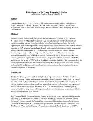
  • 1. 1 Redevelopment of the Proctor Hydroelectric Station A Technical Paper for HydroVision 2016 Authors Heather Martin, P.E. – Project Engineer, Kleinschmidt Associates, Maine, United States Adam Haskell, P.E. – Project Manager, Kleinschmidt Associates, Maine, United States Michael Scarzello – Generation Asset Manager, Green Mountain Power Company, Vermont, United States Abstract After purchasing the Proctor Hydroelectric Station in Proctor, Vermont, in 2011, Green Mountain Power (GMP) undertook a multi-year, phased approach to redevelop nearly all components of the station. Upgrades included reconfiguring and streamlining the intake; replacing a 9-foot-diameter penstock; removing two surge tanks; replacing three vertical turbines installed in 1905 with new, vertical-axis, Francis units; rewinding and restoring the generator of a vertical Francis unit installed in 1926; replacing electrical power and control systems; constructing an access bridge to the power station; and other modifications to improve generation, operation, and safety of the station. Since completion of the project in 2015, the station’s generation capacity has increased from 3 megawatts (MW) to more than 10.23 MW, and it is now the largest of GMP’s 32 hydroelectric generating facilities. This paper describes the redevelopment of an historic, deteriorated, and nearly obsolete project into a modern, reliable, and safe facility and discusses the challenges encountered during the design, permitting, and construction phases of the project. Introduction The Proctor Development is an historic hydroelectric power station on the Otter Creek in Proctor, Vermont. Proctor is owned and operated by Green Mountain Power (GMP) as part of the Otter Creek Hydroelectric Project license. Before GMP purchased Proctor, only one of five turbine-generator units was functional, and much of the station’s infrastructure and equipment needed repair or modernization. Beginning in 2011, GMP implemented a strategic plan to modernize and redevelop nearly all components of the station to increase generation, reliability, and overall safety of the development. The Vermont Marble Company built the Proctor hydroelectric power station in 1905 to supply electricity to its marble factory. Some of the most well-known uses of The Vermont Marble Company’s product include the Tomb of the Unknown Soldier and tombstones for Arlington Cemetery in Washington, D.C. The original hydro station, shown in Figure 1, contained three 750-kilowatt (kW), vertical Francis, I.P. Morris units (Units 2, 3 and 4) and one 1,680-kW,
  • 2. 2 vertical Francis, S. Morgan Smith unit added in 1926 (Unit 1). The power station superstructure is constructed of marble blocks with a timber roof and a marble aggregate concrete substructure. Water was supplied to the units by one 9-foot-diameter, riveted-steel penstock connected to a concrete intake structure located adjacent to a 13-foot-high masonry dam at the top of the adjacent falls. The total installed capacity was 3.9 MW. Figure 1 Original Proctor Hydroelectric Station (Photo Credit: Vermont Marble Archives, Date Unknown) In 1984, The Vermont Marble Company added a 3-MW, vertical Francis, Boving turbine (Unit 5) to the station to generate electricity from additional available flows. To accommodate Unit 5, Vermont Marble expanded the powerhouse, added a new 7-foot-diameter steel penstock and surge tank, and modified the intake. The new unit increased Proctor’s total installed capacity to 6.9 MW.
  • 3. 3 In 2011, Central Vermont Public Service (CVPS) purchased Proctor from Vermont Marble and identified the station’s redevelopment potential. At that time, only Unit 5 was in operation; the four other units had been dormant for several years due to concerns about electrical safety and mechanical issues. GMP purchased CVPS and its generating assets in 2011. This paper describes the multi-year redevelopment and discusses challenges encountered and overcome throughout permitting, design, and construction. Phases of the Redevelopment GMP took a comprehensive approach to the redevelopment project with goals to modernize the components of the station, extend its service life, and limit future maintenance. Careful planning to approach these comprehensive goals optimally was a major part of making this project successful. Kleinschmidt helped GMP divide the project into phases that are shown on a timeline in Figure 2, and in before and after aerial photographs in Figure 3. The phases allowed for the time necessary to obtain approval from the Federal Energy Regulatory Commission (FERC) and permitting agencies, and for efficient and economical design and construction. Also, Kleinschmidt helped GMP plan work such that Unit 5 was on line and generating as much as possible throughout the project. For instance, while the intake was dewatered and under construction, GMP upgraded the neighboring substation to consolidate effort and minimize the time Unit 5 was out of operation. Also, Unit 5 was kept in operation during the work on the penstock and power station for Units 1 through 4 penstock until the new controls and electrical gear needed to be installed in the power station. Figure 2 illustrates the operation of Unit 5. This enabled GMP to continue to generate electricity and revenue from Proctor throughout most of the redevelopment and helped to offset project costs.
  • 4. 4 Figure 2 Phases of the Proctor Redevelopment Project
  • 5. 5 Figure 3 Proctor Station Before (Top) and After (Bottom) Redevelopment (Image © Google, 10/8/2011, 5/5/2016)
  • 6. 6 Phases 1 and 2: Compliance and Feasibility The first two phases of the project began in parallel and involved permitting and regulatory compliance and evaluation of the generation potential and economic feasibility of the redevelopment project. Relicensing was an initial effort because applying for and receiving a new license can take up to 5 years, and significant lead time is required to secure the necessary project approvals. Relicensing and permitting continued throughout the redevelopment project because the project was in the middle of relicensing when GMP acquired Proctor. Feasibility studies involved evaluating the site hydrology and potential energy generation, various turbine- generator configurations, and overall station upgrades and modifications. This was an important first step that provided the information GMP needed to choose the most beneficial options for redeveloping the project. Figure 3 shows the components included in the redevelopment project. Phase 3: Bridge Modifications of the station began with designing and constructing a bridge across Otter Creek to the power station. Prior to the bridge, access was limited to a stair case and a small tramway from the adjacent factory. The new bridge provided safe and reliable access during construction at the power station and also future operation and maintenance. Phase 4: Intake The next phase involved reconfiguring the intake structure and replacing and upgrading the adjacent substation. The intake reconfiguration was chosen as the next phase in the project as a logical sequence in order to have the system ready for full generation capacity once the station improvements were complete. The new intake was designed to increase and streamline flows to reduce head loss and increase generation at the redeveloped power station. It was also designed to increase reliability, reduce maintenance, and accommodate future fish passage. Phase 5: Penstock While designing the intake, Kleinschmidt inspected the penstocks to evaluate their condition and future service lives. Based on that evaluation, GMP decided to replace a portion of the original 9- foot-diameter steel penstock between the intake and the surge tank and to remove both existing surge tanks. The work on the penstock and surge tank was done in parallel with the power station construction to get the infrastructure outside the power station in good condition before commissioning the new units.
  • 7. 7 Phase 6: Powerhouse After the feasibility studies were completed, GMP and Kleinschmidt began the process of procuring three new turbine-generator units to replace the three original 1905 units. Turbine procurement began early in the redevelopment because the new units are expensive items that require long lead times, and are critical for defining the required modifications of the station and generation. Kleinschmidt and GMP began designing the powerhouse modifications after the turbines were selected, during the construction of the intake. In the design we maintained the original superstructure and fit new equipment in the substructure to help reduce construction costs. The three replacement units, Units 2, 3 and 4, fit within the existing bays of the previous units; however, their alignment was altered to reduce head losses and fit within the constraints of the substructure. The new alignment required design and installation of a replacement penstock manifold that directed flow from the original penstock to Units 1, 2, 3, and 4. Other major components of the powerhouse modifications included rewinding the generator and overhauling the turbine of Unit 1, refurbishing three turbine-isolation valves, replacing the generator step-up transformer (GSU), installing new mechanical systems, installing a new bridge crane and roof access hatch at the power station, and upgrading electrical and control equipment. The Challenges of Modernization Each phase of the project had its own unique set of challenges, from requiring license amendments to keep construction of the various components and project as a whole on schedule, to being able to fit the new components creatively within the geometry of the existing structures. The following sections describe the challenges faced during the implementation phases. Phase 1: Regulatory and Permitting Support Kleinschmidt has worked at Proctor since 1981, when we assisted with preparation of an application for a license amendment to install Unit 5, which was performed in 1984. In 2006, then-owner Vermont Marble Power Division of Omya hired Kleinschmidt to provide relicensing services for the Otter Creek Project, which culminated with filing a final license application in March 2010. GMP acquired the project shortly thereafter and filed a revised license application that included a proposal to redevelop the Proctor station. The redevelopment proposal included replacing generating equipment, constructing a new intake, and constructing a permanent access bridge across Otter Creek. GMP needed to construct the bridge in 2012 and the intake in 2013 because of delays in the relicensing process while it negotiated a water quality certification to allow peaking operations at Proctor and to comply with the redevelopment schedule approved by
  • 8. 8 the Vermont Public Service Board. In order to go to construction, GMP first needed regulatory approval from FERC and other agencies. Kleinschmidt consulted with FERC’s compliance staff to facilitate an understanding of the aggressive construction timeframe and to outline strategies that resulted in two separate amendment processes for the bridge and the intake. Kleinschmidt worked with GMP to develop an expedited amendment process by setting the stage to minimize agency review and FERC processing timelines. Developing thorough environmental analyses and amendment application documents and leveraging strong agency relationships enabled Kleinschmidt to help GMP obtain two consecutive license amendments that FERC processed in 1 month and 3 months, respectively. Typically, the amendment processing and approval for similar construction proposals would take 4 to 6 months. Obtaining the amendment in such a short timeframe allowed GMP to complete a substantial portion of the redevelopment process prior to license issuance and to prepare to install new generating equipment immediately after the license was issued. As a result, GMP was able to minimize downtime, improve project efficiency, and accelerate the project schedule. Subsequently Kleinschmidt’s regulatory and engineering staff assisted GMP to obtain FERC certification for production tax credits under the American Recovery and Reinvestment Act of 2009 and American Taxpayer Relief Act of 2012. Kleinschmidt also prepared and submitted an application for certification by the Low Impact Hydropower Institute on GMP's behalf in order to pursue renewable energy credits. Phase 3: Access Bridge Prior to the redevelopment project, access to the power station was limited to a long, steep set of stairs parallel to the penstocks and a small tramway used to transport materials (Figure 4).
  • 9. 9 Figure 4 Proctor Station Prior to the Bridge Construction (Kleinschmidt, 2011) Kleinschmidt and GMP evaluated both temporary and permanent options for improving access to the power station. Temporary options included a floating bridge or a built-up, earthen roadway that required placing fill in the river. GMP elected to install a permanent bridge for several reasons, including the permitting agencies’ strong preference for a permanent option that would avoid placing fill in the waterway and GMP’s concern for the long-term safety of station personnel. Also Kleinschmidt’s studies indicated that the cost of installing and removing a temporary bridge would be only slightly less than the cost of installing a permanent bridge. For GMP, providing long-term, reliable access for construction and future maintenance outweighed the additional cost. Challenges with the bridge design included keeping construction costs low, providing a structure that could carry large equipment during construction and would not encroach on the waterway and restrict flows during a flood. To help keep costs down, Kleinschmidt and GMP kept the bridge as small as possible. The bridge width was kept to a single-lane, and piers were positioned to keep the bridge span as short as possible while minimizing effects on the waterway. Steel, concrete, and pre-cast concrete were evaluated as options for the superstructure; ultimately pre- stressed concrete girders were determined to be the most cost-effective solution.
  • 10. 10 The access bridge consists of two concrete abutments; two concrete piers; pre-stressed concrete girders; a cast-in-place concrete deck; and a side-mounted, steel vehicular guardrail (Figure 5). The bridge spans a total of 265 feet. Since the bridge is a single lane, the deck on the west end (near the power station) is widened to permit large equipment to turn. The hydraulic capacity of the waterway was maintained by setting the bridge elevation above the 100-year flood level, placing the abutments outside of the floodway, and excavating material deposited during recent storms from the bridge area during construction to improve hydraulics at the bridge cross section. Figure 5 Proctor Station with the New Access Bridge (Kleinschmidt, 2013) The bridge was constructed in the summer and fall of 2012. No significant challenges were encountered during construction. As intended, the bridge was used throughout the redevelopment project for equipment transport (e.g., a new 38-ton GSU) and personnel access and continues to be used for station operation and maintenance. Phase 4: Intake Reconfiguration The original intake structure, shown in Figure 6, was found to be hydraulically inefficient and undersized to supply adequate water to the new units. The intake had a narrow entrance at a right
  • 11. 11 angle to the river followed by a winding path through manually operated forebay headgates, trashrack structure, and penstock headgates. To supply adequate water to the new units, the intake needed to be enlarged to increase water flow without increasing water velocity and to be realigned to reduce head loss. In addition, the new intake was designed to pass a minimum flow of 60 cubic feet a second, as required by the new license order, and to accommodate future installation of fish passage. Figure 6 Original Intake, Looking Upstream (Kleinschmidt, 2012) GMP upgraded the substation adjacent to the intake simultaneously with the intake reconfiguration. The existing substation was outdated and undersized for the new generation output. The substation work was purposely scheduled to coincide with the intake work, which already required the power station to be offline, to reduce the amount of time Unit 5 was out of operation. Challenges associated with modifying the intake structure included realigning and widening the structure to increase flow while limiting the extent of modifications to reduce cost, accommodating provisions for minimum flow and the potential addition of fish passage, and including features to reduce operation and maintenance costs for handling debris.
  • 12. 12 The reconfigured intake structure, shown in Figure 7, required demolition upstream of the headgates and significant rock excavation to widen the entrance and make it more hydraulically efficient. A new trashrack structure was designed to provide a cross section adequate to maintain velocities through the racks that are acceptable for fish. The trashracks were equipped with an air-blast system for clearing the racks, and a dual-leaf sluice gate was installed adjacent to the trashracks to allow operators to sluice material more easily. Although the regulatory agencies did not require provisions for fish passage at the intake, GMP installed a gate in the forebay wall to provide a location for passage if it is required in the future. To pass minimum flows, a small slide gate was installed just upstream of a new headgate stoplog panel structure, adjacent to the existing rubber dam abutment. Figure 7 Reconfigured Intake, Looking Upstream (Kleinschmidt) Several significant challenges arose during the construction of the intake. These included working in a constrained space, needing to postpone work due to high water, and overcoming unforeseen geological conditions. Non-competent rock was uncovered in areas where the substrate had been assumed to be solid and competent. Areas of rock along both sides of the intake structure were relatively soft with significant cracking and were considered insufficient for anchoring the concrete walls. The non-competent rock was removed, and structures were redesigned. Overall, the challenges resulted in a prolonged construction schedule and increased
  • 13. 13 total project cost; however, GMP worked with the contractor and Kleinschmidt to complete construction by the end of 2013 and to minimize net effects on the budget and schedule. Phase 5: Penstock Replacement Kleinschmidt inspected the original 1905 penstock, Penstock No. 1, to evaluate its condition and determine if repairs or replacement should be considered as part of the redevelopment project. Penstock No. 2, installed in 1986, was in good structural condition. Both penstocks are shown in Figure 8. The inspection revealed that Penstock No. 1 was generally structurally competent, but a section from just downstream of the intake to the surge tank required significant patching and repair to remain serviceable. GMP proactively chose to replace that section of the penstock to reduce future maintenance and reduce risks for future outages with the new upgraded station. Figure 8 Penstocks and Surge Tanks (Left: No. 1, Right: No. 2) (Kleinschmidt, 2012) Challenges faced in designing the penstock replacement included selecting a new penstock diameter, determining an appropriate method of support, reducing future maintenance requirements, and increasing safety around the penstocks. GMP also wanted to determine the feasibility of removing the surge tanks to eliminate the cost of future inspections and maintenance.
  • 14. 14 Kleinschmidt determined and compared the head loss, total generation gain and revenue, and opinion of construction cost for penstocks 9 feet, 10 feet, and 11 feet in diameter. The original penstock was 9 feet in diameter. The hydraulic analysis showed that the head losses due to friction, and thus generation gain, were comparable for each diameter. Estimated construction costs, however, were significantly greater for the 10-foot and 11-foot pipes due to increased material and the inability to reuse the existing supports. Therefore, GMP installed a 9-foot- diameter, spiral-welded steel pipe supported on the existing continuous foundation of concrete and bedrock. After the existing penstock section was removed, a field inspection found that most of the foundation was intact, and only localized concrete work was required. Reusing the existing foundation instead of installing new supports allowed GMP to save construction costs. Penstock No. 2 was recoated, and both penstocks were buried from the intake to a point just upstream of the surge tank foundations, as shown in Figure 9. Burying the penstocks provided ground cover to insulate the penstocks from the elements (e.g., large temperature changes, precipitation, and ultraviolet radiation). As a result, no costly expansion joints were required, future maintenance (e.g., exterior recoating) was effectively reduced, and safe access for GMP personnel was increased. Figure 9 Final Condition: Buried Penstocks and No Surge Tanks (GMP, 2014)
  • 15. 15 To determine if the surge tanks could be removed, Kleinschmidt modeled the transient water hammer pressures on the penstock system without the pressure relief provided by the surge tank and compared the resulting stresses to the strength of the existing steel penstock. The analysis indicated that both penstocks were structurally adequate to resist the total maximum water hammer and static pressures without the surge tanks. As a result, both surge tanks were removed, and the surge tank openings were closed with steel plate and capped with concrete. Phase 6: Power Station Upgrade and Modernization Modernization of the power station included improving access; replacing the three original, 750- kW turbine-generator units; rewinding the generator and overhauling the turbine of a 1,685-kW unit; replacing the GSU transformer and containment structure; and replacing or upgrading the electrical, mechanical, and control systems. Figure 10 shows the original units and powerhouse. Figure 10 Interior of 1905 Power Station Before Redevelopment (Kleinschmidt, 2010) We faced several challenges in designing the power station modernization. The initial fundamental challenge was trying to maximize generation for available flows while minimizing the cost of structural modification during the selection of the new units. Multiple configurations were evaluated including a single larger unit, a combination of units of varying sizes, and different turbine orientations. Ultimately, to fit within the constraints of the existing substructure,
  • 16. 16 the configuration selected was very similar to the original layout with three new vertical units replacing the existing units. The location of the turbines was shifted to allow the scroll cases to fit between the concrete piers of the substructure and to accommodate modifications of the penstock manifold branches to reduce head loss. These modifications included angling the manifold branches at 45 degrees instead of the original 90 degrees, refurbishing and reusing the existing gate valves, and modifying the manifold geometry. Part of the planning and sequencing included addressing the need for access to the interior of the power station during construction, and later for maintenance. Original access into the power station was primarily through a set of oversized doors. Many of the new, larger turbine components were not able to fit through the doorway (e.g., scroll cases for Units 1, 2, and 3); therefore, a roof hatch was constructed to allow the largest components to be moved into the power station easily with an exterior crane. Prior to construction, Kleinschmidt evaluated the original bridge crane and found it unsuitable to lift heavy components of the three new units and some components of Unit 1. GMP chose to replace it with a new, larger-capacity crane. Anticipating this need enabled the bridge crane to be installed prior to construction so that it was available to the contractor during the power station work. The roof hatch and bridge crane saved the contractor time and provided GMP with a way to perform maintenance on major pieces of equipment in the future. Establishing the baseline layout and construction of the existing power station, a critical first step with any project, proved to be a challenge for the station redevelopment. Information on the original construction and equipment was minimal, and the drawings that were available contained conflicting information. Kleinschmidt surveyed accessible areas of the power station and measured dimensions to confirm the layout. In order to account for the layout variability, Kleinschmidt built flexibility into the design to allow for field adjustment (e.g. slip flanges on the steel manifold). After the units were installed, the next major challenge was positioning and supporting the new electrical equipment in the power station. Space was limited, and clearances were very tight, which required careful planning and removing some non-critical features, such as office space on a mezzanine. Additionally, the concrete floor and columns supporting the switch-gear were assessed and reinforced prior to installing the electrical equipment. Figure 11 shows the interior of the modernized power station. The power station also has all new electrical and control equipment, lighting, HVAC, fire protection and alarms. Outside the power station is a new GSU on an oil-containing support pad and infrastructure for draining storm water.
  • 17. 17 Figure 11 Interior of Power Station after Redevelopment (GMP, 2015) Conclusion Close collaboration and planning between GMP, Kleinschmidt, major equipment suppliers, contractors, regulators, and all parties involved with the Proctor Redevelopment Project enabled GMP to realize the full potential of the site. Through these improvements, the generating capacity of the site was increased from 3.0 MW to 10.23 MW, and the project has achieved a 102% increase in annual generation, a 265% increase in flow capacity, and a 244% increase in generating capacity. Proctor now provides clean, renewable power to 5,300 homes, increases GMP’s clean energy generation and makes Proctor station the largest of GMP’s 32 hydroelectric generating stations. GMP’s implementation of a comprehensive approach to the redevelopment ensures that the station will continue to provide power to future generations of Vermont residents while minimizing risks in the system and reducing major maintenance.
  • 18. 18 Author Biographical Sketch Heather Martin, P.E. Ms. Martin joined Kleinschmidt Associates in 2012 as a structural engineer in the Hydro Resources Engineering Department. Ms. Martin earned her B.S. and M.S. in Civil Engineering from the University of Maine, Orono. Ms. Martin has specialized in structural analysis and design for hydropower facilities including dams, powerhouses, water control gates and rubber dams, and penstocks. In addition to her design activities, she assisted in procurement and construction activities for a wide range of projects. Adam Haskell, P.E. Mr. Haskell joined Kleinschmidt Associates in 2006 as a structural engineer and is a team leader in the Hydro Resources Engineering Department. Mr. Haskell earned his B.S. and M.S. in Civil Engineering from the University of Maine, Orono. Mr. Haskell has participated in many projects including the design of new hydroelectric structures, the rehabilitation of existing hydroelectric sites, and the inspection of penstocks and water retaining structures. Michael Scarzello Mr. Scarzello is an electrical power generation professional with over twenty years of progressive experience in utility operations, asset and staff management, permitting and regulatory compliance, energy project development, construction management, and consulting engineering. A registered Civil Engineer, he has a BS as an Environmental Resource Engineer from the State University of New York at Syracuse, and an MBA from the College of St. Joseph.