SlideShare uma empresa Scribd logo
1 de 97
Baixar para ler offline
Construction and Development of a Vector Flux-gate Magnetometer
Accurate Directional Magnetic Field Measurements
by
Gregory Maxwell Fobes
A senior thesis submitted to the faculty of
the Ithaca College Physics and Astronomy Department
in partial fulfillment of the requirements for the degree of
Bachelor of Science
Department of Physics and Astronomy
Ithaca College
May 2015
Copyright c 2015 Gregory Maxwell Fobes
All Rights Reserved
ITHACA COLLEGE DEPARTMENT APPROVAL
of a senior thesis submitted by
Gregory fvlaxwell Fobes
This tifesis has been reviewed by- the senior thesis conunittec
and the department chair and is recognized as an
Outstanding Senior Thesis
Bruce ThompsnjdvisorDr.
/1616,t%-t- L6e’t-R
Dr. Michael “Bodhi” Rogers, Senior Thesis Corn- Date
mittee Member
Dr. Kellev D. Sullivaftenior Thesis Instructor
J&/
Dr. ttke Keller. Chair. Department of Physics and
Astronomy
(lL]{ 15
Date
v mat4 2ofr
Date J
I understand that my thesis will become part of the permanent print collection
in the Ithaca College Department of Physics and Astronomy Society of Physics
student room. A digital copy will also remain on file in the Department, and
may be distributed within the Department or College for educational purposes.
My signature below authorizes both the addition of my thesis to the student
room collection and the distribution of my thesis for educational purposes.
Mk, 1720/1;
Al
Date U
A’1> 70/j_
Gregory Maxwell Fobes Date
THE ABSTRACT OF THE THESIS OF
Gregory Maxwell Fobes for the degree of Bachelor of Science in Physics
submitted May 2015
Thesis Title:
Construction and Development of a Vector Flux-gate Magnetometer
Accurate Directional Magnetic Field Measurements
This thesis report outlines the proper design, construction, and calibration of
a high precision vector flux-gate magnetometer fit for geological application.
The design implements a ferromagnetic ring core fit within a casing wound with
a sensory coil. The alternating states of permeability within the ferromagnetic
core act as the flux-gate control. Changes in the magnetic flux through the
surrounding sensory coil induce an electromotive force output as a voltage.
Several cores were tested to determine the best core material and geometry
for a high precision and power e cient type flux-gate device. Complex analog
circuitry is detailed for the proper drive current and output signal processing.
Calibrations were made using a Helmholtz coil to test the external magnetic
field strength versus the DC output voltage. Instrument specifications include:
dynamic measurement range (±80 µT), accuracy of measurement (±100 nT),
and resolution (±1.0 nT). The instrument that has been constructed operates
as expected with specifications fit for geological application.
ACKNOWLEDGMENTS
A special thanks to Dr. Bruce G. Thompson for his guidance throughout
the project, Dr. Michael Rogers for leading the archaeo-geophysics team and
further application of magnetometry instruments at Ithaca College, editors
Dr. Beth Ellen Clark Joseph and Dr. Kelley D. Sullivan for their constructive
suggestions, student editors Rafael Ferrera, Stefan Gurgurich, and Charlie
Woodward for their detailed analysis of the report and supportive comments,
and also my family for their continued love and encouragement. I’d like to
dedicate this report to my childhood friend, Christopher Montgomery, who
dreamt of becoming a scientist one day.
Contents
1 Project Background 1
1.1 Magnetic Field Generation and Fluctuation . . . . . . . . . . . . . . . . 1
1.2 Magnetic Prospecting of the Local Field . . . . . . . . . . . . . . . . . . 5
1.3 Magnetometry . . . . . . . . . . . . . . . . . . . . . . . . . . . . . . . . . 8
1.4 Flux-gate development . . . . . . . . . . . . . . . . . . . . . . . . . . . . 9
1.5 Basic Operational Mode . . . . . . . . . . . . . . . . . . . . . . . . . . . 10
2 Theoretical Outlook 13
2.1 Core Geometry and Magnetic field Generation . . . . . . . . . . . . . . . 14
2.2 Hysteresis of Ferromagnetic Materials . . . . . . . . . . . . . . . . . . . . 17
2.2.1 Power E ciency . . . . . . . . . . . . . . . . . . . . . . . . . . . 20
2.2.2 Saturation and Magnetic Permeability . . . . . . . . . . . . . . . 21
2.3 Flux-gate Operation . . . . . . . . . . . . . . . . . . . . . . . . . . . . . 25
2.4 Output Signal Demodulation . . . . . . . . . . . . . . . . . . . . . . . . . 27
2.5 Instrument Calibration . . . . . . . . . . . . . . . . . . . . . . . . . . . . 31
2.5.1 The Earth’s Magnetic Field . . . . . . . . . . . . . . . . . . . . . 31
2.5.2 Helmholtz Coil . . . . . . . . . . . . . . . . . . . . . . . . . . . . 32
3 Instrument Development and Construction 35
3.1 Measuring the Hysteresis of Ferrite . . . . . . . . . . . . . . . . . . . . . 35
3.2 Instrument Construction . . . . . . . . . . . . . . . . . . . . . . . . . . . 41
3.3 Electronic Signal Processing . . . . . . . . . . . . . . . . . . . . . . . . . 42
3.3.1 Primary Excitation . . . . . . . . . . . . . . . . . . . . . . . . . . 43
3.3.2 Sensory Output Demodulation . . . . . . . . . . . . . . . . . . . . 46
4 Measurement Calibration 49
4.1 Helmholtz Coil Design and Construction . . . . . . . . . . . . . . . . . . 49
4.2 Instrument Calibration . . . . . . . . . . . . . . . . . . . . . . . . . . . . 52
4.3 Instrument Stability and Noise Level . . . . . . . . . . . . . . . . . . . . 54
5 Data Analysis - Instrument Specifications 55
6 Discussion of Results 63
xi
xii CONTENTS
7 Conclusion 71
References Cited 78
List of Figures
1.1 Earth’s Magnetic Field . . . . . . . . . . . . . . . . . . . . . . . . . . . . 4
1.2 Daily Fluctuations - Sunrise - DC Magnetic Field Measurement . . . . . 7
2.1 Flux-gate Instrument Design . . . . . . . . . . . . . . . . . . . . . . . . . 15
2.2 Hysteresis (B-H) Curve for Suitable Flux Gate Core . . . . . . . . . . . . 18
2.3 Ferromagnetic Behavior during One Period of Drive Current . . . . . . . 21
2.4 Magnetic Permeability as Flux-Gate Control . . . . . . . . . . . . . . . . 23
2.5 Signal Processing . . . . . . . . . . . . . . . . . . . . . . . . . . . . . . . 29
2.6 Simplified Output Demodulation . . . . . . . . . . . . . . . . . . . . . . 30
2.7 Magnetic Field Production/Cancellation . . . . . . . . . . . . . . . . . . 34
3.1 Circuit Schematic for Measuring Material Hysteresis . . . . . . . . . . . . 36
3.2 Hysteresis Curves of Varying Voltage Drive and Frequency . . . . . . . . 39
3.3 Hysteresis Plot for Suitable Flux-gate Core Material . . . . . . . . . . . . 40
3.4 Primary Excitation Circuit . . . . . . . . . . . . . . . . . . . . . . . . . . 44
3.5 Sensory Demodulation Circuit . . . . . . . . . . . . . . . . . . . . . . . . 48
5.1 Hysteresis of Flux-gate Core . . . . . . . . . . . . . . . . . . . . . . . . . 56
5.2 Output Linear Response . . . . . . . . . . . . . . . . . . . . . . . . . . . 58
5.3 Accuracy of Measurement . . . . . . . . . . . . . . . . . . . . . . . . . . 59
5.4 Noise Response to Zero Field . . . . . . . . . . . . . . . . . . . . . . . . 62
6.1 Project Tools . . . . . . . . . . . . . . . . . . . . . . . . . . . . . . . . . 64
6.2 Application as a Navigational Instrument . . . . . . . . . . . . . . . . . . 68
xiii
List of Tables
6.1 Geographic Magnetic Field Dependence - NOAA Data . . . . . . . . . . 70
xv
Chapter 1
Project Background
The objective of this report is the construction, calibration, and further development of a
high precision flux-gate magnetometer. The design is that of a ferromagnetic ring toroid
wrapped with induction windings and placed within a sensory coil casing. The principles
of design, which outline the proper function of the instrument, rely on fundamental
relationships between electricity and magnetism. Magnetometers of this design are used
in a range of fields, including: astronomical research (Musmann, 2010; Acuna, n.d.),
navigation (Garner, 1987; Lancaster, 1988), archaeology (Aspinall Arnold, 2008), and
geology (B. G. Thompson, 1983; Kaufman, 2008; Edward Tarbuck, 1984; Sharma, 1986).
Further calibration of the tuned output signal allows for a dynamic instrument, capable
of measuring large planetary fields, sensing micro variations of localized anomalies at
Earth’s surface, and characterizing many other electromagnetic sources in between.
1.1 Magnetic Field Generation and Fluctuation
“Magnus magnes ipse est globus terrestris”
The entire world behaves as a large magnet.
1
2 CHAPTER 1. PROJECT BACKGROUND
William Gilbert (1600)
Magnetic phenomena has long been a study of early peoples for a better understanding
of it’s origin and natural occurrences. The application of lodestone’s unique material
attractions and alignments dates back to 50 AD when these rocks were of use in global
navigation (Blakely, 1995). Others sought to take measurement of the earth, atmosphere,
and greater universe to characterize many planetary (otherwise universal) physical laws.
Eventually the first total field magnetic measurement devices were constructed, capable
of measuring a localized magnetic field strength. With rough field measurements and
mathematical models in spherical harmonic analysis, Sir Karl Friedrich Gauss (1838)
proved the existence and internal generation of the all-encompassing planetary magnetic
field of the earth - commonly referred to as the geomagnetic field.
There currently exists a geomagnetic model - the International Geomagnetic Refer-
ence Field - which quantifies the varying three-dimensional components of the magnetic
field strength at any position on the surface of the earth. The strength of the magnetic
field, or rather the magnetic flux density of the directional magnetic field is dependent
on the distance from the source of field generation at the center of the earth, with a
general direction oriented from geographic south to north. The magnetic field strength is
then independent of longitudinal position due to the symmetry of the earth, yet strongly
dependent on latitude, and the altitude above sea level (Kaufman, 2008; U.S.G.S., 2015).
Due to the magnitude and direction of the magnetic field, the needle of a magnetic com-
pass orients itself north/south rather than east/west, forced to point in the same direction
as the field lines when no other magnetic forces are present.
The geomagnetic field is generated by the rotating liquid heavy metal electro-hydrodynamic
outer core of the earth. Accepted theory states that the planet once existed as a red-hot
liquid compound soup, allowing dense metals such as nickel and iron to sink to the center
of the earth due to a strong gravitational force while outer layers began to stabilize and
1.1. MAGNETIC FIELD GENERATION AND FLUCTUATION 3
cool. To explain the large magnetic field surrounding the earth there must be a highly
conductive (rich in free electrons) and pressurized rotating liquid iron-nickel outer core
acting as a powerful magnetic field generator (Sharma, 1986). The concept is similar
to the motion of electrons in a loop of wire - a current which generates a magnetic field
flowing through the loop. The resulting magnetic field behavior is similar to that induced
by a magnetic dipole with field lines emanating from geographic south (magnetic north)
and bending around to point in the direction of north, much like the field pattern of a
bar magnet.
Measurements have shown that the geomagnetic field tends to change in both magni-
tude and direction over time. In a short period of time, within 2000-5000 years, the field
producing outer core may drift a complete 360 degrees relative to the rest of the outer
planet. The study of paleomagnetism - geomagnetic shifts over great periods of time -
yields convincing evidence of these changes as well as the frequent reversal of geomag-
netic polarity approximately every ten-thousand years following a period of continual
field degradation. Recent measurements have shown the magnetic field is now weakening
and approaching another pole reversal. Currently, the geomagnetic poles are located at
78.8 North, 71.0 West in north-west Greenland and at 78.8 S, 109.0 East in Antarc-
tica, displaced 11.5 West from the rotational axis (Sharma, 1986). At these points the
vector field is oriented vertically to the surface of the earth, outward from the southern
magnetic pole and inward to the North.
At the location of the research laboratory, Ithaca College, Ithaca NY, the magnetic
field has a total field strength of approximately 53,160 nT, with angle of inclination with
respect to the ground at 68 deg (See Figure 1.2). In terms of components, the vertical
and horizontal directional magnetic field in Ithaca NY is approximately 49,470 nT and
19,460 nT respectively, changing over time (National Center GeophysicalData, n.d.).
The magnetic field emanating from within the earth has clear e↵ects on exterior at-
4 CHAPTER 1. PROJECT BACKGROUND
N
S
mS
mN
Figure 1.1: Earth’s Magnetic Field (Schematic) This figure is a basic model of the
earth as a giant magnetic field generator. The magnetic poles are represented in compar-
ison with a bipolar bar magnet in which the attraction of a known north pole (as on a
compass) denotes a magnetic south pole. These Geomagnetic poles are subject to change
in magnitude and direction over time (Blakely, 1995).
1.2. MAGNETIC PROSPECTING OF THE LOCAL FIELD 5
mospheric conditions as well. The strong magnetic force fields generated within the plan-
etary mass give rise to the magnetosphere. At this boundary the outermost geomagnetic
flux densities interact with charged plasma from the sun to greatly distort the naturally
occurring magnetic field strength. The field in this region serves an important role as the
boundary for electromagnetic interaction, leading particles into the atmosphere above
the polar regions and protecting the mass of the earth from the sun’s high-energy ra-
diation (Blakely, 1995). The charged particles captured by the strong magnetic field in
the northern and southern polar regions also surrenders a shimmering aurora that can
be seen in the night sky (Knight, 2013).
1.2 Magnetic Prospecting of the Local Field
In a geophysical setting, remote sensing capabilities of electromagnetic sensing devices
act as an reliable method for investigation of the subterranean structures of earth. The
proper sensing tool can often provide details of historical events which have been pre-
served under a several layers of soil. A local magnetic sensing instrument allows for a
study of (shallow/deep) surface soils and regional magnetic prospecting in geology and
archaeology. For each experimental investigation, data collection, and further analysis
beyond the basic sensing capabilities allows for understanding of past human activity and
ongoing geological processes. The instrument of further study, the flux-gate magnetome-
ter, provides a passive measurement technique in which the process of data collection
does not disturb the sources that generate useful magnetic information (Aspinall Arnold,
2008). The source of magnetic contrast (e.g. historical artifacts and burials) may then
remain in situ, not to be disturbed from its original position of rest.
By recording an accurate measurement of the local, directional, and time dependent
magnetic field strength, the source of small field variations and universal interactions
6 CHAPTER 1. PROJECT BACKGROUND
are better understood. Much of ground based geophysical magnetic study is based upon
earth’s material composition and past interactions. A good example of magnetic devia-
tion may result from the uniform (magnetic) dipole alignments in ferrous materials due
to the forces of a directional field - such as that of the earth. At the time that flowing lava
vents began to cool below their Curie temperature, materials (rock formations) would
solidify into fossilized compasses (Lancaster, 1988). The resultant local field which is
stabilized and relatively uniform is then used as a reference point while prospecting for
magnetic disturbances due to composition variation, temperature changes, fluid pockets,
and other physical di↵erences within a larger material volume. Methods of electromag-
netic sounding beyond that of simple magnetic sensing instrumentation has allowed for
the geological analysis of the deep structure of earth. Deep crustal electromagnetic
sounding performed using a large current loop in the Georgia Piedmont showed a sound-
ing depth limit around 30 km into the earth’s crust where a layer of high conductivity
began reducing accurate sensing abilities (B. G. Thompson, 1983).
While searching for localized magnetic anomalies at earth’s surface, it is often small
variations in the field readings (1-10 nT) that can yield clear and interesting results.
While mapping a region for historical evidence of human influences there are often set-
tlement patterns shown by magnetic contrast within the data. This information is used
in understanding early social organizations and gives insight into the formation of human
societies.
One of the first archaeological features to be tested by magnetometry devices were
clay kilns. In these structured holes, clay material high in iron oxide would be heated
to a high thermoremanent magnetization, past their Curie point temperature. In such a
state, the material becomes para-magnetic in which magnetic dipoles readily align with
the directional field of the earth (Aspinall Arnold, 2008). Such materials would then
provide a high magnetic field reading where this occurs. Another historical example, the
1.2. MAGNETIC PROSPECTING OF THE LOCAL FIELD 7
6:30am 1:30pm
52,900
52,905
52,910
52,915
52,920
52,925
52,930
Time of Day
FieldStrength(nT)
Figure 1.2: Daily Fluctuations - Sunrise - DC Magnetic Field Measurement:
This figure shows the measurement of the geomagnetic field of the earth from a station-
ary baseline magnetometer set approximately 1.5 m o↵ the ground, isolated from other
field disturbances for a six hour period. This measurement was taken at Buttermilk
Falls State Park in Ithaca, NY by a Geometrics Cesium Magnetometer provided by the
Ithaca College Archaeogeophysics Laboratory. Measurements of the total magnetic field
strength are taken in the nanoTesla range for this high-precision reliable field instrument
with accuracy within 1 nT. The data reveals many micro-variations in the geomagnetic
field and a notably stabilized diurnal field with patterned changes as the sun begins to
rise.
8 CHAPTER 1. PROJECT BACKGROUND
installation of a housing posts into the ground or any major disruptions to the natural
subsurface layers changes the distribution of soil iron. After back-filled soil mixing occurs,
this location will later provide a magnetic contrast with surrounding undisturbed soils,
indicating some prior event had taken place (Rogers, 2003).
Outside of measuring the variations in the geo-magnetic field and interior properties
of the earth, a precision magnetic field measuring device also allows for the exploration
of inter-planetary (space) characteristics and study of other rotational bodies similar to
the earth. Flux-gate magnetometers are of major importance in outer space magnetic
field measurements due to their simple design, low power consumption and vector re-
sponse characteristics (Acuna, n.d.). Specification capabilities of the instrument can be
characterized in a few categories: upper/lower measurement range, frequency dependent
noise level, and zero drift time and temperature stability. The high-performance based
operation of a flux-gate device will often depend on the specific source under investiga-
tion.
1.3 Magnetometry
Magnetic sensing instruments range in design and function in order to achieve the
proper measurement of a specified electro-magnetic energy source. These di↵erent types
of magnetometers include: proton-precession, optically-pumped (cesium vapor, rubid-
ium, potassium), superconducting quantum interference devices (SQUIDs), Hall-E↵ect
Probes, as well as varying styles of flux-gate magnetometers. Many of these survey
devices - including the Hall-E↵ect probes, optically pumped, and proton precession mag-
netometers - are scalar magnetometers, designed to measure the total field of the earth
at a desired location. Although these instruments have proven their worth in technical
surveys for a range of disciplines, they lack versatility. Hall sensors can be relatively
1.4. FLUX-GATE DEVELOPMENT 9
noisy with large temperature o↵sets, while proton precession devices require excessive
power sources and time for measurement, and SQUIDs need applied coolant such as liq-
uid nitrogen (Ripka Pavel, 1988). The ring-core flux-gate magnetometer, a directional
field sensing vector measurement device, remains the best option for its low power con-
sumption and reliable remote sensing capabilities.
As compared to a total-field measurement device, the flux-gate sensor can detect a
directional magnitude. Vector devices which measure a field strength and direction are of
major importance in the case of source detection and field analysis. Flux-gate devices are
the most precise magnetic field sensors in the mT to nT range. They have the capability
of nT measurement stability and 0.1 nT resolution (Ripka Pavel, 1988). Currently there
are two prominent measurement designs for high sensitivity flux-gate magnetometers,
orthogonal and parallel. The parallel vector type flux-gate magnetometer is understood
to have higher resolution and lower noise. Recent measurements (2009) were between
100 and 10 pTp
HZ
for DC fields or low frequency magnetic fields, taken by I. Sasada and
H. Kashima at Kyushu University in Japan (Sasada & Kashima, 2009). This type of
ring-core, vector measurement, is the design used for further testing in the performance
of the flux-gate magnetometer.
1.4 Flux-gate development
The study of electric and magnetic fields has laid the foreground for applied electronics
and energy control technologies through the principal laws of electromagnetism. Practical
applications of electromagnetic induction includes generators, transformers, navigational
instruments, electrical motors, and high-e ciency switching power supplies. Similar
principals allow for the function of a flux-gate magnetic sensor.
The solid ferromagnetic ring-core flux-gate magnetometer was first introduced by
10 CHAPTER 1. PROJECT BACKGROUND
William A. Geyger in 1961 using a AC voltage drive, similar to present practices (Acuna,
n.d.). Since this time, many others have worked to improve the design for a wide range
of application in scientific research and source detection.
Major advancements in magnetic field sensing technology came during WWII when
these magnetometers were used for airborne detection of submarines. Soon after the
1960’s, patterned magnetic measurements (high-low-high-low intensity) taken underwa-
ter across the north-eastern pacific sea floor supported the theory of frequent reversal in
the geomagnetic field. The iron-rich minerals within hot lava vents at the ocean floor had
oriented themselves with the geomagnetic field before solidifying in position, keeping a
detailed record of the total field polarity along continental plate boundaries (Edward Tar-
buck, 1984). The same information strongly supported the process of sea floor spreading
(Blakely, 1995). These discoveries, made using a flux-gate magnetometer, validated the
theory of magnetic pole reversal and confirmed the theory of continental drift.
1.5 Basic Operational Mode
This flux-gate magnetometer, the ICFG (Ithaca College Flux Gate) design relies on two
coil windings, a primary around the toroid core used for magnetic excitation, and a large
secondary loop fit around the core used as a field sensor. The sense windings rely on
an induced electromotive force due to change in magnetic flux from which a voltage
pulse measurement directly correlates to the vector magnitude of the magnetic field in
the direction of instrument orientation. These flux-gate sensors fit a range of field-
work applications: geophysical studies such as abrupt plate collisions below the earth’s
observable surface as well as geophysical surveys, space exploration of other planetary
magnetosphere, worldwide navigation systems (air, land, sea) and many other fields in
between (Urusan, 2011; MJS Johnston, 1994; Blakely, 1995; Acuna, n.d.; Musmann, 2010;
1.5. BASIC OPERATIONAL MODE 11
Garner, 1987).
The ICFG instrument uses a ferromagnetic material core - a compound of nickel,
zinc, manganese, and primarily iron - with high permeability to channel magnetic field
lines within the core and therefore the sensory coil. The core material is capable of
manipulation by means of an induction winding which can alter the internal properties
of the material such as the relative permeability by means of an induced magnetic field
strength. Using an alternating drive current in the induction coil, rapid states of high-
low permeability force changes in the external magnetic field strength channeled within
the core. With the specific compound and proper resonant frequency input set, the
best possible magnetic sensor can be constructed. In order to read the deviation in
magnetic field, the sensory coil is wound about a rectangular casing and fit around the
ferromagnetic toroid core, which is wrapped with primary drive windings.
For the construction of a flux-gate magnetometer, proper methods of signal processing
on the sensory output is necessary. As originally stated by W.A. Geyger, is important
to design a circuit which may read the second harmonic of the output signal which has
doubled in frequency relative to the drive frequency (Geyger, 1962). Thus the proper
output demodulation and reading of these secondary harmonics can be used in finding
the proportional magnitude of the externally applied magnetic field under investigation
(Primdahl & Jensen, 1987; Araki, 1994; Garner, 1987). In reading this output, a con-
stant or steadily changing magnetic field can be accurately measured. By altering the
frequency, analog circuitry, and material of the toroid core, the goal is to improve the
accuracy, power e ciency, noise, and frequency response of the ring-core flux-gate mag-
netometer. The use of small “coin-sized,” electrically induced ferrous compound cores
and internal magnetic amplification process allows for minimum excitation current (re-
duced in comparison to other tested flux-gate cores) and makes the use of high excitation
frequencies at and above 10 kHz possible (Geyger, 1962).
12 CHAPTER 1. PROJECT BACKGROUND
Chapter 2
Theoretical Outlook
The ICFG has a design based on the theory of electromagnetic induction and direc-
tional magnetic field characteristics. The basic construction and further calibration of a
high-precision flux-gate magnetometer is accomplished through the understanding of the
prior work and scientific experience of others. Scientific authors such as M. Acuna, W.
Geyger, F. Primdahl, and B.G. Thompson, make this project and the further theoretical
advancement of applied physical instruments possible (Geyger, 1962; Primdahl & Jensen,
1987; Acuna, n.d.; B. G. Thompson, 1983).
The model for this research is that of a ring-core geometry wrapped along its circu-
lar path length with induction coils, then inserted within a sensory coil for directional
magnetic field measurements (See Figure 2.1). The process begins with magnetic field
generation in which a concentrated and oscillating magnetic field is generated within
the ferromagnetic core using a high-frequency drive current in the induction coils. The
toroid core is a specific material compound with geometry resembling that of a torus
ring. These ferromagnetic compounds are often a mixture or iron, zinc, nickel, or other
similar permeable metals.
The high precision measurement capabilities of the flux-gate magnetometer relies on
13
14 CHAPTER 2. THEORETICAL OUTLOOK
the physical core compound and its symmetrical geometry (Acuna, n.d.; Garner, 1987).
The high sensitivity, low noise flux-gate device is constructed using small diameter toroid
cores with a large flux capacity and small “L/d” ratio (inductance to diameter). The
simple ring-core design is modeled after H. Aschenbrenner and G. Goubau (1936), revised
by W. Geyger (1962) at White Oak U.S. Naval Laboratory, and improved upon over the
past few decades with higher precision and low noise characteristics (Musmann, 2010).
2.1 Core Geometry and Magnetic field Generation
Through a principal similar to that of a cylindrical solenoid, a concentrated magnetic
field intensity is generated within a ring-shaped metal toroid when a current flows within
the electrically conducting wire. The geometry of the toroid provides a continuous path
for a uniform magnetic field to travel. The simple yet innovative design shown in Figure
2.1 allows for the concentration of magnetic intensity within the toroid along a con-
tinuous closed path along with minimal electromagnetic interference (Francavilla T.L.,
2013). The ring core design also presents the ability to use multiple sensory axes for the
measurement of orthogonal vector components (Garner, 1987). For this report only one
vector direction is measured and therefore one sensory coil is used.
The primary windings around a circular path (enclosing the toroid within) provide
a magnetic intensity much like a solenoid. The magnetic intensity (H) produced within
the induction coil wrappings around the ring is understood by a simple relationship.
~H =
~IpN
l
(2.1)
The magnetic intensity H is proportional to the primary current I, whereas the
e↵ective path length l and number of coils N are held constant by design constraints
(Francavilla T.L., 2013).
2.1. CORE GEOMETRY AND MAGNETIC FIELD GENERATION 15
Signal Generator
+/-
Sensory Casing
Analog
Signal
M
Ferrmagnetic Core
Drive
Winding
Figure 2.1: Flux-gate Instrument Design The toroid core is wrapped completely
around its circular path length with primary induction windings. This allows for the
control of the magnetic field by means of a known current input. An alternating drive
current provides a changing magnetic field and internal magnetization (M) in the core.
The wound core is then fit into a casing wrapped with electrical conductive sensory
windings. By Faraday’s Law, the sensory coil will output an electromotive force which
is proportional to the change in magnetic field strength within the casing.
16 CHAPTER 2. THEORETICAL OUTLOOK
The magnetic field strength ~B within a hollow (air-core) solenoid can be related to
the induced magnetic intensity H,
~B = µ0 · ~H (2.2)
In which µ0 is known as the permeability of free space with a value of 4⇡⇥10 7
Tm/A.
This value is the proportionality constant needed to relate the induced magnetic intensity
given in amps per meter (A/m) to the directional field strength given in Tesla (T) or
Gauss (G). Introducing a medium – such as a ferromagnetic ring-core - within the primary
windings will yield an alternate e↵ect due to inherent internal magnetization and relative
permeability of the core.
The total magnetic field strength (B) produced within the ferromagnetic core by the
introduction of a magnetic intensity (H) is given by,
~B(t) = µ0( ~M(t) + ~H(t)) (2.3)
The time dependent magnetization ~M(t) may vary in magnitude and direction due
to the induced magnetic intensity ~H(t). This internal magnetic strength ranges from
zero to Mmax, the material’s volume specific maximum magnetization strength, which is
much larger than the induced magnetic intensity due to the small amount of current drive
through the primary induction windings surrounding the core. This state of maximum
magnetization and total dipole alignment is known as magnetic saturation. Therefore,
when the core is in a state of magnetic saturation, or Mmax, the total field strength (B(t))
also approaches a maximum value. Equation 2.3 is the characteristic equation used in
the analysis of ferromagnetic materials and further understood through the analysis of
characteristic hysteresis curves.
2.2. HYSTERESIS OF FERROMAGNETIC MATERIALS 17
2.2 Hysteresis of Ferromagnetic Materials
Ferromagnetic materials are iron-like material compounds that have the ability to be-
have as permanent magnets. These materials, specifically because of their atomic struc-
tures and quantum mechanical bonding properties, act unlike ordinary para-magnetic
transition metals with weak magnetic interaction. Ferro-magnets have strong magnetic
properties and require no externally applied field to retain internal magnetization ( ~M).
The evident material magnetization in these particular elements is due to the inherent
magnetic moment (spins) of free valence electrons.
Under the influence of a directional force field, electron magnetic moments tend to
align and create larger magnetic domains (Knight, 2013). In the element iron, this
atomic characteristic is due to two unpaired electrons in the 3d orbital which are free to
interact with other free electrons of similar atoms. The atomic structure of these iron-like
compounds is that of strong magnetic dipoles, active due to the spin of unpaired electrons
(Gri ths, 1989; Aspinall Arnold, 2008). More specifically, the paired electrons within
the ‘s’ orbitals act to shield the (magnetic) interaction between two ‘d’ shell electrons
of di↵erent atoms (Kanamori, 1963). The forces of magnetism caused by these electrons
are then superposed, creating a large magnetic force relative to other materials.
The analysis of the rapid increase, decrease, and reversal of the magnetic field caused
by the high frequency drive current through the coil windings provides information re-
garding the physical properties of the experimental ferromagnetic core. By plotting the
total directional magnetic field strength ( ~B(t)) as a function of the magnetic intensity
( ~H(t)) properties the core material can be obtained in the form of a hysteresis (Garner,
1987; Francavilla T.L., 2013). An example of a hysteresis loop which was measured in
the laboratory is shown in figure 2.2.
At the heart of a high precision ring-core flux-gate magnetometer is the magnetically
18 CHAPTER 2. THEORETICAL OUTLOOK
−600 −400 −200 0 200 400 600
−2.5
−2
−1.5
−1
−0.5
0
0.5
1
1.5
2
2.5
x 10
−5
H(A/m)
B(T)
C
mS
mR
Figure 2.2: Hysteresis (B-H) Curve for Suitable Flux Gate Core This is the char-
acteristic hysteresis curve that has been measured for the given flux-gate core material at
a drive frequency of 300Hz and peak to peak voltage of 37.0 V. The plot shows the total
magnetic field strength versus the magnetic intensity (H) or the proportional drive cur-
rent (I) within the ferromagnetic ring core. Distinct levels of saturation (mS), coercivity
(C), and residual magnetism (mR) are shown.
susceptible core material acting as a path over which magnetic field lines can travel.
The permeability and saturation levels of the induced magnetic core are two important
parameters when choosing a high precision flux-gate core.
The plot in Figure 2.2 shows the non-linear relationship between magnetic field in-
tensity ~H(t) and magnetic field strength ~B(t) for one full period of oscillating input
frequency. With large enough current and proportionally generated magnetic intensity,
the core material is forced into a state of magnetic saturation - when the internal mag-
netic dipoles of the material reach maximum alignment. This alignment and permeability
cuto↵ happens twice, once in each direction for each period of drive current. The near-
2.2. HYSTERESIS OF FERROMAGNETIC MATERIALS 19
vertical linear lines of the hysteresis curve represent regions of high permeability before
and after the core has been driven into magnetic saturation.
There is a well known procedure for testing ferrous compounds used for applications
such as flux-gate core materials. A hysteresis loop shows the magnetization over one
period of alternating input current. The term hysteresis simply implies a lagging time
dependence for the internal state of the material core under the influence of a changing
magnetic field intensity.
The path of hysteresis (see Figure 2.2) begins at the origin moving directly right as
current is sent through the primary coils to induce a magnetic intensity. In the analysis
of ferromagnetic cores a secondary coil is wrapped around the toroid just as the primary
coil in order to sense a changing magnetic flux in the form of an electromotive force. As
the magnetic intensity increases, the magnetization of the core material soon follows and
reaches its maximum value at the saturation flux density (labeled mS in figure 2.2). At
maximum field strength, the once high-permeable core changes state - the flux-gate closes.
The change in relative permeability occurs when the material has reached maximum
magnetization an has no further potential to become magnetized. As the current then
drops to zero the magnetic intensity also drops to zero, however, some residual magnetism
remains (mR). The coercivity levels (C) mark the resistance to magnetization and the
reversal force needed to remove the remnant magnetism. Many characteristics including
those previously stated must be taken into account when choosing the proper core for
the flux-gate instrument.
To measure the total field ( ~B) within the toroid, a sensory coil is wound isolated from,
but similar in fashion, to the primary winding. The primary and secondary windings are
wound using a simple transformer-like configuration around the core. Faraday’s Law
of electromagnetic induction gives the electro-motive force generated in a coil of wire if
the magnetic field passing through the region of coils is changing (Knight, 2013). By
20 CHAPTER 2. THEORETICAL OUTLOOK
integrating the output voltage (emf), the magnetic field (B) within the core at any time
(t) during the cycle of the periodic driving current is given by,
B(t) =
1
N2A
Z t
0
Vout(t)dt + B(0) (2.4)
In which N2 represents the number of secondary turns, A the cross-sectional area of
the toroid core, and Vout the measured output voltage from the sensory winding. The
addition of the initial field strength B(0) is necessary and shows that the internal state of
these materials is time dependent and that the recent history of states must be accounted
for.
2.2.1 Power E ciency
The small magnetic intensity required for magnetic saturation - complete magnetic dipole
alignment - allows for high frequency input as well as low power consumption while mak-
ing high precision measurements. The energy, or physical work, required to reorient the
material domains within the ferrite core is also depicted by the characteristic hysteresis
curve. The area of the plot in the figure shown represents the work dissipated (W), or
rather the energy lost during each period of alternating input current (Francavilla T.L.,
2013). The loss of energy, in joules per cycle, can be determined from measured quantities
of output voltage and primary current over a single period of the drive frequency.
W =
Z T
0
Vout(t)IP (t)dt (2.5)
For a low power, stable, and reliable flux-gate core the hysteresis curve must be
slim, representing low energy loss and high performance. This energy consumption is
important when distinguishing between material cores and in applications for e cient
power transformers. Low power consumption instruments are also in high demand for
2.2.2 Saturation and Magnetic Permeability 21
Figure 2.3: Ferromagnetic Behavior during One Period of Drive Current Shown
is the simplification of how magnetic domains (millions of atomic dipoles) are reoriented
due to the concentration of a magnetic field within the primary induction coils. The
ferromagnetic material acts as a transforming permanent magnet in which the alternat-
ing (current) magnetic intensity drives the material into alternating states of magnetic
saturation Mmax in opposite directions. Note that the changing internal state of the core
also influences the relative permeability. The complete cycle is the same of that shown
by the hysteresis curve in Figure 2.2.
many applications, for example space exploration where power is limited.
2.2.2 Saturation and Magnetic Permeability
It takes energy to introduce a force that has the ability to reorient domains within
a material. Under the influence of a large alternating current, the magnetic intensity
induced within the toroid forces atomic dipoles within the core to align, creating a time
dependent net magnetization ~M(t). If enough driving current is applied through the
induction winding, the core will be forced into magnetic saturation. In this state, internal
22 CHAPTER 2. THEORETICAL OUTLOOK
magnetization reaches a maximum value for the specific material volume. The e↵ect of
internal magnetic dipole alignment is a physical reaction to a magnetic force. Other than
the reversal of electrical induction, the only relief for ferromagnetic dipole alignments are
temperatures above the characteristic Curie temperature or another physical force.
For a large enough alternating drive current magnetic saturation will happen twice,
once in each direction during each period of input frequency. At points of saturation
the relative permeability of the core (µ/µ0) drops to one as magnetic dipoles align in
a unified direction. At this point the magnetic flux lines are expelled out of the core,
producing a rapid change in magnetic field strength within the core.
The literal open-close gate action allowance of magnetic flux through the core is
accomplished by alternating between states of magnetic saturation, changing the per-
meability of the ferromagnetic core. To drive the core into magnetic saturation, a high
frequency alternating square-wave is applied to the primary excitation winding. The
changing saturation of the core acts as a gating mechanism, allowing and resisting the
flow of an external magnetic field through the core material. When the core is saturated
it has low permeability, expelling what external field lines (flux) are contained within the
core. Otherwise, when the core is unsaturated, permeability rises to relatively high max-
imum value and magnetic field lines are drawn within (See Figure 2.7). In this state of
high permeability, while the core is not saturated, magnetic dipoles have not yet reached
maximum alignment and the material acts as a low impedance path for magnetic field
lines to pass through (Garner, 1987).
The magnetic field (B) within a material and the magnetic intensity (H) are related
by the equation,
~B = µR · µ0 · ~H (2.6)
The relative permeability µR representing the e↵ect of the introduced medium (core
2.2.2 Saturation and Magnetic Permeability 23
Saturated Core
Unsaturated Core
Figure 2.4: Magnetic Permeability as Flux-Gate Control For a high frequency
drive current the core material rapidly alternates between these states of low permeability
(magnetic saturation) and high permeability.
24 CHAPTER 2. THEORETICAL OUTLOOK
material) relative to the permeability µ0 of free space. In the core material the relative
permeability changes depend on the internal state and magnetic dipole interactions.
For ferromagnetic compounds with high relative permeability (µR >> 1) the magnetic
intensity (H) generates the total field (B) by the addition of a net internal magnetization.
The relative permeability is given by,
µR =
µm
µ0
(2.7)
The material specific permeability µm is better known as the volume specific magnetic
susceptibility, derived from the material magnetization - the total magnetic moment of
the sample divided by its volume (Aspinall Arnold, 2008). The relative permeability
range is therefore dependent on the material compound. In the flux-gate core material,
changes in permeability occur due to the influence of an alternating magnetic intensity
which forces a change in the internal magnetization.
The true use of the material specific permeability is seen in the relationship between
the net magnetization of a material (M) and the electrically induced magnetic intensity
(H).
B = µmH (2.8)
The characteristic property of these ferrous compounds used in flux-gate cores is stable
magnetization (M) as well as high relative permeability (µr) at coercivity levels when
magnetic domains are disoriented (See Figure 2.2). The permeability of the ferromagnetic
core is dependent on the time dependent state of internal magnetization. Permeability
characterizes a material’s ability to channel the flow of an external magnetic intensity.
The concept is much like a magnetic conductivity - with high permeability, the magnetic
field will move through (be absorbed by) the core to induce further magnetization. For the
2.3. FLUX-GATE OPERATION 25
flux gate core, permeability is a measure of the materials potential to become magnetized.
2.3 Flux-gate Operation
The diagram shown in Figure 2.1 is a simple representation of the design used to mea-
sure the magnetic field strength in one direction through flux-gate control. The ring-core
ferromagnetic toroid is wrapped tight with wire and inserted into the sensory casing.
The signal generator then inputs a large enough alternating current (through the pri-
mary windings) to saturate the toroid with maximum internal magnetization (M) twice,
once in opposing directions for each periodic cycle. At proper resonant frequencies (ap-
proximately 30 kHz) the toroid ring becomes sensitive to any external magnetic field
when alternating between states of magnetic saturation. When the core is driven into
saturation by the induced magnetic intensity, the permeability of the core drops to that
of free space (µ0) and external field lines are expelled from the core. While the core is
alternating between states of magnetic saturation the permeability is high and magnetic
field lines pass though the core. By means of a sensory coil, a rapid change in magnetic
flux due to an external field is output as a voltage (electro-motive force). The output
is then calibrated to an accurate measurement of the directional field strength within a
defined region.
At the instant between states of magnetic saturation, the ferromagnetic core material
permeability (µm) is high and a surrounding magnetic field is channeled within the toroid
core (See Figure 2.4). The resulting e↵ect is then an increased flow of magnetic flux
through the sensory coil winding over the period of high permeability. The drive cycle
then continues to saturate the core in which the material permeability drops and magnetic
flux is expelled from the core. By Faraday’s Law, it is these rapid changes in magnetic
field strength through the sensory coils (flux allowance and flux repulsion) that induces
26 CHAPTER 2. THEORETICAL OUTLOOK
an electro-motive force proportional to the external magnetic field.
" = |
d
dt
|Ns (2.9)
By implementing a sensory coil around the toroid, the changing magnetic flux chan-
neled through the permeable core can be recorded and calibrated to fit a direct field
measurement. For the theoretical calculation, Ns represents the number of wire turns
around the sensory casing and d represents the changing magnetic flux through the
looping of wire.
The flux through the coil is the magnetic field strength through a specified region and
is a scalar quantity.
m = ~A · ~B (2.10)
The variable ~A represents the e↵ective area within the sensory coils with a direction
normal to the area - along the center axis of the coils.
For the application of a flux-gate sensor with fixed rectangular area (A) and number
of coil turns (Ns) the change in flux is given by,
d
dt
=
dB
dt
ANs (2.11)
Therefore an output voltage (pulse) is derived from the electromotive-force as,
Vout = NsA
dB
dt
(2.12)
The important relationship shown here is that the output of the sensory coil gives
a voltage value proportional to the changing magnetic flux passing through the sensory
casing (Aspinall Arnold, 2008). Given Lenz’s Law, electromagnetic nature recoils from
2.4. OUTPUT SIGNAL DEMODULATION 27
a forced change in flux (restores the original state) and therefore produces an electrical
force, or current, in the opposing direction to cancel the unexpected change (Gri ths,
1989). As flux rapidly increases a negative current (backwards flow) pulse is sent through
the sense winding, whereas a decrease in flux density would produce a positive current
flow. Over one full period of input current, this cycle of rapid flux increase and decrease
yields four voltage measurements, two sets of positive then negative output pulses. There-
fore analysis for each signal pulse is done on the second harmonic, or rather twice the
input frequency. With a high frequency input and stabilized output, the voltage pulse
signals are demodulated and thereafter averaged for a reliable direct field measurement
in Tesla.
2.4 Output Signal Demodulation
The raw sensor output due to an external field is a set of oscillating positive/negative
pulses. For each period of drive frequency the core will saturate twice and four flux
changes will be measured – flux out at positive current peak followed by flux in before
the negative current peak, and then repeated. The function of the electronic circuity is
the proper excitation input and output demodulation of the signal. The main focus for
measurement is to invert (every other) voltage pulse to align a signal such that all are
positive (forward) flowing current pulses. Then a baseline average over a short period
of time is a much more precise way of field measurement. The system works using two
4013B CMOS dual flip-flops (think of them as logic NOT gates or inverters) as well
as two 4066 bilateral (high/low) switches. The regulation of the signal is based on the
output frequency, tuned to the 2nd harmonic of the drive frequency using these circuit
components and acts to operate the switches in a fashion that will convert the wave
form to a forward biased high frequency repeating pulse. After this demodulation of the
28 CHAPTER 2. THEORETICAL OUTLOOK
wave form the signal is fed to an averaging amplifier. At this point the repeating pulses
are averaged to obtain a direct voltage output. The polarity (+/ ) of the output value
also indicates field direction (See the next Chapter Methods for the complete circuit
diagram).
The acquired DC output voltage will then correspond (be proportional) to the lo-
calized external magnetic field strength with the slope of the Field Strength vs. Output
Voltage graph giving the necessary conversion factor. Keep in mind that the instrument
orientation is extremely important for single directional field measurements - only the
field traveling through the sensory coil is accounted for.
Figure 2.5 shows the demodulation of the output signal occurs at twice the drive
frequency. Therefore, analysis of the output waveform is tuned to the second harmonic
of the drive current frequency, acting to induce a magnetic intensity withing the primary
coils around the ferromagnetic core.
fout = 2finput (2.13)
The use of a resonant circuit is key in working with high frequency excitation and
response. The role of an LC circuit (inductor and capacitor) is to act as a band-pass
filter allowing only a set range of signal frequencies to exist. The idea is that a set value
of inductance (L) and capacitance (C) provide a periodic time behavior in which the two
components exchange energies. The primary windings around the toroid impose a large
impedance and therefore must be coupled with a specific parallel capacitance to ensure
proper output at the second harmonic of the drive frequency.
The theoretical equation for the characteristic resonant frequency is derived from
Ohm’s Law and the concept of electrical impedance (resistance of non-resistors).
2.4. OUTPUT SIGNAL DEMODULATION 29
L
Out
R
D
A
In
Figure 2.5: Signal Processing This diagram depicts the basic wave forms needed in the
proper function of the high-precision vector flux-gate magnetometer. In represents the
high frequency square-wave input used to e↵ectively drive the core into alternating states
of saturation.L represents the primary winding loaded by the ferromagnetic core. Each
asterisk marks the point of core saturation and drop in permeability. Out represents
the output from the sensory coil when there is a clear and direct external magnetic field
present. Each voltage blip represents a large change in flux during states of switching
permeability (gate-action). R represents a regulating square wave at twice the input
frequency (out of phase) which works with the two electronic 4066 bilateral switches and
two NOT gates to demodulate the output wave form for maximum accuracy. D is then
the demodulated (fixed) signal in which sub-zero pulses have been flipped to match their
partnering positive voltage pulses. A would then represent the output from an averaging
amplifier, a direct measurement proportional to the directional magnetic field strength
being measured.
30 CHAPTER 2. THEORETICAL OUTLOOK
Sensor
IC3-555
Regulator 4066
4066Out
R
D
R*
Out*
A
Figure 2.6: Simplified Output Demodulation (Schematic) This circuit outlines a
major simplification of electrical components and necessary logic to properly interpret
the output waveform from the sense winding. (See Fig. 2.5)
f0 =
1
2⇡
p
LC
(2.14)
The resonant circuit has the ability to amplify signals at the second harmonic of the
drive frequency while ignoring all other noise in the output signal. The input frequency
is set by the 4047B astable mode timer using a known value resistor and capacitor
combination. The use of a high frequency square wave input to force alternating states
of core saturation provides the ability of measuring the magnetic field strength thousands
of times each second, therefore allowing a high precision voltage response output from
the sensory circuit.
2.5. INSTRUMENT CALIBRATION 31
2.5 Instrument Calibration
2.5.1 The Earth’s Magnetic Field
This report is built around the theory that a magnetic field exists at all points in space,
with larger flux densities measured surrounding a magnetic source. Likewise, the earth’s
naturally occurring and known magnetic field strength is dependent on geographic loca-
tion, altitude above sea level, and time. The internal magnetic generating source of the
earth produces a large-scale yet diminishing long-range field strength, directed at a steep
angle as latitudes increase from the planet’s equatorial line. By finding the approximate
magnetic field strength with other reliable devices and with proper theoretical under-
standing, the accuracy of a magnetometer’s measurement can be adjusted for any micro
variations due to time and location. A reliable magnetic reading is used as a baseline
output value to calibrate the magnetometer by testing the accuracy and stability for
precision direct field measurements.
Although the geo-magnetic field is all-encompassing to the planet (See Figure 1.1)
it varies greatly with location and time. At the location of assembly and experimenta-
tion, Ithaca College, Ithaca NY, the present total Earth’s Magnetic field strength has a
theoretical value of 49,579.3 nT (at sea level, in contrast with Figure 1.2) changing at a
rate of -141.1 nT per year. The field also has an angle of declination at approximately
12 10 W, changing by 0 10 E per year (National Center GeophysicalData, n.d.). Measure-
ments taken from within the laboratory environment may di↵er from these theoretical
values by a considerable amount due to magnetic noise from electronics and surrounding
magnetically responsive materials.
32 CHAPTER 2. THEORETICAL OUTLOOK
2.5.2 Helmholtz Coil
This vector type of magnetometer works to measure magnetic field strength in one di-
rection only. The measured magnetic field strength ( ~Bi) through the sensory coil will
depend on the orientation of the flux-gate apparatus relative to the earth’s magnetic
field.
~Bi = ~Bcos✓ (2.15)
Where ✓ is the angle from the axis of measurement ( ~A) to the direction of maximum
field strength.
To begin proper calibration of the flux-gate magnetometer, a known magnetic field
is generated. To test the ICFG device the earth’s field is first nullified to provide a
zero baseline measurement. To produce a known external magnetic field for testing,
a Helmholtz coil is used (See Figure 2.7). The Helmholtz coil is designed from two
large coil wrappings separated by one radial distance from which a theoretically known
magnetic field strength can be produced. The induced magnetic field is dependent on
the geometry of the coils and amount of electrical current flowing through the two coil
loops. This localized field strength produced between the two axial aligned coils can be
used to further test the flux-gate magnetometer device at a range of field strengths, input
frequencies, and positions relative to the coils.
This design grants the ability to cancel the naturally occurring magnetic field strength
of the earth through proper field generation and instrument orientation. This is done by
aligning the Helmholtz coil axis with the known magnetic field direction and generating
a field equal but opposite to the known magnitude at that location. The neutralization
or cancellation of a regional magnetic field allows for proper calibration and noise char-
acterization of the flux-gate sensor when no external magnetic field strength is applied.
2.5.2 Helmholtz Coil 33
From the Biot-Savart law for the magnetic field along a steady line of electric cur-
rent, the induced magnetic field at the center of the Helmholtz coil is derived using the
superposition of charges along the two coil windings (Gri ths, 1989).
BT =
✓
4
5
◆3
2
·
µ0NI
R
(2.16)
In which µ0 is the permeability of free space (air), N is the number of turns for each
of the two coils, I is the direct current value, and R is the radial distance of each coil.
In proper design and calibration the experimental goal is to construct a reliable DC
field measurement instrument. Although many magnetic sources vary with time and have
characteristic frequencies, the instrument is set to output the directional magnitude of a
stabilized field strength. Through the following methods of research the overall accuracy
and noise characteristics of the measurement device will be determined.
34 CHAPTER 2. THEORETICAL OUTLOOK
Figure 2.7: Magnetic Field Production/Cancellation This figure is a simple design
for the Helmholtz Coil in which two large coils of wire are spread one radial distance
apart on the same axis to allow for uni-directional magnetic field generation. The basic
electromagnetic theory of the Biot-Savart Law (Gri ths, 1989; Jian Wang, 2002) is used
alongside other field sensing instruments which were available through the Ithaca College
research laboratory to determine the approximate value of the induced field at the center
of the two coils. The device is used to produce a wide range of magnetic field strengths
and also to cancel the naturally changing and localized magnetic field strength at earth’s
surface in order to test the flux-gate instrument.
Chapter 3
Instrument Development and
Construction
The objective of this thesis report is the proper construction and calibration of a high
precision vector flux-gate magnetometer. A major part of the project was conducted
under the guidance of Dr. Bruce G. Thompson in the electronics research laboratory at
Ithaca College.
3.1 Measuring the Hysteresis of Ferrite
The design of the ICFG was specialized to fit a particular ferrite core of high interest due
to its small dimensions and material characteristics. The final core material selected is
not explicitly known, however it is of the same type used by the Voyager Spacecraft (1977)
and presumed to be of high quality in ferromagnetic response (Thompson, 2014). Further
tests have confirmed this assumption. The material core compound is a major limiting
factor in the simple design of a high precision flux-gate sensor. Similar coin-sized toroid
cores are used as passive inductors for AC filtering with the ability to temporarily store
35
36 CHAPTER 3. INSTRUMENT DEVELOPMENT AND CONSTRUCTION
Rin
Pw Sw
VR
AC Source
M
B
H
Vout
Figure 3.1: Circuit Schematic for Measuring Material Hysteresis Using a
transformer-like configuration, primary coils (PW ) are wound to induce a magnetic in-
tensity (H) within the core while secondary coils (SW ) are wound to measure the change
in total magnetic field (B) as a function of time in large part due to the internal magne-
tization strength (M). The alternating current source measured across the resistor by VR
changed in magnitude, frequency, and waveform, as specific material cores were tested.
Vout provides a measurement on the changing magnetic field strength (B) within the ring
core.
electrical energy in the form of a magnetic field. The primary coil wrapped completely
around the path length of the ferromagnetic core forms a similar (high-grade) type of
inductor in which the magnetic field is controlled and well understood.
In the process of flux-gate core selection, di↵erent geometric and ferromagnetic ma-
terial cores were tested for comparison. A secondary coil is wrapped around the toriod
core similar to the primary winding in a transformer configuration (See Figure 3.1). The
secondary coil allows for the measurement of alternating magnetic field strength within
the toroid as a function of the induced magnetic intensity. This design is unlike the
sensory coil used in the flux-gate magnetometer which is wound about a casing instead.
To collect the data needed to produce material hysteresis curves a Tektronics Oscil-
loscope was utilized to record the alternating input current (Channel 1) across a resistor
(VR) as well as the output voltage (Vout) (Channel 2) as a function of time. The data
3.1. MEASURING THE HYSTERESIS OF FERRITE 37
sets were first stored in a (CSV) Microsoft Excel file, then used for further mathematical
analysis by means of MATLAB computer software (MATLAB, 2012). The current is
calculated from the measurement of VR which is then used to determine the magnetic
field intensity (H) within the toroid. The measurement of Vout is used to calculate the
resulting magnetic field strength (B) as well as the energy dissipated for each cycle as
material magnetic domains were forced into and out of alignment.
Key features of a characteristic hysteresis curve fit for a flux-gate magnetometer core
include regions of high permeability to allow the flow of an external field within the core,
low coercivity representing small magnetic restoring forces, as well as distinct saturation
flux densities, indicating that maximum internal magnetization is achieved (See Figure
3.3). Saturation flux density is a measure of the maximum magnetic induction possible
for a specific core, an intrinsic physical property (Francavilla T.L., 2013; Geyger, 1962).
For instruments with large measurement range and low power consumption, the proper
drive amplitude must be sought in order to ensure magnetic saturation in the core is
achieved with high e ciency.
It takes energy to reorient the magnetic domains within the solid-state ferromagnetic
core. For magnetometers of low power consumption, it is best that the magnetic dipoles
can be re-oriented and maximum magnetization reached with little work done. The work
to force the material into magnetization in each direction, or rather the energy dissipated
per cycle, is proportional to the area inside of the material’s hysteresis curve when distinct
saturation levels are reached and a closed loop is formed. The hysteresis curve depicting
the total field (B) relative to the drive current (I) forming a complete closed loop gives
the total work in terms of the voltage output and current input (recall that electrical
power is the product of voltage and current given in joules per second). By taking the
total sum, or the integration, of this product over one period of drive current the total
hysteresis loss per unit volume, or dissipated work measured in joules is determined for
38 CHAPTER 3. INSTRUMENT DEVELOPMENT AND CONSTRUCTION
each drive cycle.
An initial material toroid was selected to study its hysteresis curve and internal mag-
netic behavior. The material compound was that of iron manganese zinc, determined by
a FairRite Products data sheet. Geometric verification was established using a set of
digital calipers with dimensions of outer diameter, inner diameter, and thickness: 25.40
mm x 15.50 mm x 8.15 mm which matched the manufacturer’s specifications. For the
first material analysis (Test Ferrite 1) 80 ± 1 primary excitation windings and 82 ± 1
secondary sense windings were wound by hand about the path length of the toroid.
To drive the circuit a 4012A BK Presision sweep/function frequency generator was
used. Any further amplification needed to saturate the core was then provided by two
LF411-N operational amplifiers allowing a drive of 25 Vpp (voltage peak to peak) or a
BAA 500 TIRA power amplifier to reach a drive amplitude of 37 Vpp. The resulting
hysteresis plots are shown (Figure 3.2). By simple inspection it can be determined that
this material is not fit for a high-precision flux-gate magnetometer. The specific hys-
teresis curves show the toroid lacks distinct saturation levels at large drive voltages with
a relative permeability that is low in comparison to other ferrous materials. Material
saturation occurs during maximum dipole alignment, when the internal core reaches a
steady (constant) total magnetic field strength. While the vertical axis of the hysteresis
plot measures total field strength this occurrence is represented as a near horizontal line
at the top and bottom of the curve. The path of hysteresis occurs in such a way because
the internal magnetization (M) provides the large part of the total field strength (B).
The magnetic intensity (H) driven by the induction coils acts primarily to lead the e↵ects
of internal magnetization, continuously altering the states of the core. According to the
computer (MATLAB) approximation, the energy dissipated per cycle is less at higher
frequencies for this particular core.
A second material core was then selected to find a better core for a low-power, high
3.1. MEASURING THE HYSTERESIS OF FERRITE 39
−500 0 500
−3
−2
−1
0
1
2
3
x 10
−5
Test Ferrite − 15Vpp at 100Hz
H (A/m)
B(T)
−500 0 500
−3
−2
−1
0
1
2
3
x 10
−5
Test Ferrite − 25Vpp at 100Hz
H (A/m)
B(T)
−500 0 500
−3
−2
−1
0
1
2
3
x 10
−5
Test Ferrite − 37Vpp at 300Hz
H (A/m)
B(T)
−500 0 500
−3
−2
−1
0
1
2
3
x 10
−5
Test Ferrite − 37Vpp at 100Hz
H (A/m)
B(T)
W = 112µJ W = 108µ J
W = ??? W = 85µJ
Figure 3.2: Hysteresis Curves of Varying Voltage Drive and Frequency These
plots represent the initial hysteresis analysis for a single toroid core. The plots represent
the changing inputs of drive current amplitude and frequency for a sinusoidal waveform.
At 15 Vpp 100 Hz the core was not driven into saturation, the energy dissipated is not
calculated due to the small overlapping loops at maximum field strength (B). At 25 Vpp
at 100 Hz a hysteresis loop is depicted however the clear saturation levels are still not
achieved. Although both plots (100 Hz and 300 Hz) at 37 Vpp show hysteresis curves
with saturation levels, the work loss is much higher than preferred. Also, the relative
permeability represented by the transitions between saturation levels should be vertical,
representing rapid flux changes in the core.
40 CHAPTER 3. INSTRUMENT DEVELOPMENT AND CONSTRUCTION
−500 −400 −300 −200 −100 0 100 200 300 400 500
−8
−6
−4
−2
0
2
4
6
8
x 10
−7
H(A/m)
B(T)
W = 1.2µ J
Figure 3.3: Hysteresis Plot for Suitable Flux-gate Core Material This plot repre-
sents a much more suitable material toroid for use in flux-gate instrumentation relative
to that shown in Figure 3.2. It is fabricated to operate at high frequency drive currents
( +20 kHz) as opposed to the previous low frequency core. Scaling di↵erences along the
y-axis yield a much smaller enclosed loop than that of the previous hysteresis analysis,
meaning less work is required to saturate this material core each cycle. With a drive
of 20 Vpp and frequency of 20 kHz the curve shows excellent characteristic properties
for a flux-gate core material. Horizontal levels represent the distinct saturation levels
or maximum magnetization in each direction. The vertical transitions depict periods of
high permeability within the core, when external magnetic flux is drawn in.
3.2. INSTRUMENT CONSTRUCTION 41
precision flux-gate magnetometer. The material compound is unknown but measured by
dial calipers with dimensions of outer diameter, inner diameter, and thickness: 18.90 mm
⇥ 14.54 mm ⇥ 3.00 mm. The resulting hysteresis curve is shown (figure 3.3). In this case
there were approximately 141±2 primary excitation windings and 89±1 secondary sense
windings. Further testing of di↵erent material cores determined that with clear regions
of permeability and levels of saturation at a drive voltage of 20 volts peak to peak and
20 kHz, this second core is a major improvement.
The ability of the core material to perform at high frequencies is important for pre-
cision instrumentation. A high frequency drive current (greater than 10 kHz) allows
the core material to cycle through the hysteresis cycle of saturation and high relative
permeability more rapidly. This e↵ect yields more flux induced output sensory pulses
and therefore more field measurements per unit of time. Although the instrument is set
to measure direct field characteristics, more measurements per second provides higher
accuracy for changing magnetic field strengths.
3.2 Instrument Construction
The overall dimensions of the instrument body and sensory casing were determined by
the dimensions of the best suited material toroid for use as a flux-gate magnetometer
core. Accurate measurements are made using dial calipers allow for the calculation of
the e↵ective path length of the toroid needed for the previous calculation of the induced
magnetic intensity as well as the proper dimensions for a tight fit sensory casing.
The sensory casing was custom-designed using AutoCAD design software to allow for
a single sensory winding around the body of the toroid (AutoCAD, 2014). To construct
the case a Makerbot Replicator2 3D Printer was utilized (MakerBot, 2014). The print
was made of a non-toxic corn based PLA (plastic) filament which allowed for minimal
42 CHAPTER 3. INSTRUMENT DEVELOPMENT AND CONSTRUCTION
magnetic interference. Multiple sensory casings of similar design were printed to allow
for di↵erent numbers of coil turns on each. Although the toroid used in the instrument
application was previously wound by the manufacturer with primary excitation windings,
all sensory windings about the casing were wound by hand with 32 gauge wire. The first
sensory casing has approximately 70 ± 1 coil turns while the second casing of similar
design has approximately 200 ± 2.
The inductance of the primary coil and secondary coils was determined with a BK
Precision 879B LCR meter at 1 kHz. The inductance measurements of the excitation
coil and first sensory casing were approximately 3.20 mH and 39.40 µH respectively. With
the core placed within the first sensory casing the inductance of the sensory casing then
increased to 77.5 µH. Likewise, a second sensory casing was measured with inductance
of 405.5 µH with the core in place. These inductance values are important for proper use
in electronic circuitry for primary coil excitation and output signal demodulation.
3.3 Electronic Signal Processing
List of electronic components
Excitation Circuit:
- CD4047 astable/monostable multivibrator timer (RC set)
- CD4013 CMOS Dual D-type Flip-flop
- PN2907A PNP Bipolar Transistor
- MPS2222A NPN Bipolar Transistor
- IN5282 Diode (4)
- 4.0mH Inductor (Choke)
- Specified Values: Resistors, Capacitors (polarized/tantalum and non-polarized)
Sensory Output Circuit:
3.3.1 Primary Excitation 43
- CD4066B Quad Bilateral Switch (2)
- OP227G Operational Amplifier (3)
- Specified Values: Resistors, Capacitors (non-polarized)
Other Equipment: Power Supply, Oscilloscope, Multi-meter, BNC cables, bread-
board, wires, etc.
3.3.1 Primary Excitation
The circuit design was adopted from a design developed by Mario H. Acuna of the
NASA Goddard Space Institute in Maryland and further tested and calibrated to fit
the toroid/sensory coil currently in use (Thompson (2014)). The circuit is used both
to stabilize the excitation of the primary winding to ensure a steady frequency drive
and hysteresis behavior as well as provide a precise output voltage proportional to the
external magnetic field through proper signal demodulation. These two objectives are
the purpose of the excitation circuit (Figure 3.4) and the sensory demodulation circuit
(Figure 3.5).
The excitation circuit (See Figure 3.4) has four major sections in which the drive
signal is prepared for the proper excitation of the primary coils used to induce a magnetic
intensity within the core:
In section A the 4047 Multivibrator is used as a frequency set timer in astable mode.
With the proper RC combination, a desired and stabilized frequency square wave pulse is
set. The desired frequency output of the 4047 was sought at 32 kHz for highest precision
measurements. Using both a theoretical formula from the CD4047 data sheet coupled
with experimental outcomes the frequency output from the multivibrator chip is set at
31.79 kHz using a 603 ⌦ resistor ( Rset ) and 10nF capacitor ( Cset ). The output (Q) and
the inverse (/Q) square-wave signals are then relayed via Q1out and Q2out to control the
bilateral switches in Figure 3.5 which are used for demodulation of the sensory output.
44 CHAPTER 3. INSTRUMENT DEVELOPMENT AND CONSTRUCTION
Figure 3.4: Primary Excitation Circuit
3.3.1 Primary Excitation 45
The multivibrator output signal (Q) also serves as the input for the next section of the
circuit.
In section B the signal from the astable timer is the input to the clock of the CD4013
Dual Flip-flop. Much like the astable timer the output of the flip-flop is bistable with only
high or low square-wave output states. The clock input of the flip-flop is edge-triggered
to alternate due to a sudden change in voltage from low to high only. The output signal
(Q) is read from data (D) at the edge trigger of the clock (CLK) at precise intervals. Both
reset (R) and set (S) are held low at -5 V to ensure a constant frequency output. Due to
frequency dependence on the up-swing (low-high) of the input, this CMOS Dual Flip-flop
accurately divides the input frequency by two. Therefore if a 32 kHz square-wave signal
is input to clock then a 16 kHz square-wave signal is produced at the output (Q).
The excitation current signal then flows to section C where PN2907A PNP and
MPS2222A NPN Bipolar Transistors form a push-pull amplifier. The use of bipolar
junction transistors allows for an amplification process with little distortion of the wave-
form with high e ciency while increasing the power output (B. G. Thompson, n.d.). In
this case the drive voltage is increased from 10 Vpp to 24 Vpp (peak to peak voltage)
maintaining a similar square waveform of the same frequency. This increased current
(power) capability is important to properly excite the primary coils and drive the core
into cycles of magnetic saturation when the relative permeability drops and field lines
are expelled out from the core.
The final section D of the excitation drive circuit acts as both an integrator filter
and resonant filter. After leaving the push-pull amplifier in section C the waveform
closely resembles a square wave but is then converted into a triangle-like wave form of
positive and negative pulses by the capacitor-inductor combination in series. The same
components act as a low impedance path for the specific drive frequency. The driving
pulses feed energy to the resonant circuit of the parallel combination of capacitor and
46 CHAPTER 3. INSTRUMENT DEVELOPMENT AND CONSTRUCTION
primary induction windings, which together act to stabilize the current and furthermore
send regular pulses of electrical energy through the primary windings.
3.3.2 Sensory Output Demodulation
The sensory circuit (See Figure 3.5) has been divided into four major sections in which
the output signal from the sensory coil is demodulated to provide an output voltage
proportional to the external field strength.
The first section J of the output circuit provides proper resonance of the signal.
More specifically, matching the inductance of the sensory coil with the proper capacitor
in parallel, the resonant frequency is set to match the known frequency of the output
signal. This allows for the cancellation of any high/low frequency level noise and the
proper reading of the sensory output for further amplification and demodulation. Finding
the proper resonance is di cult because the inductance of the sensory coil is subject to
change when loaded by electronic signal and other components. For the best results a
guess and check method was used in which the theoretical capacitance was set, thereafter
altered until the proper wave form was achieved. The desired signal output from this
section to the operational amplifier should be a clean sinusoidal wave, properly phased
with the CD4047 square wave output with the same frequency.
With proper resonance achieved the remaining amplification process may begin. In
section K the first operational amplifier acts to increase the signal strength by a factor
of five, given by the ratio of input to feedback resistance values on the amplifier. This
allows for a stronger output signal and higher sensitivity measurements. At the output
of the first amplifier the signal is then split for further demodulation.
The purpose of the circuit elements in section L is to provide full wave rectification.
What was a set of oscillating (±) amplified pulses is then converted into a waveform with
current pulses oriented in one direction only. The process is done using each of the two
3.3.2 Sensory Output Demodulation 47
CD4066 bilateral switches, controlled by the output and inverse output of the astable
timer from the excitation circuit. The control works in such a way that when one switch
is open the other switch must be closed. The second operational (inverting) amplifier
acts to simply invert the signal it receives (voltage gain of 1 equal to the resistor ratio)
before arriving at the second bilateral switch. By means of full wave rectification the
highest precision measurements are made taking all output current pulses into account.
The proper demodulation at this point also allows for a measure of field polarity, the
known direction of the magnetic field. If demodulated current pulses are all positive then
magnetic field lines are passing forward through the sensor, while negative pulses would
indicate field lines in the opposite direction.
The final part of the sensory demodulation is section M in which an averaging am-
plifier is used. The feedback RC parallel combination allows for the accurate averaging
of the signal to provide a DC output voltage. This is the baseline measurement which
is proportional to the external field being measured. Further calibration and field mea-
surements provide the proper proportionality constant necessary to convert the direct
voltage output to a measurement in Tesla. The same RC combination acts as a low-pass
filter against high frequency measurements. Because this device is set to measure only
direct field characteristics, the cuto↵ limit is set at approximately 5 Hz to cancel any
readings of high frequency noise.
Also in this section is a feedback to the sensory coil. This feedback system allows
for the further cancellation of additional field generation due to induced current flow in
the sensory casing. The design is that in which the direct current value flowing through
the feedback wire is set to cancel only the readings due to this minor e↵ect within the
sensory coil. In the final adjustments of the overall circuit gain only feedback resistor
will need adjustment.
48 CHAPTER 3. INSTRUMENT DEVELOPMENT AND CONSTRUCTION
Figure 3.5: Sensory Demodulation Circuit
Chapter 4
Measurement Calibration
4.1 Helmholtz Coil Design and Construction
The ICFG instrument was set to take magnetic field readings for further fine tuning and
calibration. The use of a Helmholtz coil (HHC) (See Figure ?? from Theory) allows
for the generation of a known magnetic field strength within the center of the two coils
which can be used to test the DC output of the flux-gate magnetometer. The coils were
selected to be much greater than the instrument body to allow for a uniform magnetic
field strength that encloses a large region allowing for precise (within 1%) field generation.
Using the Biot-Savart Law for the magnetic field generated by an electrical current,
the theoretical magnetic field strength was calculated in terms of the current, number
of coil windings, and the radius of the loops of wire. For the generation of a steady
magnetic field strength at the center of the HHC apparatus the current must be flowing
in the same direction in each coil and the distance of separation between the coils must
be that of one radial length. To reverse the direction of the magnetic field one can simply
reverse the direction of current.
The Helmholtz design and construction was completed at Ithaca College within the
49
50 CHAPTER 4. MEASUREMENT CALIBRATION
machine shop of the Center of Natural Sciences building using the provided tools and
professional guidance of instructors Jennifer Mellott and Bruce Thompson. A local busi-
ness (Johnny0
s Warehouse) donated a large polyethylene section of ribbed pipe for the
two ring mounts of the Helmholtz coil. The material pipe measured 32 cm in diameter
which was considered large enough to produce a well-known field strength and allow for
minimal electro-magnetic interference. For this design, the two identical polyethylene
mounts are spread 16 centimeters (one radial distance) apart. Using 20 gauge copper
wire, 20 coil wrappings were wound about each of the two mounts.
This design allows for a well-known, concentrated magnetic field at the center of the
two large coils. The two mounts were set in position on a long wooden base board by
multiple plastic screws and secured with another board screwed in on the top of the
plastic polyethylene coil mounts. With the number of turns and radius of the coils set,
the direct current input is then the only factor determining the strength of the magnetic
field between the coils. By wiring the two coils in series with a one ohm (1 ⌦) shunt, a
voltage reading across the shunt using a Fluke 29 voltmeter provides an accurate current
measurement by Ohm’s Law.
Theoretical calculations based on the given parameters and the superposition of the
Biot-Savart field as well as the International Geomagnetic Reference Field yields the result
that roughly 0.5 Amperes of current through the Helmholtz apparatus would cancel the
total field strength of the earth at the location of the research laboratory. In order to
cancel the entirety of the directional geomagnetic field in this small region, the central
(two-coil) axis of apparatus must be aligned parallel to the direction of the magnetic field
and a field equal and opposite in direction must be generated, creating a null e↵ect.
To test the accuracy of the field produced by the HHC, another device, the Hall-
E↵ect Probe, was available and utilized to measure total (non-directional) magnetic
field strengths. The device outputs a voltage magnitude in response to surface currents
4.1. HELMHOLTZ COIL DESIGN AND CONSTRUCTION 51
produced by a proportional magnetic field. The device had been previously calibrated to
fit a linear equation relating voltage output in Volts to magnetic field strength in Tesla –
this is a similar procedure to the final linearity calibration of the flux-gate magnetometer
output. The Hall-E↵ect device has both a radial and transverse setting as well as an
o↵set knob with the ability to ignore the naturally occurring field and measure only that
which has been produced by the HHC.
Several sets of data were taken by the Hall-E↵ect Probe for further analysis of the
performance of the HHC at a range of direct input current values from 0 - 2 Amperes.
The noise level on the device has been determined to be at ±5.0 mV which is equivalent to
approximately 0.1 Gauss (G) or 10 micro Tesla (µT) variation - given that 1 T = 104
G.
With the Earth’s total magnetic field strength at approximately 50 µT in Ithaca, NY, the
measurement error is nearly ±20 percent and does not allow for fine tuned measurement
calibration for the Helmholtz coil and thereafter the flux-gate magnetometer instrument
(National Center GeophysicalData, n.d.).
Although quite noisy and unstable, the Hall-E↵ect Probe upholds the theoretical
predictions of the Helmholtz coil and proves that it functions with the proper response
to di↵erent drive current values with decreasing field strength when moving away from
the center of the two large coils. With proper error taken into account, the Hall-E↵ect
measurements of magnetic field strength directly correlates with theoretical input values
of coil radius, number of wrappings, and direct current values. In the best scenario using
the Hall-E↵ect probe, measurements from zero to two Amperes were within ±4 µT for the
discrepancy between theoretical and measured total field values. With the verification
of Hall E↵ect Probe measurements, the theoretical calculated magnetic field strength at
the center of the Helmholtz coil was used for further testing of the ICFG.
52 CHAPTER 4. MEASUREMENT CALIBRATION
4.2 Instrument Calibration
Instrument calibration is performed in order to determine a precise and reliable Tesla
measurement for the magnetic field strength in the small region surrounding the flux-gate
magnetic sensing instrument. The process includes the analysis of instrument capabilities
including dynamic range, time and temperature stability, as well as frequency response.
To begin the calibration process, the orientation of the sensor was altered providing
strong evidence of proper functionality in that the strongest output signal was in the
known direction of the magnetic field according to the latitude of measurement here
at Earth’s surface. Due to the directional measurement characteristic, the output is
nullified when orientation is set perpendicular to the geomagnetic field lines. Further-
more, simple bar magnets forced severe shifts in output voltage as their local proximity
to the instrument was changed, validating instrument performance in the presence of
non-geomagnetic external fields.
The Helmholtz coil (HHC) is the most accurate field source available. The apparatus
allows for the cancellation of the magnetic field and can test the flux-gate instrument at
a wide range of directional field strengths. For simplicity the Helmholtz coil is first used
to cancel the earth’s horizontal magnetic field. E↵orts are made to ensure the orientation
of the axial direction of the apparatus points to the north, allowing for the maximum
horizontal field strength to be nullified.
By means of a stage at the center of the HHC, the small flux-gate instrument is
mounted within the Helmholtz coil and set to run while current values through the large
coils are altered producing well-known magnetic field strengths. The first objective of
instrument calibration was to check the linearity of measurement and define the instru-
ment’s dynamic range the upper and lower limits of accurate measurement capability.
The field strength within the Helmholtz coils was first nullified, therefore producing
4.2. INSTRUMENT CALIBRATION 53
a zero output voltage from the magnetic flux-gate sensing instrument at the center.
Collection of data in the form of direct current input (I) versus output voltage (Vout)
is made to create a linear plot in which output voltage is proportional to the magnetic
field strength and therefore also to the current flowing within the HHC. For example,
the DC voltage output of the instrument should increase by the same factor as that of
the strength of the field within the HHC – twice the output meaning twice as large the
magnitude of the directional field. Any errors are remeasured and properly defined for
proof of stability for which a known o↵set measurement can be provided.
Data collection began by altering the current supply through the HHC to set field
strengths ranging from zero to the upper limit. The same procedure was conducted
by reversing the current until the lower limit was reached. The limits of measurement
are characterized by points in which functional behavior becomes nonlinear, when the
output voltage is no longer proportional to the magnetic field strength. These critical
points are determined by the limitations in electronic circuitry. More specifically, it
is the power supply operating the averaging amplifier in the final leg of the sensory
demodulation circuit (set at ±15 V ) which determines the range of measurement. The
range of measurement may also be increased or decreased by altering the total circuit
gain. Otherwise for large external field strengths, the limited range measurement is reliant
on the core material specifications (such as saturation levels) and may be improved or
reduced by means of a di↵erent material volume.
Also conducted was a series of frequency response measurements. By driving an
alternating current through the HHC at a known frequency, an induced magnetic field
strength oscillates within the center of the HHC at the same frequency. The instrument
DC voltage output was then measured as a function of the frequency of the magnetic
field. By using an tuned feedback capacitor and feedback resistor on the final operational
amplifier (the averaging amplifier, section M in Figure 3.5) a low pass filter is created
54 CHAPTER 4. MEASUREMENT CALIBRATION
which allows only the measurement of magnetic field strengths below 5 Hz.
4.3 Instrument Stability and Noise Level
To test the stability of the instrument the field is again canceled using the HHC, or
nullified using a mu metal shield - a high permeable material acting as a magnetic barrier.
This provides a baseline measurement for which the noise sensitivity can be quantified
over a set interval of time. By extracting data from the Tektronics oscilloscope and
using MATLAB computer software, an true RMS reading of the voltage fluctuations
that deviate from the mean baseline value is calculated. By doing this with a Mu-metal
shield, the possibility of fluctuations due to the HHC, analog circuity, or noise in the
power supply is removed. With a stable magnetic field strength generated within the
HHC this process is done at a range of magnitudes, and frequencies, to test for similar
noise characteristics.
Tests for temperature stability of the instrument are similarly made using a heat
source, dry-ice (frozen CO2), and Styrofoam cooler to create a range of known tempera-
ture di↵erences while the instrument is powered and properly functioning under influence
of a stable magnetic field strength. This allows output measurement variations to be mea-
sured in order to determine a temperature range in which reliable measurements can be
made.
Chapter 5
Data Analysis - Instrument
Specifications
The process of data retrieval and analysis provides the means by which the capabilities
of the vector flux-gate device can be quantified. Instrument specifications that will be
discussed include: dynamic measurement range, sensitivity of measurement, and overall
noise characteristics. The vector flux-gate magnetometer that has been constructed is
intended to measure magnetic field strengths in range of Earth’s naturally occurring
magnetic field with maximum accuracy and directional dependence.
Hysteresis measurements, as discussed previously (See Chapter: Theory and Meth-
ods), provide information on the ferromagnetic response of the material core. The specific
material compound in use is high quality in that it operates at high frequency drive cur-
rents (+30 kHz) and alternates between states of internal saturation (permeability cuto↵)
with low power consumption. This is shown in Figure 5.1 by the amount work dissipated
per cycle. Measuring the hysteresis of ferrite materials is important when choosing a
core compound for a particular flux-gate magnetometer. The design specifications of the
instrument are that of low power consumption and high sensitivity.
55
56 CHAPTER 5. DATA ANALYSIS - INSTRUMENT SPECIFICATIONS
−500 −400 −300 −200 −100 0 100 200 300 400 500
−8
−6
−4
−2
0
2
4
6
8
x 10
−7
H(A/m)
B(T)
W = 1.4 µJ
Figure 5.1: Hysteresis of Flux-gate Core The plot shows the hysteresis behavior of
the core for the conditions under which the instrument operates. The alternating input
(drive voltage) used to induce a magnetic intensity (H) within the core is a triangular-
like waveform set at 32 kHz with a maximum voltage of approximately ± 15 V. The
characteristic shape of the plot shows distinct saturation levels when magnetic flux is
expelled from the core (horizontal lines) along with intermediate transitions of high per-
meability when flux is channeled within the core (vertical lines) - producing a changing
magnetic field through the sensory coil. Work, measured in Joules, is determined by the
integration of the time dependent output voltage and drive current, calculated to be 1.4
µJ per cycle under these conditions. The alternating state of material magnetization
within the ferromagnetic core is at the heart of flux-gate instrumentation.
57
Data acquired from the DC output voltage is recorded at a range of magnetic field
strengths (as provided by the Helmholtz coil) in order to characterize the constructed
instrument’s sensing capabilities. The output voltage response must correlate to the di-
rectional magnetic field strength that it measured to ensure the proper function of the
instrument. The field response (output voltage) also changes in both magnitude and
polarity as the orientation of the instrument is varied - as expected for a vector measure-
ment device. The instrument is designed to measure accurate field strengths within the
± 80 µT range, containing all current directional magnetic field strengths at the surface
of the earth. Deviations in the measurement of magnetic field strengths beyond this
accepted measurement range are expected and acceptable. This range is based on the
application of the ICFG as a geological based instrument, due the physical limitations of
the instrument components and e cient power sourcing for complex circuitry. A set of
output voltage response versus magnetic field strength data is shown in Figure 5.2.
The linearity of the output shown in Figure 5.2 ensures a stable output response to
a large range of magnetic field strengths as measured by the instrument. The two plots
shown in Figure 5.3 are similar to those in Figure 5.2 where the data is truncated to fit the
accepted range of output response values, the linear portion of the plot. Using MATLAB
computer software (MATLAB, 2012), a basic fit to the data provides a linear equation
in which the slope of the plot serves as the best conversion from DC output voltage to
micro Tesla, revealing the directional field strength of the surrounding magnetic field.
The residual plot and norm of the residuals then depicts the accuracy of the line of best
fit. There is no evident pattern in the data, however, the largest residual values are within
±0.04 V and are at the outer most magnetic field strengths (approx. 75 µT). Using
the conversion factor (slope of best fit line), the corresponding magnetic field accuracy
of measurement is found at ±200 nT. Almost all other residual values lie within ±0.02
V which corresponds to measurement accuracy of ±100 nT.
58 CHAPTER 5. DATA ANALYSIS - INSTRUMENT SPECIFICATIONS
−300 −200 −100 0 100 200 300
−15
−10
−5
0
5
10
15
Magnetic Field Strength (µT)
DCOutputVoltage(V)
Figure 5.2: Output Linear Response The output voltage response to a changing mag-
netic field strength is shown. The linearity of the figure within the limited measurement
range shows the instrument has reliable sensing capabilities in which the output voltage
correlates to direct field measurements. The proportionality constant given by the slope
of the graph ( V
µT
) provides the conversion factor between the two measurements. The
Fluke 8050a digital multimeter used to measure voltage output has accuracy of ±0.03%
in the first 2 output digits (FLUKE, 1979). The rugged design and long-tested theory of
the Helmholtz coil provides information that the field generated at the center is within 1%
accuracy. In each of these cases - measurement of DC output voltage and field strength
in Tesla - error bars cannot be drawn to scale and are therefore neglected.
59
−80 −60 −40 −20 0 20 40 60 80
−0.1
−0.05
0
0.05
0.1
Magnetic Field Strength (µT)
ResidualVoltage(V)
Linear: norm of residuals = 0.059994
−80 −60 −40 −20 0 20 40 60 80
−20
−15
−10
−5
0
5
10
15
20
DCOutputVoltage(V)
y = 0.19x − 0.025
Figure 5.3: Accuracy of Measurement The plot on top is similar to that of Figure
5.2 in that it shows the dynamic measurement range at which the sensing instrument
can operate with reliable output response. The equation generated for the line of best fit
serves as the conversion factor from output voltage to external magnetic field strength
with the slope measured in units of V
µT
. The plot of residual voltage characterizes the
deviation between the line of best fit and the measured value and therefore determines
the the accuracy of measurement over a large range of field strengths.
PRINT COPY Senior THESIS - FOBES

Mais conteúdo relacionado

Mais procurados

Elisabetta_Nocerino_Master_Thesis
Elisabetta_Nocerino_Master_ThesisElisabetta_Nocerino_Master_Thesis
Elisabetta_Nocerino_Master_ThesisElisabetta Nocerino
 
Seismic Tomograhy for Concrete Investigation
Seismic Tomograhy for Concrete InvestigationSeismic Tomograhy for Concrete Investigation
Seismic Tomograhy for Concrete InvestigationAli Osman Öncel
 
Multi-Band Rejection EMI Shielding
Multi-Band Rejection EMI ShieldingMulti-Band Rejection EMI Shielding
Multi-Band Rejection EMI ShieldingSourav Rakshit
 
eSA’s Optical High-Resolution Mission for GMeS Operational Services
eSA’s Optical High-Resolution Mission for GMeS Operational ServiceseSA’s Optical High-Resolution Mission for GMeS Operational Services
eSA’s Optical High-Resolution Mission for GMeS Operational ServicesCláudio Carneiro
 
Evangelos_Stergiou_Planar Spirals for Multiband Antenna Radiators.
Evangelos_Stergiou_Planar Spirals for Multiband Antenna Radiators.Evangelos_Stergiou_Planar Spirals for Multiband Antenna Radiators.
Evangelos_Stergiou_Planar Spirals for Multiband Antenna Radiators.Evangelos Stergiou
 

Mais procurados (6)

Elisabetta_Nocerino_Master_Thesis
Elisabetta_Nocerino_Master_ThesisElisabetta_Nocerino_Master_Thesis
Elisabetta_Nocerino_Master_Thesis
 
slac-r-680
slac-r-680slac-r-680
slac-r-680
 
Seismic Tomograhy for Concrete Investigation
Seismic Tomograhy for Concrete InvestigationSeismic Tomograhy for Concrete Investigation
Seismic Tomograhy for Concrete Investigation
 
Multi-Band Rejection EMI Shielding
Multi-Band Rejection EMI ShieldingMulti-Band Rejection EMI Shielding
Multi-Band Rejection EMI Shielding
 
eSA’s Optical High-Resolution Mission for GMeS Operational Services
eSA’s Optical High-Resolution Mission for GMeS Operational ServiceseSA’s Optical High-Resolution Mission for GMeS Operational Services
eSA’s Optical High-Resolution Mission for GMeS Operational Services
 
Evangelos_Stergiou_Planar Spirals for Multiband Antenna Radiators.
Evangelos_Stergiou_Planar Spirals for Multiband Antenna Radiators.Evangelos_Stergiou_Planar Spirals for Multiband Antenna Radiators.
Evangelos_Stergiou_Planar Spirals for Multiband Antenna Radiators.
 

Semelhante a PRINT COPY Senior THESIS - FOBES

Microwave Engineering
Microwave EngineeringMicrowave Engineering
Microwave EngineeringSam Joey
 
Graduation Thesis TUe- Michael Beljaars
Graduation Thesis TUe-  Michael BeljaarsGraduation Thesis TUe-  Michael Beljaars
Graduation Thesis TUe- Michael BeljaarsMichael Beljaars
 
Ali-Dissertation-5June2015
Ali-Dissertation-5June2015Ali-Dissertation-5June2015
Ali-Dissertation-5June2015Ali Farznahe Far
 
Chang_gsas.harvard.inactive_0084L_11709
Chang_gsas.harvard.inactive_0084L_11709Chang_gsas.harvard.inactive_0084L_11709
Chang_gsas.harvard.inactive_0084L_11709Willy Chang
 
Photometry of the UWISH2 extended H2 source catalogue
Photometry of the UWISH2 extended H2 source cataloguePhotometry of the UWISH2 extended H2 source catalogue
Photometry of the UWISH2 extended H2 source catalogueJack Nicholas
 
Multi-Wavelength Analysis of Active Galactic Nuclei
Multi-Wavelength Analysis of Active Galactic NucleiMulti-Wavelength Analysis of Active Galactic Nuclei
Multi-Wavelength Analysis of Active Galactic NucleiSameer Patel
 
martinthesis
martinthesismartinthesis
martinthesisMartin L
 
Cheng_Guo_Physics_Thesis
Cheng_Guo_Physics_ThesisCheng_Guo_Physics_Thesis
Cheng_Guo_Physics_ThesisCheng Guo
 
2012thesisBennoMeier
2012thesisBennoMeier2012thesisBennoMeier
2012thesisBennoMeierBenno Meier
 
Spring 2017 Senior Design - Medaka Corporation
Spring 2017 Senior Design - Medaka CorporationSpring 2017 Senior Design - Medaka Corporation
Spring 2017 Senior Design - Medaka CorporationCullen Billhartz
 

Semelhante a PRINT COPY Senior THESIS - FOBES (20)

1010 woolsey[1]
1010 woolsey[1]1010 woolsey[1]
1010 woolsey[1]
 
thesis
thesisthesis
thesis
 
Microwave Engineering
Microwave EngineeringMicrowave Engineering
Microwave Engineering
 
Graduation Thesis TUe- Michael Beljaars
Graduation Thesis TUe-  Michael BeljaarsGraduation Thesis TUe-  Michael Beljaars
Graduation Thesis TUe- Michael Beljaars
 
Ali-Dissertation-5June2015
Ali-Dissertation-5June2015Ali-Dissertation-5June2015
Ali-Dissertation-5June2015
 
Master_Thesis
Master_ThesisMaster_Thesis
Master_Thesis
 
Chang_gsas.harvard.inactive_0084L_11709
Chang_gsas.harvard.inactive_0084L_11709Chang_gsas.harvard.inactive_0084L_11709
Chang_gsas.harvard.inactive_0084L_11709
 
thesis
thesisthesis
thesis
 
thesis
thesisthesis
thesis
 
Photometry of the UWISH2 extended H2 source catalogue
Photometry of the UWISH2 extended H2 source cataloguePhotometry of the UWISH2 extended H2 source catalogue
Photometry of the UWISH2 extended H2 source catalogue
 
Tesi Master Atroshchenko
Tesi Master AtroshchenkoTesi Master Atroshchenko
Tesi Master Atroshchenko
 
Multi-Wavelength Analysis of Active Galactic Nuclei
Multi-Wavelength Analysis of Active Galactic NucleiMulti-Wavelength Analysis of Active Galactic Nuclei
Multi-Wavelength Analysis of Active Galactic Nuclei
 
martinthesis
martinthesismartinthesis
martinthesis
 
dissertation
dissertationdissertation
dissertation
 
Master thesis
Master thesisMaster thesis
Master thesis
 
THESIS
THESISTHESIS
THESIS
 
Cheng_Guo_Physics_Thesis
Cheng_Guo_Physics_ThesisCheng_Guo_Physics_Thesis
Cheng_Guo_Physics_Thesis
 
2012thesisBennoMeier
2012thesisBennoMeier2012thesisBennoMeier
2012thesisBennoMeier
 
Spring 2017 Senior Design - Medaka Corporation
Spring 2017 Senior Design - Medaka CorporationSpring 2017 Senior Design - Medaka Corporation
Spring 2017 Senior Design - Medaka Corporation
 
MSci Report
MSci ReportMSci Report
MSci Report
 

PRINT COPY Senior THESIS - FOBES

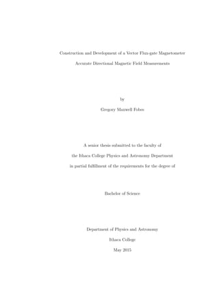
  • 1. Construction and Development of a Vector Flux-gate Magnetometer Accurate Directional Magnetic Field Measurements by Gregory Maxwell Fobes A senior thesis submitted to the faculty of the Ithaca College Physics and Astronomy Department in partial fulfillment of the requirements for the degree of Bachelor of Science Department of Physics and Astronomy Ithaca College May 2015
  • 2.
  • 3. Copyright c 2015 Gregory Maxwell Fobes All Rights Reserved
  • 4.
  • 5. ITHACA COLLEGE DEPARTMENT APPROVAL of a senior thesis submitted by Gregory fvlaxwell Fobes This tifesis has been reviewed by- the senior thesis conunittec and the department chair and is recognized as an Outstanding Senior Thesis Bruce ThompsnjdvisorDr. /1616,t%-t- L6e’t-R Dr. Michael “Bodhi” Rogers, Senior Thesis Corn- Date mittee Member Dr. Kellev D. Sullivaftenior Thesis Instructor J&/ Dr. ttke Keller. Chair. Department of Physics and Astronomy (lL]{ 15 Date v mat4 2ofr Date J I understand that my thesis will become part of the permanent print collection in the Ithaca College Department of Physics and Astronomy Society of Physics student room. A digital copy will also remain on file in the Department, and may be distributed within the Department or College for educational purposes. My signature below authorizes both the addition of my thesis to the student room collection and the distribution of my thesis for educational purposes. Mk, 1720/1; Al Date U A’1> 70/j_ Gregory Maxwell Fobes Date
  • 6.
  • 7. THE ABSTRACT OF THE THESIS OF Gregory Maxwell Fobes for the degree of Bachelor of Science in Physics submitted May 2015 Thesis Title: Construction and Development of a Vector Flux-gate Magnetometer Accurate Directional Magnetic Field Measurements This thesis report outlines the proper design, construction, and calibration of a high precision vector flux-gate magnetometer fit for geological application. The design implements a ferromagnetic ring core fit within a casing wound with a sensory coil. The alternating states of permeability within the ferromagnetic core act as the flux-gate control. Changes in the magnetic flux through the surrounding sensory coil induce an electromotive force output as a voltage. Several cores were tested to determine the best core material and geometry for a high precision and power e cient type flux-gate device. Complex analog circuitry is detailed for the proper drive current and output signal processing. Calibrations were made using a Helmholtz coil to test the external magnetic field strength versus the DC output voltage. Instrument specifications include: dynamic measurement range (±80 µT), accuracy of measurement (±100 nT), and resolution (±1.0 nT). The instrument that has been constructed operates as expected with specifications fit for geological application.
  • 8.
  • 9. ACKNOWLEDGMENTS A special thanks to Dr. Bruce G. Thompson for his guidance throughout the project, Dr. Michael Rogers for leading the archaeo-geophysics team and further application of magnetometry instruments at Ithaca College, editors Dr. Beth Ellen Clark Joseph and Dr. Kelley D. Sullivan for their constructive suggestions, student editors Rafael Ferrera, Stefan Gurgurich, and Charlie Woodward for their detailed analysis of the report and supportive comments, and also my family for their continued love and encouragement. I’d like to dedicate this report to my childhood friend, Christopher Montgomery, who dreamt of becoming a scientist one day.
  • 10.
  • 11. Contents 1 Project Background 1 1.1 Magnetic Field Generation and Fluctuation . . . . . . . . . . . . . . . . 1 1.2 Magnetic Prospecting of the Local Field . . . . . . . . . . . . . . . . . . 5 1.3 Magnetometry . . . . . . . . . . . . . . . . . . . . . . . . . . . . . . . . . 8 1.4 Flux-gate development . . . . . . . . . . . . . . . . . . . . . . . . . . . . 9 1.5 Basic Operational Mode . . . . . . . . . . . . . . . . . . . . . . . . . . . 10 2 Theoretical Outlook 13 2.1 Core Geometry and Magnetic field Generation . . . . . . . . . . . . . . . 14 2.2 Hysteresis of Ferromagnetic Materials . . . . . . . . . . . . . . . . . . . . 17 2.2.1 Power E ciency . . . . . . . . . . . . . . . . . . . . . . . . . . . 20 2.2.2 Saturation and Magnetic Permeability . . . . . . . . . . . . . . . 21 2.3 Flux-gate Operation . . . . . . . . . . . . . . . . . . . . . . . . . . . . . 25 2.4 Output Signal Demodulation . . . . . . . . . . . . . . . . . . . . . . . . . 27 2.5 Instrument Calibration . . . . . . . . . . . . . . . . . . . . . . . . . . . . 31 2.5.1 The Earth’s Magnetic Field . . . . . . . . . . . . . . . . . . . . . 31 2.5.2 Helmholtz Coil . . . . . . . . . . . . . . . . . . . . . . . . . . . . 32 3 Instrument Development and Construction 35 3.1 Measuring the Hysteresis of Ferrite . . . . . . . . . . . . . . . . . . . . . 35 3.2 Instrument Construction . . . . . . . . . . . . . . . . . . . . . . . . . . . 41 3.3 Electronic Signal Processing . . . . . . . . . . . . . . . . . . . . . . . . . 42 3.3.1 Primary Excitation . . . . . . . . . . . . . . . . . . . . . . . . . . 43 3.3.2 Sensory Output Demodulation . . . . . . . . . . . . . . . . . . . . 46 4 Measurement Calibration 49 4.1 Helmholtz Coil Design and Construction . . . . . . . . . . . . . . . . . . 49 4.2 Instrument Calibration . . . . . . . . . . . . . . . . . . . . . . . . . . . . 52 4.3 Instrument Stability and Noise Level . . . . . . . . . . . . . . . . . . . . 54 5 Data Analysis - Instrument Specifications 55 6 Discussion of Results 63 xi
  • 12. xii CONTENTS 7 Conclusion 71 References Cited 78
  • 13. List of Figures 1.1 Earth’s Magnetic Field . . . . . . . . . . . . . . . . . . . . . . . . . . . . 4 1.2 Daily Fluctuations - Sunrise - DC Magnetic Field Measurement . . . . . 7 2.1 Flux-gate Instrument Design . . . . . . . . . . . . . . . . . . . . . . . . . 15 2.2 Hysteresis (B-H) Curve for Suitable Flux Gate Core . . . . . . . . . . . . 18 2.3 Ferromagnetic Behavior during One Period of Drive Current . . . . . . . 21 2.4 Magnetic Permeability as Flux-Gate Control . . . . . . . . . . . . . . . . 23 2.5 Signal Processing . . . . . . . . . . . . . . . . . . . . . . . . . . . . . . . 29 2.6 Simplified Output Demodulation . . . . . . . . . . . . . . . . . . . . . . 30 2.7 Magnetic Field Production/Cancellation . . . . . . . . . . . . . . . . . . 34 3.1 Circuit Schematic for Measuring Material Hysteresis . . . . . . . . . . . . 36 3.2 Hysteresis Curves of Varying Voltage Drive and Frequency . . . . . . . . 39 3.3 Hysteresis Plot for Suitable Flux-gate Core Material . . . . . . . . . . . . 40 3.4 Primary Excitation Circuit . . . . . . . . . . . . . . . . . . . . . . . . . . 44 3.5 Sensory Demodulation Circuit . . . . . . . . . . . . . . . . . . . . . . . . 48 5.1 Hysteresis of Flux-gate Core . . . . . . . . . . . . . . . . . . . . . . . . . 56 5.2 Output Linear Response . . . . . . . . . . . . . . . . . . . . . . . . . . . 58 5.3 Accuracy of Measurement . . . . . . . . . . . . . . . . . . . . . . . . . . 59 5.4 Noise Response to Zero Field . . . . . . . . . . . . . . . . . . . . . . . . 62 6.1 Project Tools . . . . . . . . . . . . . . . . . . . . . . . . . . . . . . . . . 64 6.2 Application as a Navigational Instrument . . . . . . . . . . . . . . . . . . 68 xiii
  • 14.
  • 15. List of Tables 6.1 Geographic Magnetic Field Dependence - NOAA Data . . . . . . . . . . 70 xv
  • 16.
  • 17. Chapter 1 Project Background The objective of this report is the construction, calibration, and further development of a high precision flux-gate magnetometer. The design is that of a ferromagnetic ring toroid wrapped with induction windings and placed within a sensory coil casing. The principles of design, which outline the proper function of the instrument, rely on fundamental relationships between electricity and magnetism. Magnetometers of this design are used in a range of fields, including: astronomical research (Musmann, 2010; Acuna, n.d.), navigation (Garner, 1987; Lancaster, 1988), archaeology (Aspinall Arnold, 2008), and geology (B. G. Thompson, 1983; Kaufman, 2008; Edward Tarbuck, 1984; Sharma, 1986). Further calibration of the tuned output signal allows for a dynamic instrument, capable of measuring large planetary fields, sensing micro variations of localized anomalies at Earth’s surface, and characterizing many other electromagnetic sources in between. 1.1 Magnetic Field Generation and Fluctuation “Magnus magnes ipse est globus terrestris” The entire world behaves as a large magnet. 1
  • 18. 2 CHAPTER 1. PROJECT BACKGROUND William Gilbert (1600) Magnetic phenomena has long been a study of early peoples for a better understanding of it’s origin and natural occurrences. The application of lodestone’s unique material attractions and alignments dates back to 50 AD when these rocks were of use in global navigation (Blakely, 1995). Others sought to take measurement of the earth, atmosphere, and greater universe to characterize many planetary (otherwise universal) physical laws. Eventually the first total field magnetic measurement devices were constructed, capable of measuring a localized magnetic field strength. With rough field measurements and mathematical models in spherical harmonic analysis, Sir Karl Friedrich Gauss (1838) proved the existence and internal generation of the all-encompassing planetary magnetic field of the earth - commonly referred to as the geomagnetic field. There currently exists a geomagnetic model - the International Geomagnetic Refer- ence Field - which quantifies the varying three-dimensional components of the magnetic field strength at any position on the surface of the earth. The strength of the magnetic field, or rather the magnetic flux density of the directional magnetic field is dependent on the distance from the source of field generation at the center of the earth, with a general direction oriented from geographic south to north. The magnetic field strength is then independent of longitudinal position due to the symmetry of the earth, yet strongly dependent on latitude, and the altitude above sea level (Kaufman, 2008; U.S.G.S., 2015). Due to the magnitude and direction of the magnetic field, the needle of a magnetic com- pass orients itself north/south rather than east/west, forced to point in the same direction as the field lines when no other magnetic forces are present. The geomagnetic field is generated by the rotating liquid heavy metal electro-hydrodynamic outer core of the earth. Accepted theory states that the planet once existed as a red-hot liquid compound soup, allowing dense metals such as nickel and iron to sink to the center of the earth due to a strong gravitational force while outer layers began to stabilize and
  • 19. 1.1. MAGNETIC FIELD GENERATION AND FLUCTUATION 3 cool. To explain the large magnetic field surrounding the earth there must be a highly conductive (rich in free electrons) and pressurized rotating liquid iron-nickel outer core acting as a powerful magnetic field generator (Sharma, 1986). The concept is similar to the motion of electrons in a loop of wire - a current which generates a magnetic field flowing through the loop. The resulting magnetic field behavior is similar to that induced by a magnetic dipole with field lines emanating from geographic south (magnetic north) and bending around to point in the direction of north, much like the field pattern of a bar magnet. Measurements have shown that the geomagnetic field tends to change in both magni- tude and direction over time. In a short period of time, within 2000-5000 years, the field producing outer core may drift a complete 360 degrees relative to the rest of the outer planet. The study of paleomagnetism - geomagnetic shifts over great periods of time - yields convincing evidence of these changes as well as the frequent reversal of geomag- netic polarity approximately every ten-thousand years following a period of continual field degradation. Recent measurements have shown the magnetic field is now weakening and approaching another pole reversal. Currently, the geomagnetic poles are located at 78.8 North, 71.0 West in north-west Greenland and at 78.8 S, 109.0 East in Antarc- tica, displaced 11.5 West from the rotational axis (Sharma, 1986). At these points the vector field is oriented vertically to the surface of the earth, outward from the southern magnetic pole and inward to the North. At the location of the research laboratory, Ithaca College, Ithaca NY, the magnetic field has a total field strength of approximately 53,160 nT, with angle of inclination with respect to the ground at 68 deg (See Figure 1.2). In terms of components, the vertical and horizontal directional magnetic field in Ithaca NY is approximately 49,470 nT and 19,460 nT respectively, changing over time (National Center GeophysicalData, n.d.). The magnetic field emanating from within the earth has clear e↵ects on exterior at-
  • 20. 4 CHAPTER 1. PROJECT BACKGROUND N S mS mN Figure 1.1: Earth’s Magnetic Field (Schematic) This figure is a basic model of the earth as a giant magnetic field generator. The magnetic poles are represented in compar- ison with a bipolar bar magnet in which the attraction of a known north pole (as on a compass) denotes a magnetic south pole. These Geomagnetic poles are subject to change in magnitude and direction over time (Blakely, 1995).
  • 21. 1.2. MAGNETIC PROSPECTING OF THE LOCAL FIELD 5 mospheric conditions as well. The strong magnetic force fields generated within the plan- etary mass give rise to the magnetosphere. At this boundary the outermost geomagnetic flux densities interact with charged plasma from the sun to greatly distort the naturally occurring magnetic field strength. The field in this region serves an important role as the boundary for electromagnetic interaction, leading particles into the atmosphere above the polar regions and protecting the mass of the earth from the sun’s high-energy ra- diation (Blakely, 1995). The charged particles captured by the strong magnetic field in the northern and southern polar regions also surrenders a shimmering aurora that can be seen in the night sky (Knight, 2013). 1.2 Magnetic Prospecting of the Local Field In a geophysical setting, remote sensing capabilities of electromagnetic sensing devices act as an reliable method for investigation of the subterranean structures of earth. The proper sensing tool can often provide details of historical events which have been pre- served under a several layers of soil. A local magnetic sensing instrument allows for a study of (shallow/deep) surface soils and regional magnetic prospecting in geology and archaeology. For each experimental investigation, data collection, and further analysis beyond the basic sensing capabilities allows for understanding of past human activity and ongoing geological processes. The instrument of further study, the flux-gate magnetome- ter, provides a passive measurement technique in which the process of data collection does not disturb the sources that generate useful magnetic information (Aspinall Arnold, 2008). The source of magnetic contrast (e.g. historical artifacts and burials) may then remain in situ, not to be disturbed from its original position of rest. By recording an accurate measurement of the local, directional, and time dependent magnetic field strength, the source of small field variations and universal interactions
  • 22. 6 CHAPTER 1. PROJECT BACKGROUND are better understood. Much of ground based geophysical magnetic study is based upon earth’s material composition and past interactions. A good example of magnetic devia- tion may result from the uniform (magnetic) dipole alignments in ferrous materials due to the forces of a directional field - such as that of the earth. At the time that flowing lava vents began to cool below their Curie temperature, materials (rock formations) would solidify into fossilized compasses (Lancaster, 1988). The resultant local field which is stabilized and relatively uniform is then used as a reference point while prospecting for magnetic disturbances due to composition variation, temperature changes, fluid pockets, and other physical di↵erences within a larger material volume. Methods of electromag- netic sounding beyond that of simple magnetic sensing instrumentation has allowed for the geological analysis of the deep structure of earth. Deep crustal electromagnetic sounding performed using a large current loop in the Georgia Piedmont showed a sound- ing depth limit around 30 km into the earth’s crust where a layer of high conductivity began reducing accurate sensing abilities (B. G. Thompson, 1983). While searching for localized magnetic anomalies at earth’s surface, it is often small variations in the field readings (1-10 nT) that can yield clear and interesting results. While mapping a region for historical evidence of human influences there are often set- tlement patterns shown by magnetic contrast within the data. This information is used in understanding early social organizations and gives insight into the formation of human societies. One of the first archaeological features to be tested by magnetometry devices were clay kilns. In these structured holes, clay material high in iron oxide would be heated to a high thermoremanent magnetization, past their Curie point temperature. In such a state, the material becomes para-magnetic in which magnetic dipoles readily align with the directional field of the earth (Aspinall Arnold, 2008). Such materials would then provide a high magnetic field reading where this occurs. Another historical example, the
  • 23. 1.2. MAGNETIC PROSPECTING OF THE LOCAL FIELD 7 6:30am 1:30pm 52,900 52,905 52,910 52,915 52,920 52,925 52,930 Time of Day FieldStrength(nT) Figure 1.2: Daily Fluctuations - Sunrise - DC Magnetic Field Measurement: This figure shows the measurement of the geomagnetic field of the earth from a station- ary baseline magnetometer set approximately 1.5 m o↵ the ground, isolated from other field disturbances for a six hour period. This measurement was taken at Buttermilk Falls State Park in Ithaca, NY by a Geometrics Cesium Magnetometer provided by the Ithaca College Archaeogeophysics Laboratory. Measurements of the total magnetic field strength are taken in the nanoTesla range for this high-precision reliable field instrument with accuracy within 1 nT. The data reveals many micro-variations in the geomagnetic field and a notably stabilized diurnal field with patterned changes as the sun begins to rise.
  • 24. 8 CHAPTER 1. PROJECT BACKGROUND installation of a housing posts into the ground or any major disruptions to the natural subsurface layers changes the distribution of soil iron. After back-filled soil mixing occurs, this location will later provide a magnetic contrast with surrounding undisturbed soils, indicating some prior event had taken place (Rogers, 2003). Outside of measuring the variations in the geo-magnetic field and interior properties of the earth, a precision magnetic field measuring device also allows for the exploration of inter-planetary (space) characteristics and study of other rotational bodies similar to the earth. Flux-gate magnetometers are of major importance in outer space magnetic field measurements due to their simple design, low power consumption and vector re- sponse characteristics (Acuna, n.d.). Specification capabilities of the instrument can be characterized in a few categories: upper/lower measurement range, frequency dependent noise level, and zero drift time and temperature stability. The high-performance based operation of a flux-gate device will often depend on the specific source under investiga- tion. 1.3 Magnetometry Magnetic sensing instruments range in design and function in order to achieve the proper measurement of a specified electro-magnetic energy source. These di↵erent types of magnetometers include: proton-precession, optically-pumped (cesium vapor, rubid- ium, potassium), superconducting quantum interference devices (SQUIDs), Hall-E↵ect Probes, as well as varying styles of flux-gate magnetometers. Many of these survey devices - including the Hall-E↵ect probes, optically pumped, and proton precession mag- netometers - are scalar magnetometers, designed to measure the total field of the earth at a desired location. Although these instruments have proven their worth in technical surveys for a range of disciplines, they lack versatility. Hall sensors can be relatively
  • 25. 1.4. FLUX-GATE DEVELOPMENT 9 noisy with large temperature o↵sets, while proton precession devices require excessive power sources and time for measurement, and SQUIDs need applied coolant such as liq- uid nitrogen (Ripka Pavel, 1988). The ring-core flux-gate magnetometer, a directional field sensing vector measurement device, remains the best option for its low power con- sumption and reliable remote sensing capabilities. As compared to a total-field measurement device, the flux-gate sensor can detect a directional magnitude. Vector devices which measure a field strength and direction are of major importance in the case of source detection and field analysis. Flux-gate devices are the most precise magnetic field sensors in the mT to nT range. They have the capability of nT measurement stability and 0.1 nT resolution (Ripka Pavel, 1988). Currently there are two prominent measurement designs for high sensitivity flux-gate magnetometers, orthogonal and parallel. The parallel vector type flux-gate magnetometer is understood to have higher resolution and lower noise. Recent measurements (2009) were between 100 and 10 pTp HZ for DC fields or low frequency magnetic fields, taken by I. Sasada and H. Kashima at Kyushu University in Japan (Sasada & Kashima, 2009). This type of ring-core, vector measurement, is the design used for further testing in the performance of the flux-gate magnetometer. 1.4 Flux-gate development The study of electric and magnetic fields has laid the foreground for applied electronics and energy control technologies through the principal laws of electromagnetism. Practical applications of electromagnetic induction includes generators, transformers, navigational instruments, electrical motors, and high-e ciency switching power supplies. Similar principals allow for the function of a flux-gate magnetic sensor. The solid ferromagnetic ring-core flux-gate magnetometer was first introduced by
  • 26. 10 CHAPTER 1. PROJECT BACKGROUND William A. Geyger in 1961 using a AC voltage drive, similar to present practices (Acuna, n.d.). Since this time, many others have worked to improve the design for a wide range of application in scientific research and source detection. Major advancements in magnetic field sensing technology came during WWII when these magnetometers were used for airborne detection of submarines. Soon after the 1960’s, patterned magnetic measurements (high-low-high-low intensity) taken underwa- ter across the north-eastern pacific sea floor supported the theory of frequent reversal in the geomagnetic field. The iron-rich minerals within hot lava vents at the ocean floor had oriented themselves with the geomagnetic field before solidifying in position, keeping a detailed record of the total field polarity along continental plate boundaries (Edward Tar- buck, 1984). The same information strongly supported the process of sea floor spreading (Blakely, 1995). These discoveries, made using a flux-gate magnetometer, validated the theory of magnetic pole reversal and confirmed the theory of continental drift. 1.5 Basic Operational Mode This flux-gate magnetometer, the ICFG (Ithaca College Flux Gate) design relies on two coil windings, a primary around the toroid core used for magnetic excitation, and a large secondary loop fit around the core used as a field sensor. The sense windings rely on an induced electromotive force due to change in magnetic flux from which a voltage pulse measurement directly correlates to the vector magnitude of the magnetic field in the direction of instrument orientation. These flux-gate sensors fit a range of field- work applications: geophysical studies such as abrupt plate collisions below the earth’s observable surface as well as geophysical surveys, space exploration of other planetary magnetosphere, worldwide navigation systems (air, land, sea) and many other fields in between (Urusan, 2011; MJS Johnston, 1994; Blakely, 1995; Acuna, n.d.; Musmann, 2010;
  • 27. 1.5. BASIC OPERATIONAL MODE 11 Garner, 1987). The ICFG instrument uses a ferromagnetic material core - a compound of nickel, zinc, manganese, and primarily iron - with high permeability to channel magnetic field lines within the core and therefore the sensory coil. The core material is capable of manipulation by means of an induction winding which can alter the internal properties of the material such as the relative permeability by means of an induced magnetic field strength. Using an alternating drive current in the induction coil, rapid states of high- low permeability force changes in the external magnetic field strength channeled within the core. With the specific compound and proper resonant frequency input set, the best possible magnetic sensor can be constructed. In order to read the deviation in magnetic field, the sensory coil is wound about a rectangular casing and fit around the ferromagnetic toroid core, which is wrapped with primary drive windings. For the construction of a flux-gate magnetometer, proper methods of signal processing on the sensory output is necessary. As originally stated by W.A. Geyger, is important to design a circuit which may read the second harmonic of the output signal which has doubled in frequency relative to the drive frequency (Geyger, 1962). Thus the proper output demodulation and reading of these secondary harmonics can be used in finding the proportional magnitude of the externally applied magnetic field under investigation (Primdahl & Jensen, 1987; Araki, 1994; Garner, 1987). In reading this output, a con- stant or steadily changing magnetic field can be accurately measured. By altering the frequency, analog circuitry, and material of the toroid core, the goal is to improve the accuracy, power e ciency, noise, and frequency response of the ring-core flux-gate mag- netometer. The use of small “coin-sized,” electrically induced ferrous compound cores and internal magnetic amplification process allows for minimum excitation current (re- duced in comparison to other tested flux-gate cores) and makes the use of high excitation frequencies at and above 10 kHz possible (Geyger, 1962).
  • 28. 12 CHAPTER 1. PROJECT BACKGROUND
  • 29. Chapter 2 Theoretical Outlook The ICFG has a design based on the theory of electromagnetic induction and direc- tional magnetic field characteristics. The basic construction and further calibration of a high-precision flux-gate magnetometer is accomplished through the understanding of the prior work and scientific experience of others. Scientific authors such as M. Acuna, W. Geyger, F. Primdahl, and B.G. Thompson, make this project and the further theoretical advancement of applied physical instruments possible (Geyger, 1962; Primdahl & Jensen, 1987; Acuna, n.d.; B. G. Thompson, 1983). The model for this research is that of a ring-core geometry wrapped along its circu- lar path length with induction coils, then inserted within a sensory coil for directional magnetic field measurements (See Figure 2.1). The process begins with magnetic field generation in which a concentrated and oscillating magnetic field is generated within the ferromagnetic core using a high-frequency drive current in the induction coils. The toroid core is a specific material compound with geometry resembling that of a torus ring. These ferromagnetic compounds are often a mixture or iron, zinc, nickel, or other similar permeable metals. The high precision measurement capabilities of the flux-gate magnetometer relies on 13
  • 30. 14 CHAPTER 2. THEORETICAL OUTLOOK the physical core compound and its symmetrical geometry (Acuna, n.d.; Garner, 1987). The high sensitivity, low noise flux-gate device is constructed using small diameter toroid cores with a large flux capacity and small “L/d” ratio (inductance to diameter). The simple ring-core design is modeled after H. Aschenbrenner and G. Goubau (1936), revised by W. Geyger (1962) at White Oak U.S. Naval Laboratory, and improved upon over the past few decades with higher precision and low noise characteristics (Musmann, 2010). 2.1 Core Geometry and Magnetic field Generation Through a principal similar to that of a cylindrical solenoid, a concentrated magnetic field intensity is generated within a ring-shaped metal toroid when a current flows within the electrically conducting wire. The geometry of the toroid provides a continuous path for a uniform magnetic field to travel. The simple yet innovative design shown in Figure 2.1 allows for the concentration of magnetic intensity within the toroid along a con- tinuous closed path along with minimal electromagnetic interference (Francavilla T.L., 2013). The ring core design also presents the ability to use multiple sensory axes for the measurement of orthogonal vector components (Garner, 1987). For this report only one vector direction is measured and therefore one sensory coil is used. The primary windings around a circular path (enclosing the toroid within) provide a magnetic intensity much like a solenoid. The magnetic intensity (H) produced within the induction coil wrappings around the ring is understood by a simple relationship. ~H = ~IpN l (2.1) The magnetic intensity H is proportional to the primary current I, whereas the e↵ective path length l and number of coils N are held constant by design constraints (Francavilla T.L., 2013).
  • 31. 2.1. CORE GEOMETRY AND MAGNETIC FIELD GENERATION 15 Signal Generator +/- Sensory Casing Analog Signal M Ferrmagnetic Core Drive Winding Figure 2.1: Flux-gate Instrument Design The toroid core is wrapped completely around its circular path length with primary induction windings. This allows for the control of the magnetic field by means of a known current input. An alternating drive current provides a changing magnetic field and internal magnetization (M) in the core. The wound core is then fit into a casing wrapped with electrical conductive sensory windings. By Faraday’s Law, the sensory coil will output an electromotive force which is proportional to the change in magnetic field strength within the casing.
  • 32. 16 CHAPTER 2. THEORETICAL OUTLOOK The magnetic field strength ~B within a hollow (air-core) solenoid can be related to the induced magnetic intensity H, ~B = µ0 · ~H (2.2) In which µ0 is known as the permeability of free space with a value of 4⇡⇥10 7 Tm/A. This value is the proportionality constant needed to relate the induced magnetic intensity given in amps per meter (A/m) to the directional field strength given in Tesla (T) or Gauss (G). Introducing a medium – such as a ferromagnetic ring-core - within the primary windings will yield an alternate e↵ect due to inherent internal magnetization and relative permeability of the core. The total magnetic field strength (B) produced within the ferromagnetic core by the introduction of a magnetic intensity (H) is given by, ~B(t) = µ0( ~M(t) + ~H(t)) (2.3) The time dependent magnetization ~M(t) may vary in magnitude and direction due to the induced magnetic intensity ~H(t). This internal magnetic strength ranges from zero to Mmax, the material’s volume specific maximum magnetization strength, which is much larger than the induced magnetic intensity due to the small amount of current drive through the primary induction windings surrounding the core. This state of maximum magnetization and total dipole alignment is known as magnetic saturation. Therefore, when the core is in a state of magnetic saturation, or Mmax, the total field strength (B(t)) also approaches a maximum value. Equation 2.3 is the characteristic equation used in the analysis of ferromagnetic materials and further understood through the analysis of characteristic hysteresis curves.
  • 33. 2.2. HYSTERESIS OF FERROMAGNETIC MATERIALS 17 2.2 Hysteresis of Ferromagnetic Materials Ferromagnetic materials are iron-like material compounds that have the ability to be- have as permanent magnets. These materials, specifically because of their atomic struc- tures and quantum mechanical bonding properties, act unlike ordinary para-magnetic transition metals with weak magnetic interaction. Ferro-magnets have strong magnetic properties and require no externally applied field to retain internal magnetization ( ~M). The evident material magnetization in these particular elements is due to the inherent magnetic moment (spins) of free valence electrons. Under the influence of a directional force field, electron magnetic moments tend to align and create larger magnetic domains (Knight, 2013). In the element iron, this atomic characteristic is due to two unpaired electrons in the 3d orbital which are free to interact with other free electrons of similar atoms. The atomic structure of these iron-like compounds is that of strong magnetic dipoles, active due to the spin of unpaired electrons (Gri ths, 1989; Aspinall Arnold, 2008). More specifically, the paired electrons within the ‘s’ orbitals act to shield the (magnetic) interaction between two ‘d’ shell electrons of di↵erent atoms (Kanamori, 1963). The forces of magnetism caused by these electrons are then superposed, creating a large magnetic force relative to other materials. The analysis of the rapid increase, decrease, and reversal of the magnetic field caused by the high frequency drive current through the coil windings provides information re- garding the physical properties of the experimental ferromagnetic core. By plotting the total directional magnetic field strength ( ~B(t)) as a function of the magnetic intensity ( ~H(t)) properties the core material can be obtained in the form of a hysteresis (Garner, 1987; Francavilla T.L., 2013). An example of a hysteresis loop which was measured in the laboratory is shown in figure 2.2. At the heart of a high precision ring-core flux-gate magnetometer is the magnetically
  • 34. 18 CHAPTER 2. THEORETICAL OUTLOOK −600 −400 −200 0 200 400 600 −2.5 −2 −1.5 −1 −0.5 0 0.5 1 1.5 2 2.5 x 10 −5 H(A/m) B(T) C mS mR Figure 2.2: Hysteresis (B-H) Curve for Suitable Flux Gate Core This is the char- acteristic hysteresis curve that has been measured for the given flux-gate core material at a drive frequency of 300Hz and peak to peak voltage of 37.0 V. The plot shows the total magnetic field strength versus the magnetic intensity (H) or the proportional drive cur- rent (I) within the ferromagnetic ring core. Distinct levels of saturation (mS), coercivity (C), and residual magnetism (mR) are shown. susceptible core material acting as a path over which magnetic field lines can travel. The permeability and saturation levels of the induced magnetic core are two important parameters when choosing a high precision flux-gate core. The plot in Figure 2.2 shows the non-linear relationship between magnetic field in- tensity ~H(t) and magnetic field strength ~B(t) for one full period of oscillating input frequency. With large enough current and proportionally generated magnetic intensity, the core material is forced into a state of magnetic saturation - when the internal mag- netic dipoles of the material reach maximum alignment. This alignment and permeability cuto↵ happens twice, once in each direction for each period of drive current. The near-
  • 35. 2.2. HYSTERESIS OF FERROMAGNETIC MATERIALS 19 vertical linear lines of the hysteresis curve represent regions of high permeability before and after the core has been driven into magnetic saturation. There is a well known procedure for testing ferrous compounds used for applications such as flux-gate core materials. A hysteresis loop shows the magnetization over one period of alternating input current. The term hysteresis simply implies a lagging time dependence for the internal state of the material core under the influence of a changing magnetic field intensity. The path of hysteresis (see Figure 2.2) begins at the origin moving directly right as current is sent through the primary coils to induce a magnetic intensity. In the analysis of ferromagnetic cores a secondary coil is wrapped around the toroid just as the primary coil in order to sense a changing magnetic flux in the form of an electromotive force. As the magnetic intensity increases, the magnetization of the core material soon follows and reaches its maximum value at the saturation flux density (labeled mS in figure 2.2). At maximum field strength, the once high-permeable core changes state - the flux-gate closes. The change in relative permeability occurs when the material has reached maximum magnetization an has no further potential to become magnetized. As the current then drops to zero the magnetic intensity also drops to zero, however, some residual magnetism remains (mR). The coercivity levels (C) mark the resistance to magnetization and the reversal force needed to remove the remnant magnetism. Many characteristics including those previously stated must be taken into account when choosing the proper core for the flux-gate instrument. To measure the total field ( ~B) within the toroid, a sensory coil is wound isolated from, but similar in fashion, to the primary winding. The primary and secondary windings are wound using a simple transformer-like configuration around the core. Faraday’s Law of electromagnetic induction gives the electro-motive force generated in a coil of wire if the magnetic field passing through the region of coils is changing (Knight, 2013). By
  • 36. 20 CHAPTER 2. THEORETICAL OUTLOOK integrating the output voltage (emf), the magnetic field (B) within the core at any time (t) during the cycle of the periodic driving current is given by, B(t) = 1 N2A Z t 0 Vout(t)dt + B(0) (2.4) In which N2 represents the number of secondary turns, A the cross-sectional area of the toroid core, and Vout the measured output voltage from the sensory winding. The addition of the initial field strength B(0) is necessary and shows that the internal state of these materials is time dependent and that the recent history of states must be accounted for. 2.2.1 Power E ciency The small magnetic intensity required for magnetic saturation - complete magnetic dipole alignment - allows for high frequency input as well as low power consumption while mak- ing high precision measurements. The energy, or physical work, required to reorient the material domains within the ferrite core is also depicted by the characteristic hysteresis curve. The area of the plot in the figure shown represents the work dissipated (W), or rather the energy lost during each period of alternating input current (Francavilla T.L., 2013). The loss of energy, in joules per cycle, can be determined from measured quantities of output voltage and primary current over a single period of the drive frequency. W = Z T 0 Vout(t)IP (t)dt (2.5) For a low power, stable, and reliable flux-gate core the hysteresis curve must be slim, representing low energy loss and high performance. This energy consumption is important when distinguishing between material cores and in applications for e cient power transformers. Low power consumption instruments are also in high demand for
  • 37. 2.2.2 Saturation and Magnetic Permeability 21 Figure 2.3: Ferromagnetic Behavior during One Period of Drive Current Shown is the simplification of how magnetic domains (millions of atomic dipoles) are reoriented due to the concentration of a magnetic field within the primary induction coils. The ferromagnetic material acts as a transforming permanent magnet in which the alternat- ing (current) magnetic intensity drives the material into alternating states of magnetic saturation Mmax in opposite directions. Note that the changing internal state of the core also influences the relative permeability. The complete cycle is the same of that shown by the hysteresis curve in Figure 2.2. many applications, for example space exploration where power is limited. 2.2.2 Saturation and Magnetic Permeability It takes energy to introduce a force that has the ability to reorient domains within a material. Under the influence of a large alternating current, the magnetic intensity induced within the toroid forces atomic dipoles within the core to align, creating a time dependent net magnetization ~M(t). If enough driving current is applied through the induction winding, the core will be forced into magnetic saturation. In this state, internal
  • 38. 22 CHAPTER 2. THEORETICAL OUTLOOK magnetization reaches a maximum value for the specific material volume. The e↵ect of internal magnetic dipole alignment is a physical reaction to a magnetic force. Other than the reversal of electrical induction, the only relief for ferromagnetic dipole alignments are temperatures above the characteristic Curie temperature or another physical force. For a large enough alternating drive current magnetic saturation will happen twice, once in each direction during each period of input frequency. At points of saturation the relative permeability of the core (µ/µ0) drops to one as magnetic dipoles align in a unified direction. At this point the magnetic flux lines are expelled out of the core, producing a rapid change in magnetic field strength within the core. The literal open-close gate action allowance of magnetic flux through the core is accomplished by alternating between states of magnetic saturation, changing the per- meability of the ferromagnetic core. To drive the core into magnetic saturation, a high frequency alternating square-wave is applied to the primary excitation winding. The changing saturation of the core acts as a gating mechanism, allowing and resisting the flow of an external magnetic field through the core material. When the core is saturated it has low permeability, expelling what external field lines (flux) are contained within the core. Otherwise, when the core is unsaturated, permeability rises to relatively high max- imum value and magnetic field lines are drawn within (See Figure 2.7). In this state of high permeability, while the core is not saturated, magnetic dipoles have not yet reached maximum alignment and the material acts as a low impedance path for magnetic field lines to pass through (Garner, 1987). The magnetic field (B) within a material and the magnetic intensity (H) are related by the equation, ~B = µR · µ0 · ~H (2.6) The relative permeability µR representing the e↵ect of the introduced medium (core
  • 39. 2.2.2 Saturation and Magnetic Permeability 23 Saturated Core Unsaturated Core Figure 2.4: Magnetic Permeability as Flux-Gate Control For a high frequency drive current the core material rapidly alternates between these states of low permeability (magnetic saturation) and high permeability.
  • 40. 24 CHAPTER 2. THEORETICAL OUTLOOK material) relative to the permeability µ0 of free space. In the core material the relative permeability changes depend on the internal state and magnetic dipole interactions. For ferromagnetic compounds with high relative permeability (µR >> 1) the magnetic intensity (H) generates the total field (B) by the addition of a net internal magnetization. The relative permeability is given by, µR = µm µ0 (2.7) The material specific permeability µm is better known as the volume specific magnetic susceptibility, derived from the material magnetization - the total magnetic moment of the sample divided by its volume (Aspinall Arnold, 2008). The relative permeability range is therefore dependent on the material compound. In the flux-gate core material, changes in permeability occur due to the influence of an alternating magnetic intensity which forces a change in the internal magnetization. The true use of the material specific permeability is seen in the relationship between the net magnetization of a material (M) and the electrically induced magnetic intensity (H). B = µmH (2.8) The characteristic property of these ferrous compounds used in flux-gate cores is stable magnetization (M) as well as high relative permeability (µr) at coercivity levels when magnetic domains are disoriented (See Figure 2.2). The permeability of the ferromagnetic core is dependent on the time dependent state of internal magnetization. Permeability characterizes a material’s ability to channel the flow of an external magnetic intensity. The concept is much like a magnetic conductivity - with high permeability, the magnetic field will move through (be absorbed by) the core to induce further magnetization. For the
  • 41. 2.3. FLUX-GATE OPERATION 25 flux gate core, permeability is a measure of the materials potential to become magnetized. 2.3 Flux-gate Operation The diagram shown in Figure 2.1 is a simple representation of the design used to mea- sure the magnetic field strength in one direction through flux-gate control. The ring-core ferromagnetic toroid is wrapped tight with wire and inserted into the sensory casing. The signal generator then inputs a large enough alternating current (through the pri- mary windings) to saturate the toroid with maximum internal magnetization (M) twice, once in opposing directions for each periodic cycle. At proper resonant frequencies (ap- proximately 30 kHz) the toroid ring becomes sensitive to any external magnetic field when alternating between states of magnetic saturation. When the core is driven into saturation by the induced magnetic intensity, the permeability of the core drops to that of free space (µ0) and external field lines are expelled from the core. While the core is alternating between states of magnetic saturation the permeability is high and magnetic field lines pass though the core. By means of a sensory coil, a rapid change in magnetic flux due to an external field is output as a voltage (electro-motive force). The output is then calibrated to an accurate measurement of the directional field strength within a defined region. At the instant between states of magnetic saturation, the ferromagnetic core material permeability (µm) is high and a surrounding magnetic field is channeled within the toroid core (See Figure 2.4). The resulting e↵ect is then an increased flow of magnetic flux through the sensory coil winding over the period of high permeability. The drive cycle then continues to saturate the core in which the material permeability drops and magnetic flux is expelled from the core. By Faraday’s Law, it is these rapid changes in magnetic field strength through the sensory coils (flux allowance and flux repulsion) that induces
  • 42. 26 CHAPTER 2. THEORETICAL OUTLOOK an electro-motive force proportional to the external magnetic field. " = | d dt |Ns (2.9) By implementing a sensory coil around the toroid, the changing magnetic flux chan- neled through the permeable core can be recorded and calibrated to fit a direct field measurement. For the theoretical calculation, Ns represents the number of wire turns around the sensory casing and d represents the changing magnetic flux through the looping of wire. The flux through the coil is the magnetic field strength through a specified region and is a scalar quantity. m = ~A · ~B (2.10) The variable ~A represents the e↵ective area within the sensory coils with a direction normal to the area - along the center axis of the coils. For the application of a flux-gate sensor with fixed rectangular area (A) and number of coil turns (Ns) the change in flux is given by, d dt = dB dt ANs (2.11) Therefore an output voltage (pulse) is derived from the electromotive-force as, Vout = NsA dB dt (2.12) The important relationship shown here is that the output of the sensory coil gives a voltage value proportional to the changing magnetic flux passing through the sensory casing (Aspinall Arnold, 2008). Given Lenz’s Law, electromagnetic nature recoils from
  • 43. 2.4. OUTPUT SIGNAL DEMODULATION 27 a forced change in flux (restores the original state) and therefore produces an electrical force, or current, in the opposing direction to cancel the unexpected change (Gri ths, 1989). As flux rapidly increases a negative current (backwards flow) pulse is sent through the sense winding, whereas a decrease in flux density would produce a positive current flow. Over one full period of input current, this cycle of rapid flux increase and decrease yields four voltage measurements, two sets of positive then negative output pulses. There- fore analysis for each signal pulse is done on the second harmonic, or rather twice the input frequency. With a high frequency input and stabilized output, the voltage pulse signals are demodulated and thereafter averaged for a reliable direct field measurement in Tesla. 2.4 Output Signal Demodulation The raw sensor output due to an external field is a set of oscillating positive/negative pulses. For each period of drive frequency the core will saturate twice and four flux changes will be measured – flux out at positive current peak followed by flux in before the negative current peak, and then repeated. The function of the electronic circuity is the proper excitation input and output demodulation of the signal. The main focus for measurement is to invert (every other) voltage pulse to align a signal such that all are positive (forward) flowing current pulses. Then a baseline average over a short period of time is a much more precise way of field measurement. The system works using two 4013B CMOS dual flip-flops (think of them as logic NOT gates or inverters) as well as two 4066 bilateral (high/low) switches. The regulation of the signal is based on the output frequency, tuned to the 2nd harmonic of the drive frequency using these circuit components and acts to operate the switches in a fashion that will convert the wave form to a forward biased high frequency repeating pulse. After this demodulation of the
  • 44. 28 CHAPTER 2. THEORETICAL OUTLOOK wave form the signal is fed to an averaging amplifier. At this point the repeating pulses are averaged to obtain a direct voltage output. The polarity (+/ ) of the output value also indicates field direction (See the next Chapter Methods for the complete circuit diagram). The acquired DC output voltage will then correspond (be proportional) to the lo- calized external magnetic field strength with the slope of the Field Strength vs. Output Voltage graph giving the necessary conversion factor. Keep in mind that the instrument orientation is extremely important for single directional field measurements - only the field traveling through the sensory coil is accounted for. Figure 2.5 shows the demodulation of the output signal occurs at twice the drive frequency. Therefore, analysis of the output waveform is tuned to the second harmonic of the drive current frequency, acting to induce a magnetic intensity withing the primary coils around the ferromagnetic core. fout = 2finput (2.13) The use of a resonant circuit is key in working with high frequency excitation and response. The role of an LC circuit (inductor and capacitor) is to act as a band-pass filter allowing only a set range of signal frequencies to exist. The idea is that a set value of inductance (L) and capacitance (C) provide a periodic time behavior in which the two components exchange energies. The primary windings around the toroid impose a large impedance and therefore must be coupled with a specific parallel capacitance to ensure proper output at the second harmonic of the drive frequency. The theoretical equation for the characteristic resonant frequency is derived from Ohm’s Law and the concept of electrical impedance (resistance of non-resistors).
  • 45. 2.4. OUTPUT SIGNAL DEMODULATION 29 L Out R D A In Figure 2.5: Signal Processing This diagram depicts the basic wave forms needed in the proper function of the high-precision vector flux-gate magnetometer. In represents the high frequency square-wave input used to e↵ectively drive the core into alternating states of saturation.L represents the primary winding loaded by the ferromagnetic core. Each asterisk marks the point of core saturation and drop in permeability. Out represents the output from the sensory coil when there is a clear and direct external magnetic field present. Each voltage blip represents a large change in flux during states of switching permeability (gate-action). R represents a regulating square wave at twice the input frequency (out of phase) which works with the two electronic 4066 bilateral switches and two NOT gates to demodulate the output wave form for maximum accuracy. D is then the demodulated (fixed) signal in which sub-zero pulses have been flipped to match their partnering positive voltage pulses. A would then represent the output from an averaging amplifier, a direct measurement proportional to the directional magnetic field strength being measured.
  • 46. 30 CHAPTER 2. THEORETICAL OUTLOOK Sensor IC3-555 Regulator 4066 4066Out R D R* Out* A Figure 2.6: Simplified Output Demodulation (Schematic) This circuit outlines a major simplification of electrical components and necessary logic to properly interpret the output waveform from the sense winding. (See Fig. 2.5) f0 = 1 2⇡ p LC (2.14) The resonant circuit has the ability to amplify signals at the second harmonic of the drive frequency while ignoring all other noise in the output signal. The input frequency is set by the 4047B astable mode timer using a known value resistor and capacitor combination. The use of a high frequency square wave input to force alternating states of core saturation provides the ability of measuring the magnetic field strength thousands of times each second, therefore allowing a high precision voltage response output from the sensory circuit.
  • 47. 2.5. INSTRUMENT CALIBRATION 31 2.5 Instrument Calibration 2.5.1 The Earth’s Magnetic Field This report is built around the theory that a magnetic field exists at all points in space, with larger flux densities measured surrounding a magnetic source. Likewise, the earth’s naturally occurring and known magnetic field strength is dependent on geographic loca- tion, altitude above sea level, and time. The internal magnetic generating source of the earth produces a large-scale yet diminishing long-range field strength, directed at a steep angle as latitudes increase from the planet’s equatorial line. By finding the approximate magnetic field strength with other reliable devices and with proper theoretical under- standing, the accuracy of a magnetometer’s measurement can be adjusted for any micro variations due to time and location. A reliable magnetic reading is used as a baseline output value to calibrate the magnetometer by testing the accuracy and stability for precision direct field measurements. Although the geo-magnetic field is all-encompassing to the planet (See Figure 1.1) it varies greatly with location and time. At the location of assembly and experimenta- tion, Ithaca College, Ithaca NY, the present total Earth’s Magnetic field strength has a theoretical value of 49,579.3 nT (at sea level, in contrast with Figure 1.2) changing at a rate of -141.1 nT per year. The field also has an angle of declination at approximately 12 10 W, changing by 0 10 E per year (National Center GeophysicalData, n.d.). Measure- ments taken from within the laboratory environment may di↵er from these theoretical values by a considerable amount due to magnetic noise from electronics and surrounding magnetically responsive materials.
  • 48. 32 CHAPTER 2. THEORETICAL OUTLOOK 2.5.2 Helmholtz Coil This vector type of magnetometer works to measure magnetic field strength in one di- rection only. The measured magnetic field strength ( ~Bi) through the sensory coil will depend on the orientation of the flux-gate apparatus relative to the earth’s magnetic field. ~Bi = ~Bcos✓ (2.15) Where ✓ is the angle from the axis of measurement ( ~A) to the direction of maximum field strength. To begin proper calibration of the flux-gate magnetometer, a known magnetic field is generated. To test the ICFG device the earth’s field is first nullified to provide a zero baseline measurement. To produce a known external magnetic field for testing, a Helmholtz coil is used (See Figure 2.7). The Helmholtz coil is designed from two large coil wrappings separated by one radial distance from which a theoretically known magnetic field strength can be produced. The induced magnetic field is dependent on the geometry of the coils and amount of electrical current flowing through the two coil loops. This localized field strength produced between the two axial aligned coils can be used to further test the flux-gate magnetometer device at a range of field strengths, input frequencies, and positions relative to the coils. This design grants the ability to cancel the naturally occurring magnetic field strength of the earth through proper field generation and instrument orientation. This is done by aligning the Helmholtz coil axis with the known magnetic field direction and generating a field equal but opposite to the known magnitude at that location. The neutralization or cancellation of a regional magnetic field allows for proper calibration and noise char- acterization of the flux-gate sensor when no external magnetic field strength is applied.
  • 49. 2.5.2 Helmholtz Coil 33 From the Biot-Savart law for the magnetic field along a steady line of electric cur- rent, the induced magnetic field at the center of the Helmholtz coil is derived using the superposition of charges along the two coil windings (Gri ths, 1989). BT = ✓ 4 5 ◆3 2 · µ0NI R (2.16) In which µ0 is the permeability of free space (air), N is the number of turns for each of the two coils, I is the direct current value, and R is the radial distance of each coil. In proper design and calibration the experimental goal is to construct a reliable DC field measurement instrument. Although many magnetic sources vary with time and have characteristic frequencies, the instrument is set to output the directional magnitude of a stabilized field strength. Through the following methods of research the overall accuracy and noise characteristics of the measurement device will be determined.
  • 50. 34 CHAPTER 2. THEORETICAL OUTLOOK Figure 2.7: Magnetic Field Production/Cancellation This figure is a simple design for the Helmholtz Coil in which two large coils of wire are spread one radial distance apart on the same axis to allow for uni-directional magnetic field generation. The basic electromagnetic theory of the Biot-Savart Law (Gri ths, 1989; Jian Wang, 2002) is used alongside other field sensing instruments which were available through the Ithaca College research laboratory to determine the approximate value of the induced field at the center of the two coils. The device is used to produce a wide range of magnetic field strengths and also to cancel the naturally changing and localized magnetic field strength at earth’s surface in order to test the flux-gate instrument.
  • 51. Chapter 3 Instrument Development and Construction The objective of this thesis report is the proper construction and calibration of a high precision vector flux-gate magnetometer. A major part of the project was conducted under the guidance of Dr. Bruce G. Thompson in the electronics research laboratory at Ithaca College. 3.1 Measuring the Hysteresis of Ferrite The design of the ICFG was specialized to fit a particular ferrite core of high interest due to its small dimensions and material characteristics. The final core material selected is not explicitly known, however it is of the same type used by the Voyager Spacecraft (1977) and presumed to be of high quality in ferromagnetic response (Thompson, 2014). Further tests have confirmed this assumption. The material core compound is a major limiting factor in the simple design of a high precision flux-gate sensor. Similar coin-sized toroid cores are used as passive inductors for AC filtering with the ability to temporarily store 35
  • 52. 36 CHAPTER 3. INSTRUMENT DEVELOPMENT AND CONSTRUCTION Rin Pw Sw VR AC Source M B H Vout Figure 3.1: Circuit Schematic for Measuring Material Hysteresis Using a transformer-like configuration, primary coils (PW ) are wound to induce a magnetic in- tensity (H) within the core while secondary coils (SW ) are wound to measure the change in total magnetic field (B) as a function of time in large part due to the internal magne- tization strength (M). The alternating current source measured across the resistor by VR changed in magnitude, frequency, and waveform, as specific material cores were tested. Vout provides a measurement on the changing magnetic field strength (B) within the ring core. electrical energy in the form of a magnetic field. The primary coil wrapped completely around the path length of the ferromagnetic core forms a similar (high-grade) type of inductor in which the magnetic field is controlled and well understood. In the process of flux-gate core selection, di↵erent geometric and ferromagnetic ma- terial cores were tested for comparison. A secondary coil is wrapped around the toriod core similar to the primary winding in a transformer configuration (See Figure 3.1). The secondary coil allows for the measurement of alternating magnetic field strength within the toroid as a function of the induced magnetic intensity. This design is unlike the sensory coil used in the flux-gate magnetometer which is wound about a casing instead. To collect the data needed to produce material hysteresis curves a Tektronics Oscil- loscope was utilized to record the alternating input current (Channel 1) across a resistor (VR) as well as the output voltage (Vout) (Channel 2) as a function of time. The data
  • 53. 3.1. MEASURING THE HYSTERESIS OF FERRITE 37 sets were first stored in a (CSV) Microsoft Excel file, then used for further mathematical analysis by means of MATLAB computer software (MATLAB, 2012). The current is calculated from the measurement of VR which is then used to determine the magnetic field intensity (H) within the toroid. The measurement of Vout is used to calculate the resulting magnetic field strength (B) as well as the energy dissipated for each cycle as material magnetic domains were forced into and out of alignment. Key features of a characteristic hysteresis curve fit for a flux-gate magnetometer core include regions of high permeability to allow the flow of an external field within the core, low coercivity representing small magnetic restoring forces, as well as distinct saturation flux densities, indicating that maximum internal magnetization is achieved (See Figure 3.3). Saturation flux density is a measure of the maximum magnetic induction possible for a specific core, an intrinsic physical property (Francavilla T.L., 2013; Geyger, 1962). For instruments with large measurement range and low power consumption, the proper drive amplitude must be sought in order to ensure magnetic saturation in the core is achieved with high e ciency. It takes energy to reorient the magnetic domains within the solid-state ferromagnetic core. For magnetometers of low power consumption, it is best that the magnetic dipoles can be re-oriented and maximum magnetization reached with little work done. The work to force the material into magnetization in each direction, or rather the energy dissipated per cycle, is proportional to the area inside of the material’s hysteresis curve when distinct saturation levels are reached and a closed loop is formed. The hysteresis curve depicting the total field (B) relative to the drive current (I) forming a complete closed loop gives the total work in terms of the voltage output and current input (recall that electrical power is the product of voltage and current given in joules per second). By taking the total sum, or the integration, of this product over one period of drive current the total hysteresis loss per unit volume, or dissipated work measured in joules is determined for
  • 54. 38 CHAPTER 3. INSTRUMENT DEVELOPMENT AND CONSTRUCTION each drive cycle. An initial material toroid was selected to study its hysteresis curve and internal mag- netic behavior. The material compound was that of iron manganese zinc, determined by a FairRite Products data sheet. Geometric verification was established using a set of digital calipers with dimensions of outer diameter, inner diameter, and thickness: 25.40 mm x 15.50 mm x 8.15 mm which matched the manufacturer’s specifications. For the first material analysis (Test Ferrite 1) 80 ± 1 primary excitation windings and 82 ± 1 secondary sense windings were wound by hand about the path length of the toroid. To drive the circuit a 4012A BK Presision sweep/function frequency generator was used. Any further amplification needed to saturate the core was then provided by two LF411-N operational amplifiers allowing a drive of 25 Vpp (voltage peak to peak) or a BAA 500 TIRA power amplifier to reach a drive amplitude of 37 Vpp. The resulting hysteresis plots are shown (Figure 3.2). By simple inspection it can be determined that this material is not fit for a high-precision flux-gate magnetometer. The specific hys- teresis curves show the toroid lacks distinct saturation levels at large drive voltages with a relative permeability that is low in comparison to other ferrous materials. Material saturation occurs during maximum dipole alignment, when the internal core reaches a steady (constant) total magnetic field strength. While the vertical axis of the hysteresis plot measures total field strength this occurrence is represented as a near horizontal line at the top and bottom of the curve. The path of hysteresis occurs in such a way because the internal magnetization (M) provides the large part of the total field strength (B). The magnetic intensity (H) driven by the induction coils acts primarily to lead the e↵ects of internal magnetization, continuously altering the states of the core. According to the computer (MATLAB) approximation, the energy dissipated per cycle is less at higher frequencies for this particular core. A second material core was then selected to find a better core for a low-power, high
  • 55. 3.1. MEASURING THE HYSTERESIS OF FERRITE 39 −500 0 500 −3 −2 −1 0 1 2 3 x 10 −5 Test Ferrite − 15Vpp at 100Hz H (A/m) B(T) −500 0 500 −3 −2 −1 0 1 2 3 x 10 −5 Test Ferrite − 25Vpp at 100Hz H (A/m) B(T) −500 0 500 −3 −2 −1 0 1 2 3 x 10 −5 Test Ferrite − 37Vpp at 300Hz H (A/m) B(T) −500 0 500 −3 −2 −1 0 1 2 3 x 10 −5 Test Ferrite − 37Vpp at 100Hz H (A/m) B(T) W = 112µJ W = 108µ J W = ??? W = 85µJ Figure 3.2: Hysteresis Curves of Varying Voltage Drive and Frequency These plots represent the initial hysteresis analysis for a single toroid core. The plots represent the changing inputs of drive current amplitude and frequency for a sinusoidal waveform. At 15 Vpp 100 Hz the core was not driven into saturation, the energy dissipated is not calculated due to the small overlapping loops at maximum field strength (B). At 25 Vpp at 100 Hz a hysteresis loop is depicted however the clear saturation levels are still not achieved. Although both plots (100 Hz and 300 Hz) at 37 Vpp show hysteresis curves with saturation levels, the work loss is much higher than preferred. Also, the relative permeability represented by the transitions between saturation levels should be vertical, representing rapid flux changes in the core.
  • 56. 40 CHAPTER 3. INSTRUMENT DEVELOPMENT AND CONSTRUCTION −500 −400 −300 −200 −100 0 100 200 300 400 500 −8 −6 −4 −2 0 2 4 6 8 x 10 −7 H(A/m) B(T) W = 1.2µ J Figure 3.3: Hysteresis Plot for Suitable Flux-gate Core Material This plot repre- sents a much more suitable material toroid for use in flux-gate instrumentation relative to that shown in Figure 3.2. It is fabricated to operate at high frequency drive currents ( +20 kHz) as opposed to the previous low frequency core. Scaling di↵erences along the y-axis yield a much smaller enclosed loop than that of the previous hysteresis analysis, meaning less work is required to saturate this material core each cycle. With a drive of 20 Vpp and frequency of 20 kHz the curve shows excellent characteristic properties for a flux-gate core material. Horizontal levels represent the distinct saturation levels or maximum magnetization in each direction. The vertical transitions depict periods of high permeability within the core, when external magnetic flux is drawn in.
  • 57. 3.2. INSTRUMENT CONSTRUCTION 41 precision flux-gate magnetometer. The material compound is unknown but measured by dial calipers with dimensions of outer diameter, inner diameter, and thickness: 18.90 mm ⇥ 14.54 mm ⇥ 3.00 mm. The resulting hysteresis curve is shown (figure 3.3). In this case there were approximately 141±2 primary excitation windings and 89±1 secondary sense windings. Further testing of di↵erent material cores determined that with clear regions of permeability and levels of saturation at a drive voltage of 20 volts peak to peak and 20 kHz, this second core is a major improvement. The ability of the core material to perform at high frequencies is important for pre- cision instrumentation. A high frequency drive current (greater than 10 kHz) allows the core material to cycle through the hysteresis cycle of saturation and high relative permeability more rapidly. This e↵ect yields more flux induced output sensory pulses and therefore more field measurements per unit of time. Although the instrument is set to measure direct field characteristics, more measurements per second provides higher accuracy for changing magnetic field strengths. 3.2 Instrument Construction The overall dimensions of the instrument body and sensory casing were determined by the dimensions of the best suited material toroid for use as a flux-gate magnetometer core. Accurate measurements are made using dial calipers allow for the calculation of the e↵ective path length of the toroid needed for the previous calculation of the induced magnetic intensity as well as the proper dimensions for a tight fit sensory casing. The sensory casing was custom-designed using AutoCAD design software to allow for a single sensory winding around the body of the toroid (AutoCAD, 2014). To construct the case a Makerbot Replicator2 3D Printer was utilized (MakerBot, 2014). The print was made of a non-toxic corn based PLA (plastic) filament which allowed for minimal
  • 58. 42 CHAPTER 3. INSTRUMENT DEVELOPMENT AND CONSTRUCTION magnetic interference. Multiple sensory casings of similar design were printed to allow for di↵erent numbers of coil turns on each. Although the toroid used in the instrument application was previously wound by the manufacturer with primary excitation windings, all sensory windings about the casing were wound by hand with 32 gauge wire. The first sensory casing has approximately 70 ± 1 coil turns while the second casing of similar design has approximately 200 ± 2. The inductance of the primary coil and secondary coils was determined with a BK Precision 879B LCR meter at 1 kHz. The inductance measurements of the excitation coil and first sensory casing were approximately 3.20 mH and 39.40 µH respectively. With the core placed within the first sensory casing the inductance of the sensory casing then increased to 77.5 µH. Likewise, a second sensory casing was measured with inductance of 405.5 µH with the core in place. These inductance values are important for proper use in electronic circuitry for primary coil excitation and output signal demodulation. 3.3 Electronic Signal Processing List of electronic components Excitation Circuit: - CD4047 astable/monostable multivibrator timer (RC set) - CD4013 CMOS Dual D-type Flip-flop - PN2907A PNP Bipolar Transistor - MPS2222A NPN Bipolar Transistor - IN5282 Diode (4) - 4.0mH Inductor (Choke) - Specified Values: Resistors, Capacitors (polarized/tantalum and non-polarized) Sensory Output Circuit:
  • 59. 3.3.1 Primary Excitation 43 - CD4066B Quad Bilateral Switch (2) - OP227G Operational Amplifier (3) - Specified Values: Resistors, Capacitors (non-polarized) Other Equipment: Power Supply, Oscilloscope, Multi-meter, BNC cables, bread- board, wires, etc. 3.3.1 Primary Excitation The circuit design was adopted from a design developed by Mario H. Acuna of the NASA Goddard Space Institute in Maryland and further tested and calibrated to fit the toroid/sensory coil currently in use (Thompson (2014)). The circuit is used both to stabilize the excitation of the primary winding to ensure a steady frequency drive and hysteresis behavior as well as provide a precise output voltage proportional to the external magnetic field through proper signal demodulation. These two objectives are the purpose of the excitation circuit (Figure 3.4) and the sensory demodulation circuit (Figure 3.5). The excitation circuit (See Figure 3.4) has four major sections in which the drive signal is prepared for the proper excitation of the primary coils used to induce a magnetic intensity within the core: In section A the 4047 Multivibrator is used as a frequency set timer in astable mode. With the proper RC combination, a desired and stabilized frequency square wave pulse is set. The desired frequency output of the 4047 was sought at 32 kHz for highest precision measurements. Using both a theoretical formula from the CD4047 data sheet coupled with experimental outcomes the frequency output from the multivibrator chip is set at 31.79 kHz using a 603 ⌦ resistor ( Rset ) and 10nF capacitor ( Cset ). The output (Q) and the inverse (/Q) square-wave signals are then relayed via Q1out and Q2out to control the bilateral switches in Figure 3.5 which are used for demodulation of the sensory output.
  • 60. 44 CHAPTER 3. INSTRUMENT DEVELOPMENT AND CONSTRUCTION Figure 3.4: Primary Excitation Circuit
  • 61. 3.3.1 Primary Excitation 45 The multivibrator output signal (Q) also serves as the input for the next section of the circuit. In section B the signal from the astable timer is the input to the clock of the CD4013 Dual Flip-flop. Much like the astable timer the output of the flip-flop is bistable with only high or low square-wave output states. The clock input of the flip-flop is edge-triggered to alternate due to a sudden change in voltage from low to high only. The output signal (Q) is read from data (D) at the edge trigger of the clock (CLK) at precise intervals. Both reset (R) and set (S) are held low at -5 V to ensure a constant frequency output. Due to frequency dependence on the up-swing (low-high) of the input, this CMOS Dual Flip-flop accurately divides the input frequency by two. Therefore if a 32 kHz square-wave signal is input to clock then a 16 kHz square-wave signal is produced at the output (Q). The excitation current signal then flows to section C where PN2907A PNP and MPS2222A NPN Bipolar Transistors form a push-pull amplifier. The use of bipolar junction transistors allows for an amplification process with little distortion of the wave- form with high e ciency while increasing the power output (B. G. Thompson, n.d.). In this case the drive voltage is increased from 10 Vpp to 24 Vpp (peak to peak voltage) maintaining a similar square waveform of the same frequency. This increased current (power) capability is important to properly excite the primary coils and drive the core into cycles of magnetic saturation when the relative permeability drops and field lines are expelled out from the core. The final section D of the excitation drive circuit acts as both an integrator filter and resonant filter. After leaving the push-pull amplifier in section C the waveform closely resembles a square wave but is then converted into a triangle-like wave form of positive and negative pulses by the capacitor-inductor combination in series. The same components act as a low impedance path for the specific drive frequency. The driving pulses feed energy to the resonant circuit of the parallel combination of capacitor and
  • 62. 46 CHAPTER 3. INSTRUMENT DEVELOPMENT AND CONSTRUCTION primary induction windings, which together act to stabilize the current and furthermore send regular pulses of electrical energy through the primary windings. 3.3.2 Sensory Output Demodulation The sensory circuit (See Figure 3.5) has been divided into four major sections in which the output signal from the sensory coil is demodulated to provide an output voltage proportional to the external field strength. The first section J of the output circuit provides proper resonance of the signal. More specifically, matching the inductance of the sensory coil with the proper capacitor in parallel, the resonant frequency is set to match the known frequency of the output signal. This allows for the cancellation of any high/low frequency level noise and the proper reading of the sensory output for further amplification and demodulation. Finding the proper resonance is di cult because the inductance of the sensory coil is subject to change when loaded by electronic signal and other components. For the best results a guess and check method was used in which the theoretical capacitance was set, thereafter altered until the proper wave form was achieved. The desired signal output from this section to the operational amplifier should be a clean sinusoidal wave, properly phased with the CD4047 square wave output with the same frequency. With proper resonance achieved the remaining amplification process may begin. In section K the first operational amplifier acts to increase the signal strength by a factor of five, given by the ratio of input to feedback resistance values on the amplifier. This allows for a stronger output signal and higher sensitivity measurements. At the output of the first amplifier the signal is then split for further demodulation. The purpose of the circuit elements in section L is to provide full wave rectification. What was a set of oscillating (±) amplified pulses is then converted into a waveform with current pulses oriented in one direction only. The process is done using each of the two
  • 63. 3.3.2 Sensory Output Demodulation 47 CD4066 bilateral switches, controlled by the output and inverse output of the astable timer from the excitation circuit. The control works in such a way that when one switch is open the other switch must be closed. The second operational (inverting) amplifier acts to simply invert the signal it receives (voltage gain of 1 equal to the resistor ratio) before arriving at the second bilateral switch. By means of full wave rectification the highest precision measurements are made taking all output current pulses into account. The proper demodulation at this point also allows for a measure of field polarity, the known direction of the magnetic field. If demodulated current pulses are all positive then magnetic field lines are passing forward through the sensor, while negative pulses would indicate field lines in the opposite direction. The final part of the sensory demodulation is section M in which an averaging am- plifier is used. The feedback RC parallel combination allows for the accurate averaging of the signal to provide a DC output voltage. This is the baseline measurement which is proportional to the external field being measured. Further calibration and field mea- surements provide the proper proportionality constant necessary to convert the direct voltage output to a measurement in Tesla. The same RC combination acts as a low-pass filter against high frequency measurements. Because this device is set to measure only direct field characteristics, the cuto↵ limit is set at approximately 5 Hz to cancel any readings of high frequency noise. Also in this section is a feedback to the sensory coil. This feedback system allows for the further cancellation of additional field generation due to induced current flow in the sensory casing. The design is that in which the direct current value flowing through the feedback wire is set to cancel only the readings due to this minor e↵ect within the sensory coil. In the final adjustments of the overall circuit gain only feedback resistor will need adjustment.
  • 64. 48 CHAPTER 3. INSTRUMENT DEVELOPMENT AND CONSTRUCTION Figure 3.5: Sensory Demodulation Circuit
  • 65. Chapter 4 Measurement Calibration 4.1 Helmholtz Coil Design and Construction The ICFG instrument was set to take magnetic field readings for further fine tuning and calibration. The use of a Helmholtz coil (HHC) (See Figure ?? from Theory) allows for the generation of a known magnetic field strength within the center of the two coils which can be used to test the DC output of the flux-gate magnetometer. The coils were selected to be much greater than the instrument body to allow for a uniform magnetic field strength that encloses a large region allowing for precise (within 1%) field generation. Using the Biot-Savart Law for the magnetic field generated by an electrical current, the theoretical magnetic field strength was calculated in terms of the current, number of coil windings, and the radius of the loops of wire. For the generation of a steady magnetic field strength at the center of the HHC apparatus the current must be flowing in the same direction in each coil and the distance of separation between the coils must be that of one radial length. To reverse the direction of the magnetic field one can simply reverse the direction of current. The Helmholtz design and construction was completed at Ithaca College within the 49
  • 66. 50 CHAPTER 4. MEASUREMENT CALIBRATION machine shop of the Center of Natural Sciences building using the provided tools and professional guidance of instructors Jennifer Mellott and Bruce Thompson. A local busi- ness (Johnny0 s Warehouse) donated a large polyethylene section of ribbed pipe for the two ring mounts of the Helmholtz coil. The material pipe measured 32 cm in diameter which was considered large enough to produce a well-known field strength and allow for minimal electro-magnetic interference. For this design, the two identical polyethylene mounts are spread 16 centimeters (one radial distance) apart. Using 20 gauge copper wire, 20 coil wrappings were wound about each of the two mounts. This design allows for a well-known, concentrated magnetic field at the center of the two large coils. The two mounts were set in position on a long wooden base board by multiple plastic screws and secured with another board screwed in on the top of the plastic polyethylene coil mounts. With the number of turns and radius of the coils set, the direct current input is then the only factor determining the strength of the magnetic field between the coils. By wiring the two coils in series with a one ohm (1 ⌦) shunt, a voltage reading across the shunt using a Fluke 29 voltmeter provides an accurate current measurement by Ohm’s Law. Theoretical calculations based on the given parameters and the superposition of the Biot-Savart field as well as the International Geomagnetic Reference Field yields the result that roughly 0.5 Amperes of current through the Helmholtz apparatus would cancel the total field strength of the earth at the location of the research laboratory. In order to cancel the entirety of the directional geomagnetic field in this small region, the central (two-coil) axis of apparatus must be aligned parallel to the direction of the magnetic field and a field equal and opposite in direction must be generated, creating a null e↵ect. To test the accuracy of the field produced by the HHC, another device, the Hall- E↵ect Probe, was available and utilized to measure total (non-directional) magnetic field strengths. The device outputs a voltage magnitude in response to surface currents
  • 67. 4.1. HELMHOLTZ COIL DESIGN AND CONSTRUCTION 51 produced by a proportional magnetic field. The device had been previously calibrated to fit a linear equation relating voltage output in Volts to magnetic field strength in Tesla – this is a similar procedure to the final linearity calibration of the flux-gate magnetometer output. The Hall-E↵ect device has both a radial and transverse setting as well as an o↵set knob with the ability to ignore the naturally occurring field and measure only that which has been produced by the HHC. Several sets of data were taken by the Hall-E↵ect Probe for further analysis of the performance of the HHC at a range of direct input current values from 0 - 2 Amperes. The noise level on the device has been determined to be at ±5.0 mV which is equivalent to approximately 0.1 Gauss (G) or 10 micro Tesla (µT) variation - given that 1 T = 104 G. With the Earth’s total magnetic field strength at approximately 50 µT in Ithaca, NY, the measurement error is nearly ±20 percent and does not allow for fine tuned measurement calibration for the Helmholtz coil and thereafter the flux-gate magnetometer instrument (National Center GeophysicalData, n.d.). Although quite noisy and unstable, the Hall-E↵ect Probe upholds the theoretical predictions of the Helmholtz coil and proves that it functions with the proper response to di↵erent drive current values with decreasing field strength when moving away from the center of the two large coils. With proper error taken into account, the Hall-E↵ect measurements of magnetic field strength directly correlates with theoretical input values of coil radius, number of wrappings, and direct current values. In the best scenario using the Hall-E↵ect probe, measurements from zero to two Amperes were within ±4 µT for the discrepancy between theoretical and measured total field values. With the verification of Hall E↵ect Probe measurements, the theoretical calculated magnetic field strength at the center of the Helmholtz coil was used for further testing of the ICFG.
  • 68. 52 CHAPTER 4. MEASUREMENT CALIBRATION 4.2 Instrument Calibration Instrument calibration is performed in order to determine a precise and reliable Tesla measurement for the magnetic field strength in the small region surrounding the flux-gate magnetic sensing instrument. The process includes the analysis of instrument capabilities including dynamic range, time and temperature stability, as well as frequency response. To begin the calibration process, the orientation of the sensor was altered providing strong evidence of proper functionality in that the strongest output signal was in the known direction of the magnetic field according to the latitude of measurement here at Earth’s surface. Due to the directional measurement characteristic, the output is nullified when orientation is set perpendicular to the geomagnetic field lines. Further- more, simple bar magnets forced severe shifts in output voltage as their local proximity to the instrument was changed, validating instrument performance in the presence of non-geomagnetic external fields. The Helmholtz coil (HHC) is the most accurate field source available. The apparatus allows for the cancellation of the magnetic field and can test the flux-gate instrument at a wide range of directional field strengths. For simplicity the Helmholtz coil is first used to cancel the earth’s horizontal magnetic field. E↵orts are made to ensure the orientation of the axial direction of the apparatus points to the north, allowing for the maximum horizontal field strength to be nullified. By means of a stage at the center of the HHC, the small flux-gate instrument is mounted within the Helmholtz coil and set to run while current values through the large coils are altered producing well-known magnetic field strengths. The first objective of instrument calibration was to check the linearity of measurement and define the instru- ment’s dynamic range the upper and lower limits of accurate measurement capability. The field strength within the Helmholtz coils was first nullified, therefore producing
  • 69. 4.2. INSTRUMENT CALIBRATION 53 a zero output voltage from the magnetic flux-gate sensing instrument at the center. Collection of data in the form of direct current input (I) versus output voltage (Vout) is made to create a linear plot in which output voltage is proportional to the magnetic field strength and therefore also to the current flowing within the HHC. For example, the DC voltage output of the instrument should increase by the same factor as that of the strength of the field within the HHC – twice the output meaning twice as large the magnitude of the directional field. Any errors are remeasured and properly defined for proof of stability for which a known o↵set measurement can be provided. Data collection began by altering the current supply through the HHC to set field strengths ranging from zero to the upper limit. The same procedure was conducted by reversing the current until the lower limit was reached. The limits of measurement are characterized by points in which functional behavior becomes nonlinear, when the output voltage is no longer proportional to the magnetic field strength. These critical points are determined by the limitations in electronic circuitry. More specifically, it is the power supply operating the averaging amplifier in the final leg of the sensory demodulation circuit (set at ±15 V ) which determines the range of measurement. The range of measurement may also be increased or decreased by altering the total circuit gain. Otherwise for large external field strengths, the limited range measurement is reliant on the core material specifications (such as saturation levels) and may be improved or reduced by means of a di↵erent material volume. Also conducted was a series of frequency response measurements. By driving an alternating current through the HHC at a known frequency, an induced magnetic field strength oscillates within the center of the HHC at the same frequency. The instrument DC voltage output was then measured as a function of the frequency of the magnetic field. By using an tuned feedback capacitor and feedback resistor on the final operational amplifier (the averaging amplifier, section M in Figure 3.5) a low pass filter is created
  • 70. 54 CHAPTER 4. MEASUREMENT CALIBRATION which allows only the measurement of magnetic field strengths below 5 Hz. 4.3 Instrument Stability and Noise Level To test the stability of the instrument the field is again canceled using the HHC, or nullified using a mu metal shield - a high permeable material acting as a magnetic barrier. This provides a baseline measurement for which the noise sensitivity can be quantified over a set interval of time. By extracting data from the Tektronics oscilloscope and using MATLAB computer software, an true RMS reading of the voltage fluctuations that deviate from the mean baseline value is calculated. By doing this with a Mu-metal shield, the possibility of fluctuations due to the HHC, analog circuity, or noise in the power supply is removed. With a stable magnetic field strength generated within the HHC this process is done at a range of magnitudes, and frequencies, to test for similar noise characteristics. Tests for temperature stability of the instrument are similarly made using a heat source, dry-ice (frozen CO2), and Styrofoam cooler to create a range of known tempera- ture di↵erences while the instrument is powered and properly functioning under influence of a stable magnetic field strength. This allows output measurement variations to be mea- sured in order to determine a temperature range in which reliable measurements can be made.
  • 71. Chapter 5 Data Analysis - Instrument Specifications The process of data retrieval and analysis provides the means by which the capabilities of the vector flux-gate device can be quantified. Instrument specifications that will be discussed include: dynamic measurement range, sensitivity of measurement, and overall noise characteristics. The vector flux-gate magnetometer that has been constructed is intended to measure magnetic field strengths in range of Earth’s naturally occurring magnetic field with maximum accuracy and directional dependence. Hysteresis measurements, as discussed previously (See Chapter: Theory and Meth- ods), provide information on the ferromagnetic response of the material core. The specific material compound in use is high quality in that it operates at high frequency drive cur- rents (+30 kHz) and alternates between states of internal saturation (permeability cuto↵) with low power consumption. This is shown in Figure 5.1 by the amount work dissipated per cycle. Measuring the hysteresis of ferrite materials is important when choosing a core compound for a particular flux-gate magnetometer. The design specifications of the instrument are that of low power consumption and high sensitivity. 55
  • 72. 56 CHAPTER 5. DATA ANALYSIS - INSTRUMENT SPECIFICATIONS −500 −400 −300 −200 −100 0 100 200 300 400 500 −8 −6 −4 −2 0 2 4 6 8 x 10 −7 H(A/m) B(T) W = 1.4 µJ Figure 5.1: Hysteresis of Flux-gate Core The plot shows the hysteresis behavior of the core for the conditions under which the instrument operates. The alternating input (drive voltage) used to induce a magnetic intensity (H) within the core is a triangular- like waveform set at 32 kHz with a maximum voltage of approximately ± 15 V. The characteristic shape of the plot shows distinct saturation levels when magnetic flux is expelled from the core (horizontal lines) along with intermediate transitions of high per- meability when flux is channeled within the core (vertical lines) - producing a changing magnetic field through the sensory coil. Work, measured in Joules, is determined by the integration of the time dependent output voltage and drive current, calculated to be 1.4 µJ per cycle under these conditions. The alternating state of material magnetization within the ferromagnetic core is at the heart of flux-gate instrumentation.
  • 73. 57 Data acquired from the DC output voltage is recorded at a range of magnetic field strengths (as provided by the Helmholtz coil) in order to characterize the constructed instrument’s sensing capabilities. The output voltage response must correlate to the di- rectional magnetic field strength that it measured to ensure the proper function of the instrument. The field response (output voltage) also changes in both magnitude and polarity as the orientation of the instrument is varied - as expected for a vector measure- ment device. The instrument is designed to measure accurate field strengths within the ± 80 µT range, containing all current directional magnetic field strengths at the surface of the earth. Deviations in the measurement of magnetic field strengths beyond this accepted measurement range are expected and acceptable. This range is based on the application of the ICFG as a geological based instrument, due the physical limitations of the instrument components and e cient power sourcing for complex circuitry. A set of output voltage response versus magnetic field strength data is shown in Figure 5.2. The linearity of the output shown in Figure 5.2 ensures a stable output response to a large range of magnetic field strengths as measured by the instrument. The two plots shown in Figure 5.3 are similar to those in Figure 5.2 where the data is truncated to fit the accepted range of output response values, the linear portion of the plot. Using MATLAB computer software (MATLAB, 2012), a basic fit to the data provides a linear equation in which the slope of the plot serves as the best conversion from DC output voltage to micro Tesla, revealing the directional field strength of the surrounding magnetic field. The residual plot and norm of the residuals then depicts the accuracy of the line of best fit. There is no evident pattern in the data, however, the largest residual values are within ±0.04 V and are at the outer most magnetic field strengths (approx. 75 µT). Using the conversion factor (slope of best fit line), the corresponding magnetic field accuracy of measurement is found at ±200 nT. Almost all other residual values lie within ±0.02 V which corresponds to measurement accuracy of ±100 nT.
  • 74. 58 CHAPTER 5. DATA ANALYSIS - INSTRUMENT SPECIFICATIONS −300 −200 −100 0 100 200 300 −15 −10 −5 0 5 10 15 Magnetic Field Strength (µT) DCOutputVoltage(V) Figure 5.2: Output Linear Response The output voltage response to a changing mag- netic field strength is shown. The linearity of the figure within the limited measurement range shows the instrument has reliable sensing capabilities in which the output voltage correlates to direct field measurements. The proportionality constant given by the slope of the graph ( V µT ) provides the conversion factor between the two measurements. The Fluke 8050a digital multimeter used to measure voltage output has accuracy of ±0.03% in the first 2 output digits (FLUKE, 1979). The rugged design and long-tested theory of the Helmholtz coil provides information that the field generated at the center is within 1% accuracy. In each of these cases - measurement of DC output voltage and field strength in Tesla - error bars cannot be drawn to scale and are therefore neglected.
  • 75. 59 −80 −60 −40 −20 0 20 40 60 80 −0.1 −0.05 0 0.05 0.1 Magnetic Field Strength (µT) ResidualVoltage(V) Linear: norm of residuals = 0.059994 −80 −60 −40 −20 0 20 40 60 80 −20 −15 −10 −5 0 5 10 15 20 DCOutputVoltage(V) y = 0.19x − 0.025 Figure 5.3: Accuracy of Measurement The plot on top is similar to that of Figure 5.2 in that it shows the dynamic measurement range at which the sensing instrument can operate with reliable output response. The equation generated for the line of best fit serves as the conversion factor from output voltage to external magnetic field strength with the slope measured in units of V µT . The plot of residual voltage characterizes the deviation between the line of best fit and the measured value and therefore determines the the accuracy of measurement over a large range of field strengths.