SlideShare uma empresa Scribd logo
1 de 4
Baixar para ler offline
Trebutchet Project
Gerard Simon Prosper
Abstract
This report explains the construction of a trebuchet.
This was the second project for MMAE 232 class.
The trebutchet’s requirement was to launch a Ping-
Pong ball which was filled with water to a certain dis-
tance which was 12 meters. The trebuchet successfully
launched the Ping-Pong ball 12 meters after multiple
trials.
1. Introduction
Having the ability to come up with a something
new can be done successfully by an engineer. Design-
ing a trebuchet was not an easy task and a lot of work
had to be put into the initial design. Changes were made
after construction as these mistakes were not picked in
the initial design process.
We were provided with two types of Medium Den-
sity Fibreboard ( MDF ) wood which were 24”x 18”x
1/4” and 24”x 18”x 1/8”. For each type, ten pieces were
supplied to us to utilize together with a 1/4” acrylic rod
to build the trebuchet. It was launched by way of a re-
mote servo trigger. The acrylic rod acted as a pivot sus-
tained the rotation without breaking.
Many parts of mechanical design were used in the
creation of the trebuchet. The arm consisted of a long
arm and short arm and it were both joined together using
wood glue and wood screw. The other parts of the de-
sign was kept simple, the arm was held back by a servo
which was attached to the frame where it also held a
pin. This kept the arm from launching and the projec-
tile from flying. The lever arm was weighed down by
four counter weights at the opposing end. This process
also utilized programming a self-activating trigger and
the use of an acrylic rod for the throwing arm to rotate.
The acyclic rod was held firm by a bridge that was de-
signed. It was a success where the trebucthet launched
the ping pong ball 12 meters.
The final design of the Trebucthet after construc-
tion is shown (see Fig.(1)).
Figure 1. Final Production of Trebutchet
Figure 2. 3D Graph used to identify Arm Length
and Time Frame for the Launch Window
Table 1. Values for Trigger Calculation
Variable Value
Length of short arm (l) 330 mm
Length of long arm (L) 560 mm
Total mass of counter weight (m) 2 kg
Gravitational force (g) 9.81 m/s2
Launch Angle in degrees (θ) 87.97
2. Concept Generation and Evaluation
There are various methods to build a successful tre-
butchet. One of the key points here is to ensure that the
structure is strong and rigid to prevent failure. We did
this by interlocking our edges. A Matlab code was pro-
vided by our lecturer that find the best possible launch
window by varying two parameters which the distance
from pivot point to projectile and length from pivot to
hinge. Also varied were the length of rope attaching
ping pong ball to the arm, pivot height and the effi-
ciency in the Matlab coding This was done to save time
in building a failed trebuchet. The code then takes these
varied parameters and using the equations that describe
the kinematics of a trebuchet launching a ball, creates
a three-dimensional mesh-grid plot of launch distance
vs. arm length and time (see Fig.(s)) which is used
to locate the optimal lengths of the pivot arm. It will
also provide a graphed estimation of how far our tre-
buchet will launch as well as how much force will be
applied to the acrylic rod, which the arm rotates around.
A nested ’for’ loop and a ’surf’ command were done
in the code to achieve the required three-dimensional
mesh-grid plot graph (see Fig.(2)).
3. Analysis
Before any construction began, analysis has to be
done to ensure that the item will be able to function
without any flaws. This is applicable for the trebuchet
also. Prior to any prototype design done in Autodesk
Inventor, we took a deeper look at the various forces
that was acting at different parts of the trebuchet. The
force from the servo to release the trigger was initially
calculated. This force allows the arm to begin its swing
and will cause deflection in the acrylic rod. From the
force calculated above, the deflection in the acrylic rod
can be calculated to ensure that the acrylic rod will not
break upon release from the trigger.
Figure 3. Free Body Diagram of Forces Acting
on the System
Table 2. Values for Servo Torque Calculation
Variable Value
Torque Servo Can Produce 350 N mm
Distance from Pin to Origin ( x ) 40 mm
Coefficient of Friction(µ) 0.8
Ftrigger 11.56 N
3.1. Force Acting on the Trigger
When calculating the force acting on the trigger
from the trebuchet, we first draw a free body diagram
of all the forces acting on the system (see Fig.(3)) to
determine the force acting on the trigger. By summing
the moments about point O, we were able to to come up
with the following equation :
Ftrigger =
l(mg)
Lsin(θ)
(1)
Ftrigger is the force acting on the trigger, l is the
Figure 4. Free Body Diagram of Forces Acting
on the Trigger
length of the short arm, m is the total mass of the
counter weight, g is the gravitational force, L is the
length of the long arm and (θ) is the launch angle in
degrees. Equation (1), the information from the free
body diagram of the trigger(see Fig.(4)) and the data
(Table (1)) are used to calculate the force acting on the
trigger. We found the force acting on the trigger to be
11.56 Newtons.
To find the whether the torque produced by the
servo is enough to use for the trigger, we sum the
moments in the free body diagram of the trigger (see
Fig.(4)) about where the servo is attached. Using the
equation :
Mo = (xFtrigger)+τservo −x(τservoFtrigger) (2)
Where Mo is the moment about the origin of rota-
tion, x is the distance from the pin to the origin, Ftrigger
is the force acting on the trigger, and τservo is the torque
required by the servo for the trigger. Knowing ΣMo = 0,
we were able to solve for τservo and it brought us to (3) :
τservo = x(−µFtrigger +Ftrigger) (3)
Based on the values for trigger calculation (see Ta-
ble (2)) and as well as the knowledge from (3) we ob-
tained the torque required for the servo for the trigger of
92.48 N mm, which is less than 350 N mm, the torque
the can produce. Therefore, the trigger design was used.
3.2. Shear Stress within Acrylic Rod
We then moved on to calculate the force acting on
the acrylic rod due to counter weights. This will create
a bending moment in the rod (see Fig (5)), which could
cause the rod to fail.
To be certain the trebuchet will be able to launch
as calculated we calculated the shear stress using the
equation below :
τmax =
TR
Ip
(4)
where τmax is the maximum shear stress produced,
T is the bending moment or torque produced inside the
rod, R is the radius of the rod which is 3.175 mm and Ip
is the moment of inertia.
To find T, we use the following equation :
T = Ryz−F(z−
lA
2
) (5)
where Ry is the peak force obtained from Matlab
graph (see Fig (6)), lA is the length acrylic rod, z is the
total length of the arm from end to end and F is the
Table 3. Values for Torque inside rod Calcula-
tion
Variable Value
Peak Reaction Force (Ry) 22 N
Length of acrylic rod (la) 20 mm
Total length of arm (z) 0.8
Force of hanging mass (F) 19.62 N
Figure 5. Free Body Diagram of Forces Creat-
ing Bending Moment on Acrylic Rod
force or total weight of the counter weights(see Fig (7)).
Based on the data provided (see Table (3)), the torque
obtained is 2,314.40 N mm.
To obtain the moment of inertia, the following
equation was used :
Ip =
πd4
32
(6)
where d is the diameter of the acrylic rod which
is 6.35 mm. We obtained the moment of inertia to be
159.623 kg mm4.
With the torque and moment of inertia calculated
with the radius of the acrylic rod given, using (4), the
shear stress calculated is 46.048N/mm2 and is smaller
than the ultimate tensile force of acrylic rod which is 70
N/mm2.
3.3. Pin Deflection
Now that the shear stress is calculated, we are now
able to calculate the maximum pin deflection using the
below equation
δ =
FRylA
AE
(7)
where FRy is the peak force acting on the acrylic rod
from Matlab graph, lA is the length of the acrylic rod,
A is the area of the acrylic rod, E is elastic modulus
Figure 6. Graph Showing Reaction Force on
Pivot
Table 4. Values for Pin Deflection Calculation
Variable Value
Peak Reaction Force (FRy) 22 N
Length of acrylic rod (la) 20 mm
Cross Sectional Area of acrylic rod (A) 4.9879 mm2
Elastic Modulus of acrylic rod (E) 3,200 N/mm2
of the acrylic rod. Based on the data (see Table (4)),
we obtained a deflection of 0.02757 mm which is very
small and it is negligible.
4. Experimental Results
We successfully managed to launch 12 meters
which was satisfactory according to our standards. We
officially had five chances to launch and used the fur-
thest distance we obtained. Before this, we conducted
a trial run without the servo and the acrylic rod broke.
Upon inspection, we noted that prior to launch, the arm
was not aligned straight with the bridge that was hold-
ing the acrylic rod. Furthermore, the bridge itself was
not a rigid structure hence, it caused the acrylic rod
to be unstable. Besides this, the counter weight box
added an extra one kg to the existing two kg of counter
weight. Due to the sudden increase in force of the
counter weight, the bridge structure being unstable and
the arm not being aligned, all this caused the acrylic rod
to break into two pieces. We came with a new bridge
design with extra support for the acrylic rod and prior
to launch again, ensured that the arm was aligned in the
right way. We removed the counter weight box and just
tied all four of the acrylic rod and connected it to the
arm using a string. This proved effective as we manged
to launch 12 meters.
Figure 7. Free Body Diagram of Force acting
on Swing Arm
5. Discussion
We managed to attain 12 meters due to a few rea-
sons and one of it was the holder of the ping pong ball.
This holder kept the ping pong ball in place and released
it when required during the launching of the trebuchet.
In the beginning after all the pieces were cut, we started
to assemble them and realized that some parts had some
difficulty to fit into each other. This was due negligence
on our part as we should have cut the openings or holes
slightly bigger for the parts to be assembled. Neverthe-
less, to ensure that all the parts fitted together, we used
a hammer to knock the parts to fit. The base support
was divided into four where each side had two supports
to prevent the entire structure from failing. Further-
more, with the new design of the bridge, the arm with
the acrylic rod was rigid and prevented not too much
movement from side to side at the center of the bridge.
Overall this was a fun and exciting learning experience
that we could use in the future.
6. Conclusions
We had a goal which was to build a functional tre-
buchet that was able to launch a water filled ping pong
ball a certain distance. Through hard work and perse-
verance, this goal was achieved and we launched the
water filled ping pong ball 12 meters. The design pro-
cess was assisted by MatLab in giving us the proper
dimensions of our pieces for maximum results. The
project allowed us to further advance our Autodesk In-
ventor skills. The trebuchet remained functional all day,
and still is a sound machine. The skills and techniques
of design, analysis and clear thinking are a required skill
for engineering students. This project assisted in this
greatly.

Mais conteúdo relacionado

Destaque

09.[슬라이드]cbct v20160224
09.[슬라이드]cbct v2016022409.[슬라이드]cbct v20160224
09.[슬라이드]cbct v20160224Samsung Medical Center
 
Adobe Muse - Guia de referencia
Adobe Muse - Guia de referenciaAdobe Muse - Guia de referencia
Adobe Muse - Guia de referenciaHelio Colombe
 
Imagining the physical web
Imagining the physical webImagining the physical web
Imagining the physical webyiibu
 
As 100 frases da mudança
As 100 frases da mudançaAs 100 frases da mudança
As 100 frases da mudançaSylvio Ribeiro
 
Benign prostatic hyperplasia - symptomes and treatment
Benign prostatic hyperplasia - symptomes and treatmentBenign prostatic hyperplasia - symptomes and treatment
Benign prostatic hyperplasia - symptomes and treatmentAreej Abu Hanieh
 

Destaque (8)

Infosat
InfosatInfosat
Infosat
 
Cáncer de mama
Cáncer de mama Cáncer de mama
Cáncer de mama
 
09.[슬라이드]cbct v20160224
09.[슬라이드]cbct v2016022409.[슬라이드]cbct v20160224
09.[슬라이드]cbct v20160224
 
Amoldarse, un gigante silencioso
Amoldarse, un gigante silenciosoAmoldarse, un gigante silencioso
Amoldarse, un gigante silencioso
 
Adobe Muse - Guia de referencia
Adobe Muse - Guia de referenciaAdobe Muse - Guia de referencia
Adobe Muse - Guia de referencia
 
Imagining the physical web
Imagining the physical webImagining the physical web
Imagining the physical web
 
As 100 frases da mudança
As 100 frases da mudançaAs 100 frases da mudança
As 100 frases da mudança
 
Benign prostatic hyperplasia - symptomes and treatment
Benign prostatic hyperplasia - symptomes and treatmentBenign prostatic hyperplasia - symptomes and treatment
Benign prostatic hyperplasia - symptomes and treatment
 

Semelhante a Construction and Analysis of a Trebuchet

finalreportedit.docx
finalreportedit.docxfinalreportedit.docx
finalreportedit.docxChenXi Liu
 
Final Project_ Design and FEM Analysis of Scissor Jack
Final Project_ Design and FEM Analysis of Scissor JackFinal Project_ Design and FEM Analysis of Scissor Jack
Final Project_ Design and FEM Analysis of Scissor JackMehmet Bariskan
 
Strength Analysis and Optimization Design about the key parts of the Robot
Strength Analysis and Optimization Design about the key parts of the RobotStrength Analysis and Optimization Design about the key parts of the Robot
Strength Analysis and Optimization Design about the key parts of the RobotIJRES Journal
 
Analysis of Lifting Machine
Analysis of Lifting MachineAnalysis of Lifting Machine
Analysis of Lifting MachineAhsen Parwez
 
Torsion testing experiment (student)
Torsion testing experiment (student)Torsion testing experiment (student)
Torsion testing experiment (student)Sulaiman Dawood Barry
 
Review of shaft failure in Coil Car Assembly
Review of shaft failure in Coil Car AssemblyReview of shaft failure in Coil Car Assembly
Review of shaft failure in Coil Car AssemblyIRJET Journal
 
Assignment course work Bridge design
Assignment course work Bridge designAssignment course work Bridge design
Assignment course work Bridge designSachitra Govinna
 
Design and Construction of a Connecting rod
Design and Construction of a Connecting rodDesign and Construction of a Connecting rod
Design and Construction of a Connecting rodFaisal Niloy
 
Design & Construction of a Connecting rod
Design & Construction of a Connecting rodDesign & Construction of a Connecting rod
Design & Construction of a Connecting rodFaisal Niloy
 
Final Robot Report
Final Robot ReportFinal Robot Report
Final Robot ReportYuji Heid
 
Shear force and bending moment
Shear force and bending momentShear force and bending moment
Shear force and bending momenttalha022
 
Project Presentation.pptx
Project Presentation.pptxProject Presentation.pptx
Project Presentation.pptxLongTrnQuang1
 

Semelhante a Construction and Analysis of a Trebuchet (20)

Trebuchet Paper
Trebuchet PaperTrebuchet Paper
Trebuchet Paper
 
finalreportedit.docx
finalreportedit.docxfinalreportedit.docx
finalreportedit.docx
 
Final Project_ Design and FEM Analysis of Scissor Jack
Final Project_ Design and FEM Analysis of Scissor JackFinal Project_ Design and FEM Analysis of Scissor Jack
Final Project_ Design and FEM Analysis of Scissor Jack
 
Staircase Design Report
Staircase Design ReportStaircase Design Report
Staircase Design Report
 
Strength Analysis and Optimization Design about the key parts of the Robot
Strength Analysis and Optimization Design about the key parts of the RobotStrength Analysis and Optimization Design about the key parts of the Robot
Strength Analysis and Optimization Design about the key parts of the Robot
 
Analysis of Lifting Machine
Analysis of Lifting MachineAnalysis of Lifting Machine
Analysis of Lifting Machine
 
Torsion testing experiment (student)
Torsion testing experiment (student)Torsion testing experiment (student)
Torsion testing experiment (student)
 
Robtic dredger
Robtic dredgerRobtic dredger
Robtic dredger
 
Review of shaft failure in Coil Car Assembly
Review of shaft failure in Coil Car AssemblyReview of shaft failure in Coil Car Assembly
Review of shaft failure in Coil Car Assembly
 
Assignment course work Bridge design
Assignment course work Bridge designAssignment course work Bridge design
Assignment course work Bridge design
 
Ch09 ssm
Ch09 ssmCh09 ssm
Ch09 ssm
 
PHY300 Chapter 8 physics 5e
PHY300 Chapter 8 physics 5ePHY300 Chapter 8 physics 5e
PHY300 Chapter 8 physics 5e
 
Design and Construction of a Connecting rod
Design and Construction of a Connecting rodDesign and Construction of a Connecting rod
Design and Construction of a Connecting rod
 
Design & Construction of a Connecting rod
Design & Construction of a Connecting rodDesign & Construction of a Connecting rod
Design & Construction of a Connecting rod
 
FORCES AND DEFLECTION OF COIL SPRINGS
FORCES AND DEFLECTION OF COIL SPRINGSFORCES AND DEFLECTION OF COIL SPRINGS
FORCES AND DEFLECTION OF COIL SPRINGS
 
Kom dom lab manual 2017 regulation
Kom dom lab manual 2017 regulationKom dom lab manual 2017 regulation
Kom dom lab manual 2017 regulation
 
Final Robot Report
Final Robot ReportFinal Robot Report
Final Robot Report
 
Shear force and bending moment
Shear force and bending momentShear force and bending moment
Shear force and bending moment
 
Project Presentation.pptx
Project Presentation.pptxProject Presentation.pptx
Project Presentation.pptx
 
X10703 (me8593)
X10703 (me8593)X10703 (me8593)
X10703 (me8593)
 

Construction and Analysis of a Trebuchet

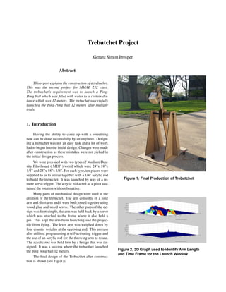
  • 1. Trebutchet Project Gerard Simon Prosper Abstract This report explains the construction of a trebuchet. This was the second project for MMAE 232 class. The trebutchet’s requirement was to launch a Ping- Pong ball which was filled with water to a certain dis- tance which was 12 meters. The trebuchet successfully launched the Ping-Pong ball 12 meters after multiple trials. 1. Introduction Having the ability to come up with a something new can be done successfully by an engineer. Design- ing a trebuchet was not an easy task and a lot of work had to be put into the initial design. Changes were made after construction as these mistakes were not picked in the initial design process. We were provided with two types of Medium Den- sity Fibreboard ( MDF ) wood which were 24”x 18”x 1/4” and 24”x 18”x 1/8”. For each type, ten pieces were supplied to us to utilize together with a 1/4” acrylic rod to build the trebuchet. It was launched by way of a re- mote servo trigger. The acrylic rod acted as a pivot sus- tained the rotation without breaking. Many parts of mechanical design were used in the creation of the trebuchet. The arm consisted of a long arm and short arm and it were both joined together using wood glue and wood screw. The other parts of the de- sign was kept simple, the arm was held back by a servo which was attached to the frame where it also held a pin. This kept the arm from launching and the projec- tile from flying. The lever arm was weighed down by four counter weights at the opposing end. This process also utilized programming a self-activating trigger and the use of an acrylic rod for the throwing arm to rotate. The acyclic rod was held firm by a bridge that was de- signed. It was a success where the trebucthet launched the ping pong ball 12 meters. The final design of the Trebucthet after construc- tion is shown (see Fig.(1)). Figure 1. Final Production of Trebutchet Figure 2. 3D Graph used to identify Arm Length and Time Frame for the Launch Window
  • 2. Table 1. Values for Trigger Calculation Variable Value Length of short arm (l) 330 mm Length of long arm (L) 560 mm Total mass of counter weight (m) 2 kg Gravitational force (g) 9.81 m/s2 Launch Angle in degrees (θ) 87.97 2. Concept Generation and Evaluation There are various methods to build a successful tre- butchet. One of the key points here is to ensure that the structure is strong and rigid to prevent failure. We did this by interlocking our edges. A Matlab code was pro- vided by our lecturer that find the best possible launch window by varying two parameters which the distance from pivot point to projectile and length from pivot to hinge. Also varied were the length of rope attaching ping pong ball to the arm, pivot height and the effi- ciency in the Matlab coding This was done to save time in building a failed trebuchet. The code then takes these varied parameters and using the equations that describe the kinematics of a trebuchet launching a ball, creates a three-dimensional mesh-grid plot of launch distance vs. arm length and time (see Fig.(s)) which is used to locate the optimal lengths of the pivot arm. It will also provide a graphed estimation of how far our tre- buchet will launch as well as how much force will be applied to the acrylic rod, which the arm rotates around. A nested ’for’ loop and a ’surf’ command were done in the code to achieve the required three-dimensional mesh-grid plot graph (see Fig.(2)). 3. Analysis Before any construction began, analysis has to be done to ensure that the item will be able to function without any flaws. This is applicable for the trebuchet also. Prior to any prototype design done in Autodesk Inventor, we took a deeper look at the various forces that was acting at different parts of the trebuchet. The force from the servo to release the trigger was initially calculated. This force allows the arm to begin its swing and will cause deflection in the acrylic rod. From the force calculated above, the deflection in the acrylic rod can be calculated to ensure that the acrylic rod will not break upon release from the trigger. Figure 3. Free Body Diagram of Forces Acting on the System Table 2. Values for Servo Torque Calculation Variable Value Torque Servo Can Produce 350 N mm Distance from Pin to Origin ( x ) 40 mm Coefficient of Friction(µ) 0.8 Ftrigger 11.56 N 3.1. Force Acting on the Trigger When calculating the force acting on the trigger from the trebuchet, we first draw a free body diagram of all the forces acting on the system (see Fig.(3)) to determine the force acting on the trigger. By summing the moments about point O, we were able to to come up with the following equation : Ftrigger = l(mg) Lsin(θ) (1) Ftrigger is the force acting on the trigger, l is the Figure 4. Free Body Diagram of Forces Acting on the Trigger
  • 3. length of the short arm, m is the total mass of the counter weight, g is the gravitational force, L is the length of the long arm and (θ) is the launch angle in degrees. Equation (1), the information from the free body diagram of the trigger(see Fig.(4)) and the data (Table (1)) are used to calculate the force acting on the trigger. We found the force acting on the trigger to be 11.56 Newtons. To find the whether the torque produced by the servo is enough to use for the trigger, we sum the moments in the free body diagram of the trigger (see Fig.(4)) about where the servo is attached. Using the equation : Mo = (xFtrigger)+τservo −x(τservoFtrigger) (2) Where Mo is the moment about the origin of rota- tion, x is the distance from the pin to the origin, Ftrigger is the force acting on the trigger, and τservo is the torque required by the servo for the trigger. Knowing ΣMo = 0, we were able to solve for τservo and it brought us to (3) : τservo = x(−µFtrigger +Ftrigger) (3) Based on the values for trigger calculation (see Ta- ble (2)) and as well as the knowledge from (3) we ob- tained the torque required for the servo for the trigger of 92.48 N mm, which is less than 350 N mm, the torque the can produce. Therefore, the trigger design was used. 3.2. Shear Stress within Acrylic Rod We then moved on to calculate the force acting on the acrylic rod due to counter weights. This will create a bending moment in the rod (see Fig (5)), which could cause the rod to fail. To be certain the trebuchet will be able to launch as calculated we calculated the shear stress using the equation below : τmax = TR Ip (4) where τmax is the maximum shear stress produced, T is the bending moment or torque produced inside the rod, R is the radius of the rod which is 3.175 mm and Ip is the moment of inertia. To find T, we use the following equation : T = Ryz−F(z− lA 2 ) (5) where Ry is the peak force obtained from Matlab graph (see Fig (6)), lA is the length acrylic rod, z is the total length of the arm from end to end and F is the Table 3. Values for Torque inside rod Calcula- tion Variable Value Peak Reaction Force (Ry) 22 N Length of acrylic rod (la) 20 mm Total length of arm (z) 0.8 Force of hanging mass (F) 19.62 N Figure 5. Free Body Diagram of Forces Creat- ing Bending Moment on Acrylic Rod force or total weight of the counter weights(see Fig (7)). Based on the data provided (see Table (3)), the torque obtained is 2,314.40 N mm. To obtain the moment of inertia, the following equation was used : Ip = πd4 32 (6) where d is the diameter of the acrylic rod which is 6.35 mm. We obtained the moment of inertia to be 159.623 kg mm4. With the torque and moment of inertia calculated with the radius of the acrylic rod given, using (4), the shear stress calculated is 46.048N/mm2 and is smaller than the ultimate tensile force of acrylic rod which is 70 N/mm2. 3.3. Pin Deflection Now that the shear stress is calculated, we are now able to calculate the maximum pin deflection using the below equation δ = FRylA AE (7) where FRy is the peak force acting on the acrylic rod from Matlab graph, lA is the length of the acrylic rod, A is the area of the acrylic rod, E is elastic modulus
  • 4. Figure 6. Graph Showing Reaction Force on Pivot Table 4. Values for Pin Deflection Calculation Variable Value Peak Reaction Force (FRy) 22 N Length of acrylic rod (la) 20 mm Cross Sectional Area of acrylic rod (A) 4.9879 mm2 Elastic Modulus of acrylic rod (E) 3,200 N/mm2 of the acrylic rod. Based on the data (see Table (4)), we obtained a deflection of 0.02757 mm which is very small and it is negligible. 4. Experimental Results We successfully managed to launch 12 meters which was satisfactory according to our standards. We officially had five chances to launch and used the fur- thest distance we obtained. Before this, we conducted a trial run without the servo and the acrylic rod broke. Upon inspection, we noted that prior to launch, the arm was not aligned straight with the bridge that was hold- ing the acrylic rod. Furthermore, the bridge itself was not a rigid structure hence, it caused the acrylic rod to be unstable. Besides this, the counter weight box added an extra one kg to the existing two kg of counter weight. Due to the sudden increase in force of the counter weight, the bridge structure being unstable and the arm not being aligned, all this caused the acrylic rod to break into two pieces. We came with a new bridge design with extra support for the acrylic rod and prior to launch again, ensured that the arm was aligned in the right way. We removed the counter weight box and just tied all four of the acrylic rod and connected it to the arm using a string. This proved effective as we manged to launch 12 meters. Figure 7. Free Body Diagram of Force acting on Swing Arm 5. Discussion We managed to attain 12 meters due to a few rea- sons and one of it was the holder of the ping pong ball. This holder kept the ping pong ball in place and released it when required during the launching of the trebuchet. In the beginning after all the pieces were cut, we started to assemble them and realized that some parts had some difficulty to fit into each other. This was due negligence on our part as we should have cut the openings or holes slightly bigger for the parts to be assembled. Neverthe- less, to ensure that all the parts fitted together, we used a hammer to knock the parts to fit. The base support was divided into four where each side had two supports to prevent the entire structure from failing. Further- more, with the new design of the bridge, the arm with the acrylic rod was rigid and prevented not too much movement from side to side at the center of the bridge. Overall this was a fun and exciting learning experience that we could use in the future. 6. Conclusions We had a goal which was to build a functional tre- buchet that was able to launch a water filled ping pong ball a certain distance. Through hard work and perse- verance, this goal was achieved and we launched the water filled ping pong ball 12 meters. The design pro- cess was assisted by MatLab in giving us the proper dimensions of our pieces for maximum results. The project allowed us to further advance our Autodesk In- ventor skills. The trebuchet remained functional all day, and still is a sound machine. The skills and techniques of design, analysis and clear thinking are a required skill for engineering students. This project assisted in this greatly.