Tài liệu (Phần 2) | Hệ thống HVAC
•
17 gostaram•3,899 visualizações

Tài liệu (Phần 3) | Hệ thống HVAC

Recomendados
Recomendados
Mais conteúdo relacionado
Mais procurados
Mais procurados (20)
Semelhante a Tài liệu (Phần 2) | Hệ thống HVAC
Semelhante a Tài liệu (Phần 2) | Hệ thống HVAC (20)
Mais de Công ty cổ phần GMPc Việt Nam | Tư vấn GMP, HS GMP, CGMP ASEAN, EU GMP, WHO GMP
Mais de Công ty cổ phần GMPc Việt Nam | Tư vấn GMP, HS GMP, CGMP ASEAN, EU GMP, WHO GMP (20)
Último
Último (20)
Tài liệu (Phần 2) | Hệ thống HVAC
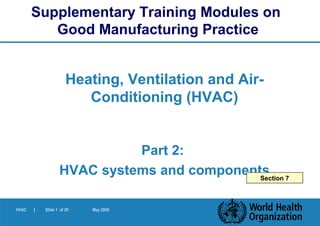
- 1. HVAC | Slide 1 of 29 May 2006 Heating, Ventilation and Air- Conditioning (HVAC) Part 2: HVAC systems and components Supplementary Training Modules on Good Manufacturing Practice Section 7
- 2. HVAC | Slide 2 of 29 May 2006 Objectives In the following slides, we will study the components of air- handling systems in order to: 1. Become familiar with the components 2. Know their functions 3. Become aware of possible problems HVAC
- 3. HVAC | Slide 3 of 29 May 2006 HVAC General Design of HVAC is dependent on required degree of air cleanliness Suitable components should be selected including: – fans, – driers, – filters, – ducts, grilles, etc. 7.
- 4. HVAC | Slide 4 of 29 May 2006 + Production Room Exhaust air treatment Central air handling unit Terminal air treatment at production room level Fresh air treatment (make-up air) HVAC Main subsystems
- 5. HVAC | Slide 5 of 29 May 2006 HVAC Components Components in HVAC may include, depending on need: Filters Fans – no fan failure; including supply air fans, return air fans, exhaust air fan, dust extract system fans Driers – Drying of air with chemical driers, e.g. rotating desiccant wheel Frost coils for preheating air 7.1.1 – 7.1.7
- 6. HVAC | Slide 6 of 29 May 2006 HVAC Components Components in HVAC may include, depending on need: Snow eliminators Dust eliminators Moisture eliminators Precooling coils Alarm systems, grilles/diffusers, etc. 7.1.1 – 7.1.7
- 7. HVAC | Slide 7 of 29 May 2006 FilterSilencer Terminal filter Weather louvre Control damper FanFlow rate controller Humidifier Heating coil Cooling coil with droplet separator Production Room Overview components + Prefilter Exhaust Air Grille Heater Secondary Filter Recirculated air HVAC
- 8. HVAC | Slide 8 of 29 May 2006 Weather louvre Silencer Flow rate controller Control damper To prevent insects, leaves, dirt and rain from entering To reduce noise caused by air circulation Automated adjustment of volume of air (night and day, pressure control) Fixed adjustment of volume of air Components (1) HVAC
- 9. HVAC | Slide 9 of 29 May 2006 Heating unit Cooling unit/ dehumidifier Humidifier Filters Ducts To heat the air to the proper temperature To cool the air to the required temperature or to remove moisture from the air To bring the air to the proper humidity, if too low To eliminate particles of predetermined dimensions and/or microorganisms To transport the air Components (2) HVAC
- 10. HVAC | Slide 10 of 29 May 2006 Control damper for airflow De-humidification Filter Pressure Gauges AHU with fan Variable Speed Controller Humid room air Air heater Regeneration air Humid room air Adsorber wheel Dry air Air-handling unit HVAC
- 11. HVAC | Slide 11 of 29 May 2006 Humidifier Silencer Heating and cooling units HVAC
- 12. HVAC | Slide 12 of 29 May 2006 Filter classes Dust filters Standard Aerosol FineCoarse ULPAHEPA 10 µ m > Dp > 1 µ mDp > 10 µ m Dp < 1 µ m F5 - F9G1 - G4 U 14- 17H 11 - 13 EN 1822 StandardEN 779 Standard HVAC
- 13. HVAC | Slide 13 of 29 May 2006 Primary panel filter Secondary filter HEPA or tertiary filter HVAC
- 14. HVAC | Slide 14 of 29 May 2006 Average Efficiency Integral Value Peak Arrestance Local Value Retention in % Penetration Efficiency Penetration F9 85 0.15 H11 95 0.05 H12 99.5 5x10 -3 97.5 25x10 -3 H13 99.95 5x10 -4 99.75 25x10 -4 U14 99.995 5x10 -5 99.975 25x10 -5 Classification of filters according to their efficiency HVAC
- 15. HVAC | Slide 15 of 29 May 2006 Positioning of filters (1) Filter in terminal positionAHU mounted final filter Production Room + Production Room HEPA Filter HEPA Filter HVAC
- 16. HVAC | Slide 16 of 29 May 2006 Prefilter AHU Main filter 1 2 3 Low level exhausts Ceiling exhausts Positioning of filters (2) HVAC
- 17. HVAC | Slide 17 of 29 May 2006 AHU Prefilter Final filter 21 Positioning of filters (3) HVAC
- 18. HVAC | Slide 18 of 29 May 2006 Swirl Type air diffusors with terminal filters1 Filter 2 Tightening frame 3 Register outlet 4 Screw fixation for register 1 2 3 4 HVAC
- 19. HVAC | Slide 19 of 29 May 2006 Low induction swirl diffusor (preferred) High induction office type diffusor (avoid) HVAC
- 20. HVAC | Slide 20 of 29 May 2006 Regulation of room pressure – pressure differentials concept Room pressure gauges Room pressure indication panel HVAC
- 21. HVAC | Slide 21 of 29 May 2006 Flow rate controller Control damper Humidifier Cooling battery Filters Ducts Blocked Poorly adjusted, bad pressure differential system Bad water/steam quality/ poor drainage No elimination of condensed water/ poor drainage Incorrect retention rate/damaged/badly installed Inappropriate material/internal insulator leaking Problems with components HVAC
- 22. HVAC | Slide 22 of 29 May 2006 HVAC In the next slides Consider different air types, e.g.: Supply air Return air (recirculated air) Fresh air (make-up air) Exhaust air And: Concepts of air delivery to production areas: Recirculation systems Full fresh-air systems
- 23. HVAC | Slide 23 of 29 May 2006 + Production Room Exhaust air Return air (recirculated) Fresh air (make-up air) Supply air Air types HVAC
- 24. HVAC | Slide 24 of 29 May 2006 HVAC Recirculation systems There should be no risk of contamination and cross- contamination when air is recirculated Normally, HEPA filters (EN1822 H13) needed in supply air stream – Not required in single product facility with no risk of cross-contamination – Not required where no dust generation (e.g. secondary packaging) HEPA filters placed in AHU or terminally Dust from highly toxic processes should not be recirculated 7.2.1 – 7.2.6
- 25. HVAC | Slide 25 of 29 May 2006 Ventilation with recirculated air + make-up air Central Air-Handling Unit Return air Exhaust Unit HVAC
- 26. HVAC | Slide 26 of 29 May 2006 HVAC
- 27. HVAC | Slide 27 of 29 May 2006 HVAC Full fresh-air systems 100% fresh air - normally where toxic products are processed, and recirculation not recommended No contamination from fresh air – sufficient filtration needed Degree of filtration on exhaust dependent on exhaust air contaminants and environment regulations Energy-recovery wheels – Should not be source of contamination – Relative pressure between supply and exhaust air 7.3.1 – 7.3.3
- 28. HVAC | Slide 28 of 29 May 2006 Ventilation with 100% fresh air (no air recirculation) W Washer (optional) Central Air-Handling Unit Production Rooms Exhaust Unit HVAC
- 29. HVAC | Slide 29 of 29 May 2006 HVAC
Notas do Editor
- &lt;number&gt; अगस्त 6, 2014
- &lt;number&gt; अगस्त 6, 2014 Objectives: For you, as inspectors, to be able to judge whether the air handling systems which you encounter during your factory inspections are adequate or not, it is necessary to know how such systems work, and to be aware of what problems may arise in terms of the components of the system. Therefore, the objectives of this part of module 3 are to study the components of air handling systems in order to: Become familiar with the components Know their functions Become aware of possible problems
- &lt;number&gt; अगस्त 6, 2014 7. HVAC systems and components Note: The required degree of air cleanliness in most OSD manufacturing facilities can normally be achieved without the use of high-effi ciency particulate air (HEPA) fi lters, provided the air is not recirculated. Many open product zones of OSD form facilities are capable of meeting ISO 14644-1 Class 8, “at-rest” condition, measured against particle sizes of 0.5 μm and 5 μm, but cleanliness may not be classifi ed as such by manufacturers.
- &lt;number&gt; अगस्त 6, 2014 To understand the air handling systems, it is necessary to know what their components are. A conventional Air Handling System has 4 sub-systems: 1. Air handling of the incoming (fresh) air: elimination of coarse contaminants and protection from frost if necessary. In the case of air re-circulation, the fresh air is also called make-up air. 2. Central air handling unit (AHU), where the air will be conditioned (heated, cooled, humidified or de-humidified and filtered), and where fresh air and re-circulated air, if any, (indicated here by the dotted line) will be mixed. 3. Air handling in the rooms under consideration (pressure differential system, additional filtration, air distribution). 4. Air exhaust system (filtration).
- &lt;number&gt; अगस्त 6, 2014 7.1 General 7.1.1 There should be no failure of a supply air fan, return air fan, exhaust air fan or dust extract system fan. Failure can cause a system imbalance, resulting in a pressure cascade malfunction with a resultant airfl ow reversal. 7.1.2 A schematic diagram of the airfl ow for a typical system serving a low humidity suite is represented in Fig. 23. 7.1.3 Air should be dried with a chemical drier (e.g. a rotating desiccant wheel which is continuously regenerated by means of passing hot air through one segment of the wheel). 7.1.4 The fi gure illustrates the chemical drier handling part of the fresh air/return air mixture on a by-pass fl ow. The location of the chemical drier should be considered in the design phase. Examples of appropriate locations include: — full fl ow of fresh/return air; — partial handling of fresh/return air (by-pass airfl ow); — return air only; — fresh air only; or — pre-cooled air with any of the above alternatives. 7.1.5 Possible additional components that may be required should be considered depending on the climatic conditions and locations. These may include items such as: — frost coils on fresh air inlets in very cold climates to preheat the air; — snow eliminators to prevent snow entering air inlets and blocking airfl ow; — dust eliminators on air inlets in arid and dusty locations; — moisture eliminators in humid areas with high rainfall; and — fresh air pre-cooling coils for very hot or humid climates. 7.1.6 Appropriate alarm systems should be in place to alert personnel if a critical fan fails. 7.1.7 Low-level return or exhaust air grilles are usually preferred. However, where this is not possible, a higher air change rate may be needed to achieve a specifi ed clean area classifi cation, e.g. where ceiling return air grilles are used.
- &lt;number&gt; अगस्त 6, 2014
- &lt;number&gt; अगस्त 6, 2014 Another way to look at an air handling system is to consider the different components and to know their function. Some of the components, particularly the filters, are essential to ensure the quality of the air. We will later consider individual components in detail. Of course, a well-designed air handling system must not only be properly designed, but also properly installed, qualified and maintained (sealed ducts, tight filters). (The trainer should make the audience aware that this slide is just an example, and that all components may not necessarily be present in each system.)
- &lt;number&gt; अगस्त 6, 2014 A typical HVAC unit consists of a small number of elements only. It is important that these elements are compatible, properly installed, and fulfilling their goal. Whereas a weather louvre and silencer are less critical elements, the components associated with the flow rate control are essential, as they allow adjustment of the air volumes supplied to the rooms, which in turn forms the base for a pressure differential concept: to have an automated or a fixed system is largely a financial matter, but a fixed system is more difficult to set up. Silencer – check internal lining material of silencer as this can cause contamination.
- &lt;number&gt; अगस्त 6, 2014 Heating and cooling units (batteries), as well as humidifiers are used to adjust the climate in the room (temperature and humidity). Special de-humidifiers, on a dessiccant base, will be addressed later. Filters are one of the main components, as they determine the size of airborne particles that pass through them, and thus the hygiene class. It is wise to protect the finer filters by pre-filters, thus extending their life cycles, and making them less prone to clogging. Ducts transport the air from the air handling units to and from the rooms. Inspectors must verify that ducts do not have internal insulation as this is a great source of contamination.
- &lt;number&gt; अगस्त 6, 2014 Dampers to control pressure differentials are important. They can be automated or fixed. As filters get dirty the system pressure losses increase, and if airflow is not regulated, the flow decreases and pressure differentials change. This could cause flow reversal and cross-contamination. Variable speed drives for fan motors are also commonly used to control airflow. In some cases, it is necessary to have very dry air for galenical reasons in certain rooms (production of effervescent tablets and humidity sensitive products in general). To generate dry air, the air supplied to the production is passed over an adsorbant (silicagel, lithium chloride, etc.) where the humidity is removed from the air. The adsorbant is then re-generated, on a continuous or on a batch-wise base.
- &lt;number&gt; अगस्त 6, 2014 This slide shows additional elements of the air handling units. For humidification purposes, especially in clean areas, high purity water should be used, to avoid contamination. The silencer is not important from a GMP point of view, but from an environmental one, as ventilation units can be very noisy. Be sure that the silencers are manufactured of suitable materials as the linings of standard silencers can contaminate air with particulates. Depending on the local legislation, the installation of silencers can be mandatory. The cooling unit is important during the hot season. Be aware that stagnating water (condensed water) can bring bacterial growth, which can contaminate the filters, pass through them (depending on their retention properties) and end up contaminating production areas. It is essential that there is no stagnating water. Cooling coils can be sanitized as well. Do remember that, if filters are not properly maintained, micro-organisms may grow through the filters and be carried towards the production rooms.
- &lt;number&gt; अगस्त 6, 2014 The filtration efficacy depends on several mechanisms, and results in a rough filter classification. The diagram shows the commonly used classification, with current abbreviations G = Gross, F= Fine, H= High, U= Ultra. Filters are certified by the suppliers (challenge/efficiency test), but are often not properly installed or can be damaged. Leak tests (integrity tests), showing leakage of air through the filter itself or through its frame, therefore, have to be performed. Integrity tests are usually only carried out on the Aerosol filters (HEPA & ULPA). Integrity or penetration testing is performed to detect leaks from the filter media, filter frame and seal. The challenge is a poly-dispersed aerosol usually composed of particles ranging in size from one to three microns. The test is done in place and the filter face is scanned with a photometer probe; the measured downstream leakage is taken as a percentage of the upstream challenge. Integrity tests should be carried out with filters installed in the system and should be carried out by an independent body (not the filter supplier). The efficiency test, on the other hand, is used to determine the filter&apos;s rating. This test uses a mono-dispersed aerosol of 0.3 micron size particles, relates to filter media, and usually requires specialized equipment. Downstream readings represent an average over the entire filter surface. Therefore, leaks in a filter may not be detected by an efficiency test.
- &lt;number&gt; अगस्त 6, 2014 This slide shows Primary Panel filters, which are used mainly for lower filtration efficiency or as pre-filters Secondary filters, consisting of mini-pleated media or filter bags, and is used for higher filtration efficiency. HEPA or tertiary filters, usually being the final filter in the system, providing the highest filtration efficiency. Though there is a strong relationship between filter efficiency and cleanroom class, a filter of a high efficiency does not guarantee a high cleanroom class, as many other elements play a role, such as Air flow (how the air is extracted, how well the room is “flushed”) Air speed and number of air changes Positions of air terminals Layout and presence of objects Personnel and clothing Equipment (not all machines are designed to operate in a clean environment!) Proper installation and proper maintenance
- &lt;number&gt; अगस्त 6, 2014 This table gives an idea of the efficiency of the filters, calculated across the entire surface (integral value) or in particular spots (local value). Referring to filter ratings by percent efficiency is misleading, as there are so many different types of tests that give different efficiencies for the same filter. This can be very confusing and it is better to refer to the Committee of European Normalisation (EN) test rating i.e. G4, F8, H12, etc.
- &lt;number&gt; अगस्त 6, 2014 In some of the previous slides, we have seen filters both in the central air handling units ( AHU ) and terminally mounted at the production rooms. The filtered air entering a production room can be coming from: an air-handling unit, equipped with pre-filtration and the main (HEPA) filter, but at some distance from that room (left drawing); an air-handling unit, equipped with pre-filtration in the AHU, and an additional filter (HEPA) situated immediately on the air outlet (right drawing). In many cases, there are only filters in the AHU. However, for injectables and sterile forms, it is recommended that they be placed in terminal position, though there is a growing tendency to have terminal filters in all rooms where open products are handled. It is recommended that classes A & B (ISO 4, 5 & 6) have terminal HEPA filters. (Refer to: WHO Export Committee on Specifications for Pharmaceutical Preparations. Thirty-second Report. Geneva, World Health Organization, 1992:59-60 (Technical Report Series, No. 823). Annex 1, 17.3.) If we look at the advantages and disadvantages of terminal or non-terminal filters, we can say that generally speaking, the terminal positioning is more expensive; provides a better protection (any problem arising from the ducts is eliminated); is the preferred method in cleanroom classes with high requirements.
- &lt;number&gt; अगस्त 6, 2014 Filters can be in different positions, when one considers the central AHU and the rooms. This slide shows an HVAC installation feeding 3 rooms, each one with terminal filters, all filters protected by a remote pre-filter. Room 1 has a turbulent air flow, with low level exhaust. Room 2 has a uni-directional (laminar) air flow over the largest part of the surface, hence the large number of filters. Room 3 has a turbulent air flow, with ceiling exhaust.
- &lt;number&gt; अगस्त 6, 2014 This slide shows an HVAC installation feeding two rooms, each one without terminal filters, but with remote final filters protected by a pre-filter. Room 1 has a turbulentair flow, with low level exhaust. Room 2 has a turbulent air flow, with ceiling exhaust. If there is no filter in terminal position, it should be ascertained that there are no elements between the main filter and the air outlets which could add contamination. No elements such as fans, heating/cooling batteries, should be situated downstream of the final filter.
- &lt;number&gt; अगस्त 6, 2014 The air flows into the rooms via so-called registers (diffusors), which are built and installed in such a way that the air is distributed evenly. Machinery or furniture can block the passage of air from the register to the exhaust point, creating unflushed zones, where counts of particles and micro-organisms could be higher. It is therefore important to consider the content of a clean room, when planning the HVAC system. In many cases, the terminal filter panel and diffusors are incorporated into one unit. It is also important that the air diffuser supplies air evenly and does not induce the circulation of dust in the room – as illustrated by the next slide.
- &lt;number&gt; अगस्त 6, 2014 The diffuser on the left is a normal office type diffuser which induces a lot of air to rise vertically from the floor towards the ceiling. The rising induced air has the potential for carrying a lot of dust upwards which is then spread throughout the room with the air supply. This type of diffuser readily spreads contaminants in the room and should be avoided. The preferred type of diffuser for cleanroom applications is the swirl diffuser, or perforated plate diffuser. These types do not promote the spread of dust within the room.
- &lt;number&gt; अगस्त 6, 2014 One of the main points in the design of production rooms is the pressure differentials concept. Pressure differentials must be defined, monitored and alarmed in critical cases. The overpressure of each room is measured against a reference point in the factory (point zero). As discussed earlier, the pressure regulation can be fixed or automated. Pressure control can be by means of automatic air flow control dampers (as shown in slide 15) or by means of fan speed control. Whatever the means used it is important to ask the manufacturer how they ensure that the pressure cascade is maintained as the filters get dirty. In the following slides, we are going to see that an overpressure concept can be very different for sterile products and for solid products.
- &lt;number&gt; अगस्त 6, 2014 Problems may arise with components, with the following consequences: Flow rate controllerBlockedNo control of pressure differentials Control damperPoorly adjustedBad pressure differential systems HumidifierBad water/Risks of microbial contamination steam quality Cooling UnitNo eliminationRisks of microbial contamination of condensed water FiltersIncorrect retention Risks of contamination rate(particles, micro-organisms) DamagedFilter integrity fails Badly installedRisks of contamination (particles, micro-organisms) DuctsInappropriate materialDanger of corrosion Leaking duct workIntake of unfiltered air Internal insulationInability to properly clean
- &lt;number&gt; अगस्त 6, 2014 In this session we want you to achieve the following: 1. To understand the key issues in relation to quality assurance and quality control. 2. To understand the special needs in terms of organization, procedures, processes and resources, including staffing. 3. In your group session, to look at the special situations and problems that you face in these areas in your country, and to develop practical solutions. This area of work is potentially difficult because of the need to understand clearly the difference between quality management, quality assurance (QA) and quality control (QC). We will be looking at the issues that can arise in implementation, and at your own experiences. We will consider questions such as what to do about the owner of a factory who insists on appointing his/her son or daughter, who is not qualified, into a position of responsibility, and what to do about a factory that insists that it can manufacture penicillin products without cross-contamination risk, in the same equipment and premises used for manufacture of other types of product.
- &lt;number&gt; अगस्त 6, 2014 There are different air types to be considered within the air handling system: Fresh air (if the plant is of the re-circulation type, it is necessary to replace some of the re-circulating air with fresh air, which is then called make-up air). A proportion of about 15% fresh air is normal, but this proportion can vary, depending on factors such as number of people, National Regulatory Authority requirements, the presence of certain substances in the air, leakage due to pressure control, etc. Supply air to the rooms Exhaust air from the rooms Return air (about 85% is being re-circulated)
- &lt;number&gt; अगस्त 6, 2014 7.2 Recirculation system 7.2.1 There should be no risk of contamination or cross-contamination (including by fumes and volatiles) due to recirculation of air. 7.2.2 Depending on the airborne contaminants in the return-air system it may be acceptable to use recirculated air, provided that HEPA fi lters are installed in the supply air stream to remove contaminants and thus prevent cross-contamination. The HEPA fi lters for this application should have an EN1822 classifi cation of H13. 7.2.3 HEPA fi lters may not be required where the air-handling system is serving a single product facility and there is evidence that cross-contamination would not be possible. 7.2.4 Recirculation of air from areas where pharmaceutical dust is not generated such as secondary packing, may not require HEPA fi lters in the system. 7.2.5 HEPA fi lters may be located in the air-handling unit or placed terminally. 7.2.6 Air containing dust from highly toxic processes should never be recirculated to the HVAC system.
- &lt;number&gt; अगस्त 6, 2014 This slide illustrates a typical re-circulated air setup, where a central unit distributes a mixture of fresh and re-circulated air to different production rooms. A part of the exhaust air is collected in a central duct, treated (filtered) and exhausted. The rest is re-circulated (dotted line). With control dampers, the proportions of fresh and re-circulated air can be adjusted.
- &lt;number&gt; अगस्त 6, 2014
- &lt;number&gt; अगस्त 6, 2014 7.3 Full fresh air systems Fig. 26 indicates a system operating on 100% fresh air and would normally be used in a facility dealing with toxic products, where recirculation of air with contaminants should be avoided. 7.3.1 The required degree of fi ltration of the exhaust air depends on the exhaust air contaminants and local environmental regulations. 7.3.2 Energy-recovery wheels should normally not be used in multiproduct facilities. When such wheels are used they should not become a source of possible contamination (see Fig. 27). Note: Alternatives to the energy-recovery wheels, such as crossover plate heat exchangers and watercoil heat exchangers, may be used in multiproduct facilities. 7.3.3 The potential for air leakage between the supply air and exhaust air as it passes through the wheel should be prevented. The relative pressures between supply and exhaust air systems should be such that the exhaust air system operates at a lower pressure than the supply system.
- &lt;number&gt; अगस्त 6, 2014 This slide illustrates a typical 100% fresh air setup, where a central unit distributes the fresh, treated air to different production rooms. The exhaust air is collected in a central duct, treated (filtered or washed) and eliminated. The degree of exhaust air filtration will depend on contaminants in the exhaust air and also on environmental regulations.
- &lt;number&gt; अगस्त 6, 2014