
Recomendados
Mais conteúdo relacionado
Mais procurados
Destaque
Semelhante a 95ZJ_8T.PDF
Semelhante a 95ZJ_8T.PDF (20)
Mais de Åge Færestrand
Mais de Åge Færestrand (10)
Último
Último (20)
95ZJ_8T.PDF
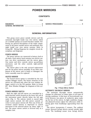
- 1. ZJ POWER MIRRORS 8T - 1 POWER MIRRORS CONTENTS page page DIAGNOSIS . . . . . . . . . . . . . . . . . . . . . . . . . . . . . 2 SERVICE PROCEDURES ................... 4 GENERAL INFORMATION . . . . . . . . . . . . . . . . . . 1 GENERAL INFORMATION This group covers power outside mirrors and the automatic day/night inside rear view mirror, which are available options on Grand Cherokee models. Fol- lowing are general descriptions of the major compo- nents in the power outside mirror and automatic day/ night inside rear view mirror systems. Refer to Group 8W - Wiring Diagrams for complete circuit de- scriptions and diagrams. POWER MIRROR The power mirrors are connected to battery feed at all times. Each mirror head contains two electric mo- tors, two drive mechanisms and the mirror glass. One motor and drive controls mirror up-and-down movement, and the other controls right-and-left movement. The mirror glass is the only serviced replacement part for the power mirror assembly. If any other com- ponent of the mirror unit is faulty or damaged, the entire assembly must be replaced. HEATED MIRROR The heated mirror option is controlled by the rear window defogger switch. The heater elements in the mirror are activated only when the rear window de- fogger switch is in the ON position. Refer to Group 8N - Rear Window Defogger for diagnosis of this sys- tem. Fig. 1 Power Mirror Switch AUTOMATIC DAY/NIGHT MIRROR POWER MIRROR SWITCH The automatic day/night mirror automatically Both the right and left mirror are controlled by a changes its reflectance to reduce glare in all types of multi-function switch located on the lower left end of driving conditions. A thin layer of electrochromic ma- the instrument panel, directly below the left spot terial between two pieces of conductive glass make cooler (Fig. 1). The selector switch is moved right up the face of the mirror. As light conditions change, (right mirror control), left (left mirror control), or two photocell sensors adjust the reflectance while re- center to turn power mirrors off. Then one of four di- ducing glare from headlamps approaching from the rectional control buttons is depressed to control rear. movement of the selected mirror up, down, right, or The mirror incorporates 2 sensors. The ambient left. The power mirror switch is serviced only as a sensor (forward facing) detects normal outside light complete unit. levels. The headlamp sensor (rear facing) detects
- 2. 8T - 2 POWER MIRRORS ZJ light levels received at the rear window side of the only operate when the ignition switch is in the ON mirror. When the difference between the two levels position. The mirror also senses the back-up lamp becomes too great (light level received at rear of mir- circuit and turns off whenever the transmission ror is much higher than front of mirror), the mirror (manual or automatic) is in reverse. begins to darken. The automatic day/night mirror can not be re- The mirror switch controls whether the automatic paired. If faulty, the entire assembly must be re- dimming feature is on or off. When on is selected, the placed. switch is lighted by an integral LED. The mirror will DIAGNOSIS POWER MIRRORS (1) Remove the door trim panel as described in Power Mirror Remove/Install. (2) Unplug power mirror door wiring harness con- nector. (3) Connect a jumper wire to a 12-volt source. (4) Connect another jumper wire to a good body ground. (5) Refer to Power Mirror Motor Test for appropri- ate pin numbers (Fig. 2). Fig. 3 Power Mirror Switch Test Fig. 2 Power Mirror Motor Test (4) Turn ignition switch to OFF position. Check for POWER MIRROR SWITCH continuity between connector cavity with black wire (1) Remove power mirror switch from mounting po- sition. (2) Unplug wiring harness connector. (3) Using an ohmmeter, test for continuity between the terminals of the switch as shown in the Power Mirror Switch Test (Fig. 3). AUTOMATIC DAY/NIGHT MIRROR (1) Check fuse 19 in fuseblock module. If OK, go to next step. If not OK, replace fuse. (2) Turn ignition switch to the ON position. Check for battery voltage at fuse 19 in fuseblock module. If OK, go to next step. If not OK, repair circuit from fuse to ignition switch as required. (3) Unplug harness connector from mirror (Fig. 4). With ignition switch ON, check for battery voltage at connector cavity with yellow wire. If OK, go to next step. If not OK, repair circuit to fuse 19 as required. Fig. 4 Automatic Rear View Mirror
- 3. ZJ POWER MIRRORS 8T - 3 POWER MIRROR SCHEMATIC and a good ground. There should be continuity. If bient light. Light sensor must be covered com- OK, go to next step. If not OK, repair circuit to pletely so that no light reaches the sensor. Use ground as required. only one finger pressed tightly against sensor, (5) Turn ignition switch to ON position. Set park- or cover sensor completely with electrical tape. ing brake. Place transmission gear selector in Re- (7) Shine a light into the rear facing sensor. The verse position. Check for battery voltage at connector mirror should darken. If OK, go to next step. If not cavity with brown/light green wire. If OK, plug mir- OK, replace mirror ror connector back in and go to next step. If not OK, (8) With the mirror darkened, place the transmis- repair circuit to back-up lamps as required. sion gear selector in Reverse. The mirror should re- (6) Place transmission gear selector in Neutral. turn to its normal condition. If not OK, replace Place mirror switch in ON (switch lighted) position. mirror. Cover the forward facing sensor to keep out any am-
- 4. 8T - 4 POWER MIRRORS ZJ SERVICE PROCEDURES POWER MIRROR SWITCH REMOVE/INSTALL (1) Disconnect battery negative cable. (2) Remove ash receiver. (3) Remove 6 screws holding instrument panel cen- ter bezel (Fig. 5). Fig. 6 Upper Dash Pad Attaching Screws Fig. 7 Cluster to Dash Pad Screws Fig. 5 Instrument Panel Center Bezel (4) Remove center bezel. (5) Remove 2 screws holding dash pad located be- hind top of center bezel. (6) Gently pry defroster grille out of dash pad. (7) Unplug auto headlamp and/or solar sensors (if equipped) and set defroster grille aside. (8) Remove 4 screws in defroster duct opening holding dash pad (Fig. 6). (9) Remove 3 screws above instrument panel clus- ter holding dash pad (Fig. 7). (10) Open glove box and remove 2 screws holding dash pad. (11) Remove dash pad by pulling up to unsnap end Fig. 8 Steering Column Cover clips. (14) Remove 1 screw from bottom of lower instru- (12) Remove 4 screws holding the steering column ment panel trim and pull panel off. There is also a cover (Fig. 8). clip holding the panel to the instrument panel. (13) With left front door open, remove 1 screw from (15) Remove 1 screw holding top of mirror switch the side of the lower instrument panel trim (Fig. 9). bezel (Fig. 10).
- 5. ZJ POWER MIRRORS 8T - 5 Fig. 11 Power Mirror Bezel Bottom Screw Fig. 9 Lower Instrument Panel Trim Fig. 10 Power Mirror Bezel Top Screw (16) Remove 1 screw holding bottom of bezel (Fig. Fig. 12 Power Mirror Switch Remove 11). Remove the mirror switch bezel far enough to (4) Remove screw from under door armrest. unplug connector. (5) Remove screw from bottom of hand hold in door (17) Depress locking tabs and remove switch from armrest. bezel (Fig. 12). (18) Reverse removal procedures to install. CAUTION: The wiring harness to the door switches is just long enough to allow installation. If trim POWER MIRROR REMOVE/INSTALL panel is pulled off by hand the switches may be (1) Remove screw at top of door trim panel near pulled apart. Use a door clip tool to prevent damag- mirror (Fig. 13). ing the switches. (2) Remove screw from demister opening. (3) Remove screw and door handle cover.
- 6. 8T - 6 POWER MIRRORS ZJ Fig. 15 Power Mirror Remove/Install Fig. 13 Door Trim Panel Remove AUTOMATIC DAY/NIGHT MIRROR REMOVE/ (6) Remove the door trim panel with a wide, flat- INSTALL bladed tool (Fig. 14). (1) Remove wire cover by grasping lower portion of To aid in removal of the trim panel, start at wire cover and sliding into upper portion and off of the bottom of the panel. mirror base (Fig. 16). Fig. 14 Door Trim Panel Remove Fig. 16 Automatic Rear View Mirror Remove/Install (7) Unplug mirror wiring from door harness at con- (2) Unplug connector behind mirror. nector (Fig. 15). (3) Remove screw holding mirror to windshield. (8) Remove 3 nuts holding mirror to door panel (4) Push mirror up far enough to clear the support and remove mirror. and remove mirror. (9) Reverse removal procedures to install. (5) Reverse removal procedures to install.