SlideShare uma empresa Scribd logo
1 de 32
Baixar para ler offline
ZJ                                                                            REAR SUSPENSION AND AXLES                   3-1

                              REAR SUSPENSION AND AXLES

                                                        CONTENTS

                                                          page                                                            page

AXLE NOISE/VIBRATION DIAGNOSIS . . . . . . . . . 6                 REAR SUSPENSION . . . . . . . . . . . . . . . . . . . . . . 3
AXLE SPECIFICATIONS . . . . . . . . . . . . . . . . . . . 32       TORQUE SPECIFICATIONS . . . . . . . . . . . . . . . . 32
GENERAL INFORMATION . . . . . . . . . . . . . . . . . . 1          TRAC-LOK DIFFERENTIAL . . . . . . . . . . . . . . . . . 27
MODEL 35 AXLE . . . . . . . . . . . . . . . . . . . . . . . . 10


                                             GENERAL INFORMATION

REAR SUSPENSION                                                      The upper and lower suspension arms use bushings
  The Grand Cherokee rear suspension is link/coil                  to isolate road noise. The suspension arms are bolted
design comprised of (Fig. 1);                                      to the body and axle through the rubber bushings.
• Drive axle                                                       The upper suspension arm has provision for the use
• Coil springs                                                     of cam bolts at the axle to allow for pinion angle or
• Upper and lower suspension arms                                  thrust angle adjustment. The cams are available as a
                                                                   service kit and are not installed at the factory. The
• Dual-action shock absorbers
                                                                   suspension arm travel is limited through the of use
• Track bar
                                                                   jounce bumpers in compression and shock absorbers
• Stabilizer bar
                                                                   in rebound.
• Jounce bumpers
                                                                     Suspension components which use rubber bushings
                                                                   should be tightened at vehicle ride height. This will
                                                                   prevent premature failure of the bushing and main-
                                                                   tain ride comfort. Bushings must never be lubricated.
                                                                     The coil springs mount up in the fender shield that
                                                                   is part of the unitized body bracket. There is a rub-
                                                                   ber isolator between the top of the spring and
                                                                   bracket to isolate road noise. The bottom of the
                                                                   spring seats on the axle pad and is retained with a
                                                                   clip.
                                                                     The shock absorbers dampen jounce and rebound of
                                                                   the vehicle over various road conditions. The top of
                                                                   the shock absorbers are bolted to the body. The bot-
                                                                   tom of the shocks are bolted to the axle shock ab-
                                                                   sorber bracket.
                                                                     The stabilizer bar is used to control vehicle body
                                                                   roll during turns. The spring steel bar helps to equal-
                                                                   ize the vehicle body in relationship to the suspension.
                                                                   The bar extends across the underside of the chassis
                                                                   and connects to the frame rails. Links are connected
                                                                   from the bar to the axle brackets. Stabilizer bar are
                                                                   isolated by rubber bushings.
                                                                     The track bar is used to control rear axle lateral
                                                                   movement. The track bar is attached to a frame rail
                                                                   bracket and an axle bracket. It is isolated with bush-
                                                                   ings at both ends.

                                                                   REAR AXLE
                                                                     The integral housing, hypoid design has the pinion
                 Fig. 1 Rear Suspension                            set below the ring gear.
3-2      REAR SUSPENSION AND AXLES                                                                            ZJ

   The axles are equipped with A.B.S. brake systems.         During straight ahead driving, the differential pin-
The A.B.S. tone rings are pressed onto the axle shaft      ion gears do not rotate on the pinion mate shaft. This
near the hub flange. For additional information on         occurs because input torque applied to the gears is
the A.B.S. system refer to Group 5, Brakes.                divided and distributed equally between the two side
   The Model 35 axle has the assembly part number          gears. As a result, the pinion gears revolve with the
and gear ratio listed on a tag. The tag is attached to     pinion mate shaft but do not rotate around it (Fig. 3).
                                                             When turning corners, the outside wheel must
the housing cover (Fig. 2). Build date identification
codes are stamped on the axle shaft tube cover side.
   The Model 35 axle is available with Trac-Lok™
(limited slip) differential as an option.


                                                           Fig. 3 Differential Operation—Straight-Ahead Driving
                                                           travel a greater distance than the inside wheel in or-
                                                           der to complete a turn. This difference must be com-
                                                           pensated for in order to prevent the wheels from
                                                           scuffing and skidding through the turn. To accom-
                                                           plish this, the differential allows the axle shafts to
                                                           turn at unequal speeds (Fig. 4). In this instance, the
                                                           input torque applied to the pinion gears is not di-
                                                           vided equally. The pinion gears now rotate around
                                                           the pinion mate shaft in opposite directions. This al-
          Fig. 2 Model 35 Differential Cover
                                                           lows the side gear and axle shaft attached to the out-
STANDARD DIFFERENTIAL OPERATION                            side wheel to rotate at a faster speed.
  The differential gear system divides the torque be-
tween the axle shafts. It allows the axle shafts to ro-
tate at different speeds when turning corners.
  Each differential side gear is splined to an axle
shaft. The pinion gears are mounted on a pinion
mate shaft and are free to rotate on the shaft. The
pinion gear is fitted in a bore in the differential case
and is positioned at a right angle to the axle shafts.
  In operation, power flow occurs as follows:
• Pinion gear rotates the ring gear
• Ring gear (bolted to the differential case) rotates
the case
• Differential pinion gears (mounted on the pinion
mate shaft in the case) rotate the side gears
• Side gears (splined to the axle shafts) rotate the
shafts                                                            Fig. 4 Differential Operation—On Turns
ZJ                                                                                                                                       REAR SUSPENSION AND AXLES                                                              3-3

                                                                                        REAR SUSPENSION


                                                                                                                        INDEX
                                                                                                                page                                                                                                                page

Coil Spring . . . . . . . . .   .   .   .   .   .   .   .   .   .   .   .   .   .   .   .   .   .   .   .   .   .   .   4   Spring and Shock Diagnosis              .   .   .   .   .   .   .   .   .   .   .   .   .   .   .   .   .   .   4
Lower Suspension Arm            .   .   .   .   .   .   .   .   .   .   .   .   .   .   .   .   .   .   .   .   .   .   4   Stabilizer Bar . . . . . . . . . . .    .   .   .   .   .   .   .   .   .   .   .   .   .   .   .   .   .   .   3
Service Information . . .       .   .   .   .   .   .   .   .   .   .   .   .   .   .   .   .   .   .   .   .   .   .   3   Track Bar . . . . . . . . . . . . . .   .   .   .   .   .   .   .   .   .   .   .   .   .   .   .   .   .   .   3
Shock Absorber . . . . .        .   .   .   .   .   .   .   .   .   .   .   .   .   .   .   .   .   .   .   .   .   .   4   Upper Suspension Arm . . . .            .   .   .   .   .   .   .   .   .   .   .   .   .   .   .   .   .   .   4

SERVICE INFORMATION                                                                                                           (2) It may be necessary to pry the axle assembly
                                                                                                                            over to install the track bar. Install the track bar to
CAUTION: Suspension components that use rubber                                                                              the frame rail bracket. Loosely install the bolt and
bushings should be tightened with the vehicle at                                                                            flag nut (Fig. 1).
normal ride height. If the springs are not at their                                                                           (3) Remove the supports and lower the vehicle.
normal ride position, vehicle ride comfort and han-                                                                           (4) Tighten the track bar bolts 100 N⅐m (74 ft. lbs.)
dling could be affected. Rubber bushings must                                                                               torque.
never be lubricated.
                                                                                                                            STABILIZER BAR
TRACK BAR                                                                                                                   REMOVAL
                                                                                                                              (1) Raise and support the vehicle. Remove one
REMOVAL                                                                                                                     wheel and tire.
  (1) Raise and support the vehicle.                                                                                          (2) Disconnect the stabilizer bar links from the
  (2) Remove the bolt and nut from the frame rail                                                                           axle brackets (Fig. 2).
bracket (Fig. 1).                                                                                                             (3) Lower the exhaust by disconnecting the muffler
                                                                                                                            and tail pipe hangers.
                                                                                                                              (4) Disconnect the stabilizer bar from the links.
                                                                                                                              (5) Disconnect the stabilizer bar clamps from the
                                                                                                                            frame rails. Remove the stabilizer bar.


                   Fig. 1 Rear Track Bar
  (3) Remove the bolt from the axle tube bracket
(Fig. 1). Remove the track bar.

INSTALLATION                                                                                                                                  Fig. 2 Rear Stabilizer Bar
  (1) Install the track bar to the axle bracket and in-
stall a new bolt (Fig. 1).
3-4      REAR SUSPENSION AND AXLES                                                                            ZJ

INSTALLATION                                                 (2) Remove the lower suspension arm nut and bolt
   (1) Position the stabilizer bar on the frame rail and   at the axle bracket (Fig. 3).
install the clamps and bolts. Ensure the bar is cen-         (3) Remove the nut and bolt (Fig. 3) at the frame
tered with equal spacing on both sides. Tighten the        rail and remove the lower suspension arm.
bolts to 54 N⅐m (40 ft. lbs.).
   (2) Install the links and grommets onto the stabi-      INSTALLATION
lizer bar and axle brackets (Fig. 2). Install the nuts       (1) Position the lower suspension arm at the axle
and tighten to 36 N⅐m (27 ft. lbs.) torque.                bracket and frame rail bracket (Fig. 3).
   (3) Connect the muffler and tail pipe to their hang-      (2) Install the bolts and finger tighten the nuts
ers.                                                       (Fig. 3).
   (4) Install the wheel and tire.                           (3) Remove the supports and lower the vehicle.
                                                             (4) Tighten the lower suspension arm nuts to 177
UPPER SUSPENSION ARM                                       N⅐m (130 ft. lbs.) torque.

REMOVAL                                                    SPRING AND SHOCK DIAGNOSIS
  (1) Raise and support the vehicle.                         A squeak noise from the shock absorber can be pro-
  (2) Remove the upper suspension arm nut and bolt         duced if movement between the rubber bushings and
at the axle bracket (Fig. 3). Remove the ABS wire          the metal occurs. This noise can usually be corrected
bracket from the arm.                                      by tightening the attachment nuts. If the squeak
  (3) Remove the nut and bolt (Fig. 3) at the frame        noise persists, inspect for damaged and worn bush-
rail and remove the upper suspension arm.                  ings, and attaching components. Repair as necessary.
                                                             The shock absorbers are not refillable or adjust-
                                                           able. If a malfunction occurs, the shock absorber
                                                           must be replaced. To test a shock absorber, hold it in
                                                           an upright position and force the piston into and out
                                                           of the cylinder four or five times. The action through-
                                                           out each stroke should be smooth and even.

                                                           SHOCK ABSORBER
                                                           REMOVAL
                                                             (1) Raise and support the vehicle. Position a hy-
                                                           draulic jack under the axle to support it.
                                                             (2) Remove the upper nut and retainer from the
                                                           frame rail stud (Fig. 4).
                                                             (3) Remove the lower nut and bolt from the axle
                                                           bracket. Remove the shock absorber.

                                                           INSTALLATION
                                                             (1) Install the shock absorber on the upper frame
                                                           rail stud. Install the shock absorber on the axle
                                                           bracket (Fig. 4).
      Fig. 3 Upper and Lower Suspension Arms                 (2) Install the retainer and nut on the stud.
                                                           Tighten the upper nut to 70 N⅐m (52 ft. lbs.) torque.
INSTALLATION                                                 (3) Tighten the lower nut to 92 N⅐m (68 ft. lbs.)
  (1) Position the upper suspension arm at the axle        torque.
and frame rail (Fig. 3).                                     (4) Remove the supports and lower the vehicle.
  (2) Install the bolts and finger tighten the nuts
(Fig. 3). Install the ABS wire bracket onto the arm.       COIL SPRING
  (3) Remove the supports and lower the vehicle.
  (4) Tighten the upper suspension arm nuts to 75          REMOVAL
N⅐m (55 ft. lbs.) torque.                                    (1) Raise and support the vehicle. Position a hy-
                                                           draulic jack under the axle to support it.
LOWER SUSPENSION ARM                                         (2) Disconnect the stabilizer bar link and shock ab-
                                                           sorber from the axle bracket.
REMOVAL                                                      (3) Disconnect the track bar from the frame rail
 (1) Raise and support the vehicle.                        bracket.
ZJ                                                                 REAR SUSPENSION AND AXLES              3-5

                                                         INSTALLATION
                                                           Inspect isolator the for damage or wear. Replace
                                                         the isolator if necessary before installing spring.
                                                           (1) Position the coil spring on the axle pad. Install
                                                         the spring retainer and bolt (Fig. 4). Tighten the bolt
                                                         to 22 N⅐m (16 ft. lbs.) torque.
                                                           (2) Raise the axle into position until the spring
                                                         seats in the upper mount.
                                                           (3) Connect the stabilizer bar links and shock ab-
                                                         sorbers to the axle bracket. Connect the track bar to
                                                         the frame rail bracket.
                                                           (4) Remove the supports and lower the vehicle.


     Fig. 4 Rear Coil Spring & Shock Absorber
  (4) Lower the axle until the spring is free from the
upper mount seat. Remove the coil spring retainer
bolt (Fig. 4) and remove the spring.
3-6       REAR SUSPENSION AND AXLES                                                                                                                                                          ZJ

                                              AXLE NOISE/VIBRATION DIAGNOSIS


                                                                                                                  INDEX
                                                                                                          page                                                                              page

Driveline Snap . . . . . .   ..   .   .   .   .   .   .   .   .   .   .   .   .   .   .   .   .   .   .   .   .   7   Low Speed Knock . . . . . . . . . . . . . . . . . . . . . . . . . . 7
Gear and Bearing Noise        .   .   .   .   .   .   .   .   .   .   .   .   .   .   .   .   .   .   .   .   .   6   Rear Axle Alignment . . . . . . . . . . . . . . . . . . . . . . . . 7
General Information . .      ..   .   .   .   .   .   .   .   .   .   .   .   .   .   .   .   .   .   .   .   .   6   Vibration . . . . . . . . . . . . . . . . . . . . . . . . . . . . . . . . . 7
Limited Slip Differential    ..   .   .   .   .   .   .   .   .   .   .   .   .   .   .   .   .   .   .   .   .   7

GENERAL INFORMATION                                                                                                   GEAR AND BEARING NOISE
  Axle bearing problem conditions are usually caused
by:                                                                                                                   GEAR NOISE
• Insufficient or incorrect lubricant                                                                                   Axle gear noise can be caused by insufficient lubri-
• Foreign matter/water contamination                                                                                  cant. Incorrect backlash, tooth contact, or worn/dam-
• Incorrect bearing preload torque adjustment                                                                         aged gears can cause noise.
  When serviced, the bearings must be cleaned thor-                                                                     Gear noise usually happens at a specific speed
oughly. They should be dried with lint free shop tow-                                                                 range. The range is 30 to 40 mph, or above 50 mph.
els. Never spin bearings with compressed air.                                                                         The noise can also occur during a specific type of
                                                                                                                      driving condition. These conditions are acceleration,
This will overheat them and brinell the bearing
                                                                                                                      deceleration, coast, or constant load.
surfaces. This will result in noisy operation af-
                                                                                                                        When road testing, accelerate the vehicle to the
ter repair.
                                                                                                                      speed range where the noise is the greatest. Shift out
  Axle gear problem conditions are usually the result
                                                                                                                      of gear and coast through the peak noise range. If
of:                                                                                                                   the noise stops or changes greatly, check for insuffi-
• Insufficient lubrication                                                                                            cient lubricant. Incorrect ring gear backlash, or gear
• Incorrect or contaminated lubricant (water)                                                                         damage can cause noise changes.
• Overloading (excessive engine torque)                                                                                 Differential side and pinion gears can be checked
• Incorrect clearance or backlash adjustment                                                                          by turning the vehicle. They usually do not cause
  Insufficient lubrication is usually the result of a                                                                 noise in straight ahead driving. These gears are
housing cover leak. It can also be from worn axle                                                                     loaded during vehicle turns. If noise does occur dur-
shaft or pinion gear seals. Check for cracks or porous                                                                ing vehicle turns, the side or pinion gears could be
areas in the housing or tubes.                                                                                        worn or damaged. A worn pinion gear mate shaft can
  Using the wrong lubricant will cause overheating                                                                    also cause a snapping or a knocking noise.
and gear failure. Gear tooth cracking and bearing
spalling are indicators of this.                                                                                      BEARING NOISE
  Axle component breakage is most often the result                                                                      The axle shaft, differential and pinion gear bear-
of:                                                                                                                   ings can all produce noise when worn or damaged.
• Severe overloading                                                                                                  Bearing noise can be either a whining, or a growling
• Insufficient lubricant                                                                                              sound.
                                                                                                                        Pinion gear bearings have a constant pitch noise.
• Incorrect lubricant
                                                                                                                      This noise changes only with vehicle speed. Pinion
• Improperly tightened components
                                                                                                                      bearing noise will be higher because it rotates at a
  Common causes of overloading is from full throttle
                                                                                                                      faster rate. Drive the vehicle and load the differen-
acceleration. Overloading happens when towing
                                                                                                                      tial. If bearing noise occurs the pinion rear bearing is
heavier than recommended loads. Component break-                                                                      the source of the noise. If the bearing noise is heard
age can occur when the wheels are spun excessively.                                                                   during a coast, front bearing is the source.
Insufficient or incorrect lubricants contribute to                                                                      Worn, damaged differential bearings usually pro-
breakage through overheating. Loose differential                                                                      duce a low pitch noise. Differential bearing noise is
components can also cause breakage.                                                                                   similar to pinion bearing. The pitch of differential
  Incorrect bearing preload or gear backlash will not                                                                 bearing noise is also constant and varies only with
result in component breakage. Mis-adjustment will                                                                     vehicle speed.
produce enough noise to cause service repair before a                                                                   Axle shaft bearings produce noise and vibration
failure occurs. If a mis-adjustment condition is not                                                                  when worn or damaged. The noise generally changes
corrected, component failure can result.                                                                              when the bearings are loaded. Road test the vehicle.
                                                                                                                      Turn the vehicle sharply to the left and to the right.
ZJ                                                                   REAR SUSPENSION AND AXLES               3-7

This will load the bearings and change the noise            (2) Attach a one inch long piece of masking tape at
level. Where axle bearing damage is slight, the noise     the center of each tire tread for use as reference marks.
is usually not noticeable at speeds above 30 mph.           (3) Rotate the rear wheels until both reference
                                                          marks face the front of the vehicle. Measure the dis-
LOW SPEED KNOCK                                           tance between the outside edges of the two pieces of
  Low speed knock is generally caused by a worn           tape. Record this measurement as the front of tire
U-joint or by worn side gear thrust washers. A worn       (FTR) measurement.
pinion gear shaft bore will also cause low speed knock.     (4) Rotate the rear wheels until both reference
                                                          marks face the rear of the vehicle. Measure the dis-
VIBRATION                                                 tance between the outside edges of the two pieces of
  Vibration at the rear of the vehicle is usually
                                                          tape. Record this measurement as the rear of tire
caused by a:
                                                          (RTR) measurement.
• Damaged drive shaft
                                                            (5) Subtract the (RTR) measurement from the
• Missing drive shaft balance weight
                                                          (FTR) measurement to obtain the amount of wheel
• Worn, out-of-balance wheels
• Loose wheel lug nuts                                    toe. The acceptable rear wheel toe-in position is 1/16
• Worn U-joint                                            inch (1.6 mm) to 3/16 inch (4.8 mm) toe-out.
• Loose spring U-bolts                                      (6) Rotate the rear wheels until the reference
• Loose/broken springs                                    marks are facing downward. Measure the distance
• Damaged axle shaft bearings                             between the outside edges of the two pieces of tape.
• Loose pinion gear nut                                   Record this measurement as the bottom of tire (BTR)
• Excessive pinion yoke run out                           measurement.
• Bent axle shaft                                           (7) Average the (FTR) and the (RTR) distance mea-
  Check for loose or damaged front end components         surements. Subtract the (BTR) measurement from
or engine/transmission mounts. These components           this average distance to obtain the camber. The ac-
can contribute to what appears to be a rear end vi-       ceptable amount of camber is 1/16 inch to 3/32 inch
bration. Do not overlook engine accessories, brackets     (1.6 to 2.4 mm).
and drive belts.                                            (FTR + RTR) DIVIDED BY 2 (TWO) MINUS
  All driveline components should be examined be-         BTR EQUALS CAMBER
fore starting any repair.                                   If the (BTR) distance measurement is less
  Refer to Group 22, Wheels and Tires for additional      than the average FTR and RTR distance mea-
information.                                              surement, the camber will be positive ( + ). If
                                                          the (BTR) distance measurement is greater
DRIVELINE SNAP                                            than the average FTR and RTR distance, the
  A snap or clunk noise when the vehicle is shifted       camber will be negative ( - ).
into gear (or the clutch engaged), can be caused by:
                                                            If the toe position or camber is not acceptable, a
• High engine idle speed
                                                          bent or deformed rear axle shaft is most likely the
• Loose engine/transmission/transfer case mounts
                                                          cause.
• Worn U-joints
• Loose spring mounts
                                                          LIMITED SLIP DIFFERENTIAL
• Loose pinion gear nut and yoke
                                                            Under normal traction conditions, engine torque is
• Excessive ring gear backlash
• Excessive differential side gear to case clearance      divided evenly. With low traction surfaces, engine
  The source of a snap or a clunk noise can be deter-     torque is transferred to the wheel with the most tire
mined with the assistance of a helper. Raise the ve-      traction. When diagnosing a limited-slip differential
hicle on a hoist with the wheels free to rotate.          problem condition, the wheel with the least traction
Instruct the helper to shift the transmission into        can continue spinning.
gear. Listen for the noise, a mechanics stethoscope is      The most common problem is a chatter noise when
helpful in isolating the source of a noise.               turning corners. Check for incorrect or contaminated
                                                          lubricant. Replace the gear lubricant if necessary.
REAR AXLE ALIGNMENT                                       • With Trac-Lok differentials add a container of
                                                          MOPAR௡ Trac-Lok Lubricant.
MEASUREMENT                                                 This will correct the condition in most instances. If
  The following procedure can be used to determine        the chatter persists, clutch damage could have occurred.
if abnormal rear tire tread wear is the result of a         After changing the lubricant, drive the vehicle and
bent or deformed rear axle shaft.                         make 10 to 12 slow, figure eight turns. This maneu-
  (1) Raise both rear wheels off the surface with a       ver will pump lubricant through the clutches.
frame contact hoist.
3-8   REAR SUSPENSION AND AXLES                       ZJ

                                  SERVICE DIAGNOSIS
ZJ                        REAR SUSPENSION AND AXLES   3-9

     SERVICE DIAGNOSIS (CONT’D)
3 - 10        REAR SUSPENSION AND AXLES                                                                                                                            ZJ

                                                                       MODEL 35 AXLE


                                                                                           INDEX
                                                                                       page                                                                       page

Axle Assembly Replacement . . . . . . . . .                .   .   .   .   .   .   .   .   10   Final Assembly . . . . . . . . . . . . . . . . . . . . . . . . . . .   26
Axle Shaft . . . . . . . . . . . . . . . . . . . . . . .   .   .   .   .   .   .   .   .   13   General Information . . . . . . . . . . . . . . . . . . . . . . .      10
Axle Shaft Seal and Bearing . . . . . . . . .              .   .   .   .   .   .   .   .   13   Lubricant Change . . . . . . . . . . . . . . . . . . . . . . . . .     11
Backlash and Contact Pattern Analysis .                    .   .   .   .   .   .   .   .   23   Lubricant Specifications . . . . . . . . . . . . . . . . . . . . .     10
Cleaning/Inspection . . . . . . . . . . . . . . . .        .   .   .   .   .   .   .   .   16   Pinion Gear Depth Information . . . . . . . . . . . . . . .            17
Differential Assembly . . . . . . . . . . . . . . .        .   .   .   .   .   .   .   .   17   Pinion Measurement and Assembly . . . . . . . . . . . .                19
Differential Disassembly . . . . . . . . . . . .           .   .   .   .   .   .   .   .   14   Pinion Removal/Disassembly . . . . . . . . . . . . . . . . .           15
Differential Measurement and Installation                  .   .   .   .   .   .   .   .   21   Pinion Shaft Seal Replacement . . . . . . . . . . . . . . .            11
Differential Removal . . . . . . . . . . . . . . .         .   .   .   .   .   .   .   .   14

GENERAL INFORMATION                                                                             MIL-L-2105C and API GL 5 quality specifications.
   The housing for Model 35 rear axles consists of an                                           MOPAR௡ Hypoid Gear Lubricant conforms to both of
iron center casting with tubes extending from either                                            these specifications.
side. The tubes are pressed into and welded to the                                              • Lubricant for standard Model 35 axle use ther-
differential housing to form a one piece axle housing.                                          mally stable SAE 80W-90 gear lubricant.
   The integral type housing, hypoid gear design has                                            • Lubricant for Model 35 axle with Trailer Tow use
the centerline of the pinion set below the centerline                                           SAE 75W-140 SYNTHETIC gear lubricant.
of the ring gear.                                                                               • Trac-Lok (limited slip) differentials add 4 fluid oz.
   The axle has a fitting for a vent hose used to re-                                           of friction modifier.
lieve internal pressure caused by lubricant vaporiza-                                           • The lubricant quantity is 56Ϯ1 fluid oz..
tion and internal expansion.                                                                      Refer to Group 0, Lubrication and Maintenance for
   The axles are equipped with semi-floating axle                                               additional information.
shafts, meaning that loads are supported by the axle
shaft and bearings. The axle shafts are retained by                                             CAUTION: If axle is submerged in water, lubricant
C-clips in the differential side gears.                                                         must be replaced immediately to avoid possible
   The axles are equipped with ABS brake sensors.                                               premature axle failure.
The sensors are attached to the brake backing plate
assemblies and tone rings are pressed on the axle                                               AXLE ASSEMBLY REPLACEMENT
shaft. Use care when removing axle shafts as NOT to
damage the tone wheel or the sensor.                                                            REMOVAL
   The removable cover provides a means for servicing                                             (1) Raise and support the vehicle.
the differential without removing the axle assembly.                                              (2) Position a floor jack under the axle.
   The Model 35 axle has the assembly part number                                                 (3) Remove the wheels and tires. Remove the
and gear ratio listed on a tag. The tag is attached to                                          brake components from the axle, refer to Group 5,
the housing cover. Build date identification codes are                                          Brakes.
stamped on the axle shaft tube cover side.                                                        (4) Disconnect the vent hose from the axle shaft
   The differential case is a one piece design. The dif-                                        tube.
ferential pinion mate shaft is retained with a                                                    (5) Mark the propeller shaft and yokes for installa-
threaded roll pin. Differential bearing preload and                                             tion alignment reference. Remove the propeller shaft.
ring gear backlash is adjusted by the use of spacer                                               (6) Disconnect stabilizer bar links.
shims. The shims are located between the differential                                             (7) Disconnect shock absorbers from axle.
bearing cups and housing. Pinion bearing preload is                                               (8) Disconnect track bar.
set and maintained by the use of a collapsible spacer.                                            (9) Disconnect upper and lower suspension arms
   For complete drive axle assembly removal                                                     from the axle brackets.
and installation refer to Drive Axle Assembly                                                     (10) Lower the axle with the jack.
Replacement in this Group.
                                                                                                INSTALLATION
LUBRICANT SPECIFICATIONS                                                                          Have the springs supporting the weight of the
  Multi-purpose, hypoid gear lubricant should be                                                vehicle when the arms and track bar fasteners
used for Model 35 axle. The lubricant should have                                               are being torqued. If the springs are not at
ZJ                                                                  REAR SUSPENSION AND AXLES              3 - 11

their normal ride position, vehicle ride comfort
and handling could be affected.
  (1) Raise the axle with a floor jack and align coil
springs.
  (2) Position the upper and lower suspension arms
on the axle brackets. Install nuts and bolts, DO NOT
TORQUE BOLTS AT THIS TIME.
  (3) Install track bar and attachment bolts, DO
NOT TORQUE BOLTS AT THIS TIME.
  (4) Install shock absorber and tighten nuts to 60
N⅐m (44 ft. lbs.) torque
  (5) Install stabilizer bar link and tighten nuts to
36 N⅐m (27 ft. lbs.) torque
  (6) Install brake components refer to Group 5
Brakes.
  (7) Install axle vent hose
  (8) Align propeller shaft and pinion yoke reference
marks. Install U-joint straps and bolts tighten to 19
N⅐m (14 ft. lbs.) torque
  (9) Install the wheels and tires.
  (8) Check and add gear lubricant if needed.
  (9) Remove support and lower the vehicle.                     Fig. 1 Typical Housing Cover With Sealant
  (10) Tighten lower suspension arms bolts to 177
                                                             Trac-Lok (limited slip) Differentials; A con-
N⅐m (130 ft. lbs.) torque.
                                                           tainer of Trac-Lok Lubricant (friction modifier)
  (11) Tighten upper suspension arms bolts to 75
                                                           should be added after repair service or a lubricant
N⅐m (55 ft. lbs.) torque.
                                                           change.
  (12) Tighten track bar bolts to 100 N⅐m (74 ft. lbs.)
                                                             (9) Install the fill hole plug and lower the vehicle.
torque.
                                                             LIMITED SLIP DIFFERENTIAL vehicles should
                                                           be road tested by making 10 to 12 slow figure eight
LUBRICANT CHANGE
                                                           turns. This maneuver will pump the lubricant
   The gear lubricant will drain quicker if the vehicle
                                                           through the clutch discs to eliminate a possible chat-
has been recently driven.
                                                           ter noise complaint.
   (1) Raise and support the vehicle.
   (2) Remove the lubricant fill hole plug from the dif-   PINION SHAFT SEAL REPLACEMENT
ferential housing cover.
   (3) Remove the differential housing cover and           REMOVAL
drain the lubricant from the housing.                        (1) Raise and support the vehicle.
   (4) Clean the housing cavity with a flushing oil,         (2) Remove wheel and tire assemblies
light engine oil or lint free cloth. Do not use water,       (3) Mark the drive shaft yoke and pinion yoke for
steam, kerosene or gasoline for cleaning.                  installation alignment reference.
   (5) Remove the sealant from the housing and cover         (4) Remove the drive shaft from the yoke.
surfaces. Use solvent to clean the mating surfaces.          (5) Rotate the pinion gear three or four times.
   (6) Apply a bead of MOPAR௡ Silicone Rubber Seal-        Make sure brakes are not dragging during this
ant to the housing cover (Fig. 1). Allow the sealant       procedure.
to cure for a few minutes.                                   (6) Measure the amount of torque (in Newton
   Install the housing cover within 5 minutes af-          meters or inch pounds) necessary to rotate the pinion
ter applying the sealant. If not installed the             gear with a torque wrench. Note the torque for in-
sealant must be removed and another bead ap-               stallation reference. It must be known to properly
plied.                                                     adjust the pinion gear bearing preload torque
   (7) Install the cover and any identification tag.       after seal installation.
Tighten the cover bolts in a criss-cross pattern to 41       (7) Remove the pinion yoke nut and washer. Use
N⅐m (30 ft. lbs.) torque.                                  Remover C-452 and Wrench C-3281 to remove the
   (8) Refill the differential with MOPAR௡ Hypoid          pinion yoke (Fig. 2).
Gear Lubricant to bottom of fill plug hole.                  (8) Mark the positions of the yoke and pinion gear
                                                           for installation alignment reference.
3 - 12    REAR SUSPENSION AND AXLES                                                                     ZJ


            Fig. 2 Pinion Yoke Removal
 (9) Use Remover 7794A and slide hammer to re-
move the pinion gear seal (Fig. 3).


                                                                   Fig. 4 Pinion Seal Installation
                                                          (5) Rotate the shaft with the torque wrench and
                                                        note the torque.
                                                          The required preload is equal to the amount
                                                        at removal plus 0.56 N⅐m (5 in. lbs.).
                                                          (6) Use Flange Wrench C-3281 to retain the yoke
                                                        and shaft (Fig. 5). Tighten the shaft nut in very
                                                        small increments.


                Fig. 3 Seal Removal
INSTALLATION
  (1) Apply a light coating of gear lubricant on the
lip of pinion seal. Install seal with Installer D-163
and Handle C-4171 (Fig. 4).
  (2) Align the installation reference marks and in-
stall yoke on the pinion gear with Installer W-162D.
  (3) Install a new nut on the pinion gear. Tighten
the nut only enough to remove the shaft end
play.

CAUTION: Exercise care during bearing preload
torque adjustment. Do not overtighten, or loosen
and then re-tighten the nut. Do not exceed the bear-
ing preload torque. The collapsible preload spacer
on the pinion shaft will have to be replaced. The
bearing preload torque will be re-adjusted after-                Fig. 5 Tightening Pinion Shaft Nut
ward.                                                     (7) Continue tightening the shaft nut in small in-
                                                        crements until the correct bearing preload torque is
  (4) Install a socket and inch pound torque wrench
                                                        attained.
on the pinion nut.
ZJ                                                                   REAR SUSPENSION AND AXLES              3 - 13

  (8) Align the installation reference marks and at-
tach the drive shaft to the yoke.
  (9) Add API grade GL 5 hypoid gear lubricant to
the differential housing, if necessary.
  (10) Install wheel and tire assemblies
  (11) Lower the vehicle.

AXLE SHAFT
REMOVAL
  (1) Raise and support the vehicle.
  (2) Remove the wheel and tire.
  (3) Remove the brake drum. If equipped with rear
disc brakes refer to Group 5 Brakes for procedure.
  (4) Clean all the foreign material from housing
cover area.                                                             Fig. 7 Axle Shaft C-Clip Lock
  (5) Loosen the housing cover bolts. Drain the lubri-      Use care to prevent the shaft splines from dam-
cant from the housing and the axle shaft tubes. Re-         aging the axle shaft seal lip.
move the housing cover.                                       (2) Insert the C-clip lock in the end of the axle
  (6) Rotate the differential case so that the pinion       shaft. Push the axle shaft outward to seat the C-clip
mate gear shaft lock screw is accessible. Remove the        lock in the side gear.
lock screw and the pinion mate gear shaft from the            (3) Insert the mate shaft into the case and through
case (Fig. 6).                                              the thrust washers and pinion gears. Align the hole
                                                            in shaft with the hole in the differential case and in-
                                                            stall the lock screw with Loctite௡ on the threads.
                                                            Tighten the screw to 19 N⅐m (14 ft. lbs.) torque.
                                                              (4) Install the cover and add fluid. Refer to the
                                                            Drain and Refill in this section.

                                                            AXLE SHAFT SEAL AND BEARING
                                                            REMOVAL
                                                              (1) Remove the axle shaft. Refer to the Removal
                                                            procedures in this Section.
                                                              (2) Remove the axle shaft seal from the end of the
                                                            axle shaft tube with a small pry bar.
                                                              (3) Remove the bearing if it appears damaged.
                                                              The seal and bearing can be removed at the same
                                                            time with the bearing removal tool.
            Fig. 6 Mate Shaft Lock Screw                      (4) Remove the axle shaft bearing from the tube
  (7) Force the axle shaft in toward the center of the      (Fig. 8) with Bearing Removal Tool Set 6310 (T.Ar
vehicle. Remove the axle shaft C-clip lock from the         960-02).
axle shaft (Fig. 7).                                          (5) Inspect the axle shaft tube bore for roughness
  (8) Remove the axle shaft. Use care to prevent            and burrs. Remove as necessary.
damage to the axle shaft bearing and seal, which will
                                                            CAUTION: Inspect the housing bore for burrs and
remain in the axle shaft tube.
                                                            remove if they exist.
  (9) Inspect the roller bearing contact surface on
the axle shaft for signs of brinelling, spalling and pit-
ting.                                                       INSTALLATION
  (10) If any of these conditions exist, the axle shaft       Do not install the original axle shaft seal. Al-
and bearing must be replaced.                               ways install a new seal.
                                                              (1) Wipe the bore in the axle shaft tube clean.
INSTALLATION
                                                              (2) Install axle shaft bearing with Installer 6436
  (1) Lubricate the bearing bore and seal lip with
                                                            and Handle C-4171. Ensure part number on the
gear lubricant. Insert the axle shaft through the seal,
                                                            bearing must go against the Installer.
bearing, and engage it with the side gear splines.
3 - 14      REAR SUSPENSION AND AXLES                                                                             ZJ


                                                                       Fig. 10 Bearing Cap Identification


         Fig. 8 Axle Shaft Bearing Removal Tool
  (3) Install the new axle shaft seal (Fig. 9) with In-
staller 6437 and Handle C-4171.


                                                                      Fig. 11 Spread Differential Housing
                                                             ential housing. Attach Dial Indicator to housing pilot
                                                             stud. Load the indicator plunger against the opposite
                                                             side of the housing (Fig. 11) and zero the indicator.

                                                             CAUTION: Do not spread over 0.38 mm (0.015 in). If
                                                             the housing is over-separated, it could be distorted
           Fig. 9 Axle Shaft Seal Installation               or damaged.
  (4) Install the Axle Shaft. Refer to the installation
procedure.                                                     (5) Separate the housing enough to remove the
                                                             case from the housing. Measure the distance with the
DIFFERENTIAL REMOVAL                                         dial indicator (Fig. 11).
  To service the differential the axle shafts must be          (6) Remove the dial indicator.
removed. Refer to the removal procedures in this               (7) Pry the differential case loose from the housing.
Group.                                                       To prevent damage, pivot on housing with the end of
  (1) Note the installation reference letters                the pry bar against spreader (Fig. 12).
stamped on the bearing caps and housing ma-                    (8) Remove the case from housing. Mark or tag
chined sealing surface (Fig. 10).                            bearing cups and outboard shim/spacer (selected
  (2) Remove the differential bearing caps.                  thickness) indicating which side they were removed.
  (3) Position Spreader W-129B with the tool dowel           Remove spreader from housing.
pins seated in the locating holes (Fig. 11). Install the
holddown clamps and tighten the tool turnbuckle fin-         DIFFERENTIAL DISASSEMBLY
ger-tight.                                                     (1) Remove the bearings from the differential case with
  (4) Install a pilot stud at the left side of the differ-   Press C-293PA, Plug SP3289, Adapter C-293-18 (Fig. 13).
ZJ                                                             REAR SUSPENSION AND AXLES            3 - 15


                                                                   Fig. 14 Ring Gear Removal
                                                         (3) Rotate the differential side gears and remove
                                                       the pinion mate gears and thrust washers (Fig. 15).


            Fig. 12 Differential Removal
  Place adapter rings so they do not damage
the bearing cage.


                                                                Fig. 15 Pinion Mate Gear Removal
                                                        (4) Remove the differential side gears and thrust
                                                       washers.
                                                        (5) Remove the case from the vise.

                                                       PINION REMOVAL/DISASSEMBLY
                                                         (1) Remove the pinion yoke nut and washer. Use
                                                       Remover C-452 and Wrench C-3281 to remove the
                                                       pinion yoke (Fig. 16).
                                                         (2) Remove the pinion gear from housing (Fig. 17).
        Fig. 13 Differential Bearing Removal           Catch the pinion with your hand to prevent it from
  (2) Clamp the differential case in a vise equipped   falling and being damaged.
with soft jaws. Remove and discard the ring gear         (3) Remove the pinion gear seal with a slide ham-
bolts. Tap the ring gear with a rawhide or plastic     mer or pry out with bar.
mallet and remove (Fig. 14).
3 - 16    REAR SUSPENSION AND AXLES                                                                       ZJ


            Fig. 16 Pinion Yoke Removal


                                                                 Fig. 18 Front Bearing Cup Removal


            Fig. 17 Remove Pinion Gear
  (4) Remove front bearing, and oil slinger if
equipped.
  (5) Remove the front pinion bearing cup with Re-
mover D-147 and Handle C-4171 (Fig. 18).                          Fig. 19 Rear Bearing Cup Removal
  (6) Remove the rear bearing cup from housing (Fig.
19). Use Remover D-148 and Handle C-4171.                CLEANING/INSPECTION
  (7) Remove the collapsible preload spacer (Fig. 20).     Wash differential components with cleaning solvent
  (8) Remove the inner bearing from the pinion with      and dry with compressed air. Do not steam clean
Puller C-293PA and Adapter C-293-39 (Fig. 21).           the differential components.
  Place adapter rings so they do not damage                Wash bearings with solvent and towel dry. DO
the bearing cage.                                        NOT spin bearings with compressed air. Cup and
  (9) Remove the depth shims from the pinion gear        bearing must be replaced as a matched sets
shaft. Record the thickness of the depth shims.          only.
                                                           Clean the axle shaft tubes and oil channel in hous-
                                                         ing with a stiff wire and clean cloth.
                                                           Inspect for;
ZJ                                                                 REAR SUSPENSION AND AXLES              3 - 17

                                                          • Wear and damage to pinion gear mate shaft, pin-
                                                          ion gears, side gears and thrust washers. Replace as
                                                          a matched set only.
                                                          • Ring and pinion gear for worn and chipped teeth.
                                                          • Ring gear for damaged bolt threads. Replaced as a
                                                          matched set only.
                                                          • Pinion yoke for cracks, worn splines, pitted areas,
                                                          and a rough/corroded seal contact surface. Repair or
                                                          replace as necessary.
                                                          • Preload shims for damage and distortion. Install
                                                          new shims if necessary.

                                                          DIFFERENTIAL ASSEMBLY
                                                            (1) Install the following components in the differ-
                                                          ential case.
                                                          • Differential side gears and thrust washers
                                                          • Pinion gears and thrust washers
                                                          • Pinion gear mate shaft (align holes in shaft and
                                                          case)
                                                            (2) Lubricate all differential components with hy-
                                                          poid gear lubricant.

         Fig. 20 Collapsible Preload Spacer               PINION GEAR DEPTH INFORMATION
                                                            Ring and pinion gears are supplied as matched sets
                                                          only. The identifying numbers for the ring and pinion
                                                          gear are etched into the face of each gear (Fig. 22). A
                                                          plus (+) number, minus (-) number or zero (0) is
                                                          etched into the face of the pinion gear. This number
                                                          is the amount (in thousandths of an inch) the depth
                                                          varies from the standard depth setting of a pinion
                                                          etched with a (0). The standard setting from the cen-
                                                          terline of the ring gear to the back face of the pinion
                                                          is 96.8 mm (3.813 inches) for Model 35 axles (Fig.
                                                          23). The standard depth provides the best teeth con-
                                                          tact pattern.


           Fig. 21 Inner Bearing Removal
• Smooth appearance with no broken/dented sur-
faces on the bearing rollers or the roller contact sur-
faces.
• Bearing cups must not be distorted or cracked.
• Machined surfaces should be smooth and without
                                                                    Fig. 22 Pinion Gear ID Numbers
any raised edges.
• Raised metal on shoulders of cup bores should be
removed with a hand stone.
3 - 18    REAR SUSPENSION AND AXLES                                                                        ZJ

 THE BUTTON END ON THE PINION GEAR
HEAD IS NO LONGER A MACHINED-TO-SPECIFI-
CATIONS SURFACE. DO NOT USE THIS SUR-
FACE FOR PINION DEPTH SET-UP OR
CHECKING (Fig. 23).


             Fig. 23 Pinion Gear Head                                  Fig. 24 Shim Locations
  Compensation for pinion depth variance is achieved      Note where Old and New Pinion Marking columns
with select shims. In production the shims are placed   intersect. Intersecting figure represents plus or mi-
between the pinion gear and the inner pinion bearing    nus amount needed.
cone. For service the shims are placed under the in-      For example, if old pinion is plus (+) 1 and the new
ner pinion bearing cup (Fig. 24).
                                                        pinion is minus (-) 3, intersecting figure is (+) 0.004
  If a new gear set is being installed, note the
                                                        inch (0.10mm). Add this amount to the original shim.
depth variance etched into both pinion gears.
                                                        Or if the old pinion is (-) 3 and the new pinion is (-)
Add or subtract the thickness of the original
                                                        2, intersecting figure is (-) 0.001 inch (0.025mm).
depth shims to compensate for the difference in
depth variances. Refer to the Depth Variance            Subtract this amount from original shim. Refer to
charts.                                                 the Pinion Gear Depth Variance Chart.

                                    PINION GEAR DEPTH VARIANCE
ZJ                                                                 REAR SUSPENSION AND AXLES             3 - 19

PINION MEASUREMENT AND ASSEMBLY
PINION GEAR DEPTH MEASUREMENT
  Pinion gear depth measurement is necessary
when;
• Axle housing or differential case is replaced
• Pinion select shim pack is unknown
• Ring and pinion gears are replaced
  Compensation for pinion depth variance is achieved
with select shims. In production the shims are placed
between the pinion gear and the inner pinion bearing
cone. For service the shims are placed under the in-
ner pinion bearing cup.
  Measurements are taken with pinion cups and pin-
ion bearings installed in housing. Take measure-
ments with Pinion Gauge Set 6774, Pinion Block
6735 and Dial Indicator C-3339 (Fig. 25).                              Fig. 26 Pinion Height Block


                                                                     Fig. 27 Gauge Tools In Housing


       Fig. 25 Pinion Gear Depth Gauge Tools
  (1) Assemble Pinion Gauge Set, Pinion Block and
pinion bearings. Install assembly into differential
pinion gear bore and hand tighten cone (Fig. 26).
  (2) Place Arbor Disc 6732 on Arbor D-115-3 and po-
sition in the bearing cradles (Fig. 27). Install differ-
ential bearing caps on Arbor Discs and tighten caps
snug only.
  Arbor Discs have different steps to fit other
axle sizes. Pick correct size step for axle being
serviced.
  (3) Firmly place Scooter Block and Dial Indicator              Fig. 28 Pinion Gear Depth Measurement
on pinion height block tool and zero the dial indicator
                                                             The plunger travel distance indicated, plus or
pointer.
                                                           minus the variance etched in the gear is the re-
  (4) Slide the Scooter Block across the arbor while
                                                           quired thickness for the depth shims.
observing indicator (Fig. 28). Record the longest
travel distance, whether inward (-) or outward (+),          (5) Measure the thickness of each depth shim with
indicated by the pointer.                                  a micrometer and combine the shims necessary for
3 - 20    REAR SUSPENSION AND AXLES                                                                            ZJ

total required shim pack thickness. Include oil              (3) Install pinion front bearing, oil slinger. Apply a
slinger or baffle thickness with the total shim           light coating of gear lubricant on the lip of pinion
pack thickness.                                           seal. Install seal with Installer D-163 and Handle
  (6) Remove the measurement tools from the differ-       C-4171 (Fig. 31).
ential housing.

PINION GEAR ASSEMBLY/INSTALLATION
  (1) Place the depth shims (and baffle if equipped)
in the pinion gear rear bearing bore. Install the bear-
ing cup with Installer D-146 and Driver Handle
C-4171 (Fig. 29). Ensure cup is correctly seated.


                                                                     Fig. 31 Pinion Seal Installation
                                                            (4) Install the rear bearing (and slinger if used) on
                                                          the pinion gear with Installer W-262 (Fig. 32).


    Fig. 29 Pinion Rear Bearing Cup Installation
  (2) Install the pinion front bearing cup with In-
staller D-130 and Handle C-4171 (Fig. 30).


                                                                 Fig. 32 Rear Pinion Bearing Installation
    Fig. 30 Pinion Front Bearing Cup Installation
ZJ                                                                REAR SUSPENSION AND AXLES              3 - 21

  (5) Install a new collapsible preload spacer on pin-   CAUTION: Never loosen pinion gear nut to decrease
ion shaft (Fig. 33).                                     pinion gear bearing preload torque and never exceed
                                                         specified preload torque. If preload torque is exceeded
                                                         a new collapsible spacer must be installed. The torque
                                                         sequence will have to be repeated.

                                                           (9) Use Flange Wrench C-3281 to retain the yoke
                                                         (Fig. 35). Slowly tighten the nut in small increments
                                                         until the rotating torque is achieved. Measure the
                                                         preload torque frequently to avoid over-tight-
                                                         ening the nut. The maximum pinion nut torque
                                                         is 475 N⅐m (350 ft. lbs.).


         Fig. 33 Collapsible Preload Spacer
  (6) Install pinion gear into differential housing.
  (7) Install yoke with Installer W-162D and Wrench
C-3281 (Fig. 34).


                                                                     Fig. 35 Tightening Pinion Nut
                                                           (10) Check bearing preload torque with an inch
                                                         pound torque wrench (Fig. 36). The torque necessary
                                                         to rotate the pinion gear should be;
                                                         • Original Bearings — 1 to 3 N⅐m (10 to 20 in. lbs.)
                                                         • New Bearings — 1.7 to 3.9 N⅐m (15 to 35 in. lbs.)

                                                         DIFFERENTIAL MEASUREMENT AND
                                                         INSTALLATION
                                                         DIFFERENTIAL SHIM PACK MEASUREMENT
                                                           (1) Install the bearings on the hub with Installer
                                                         C-3716A and Driver Handle C-4171.
                                                           (2) Match each bearing cup with bearing (original).
                                                         Install the cups on the bearings.
                                                           (3) Install the differential case in the housing.
                                                           (4) Install the outboard shim/spacer (selected thick-
           Fig. 34 Pinion Yoke Installation              ness) on each side between bearing cup and housing
  (8) Install the yoke washer and a new nut on the       (Fig. 37). Use 0.142 in. (3.6 mm) as a starting point,
pinion gear. Tighten nut to 271 N⅐m (200 ft lbs.)        shim/spacers are available in various thicknesses.
min. Do not over-tighten.                                  (5) Install the marked bearing caps in their correct
                                                         positions. Install and snug the bolts.
3 - 22    REAR SUSPENSION AND AXLES                                                                           ZJ


                                                                       Fig. 38 Shim Measurement
         Fig. 36 Check Pinion Gear Torque
                                                            The differential bearings must be preloaded to
                                                          compensate for heat and load during operation.
                                                            (10) Add an additional 0.004 - inch (0.1 - mm) to
                                                          each outboard shim/spacer for bearing preload.

                                                          RING GEAR INSTALLATION
                                                            (1) Invert the differential case and start two ring
                                                          gear bolts. This will provide case-to-ring gear bolt
                                                          hole alignment.
                                                            (2) Install new ring gear bolts and alternately
                                                          tighten to 95-122 N⅐m (70-90 ft. lbs.) torque (Fig. 39).


    Fig. 37 Differential Bearing Shim Installation
  (6) Attach a dial indicator to the housing. Position
the indicator plunger so that it contacts the ring gear
mating surface (Fig. 38).
  (7) Pry the differential case to one side and zero
the dial indicator pointer.
  (8) Pry the differential case to the opposite side
and record indicator reading. Reading is additional
shim thickness needed for zero end play. For exam-
ple, if reading was 0.008 inch (0.20 mm), an addi-
tional 0.004 inch (0.10 - mm) thick shim will be                   Fig. 39 Ring Gear Bolt Installation
needed at each side zero end play.
  (9) Install zero end-play shims on each side of case.
ZJ                                                                    REAR SUSPENSION AND AXLES              3 - 23

DIFFERENTIAL INSTALLATION
  (1) Position Spreader W-129B with the tool dowel
pins seated in the locating holes (Fig. 40). Install the
holddown clamps and tighten the tool turnbuckle fin-
ger-tight.


         Fig. 40 Spread Differential Housing                            Fig. 41 Differential Installation
  (2) Install a pilot stud at the left side of the differ-
ential housing. Attach Dial Indicator to housing pilot
stud. Load the indicator plunger against the opposite
side of the housing (Fig. 40) and zero the indicator.

CAUTION: Do not spread over 0.38 mm (0.015 in). If
the housing is over-separated, it could be distorted
or damaged.

  (3) Separate the housing enough to install the case
in the housing. Measure the distance with the dial
indicator (Fig. 40).
  (4) Remove the dial indicator.
  (5) Install differential and outboard shim/spacer
(selected thickness) in housing.
  (6) Install case in the housing. Tap the differential
case to ensure the bearings are fully seated (Fig. 41).       Fig. 42 Differential Bearing Cap Reference Letters
Remove the spreader.
                                                             SHIM PACK THICKNESS, EXCESSIVE BEAR-
  (7) Install the bearing caps at their original loca-
                                                             ING PRELOAD AND DAMAGE WILL OCCUR.
tions (Fig. 42). Tighten the bearing cap bolts to 77
                                                               The ring gear teeth contact patterns will show if
N⅐m (57 ft. lbs.) torque.
                                                             the pinion gear depth shim(s) have the correct thick-
                                                             ness. It will also show if the ring gear backlash has
BACKLASH AND CONTACT PATTERN ANALYSIS
                                                             been adjusted correctly. The backlash must be main-
  (1) Rotate assembly several revolutions to seat
                                                             tained within the specified limits until the correct
bearings. Measure backlash at three equally spaced
                                                             tooth contact patterns are obtained.
locations around the perimeter of the ring gear with
                                                               (2) Apply a thin coat of hydrated ferric oxide, to
a dial indicator (Fig. 43).
                                                             the ring gear teeth.
  The ring gear backlash must be within 0.12 -
                                                               (3) Rotate the ring gear one complete revolution in
0.20 mm (0.005 - 0.008 inch). It cannot vary
                                                             both directions while a load is being applied. Insert a
more than 0.05 mm (0.002 inch) between the
                                                             pry bar between the differential housing and the case
points checked.
                                                             flange. This action will produce distinct contact pat-
  If backlash must be adjusted, spacers are available
                                                             terns on both the drive side and coast side of the ring
in various thicknesses. Adjust the backlash accord-
                                                             gear teeth.
ingly (Fig. 44). DO NOT INCREASE THE TOTAL
3 - 24    REAR SUSPENSION AND AXLES                                                        ZJ


     Fig. 43 Ring Gear Backlash Measurement
  (4) Note patterns in compound. Refer to (Fig. 45)
for interpretation of contact patterns and adjust ac-
cordingly.

                                                        Fig. 44 Backlash Shim Adjustment
ZJ                               REAR SUSPENSION AND AXLES   3 - 25


     Fig. 45 Gear Tooth Contact Patterns
3 - 26    REAR SUSPENSION AND AXLES                                                                     ZJ

FINAL ASSEMBLY
  (1) Install the axle shafts. Refer to Axle Shaft In-
stallation within this group.
  (2) Scrape the residual sealant from the housing
and cover mating surfaces. Clean the mating surfaces
with mineral spirits. Apply a bead of MOPAR௡ Sili-
cone Rubber Sealant on the housing cover (Fig. 46).
Allow the sealant to cure for a few minutes.
  Install the housing cover within 5 minutes af-
ter applying the sealant. If not installed the
sealant must be removed and another bead ap-
plied.
  (3) Install the cover on the differential with the at-
taching bolts. Install the identification tag. Tighten
the cover bolts to 41 N⅐m (30 ft. lbs.) torque.

CAUTION: Overfilling the differential can result in
the lubricant foaming and overheating.

  (4) Refill the differential housing with the specified
quantity of MOPAR௡ Hypoid Gear Lubricant.
  (5) Install the fill hole plug if used and tighten to    Fig. 46 Typical Housing Cover With Sealant
34 N⅐m (25 ft. lbs.) torque. Axles with rubber plug
will snap into place.
ZJ                                                                 REAR SUSPENSION AND AXLES              3 - 27

                                      TRAC-LOK DIFFERENTIAL

OPERATION
  In a conventional differential, the torque applied to
the ring gear is transmitted to the axle shafts
through the differential gears. During normal opera-
tion, the torque transmitted to each wheel is equal at
all times. However, if one wheel spins, the opposite
wheel will generate only as much torque as the spin-
ning wheel.
  In the Trac-Lok differential, part of the ring gear
torque is transmitted through clutch packs. The
clutch packs contain multiple disc. The clutch will
have radial grooves on the plates, and concentric
grooves on the discs or bonded fiber material that is
smooth appearance.
  In operation, the Trac-Lok clutches are engaged by
two concurrent forces. The first being preload force
exerted through Belleville spring washers contained
in the clutch packs. The second from separating
forces generated by the side gears as torque is ap-
plied through the ring gear (Fig. 1).
  The Trac-Lok design provides differential action
needed for turning corners and for driving straight
ahead. However, when one wheel looses traction, the
clutch packs transfer additional torque to the wheel
having the most traction. Trac-Lok differentials resist
wheel spin on bumpy roads and provide more pulling
power when one wheel looses traction. Pulling power
is provided continuously until both wheels loose trac-
tion. If both wheels slip due to unequal traction,
                                                            Fig. 1 Limited Slip Differential Operation—Both
Trac-Lok operation is normal. In extreme cases of dif-
                                                                            Wheels Driving
ferences of traction, the wheel with the least traction   REAR WHEELS MUST BE RAISED AND THE VEHI-
may spin.                                                 CLE SUPPORTED. A LIMITED SLIP AXLE CAN EX-
                                                          ERT ENOUGH FORCE (IF ONE WHEEL IS IN
NOISE DIAGNOSIS                                           CONTACT WITH THE SURFACE) TO CAUSE THE
   If a noise occurs when turning corners, the most       VEHICLE TO MOVE.
probable cause is incorrect or contaminated lubri-
cant. Before removing the Trac-Lok unit for repair,         The differential can be tested without removing the
drain, flush and refill the axle with the specified lu-   differential case by measuring rotating torque. Make
bricant. Refer to Lubricant change in this Group.         sure brakes are not dragging during this measure-
   A container of Trac-Lok Lubricant (friction modi-      ment.
fier) should be added after repair service or a lubri-      (1) Engine of, transmission in neutral, and parking
cant change.                                              brake off.
   Vehicles with a limited slip differential should be      (2) Place blocks in front and rear of both front
road tested by making 10 to 12 slow figure eight          wheels.
turns. This maneuver will pump the lubricant                (3) Jack up one rear wheel until it is completely off
through the clutch discs to eliminate a possible chat-    the ground.
ter or pop noise complaint.                                 (4) Remove wheel and bolt Special Tool 6790 to
   Refer to Group 0, Lubrication and Maintenance for
                                                          studs.
additional information.
                                                            (5) Use torque wrench on special tool to rotate
DIFFERENTIAL TEST                                         wheel and read rotating torque (Fig. 2).
                                                            (6) If rotating torque is less than 22 N⅐m (30 ft.
WARNING: WHEN SERVICING VEHICLES WITH A                   lbs.) or more than 271 N⅐m (200 ft. lbs.) on either
LIMITED SLIP DIFFERENTIAL DO NOT USE THE EN-              wheel the unit should be service.
GINE TO TURN THE AXLE AND WHEELS. BOTH
3 - 28    REAR SUSPENSION AND AXLES                                                                     ZJ


                 Fig. 2 Trac-Loc Test
DIFFERENTIAL OVERHAUL
  The Trac-Lok (limited-slip) differential components
are illustrated in (Fig. 3). Refer to this illustration
during repair service.                                           Fig. 4 Axle Shaft As Holding Fixture
DISASSEMBLY
  Service to the Trac-Lok differential requires the use
of Tool Set C-4487 (J-23781). Refer to Model 35 Axle
section in this Group for Differential Removal and
Installation.
  (1) Clamp one axle shaft in a vise equipped with
soft jaws (Fig. 4).


                                    Fig. 3 Trac-Lok Differential Components
ZJ                                                       REAR SUSPENSION AND AXLES             3 - 29

  (2) Position the differential case on the axle shaft
(Fig. 5). Place shop towels under the differential to
avoid damage during removal of the ring gear (Fig.
5).


                                                           Fig. 7 Mate Shaft Lock Screw


          Fig. 5 Differential Case On Shaft
  (3) Remove and discard the ring gear bolts. Tap
the ring gear with a rawhide or plastic mallet and re-
move (Fig. 6).


                                                            Fig. 8 Mate Shaft Removal


             Fig. 6 Ring Gear Removal
  (3) Remove the pinion gear mate shaft lock screw
(Fig. 7).
  (5) Remove the pinion gear mate shaft with a drift
and hammer (Fig. 8).
  (6) Install and lubricate Step Plate C-4487-1 (Fig.
9).
  (7) Assemble Threaded Adapter C-4487-3 into top
side gear. Thread forcing Screw C-4487-2 into            Fig. 9 Step Plate Tool Installation
adapter until it becomes centered in adapter plate.
3 - 30     REAR SUSPENSION AND AXLES                                                                     ZJ

  (8) Position a small screw driver in slot of
Threaded Adapter C-4487-3 (Fig. 10) to prevent
adapter from turning.


                                                                      Fig. 12 Pinion Gear Removal
                                                           (12)   Remove top side gear and clutch pack. Keep
                                                         plates   in correct order during removal (Fig. 13).
                                                           (13)   Remove case from fixture. Remove remaining
         Fig. 10 Threaded Adapter Installation           clutch   pack.
  (9) Tighten forcing screw tool enough to relieve
clutch pack tension. Remove both pinion thrust
washers (Fig. 11).


                                                              Fig. 13 Side Gear & Clutch Disc Removal
         Fig. 11 Remove Pinion Thrust Washer
                                                           (14) Remove clutch pack retaining clips. Mark each
  (10) Loosen the forcing screw tool until the clutch
                                                         clutch pack for installation reference.
pack tension is relieved.
  (11) Insert Turning Bar C-4487-4 in case. Rotate       CLEANING AND INSPECTION
case with tool until pinion gears can be removed (Fig.     (1) Clean all components in cleaning solvent. Dry
12).                                                     components with compressed air.
ZJ                                                                REAR SUSPENSION AND AXLES              3 - 31

  (2) Inspect clutch pack plates for wear, scoring or
damage. Replace both clutch packs if any one compo-
nent in either pack is damaged.
  (3) Inspect side and pinion gears. Replace any gear
that is worn, cracked, chipped or damaged.
  (4) Inspect differential case and pinion shaft. Re-
place if worn or damaged.

PRESOAK PLATES AND DISC
  Plates and dics with fiber coating (no groves or
lines) must be presoaked in Friction Modifier before
assembly. Soak plates and discs for a minimum of 20
minutes. Add remaining Friction Modifier to differen-
tial after assembly.

ASSEMBLY
  The clutch discs are replaceable as complete sets      Fig. 15 Clutch Discs & Lower Side Gear Installation
only. If one clutch disc pack is damaged, both
packs must be replaced.
  Lubricate each component with gear lubricant be-
fore assembly.
  (1) Assemble the clutch discs into packs secure disc
packs with retaining clips (Fig. 14).
  (2) Position assembled clutch disc packs on the
side gear hubs.


                                                             Fig. 16 Upper Side Gear & Clutch Disc Pack
                                                                             Installation
                                                         Adapter C-4487-3 into top side gear, insert forcing
                                                         Screw C-4487-2.
                                                           (8) Tighten forcing screw tool to compress clutch
                                                         discs.
                                                           (9) Install pinion gears. Rotate case with Turning
              Fig. 14 Clutch Disc Pack
                                                         Bar C-4487-4. Make sure holes of pinion mate gears
  (3) Position case on axle fixture.                     are aligned with case.
  (4) Install clutch pack and side gear in lower bore      (10) Tighten forcing screw to compress the
(Fig. 15). Be sure clutch pack retaining clips re-       Belleville plates. Lubricate and install pinion gear
main in position and are seated in the case              thrust washers with a small screw driver.
pockets.                                                   (11) Remove forcing screw, threaded adapter and
  (5) Install lubricated Step Plate C-4487-1 on first    step plate. Install pinion gear mate shaft, align holes
clutch pack (Fig. 16).                                   in shaft and case.
  (6) Install the upper side gear and clutch disc pack
                                                           (12) Install the pinion mate shaft lock screw finger
(Fig. 16).
                                                         tight to hold shaft durning installation.
  (7) Hold assembly in position. Insert Threaded
3 - 32       REAR SUSPENSION AND AXLES                                                                                                      ZJ

  If replacement gears and thrust washers were
installed, it is not necessary to measure the
gear backlash. Correct fit is due to close ma-
chining tolerances during manufacture.
  (13) Invert the differential case and start two ring
gear bolts. This will provide case-to-ring gear bolt
hole alignment.
  (14) Install new ring gear bolts and alternately
tighten to 95-122 N⅐m (70-90 ft. lbs.) torque (Fig. 17).
  (15) Lubricate all differential components with hy-
poid gear lubricant.


                                                                                       Fig. 17 Ring Gear Bolt Installation


                                                     AXLE SPECIFICATIONS

MODEL 35 AXLE                                                                 Ring Gear
  Axle Type ...............................Semi-Floating Hypoid               Diameter .......................................19.2 cm (7.562 in.)
  Lubricant................Thermally Stable SAE 80W-90                        Backlash....................0.12-0.20 mm (0.005-0.008 in.)
  Lubricant Trailer Tow.............Synthetic 75W-140                         Pinion Std. Depth ...................96.8 mm (3.813 in.)
  Lube Capacity ................................1.66 L (3.5 pts.)             Pinion Bearing Preload
  Axle Ratio....................................................3.55 3.73     Original Bearing ..................1-2 N⅐m (10-20 in. lbs.)
  Diff. Brg. Preload......................0.1 mm (0.004 in.)                  New Bearing......................1.5-4 N⅐m (15-35 in. lbs.)
  Side Gear Clearance..............0-0.15 mm (0-0.006)


                                                  TORQUE SPECIFICATIONS

REAR SUSPENSION COMPONENTS                                                    Track Bar
                                                                              Frame Bracket Nut...................100 N⅐m (74 ft. lbs.)
DESCRIPTION ................................................TORQUE            Axle Bracket Bolt......................100 N⅐m (74 ft. lbs.)
  Shock Upper Nut .....................70 N⅐m (52 ft. lbs.)
  Shock Lower Nut.....................92 N⅐m (68 ft. lbs.)                  MODEL 35 AXLE
  Suspension Arm Upper
  Nuts ..............................................75 N⅐m (55 ft. lbs.)   DESCRIPTION ................................................TORQUE
  Suspension Arm Lower                                                        Fill Hole Plug ...........................34 N⅐m (25 ft. lbs.)
  Nuts ..........................................177 N⅐m (130 ft. lbs.)       Diff. Cover Bolt ........................41 N⅐m (30 ft. lbs.)
  Stabilizer Bar                                                              Bearing Cap Bolt .....................77 N⅐m (57 ft. lbs.)
  Clamp Bolt...................................54 N⅐m (40 ft. lbs.)           Ring Gear Bolt .............95-122 N⅐m (70-90 ft. lbs.)
  Link Nut ......................................36 N⅐m (27 ft. lbs.)

Mais conteúdo relacionado

Mais procurados

Mais procurados (15)

95ZJ_21.PDF
95ZJ_21.PDF95ZJ_21.PDF
95ZJ_21.PDF
 
Casnub Bogies
Casnub BogiesCasnub Bogies
Casnub Bogies
 
INDEPENDENT SUSPENSION SYSTEM
INDEPENDENT SUSPENSION SYSTEMINDEPENDENT SUSPENSION SYSTEM
INDEPENDENT SUSPENSION SYSTEM
 
Chiropractic help for misalignment
Chiropractic help for misalignmentChiropractic help for misalignment
Chiropractic help for misalignment
 
1uzto3uz history
1uzto3uz history1uzto3uz history
1uzto3uz history
 
Hyster c004 (s120 e) forklift service repair manual
Hyster c004 (s120 e) forklift service repair manualHyster c004 (s120 e) forklift service repair manual
Hyster c004 (s120 e) forklift service repair manual
 
Roller
RollerRoller
Roller
 
Clutch system
Clutch systemClutch system
Clutch system
 
Bogie under frame
Bogie under frameBogie under frame
Bogie under frame
 
Bogie and suspension e book
Bogie and suspension e bookBogie and suspension e book
Bogie and suspension e book
 
Modified Fiat Bogie
Modified Fiat BogieModified Fiat Bogie
Modified Fiat Bogie
 
95ZJ_23.PDF
95ZJ_23.PDF95ZJ_23.PDF
95ZJ_23.PDF
 
Bogieunderframe paper
Bogieunderframe paperBogieunderframe paper
Bogieunderframe paper
 
bike brake
bike brake bike brake
bike brake
 
Bogie assembly alco
Bogie assembly alcoBogie assembly alco
Bogie assembly alco
 

Destaque (17)

95ZJ_19.PDF
95ZJ_19.PDF95ZJ_19.PDF
95ZJ_19.PDF
 
95ZJ_24.PDF
95ZJ_24.PDF95ZJ_24.PDF
95ZJ_24.PDF
 
95ZJ_8F.PDF
95ZJ_8F.PDF95ZJ_8F.PDF
95ZJ_8F.PDF
 
95ZJ_8J.PDF
95ZJ_8J.PDF95ZJ_8J.PDF
95ZJ_8J.PDF
 
95ZJ_8R.PDF
95ZJ_8R.PDF95ZJ_8R.PDF
95ZJ_8R.PDF
 
95ZJ_25.PDF
95ZJ_25.PDF95ZJ_25.PDF
95ZJ_25.PDF
 
95ZJ_11.PDF
95ZJ_11.PDF95ZJ_11.PDF
95ZJ_11.PDF
 
02 heat treatment
02 heat treatment02 heat treatment
02 heat treatment
 
95ZJ_8Q.PDF
95ZJ_8Q.PDF95ZJ_8Q.PDF
95ZJ_8Q.PDF
 
Importert fra Google Notatbok – Min første notatbok
Importert fra Google Notatbok – Min første notatbokImportert fra Google Notatbok – Min første notatbok
Importert fra Google Notatbok – Min første notatbok
 
95ZJ_8C.PDF
95ZJ_8C.PDF95ZJ_8C.PDF
95ZJ_8C.PDF
 
95ZJ_8T.PDF
95ZJ_8T.PDF95ZJ_8T.PDF
95ZJ_8T.PDF
 
95ZJ_14.PDF
95ZJ_14.PDF95ZJ_14.PDF
95ZJ_14.PDF
 
3 axles
3 axles3 axles
3 axles
 
Suspension system-in-automobiles
Suspension system-in-automobilesSuspension system-in-automobiles
Suspension system-in-automobiles
 
rear axle ppt
rear axle  pptrear axle  ppt
rear axle ppt
 
Manuals
ManualsManuals
Manuals
 

Semelhante a 95ZJ_3.PDF

Semelhante a 95ZJ_3.PDF (20)

Unit 2 : Suspension System
Unit 2 : Suspension SystemUnit 2 : Suspension System
Unit 2 : Suspension System
 
Automobile 2 and 11 marks unit iii
Automobile 2 and 11 marks unit iiiAutomobile 2 and 11 marks unit iii
Automobile 2 and 11 marks unit iii
 
Exj 2
Exj 2Exj 2
Exj 2
 
Exj 2
Exj 2Exj 2
Exj 2
 
Ppt (suspension)
Ppt (suspension)  Ppt (suspension)
Ppt (suspension)
 
4 independed suspension system
4 independed suspension system4 independed suspension system
4 independed suspension system
 
Unit 1 Front Axle & Steering System
Unit 1 Front Axle & Steering SystemUnit 1 Front Axle & Steering System
Unit 1 Front Axle & Steering System
 
1 suspension
1 suspension1 suspension
1 suspension
 
suspension.pdf
suspension.pdfsuspension.pdf
suspension.pdf
 
Automobile suspension system
Automobile suspension systemAutomobile suspension system
Automobile suspension system
 
mysuspensionsystem-140211204636-phpapp02.ppt
mysuspensionsystem-140211204636-phpapp02.pptmysuspensionsystem-140211204636-phpapp02.ppt
mysuspensionsystem-140211204636-phpapp02.ppt
 
Bearing
Bearing Bearing
Bearing
 
Steering
SteeringSteering
Steering
 
Suspension optimization report
Suspension optimization reportSuspension optimization report
Suspension optimization report
 
18 feb bike ppt
18 feb bike ppt18 feb bike ppt
18 feb bike ppt
 
Brakes -A.J.More
Brakes -A.J.MoreBrakes -A.J.More
Brakes -A.J.More
 
Mahaveer Enterprises Catlog 2012
Mahaveer Enterprises Catlog 2012Mahaveer Enterprises Catlog 2012
Mahaveer Enterprises Catlog 2012
 
Mahaveer Enterprises Catlog 2012
Mahaveer Enterprises Catlog 2012Mahaveer Enterprises Catlog 2012
Mahaveer Enterprises Catlog 2012
 
Propeller shaft & universal joint
Propeller shaft & universal jointPropeller shaft & universal joint
Propeller shaft & universal joint
 
Innovations in suspension mechanisms
Innovations in suspension mechanismsInnovations in suspension mechanisms
Innovations in suspension mechanisms
 

Mais de Åge Færestrand (12)

WELCOME.PDF
WELCOME.PDFWELCOME.PDF
WELCOME.PDF
 
95ZJ_7.PDF
95ZJ_7.PDF95ZJ_7.PDF
95ZJ_7.PDF
 
IBC.PDF
IBC.PDFIBC.PDF
IBC.PDF
 
95ZJ_8N.PDF
95ZJ_8N.PDF95ZJ_8N.PDF
95ZJ_8N.PDF
 
95ZJ_6.PDF
95ZJ_6.PDF95ZJ_6.PDF
95ZJ_6.PDF
 
IFC.PDF
IFC.PDFIFC.PDF
IFC.PDF
 
95ZJ_8G.PDF
95ZJ_8G.PDF95ZJ_8G.PDF
95ZJ_8G.PDF
 
95ZJ_FR.PDF
95ZJ_FR.PDF95ZJ_FR.PDF
95ZJ_FR.PDF
 
INSTR.PDF
INSTR.PDFINSTR.PDF
INSTR.PDF
 
95ZJ_8A.PDF
95ZJ_8A.PDF95ZJ_8A.PDF
95ZJ_8A.PDF
 
95ZJ_Index.PDF
95ZJ_Index.PDF95ZJ_Index.PDF
95ZJ_Index.PDF
 
95ZJ_8D.PDF
95ZJ_8D.PDF95ZJ_8D.PDF
95ZJ_8D.PDF
 

Último

GREEN VEHICLES the kids picture show 2024
GREEN VEHICLES the kids picture show 2024GREEN VEHICLES the kids picture show 2024
GREEN VEHICLES the kids picture show 2024AHOhOops1
 
Innovating Manufacturing with CNC Technology
Innovating Manufacturing with CNC TechnologyInnovating Manufacturing with CNC Technology
Innovating Manufacturing with CNC Technologyquickpartslimitlessm
 
Electronic Vehicle (EV) Industry Challenges
Electronic Vehicle (EV) Industry ChallengesElectronic Vehicle (EV) Industry Challenges
Electronic Vehicle (EV) Industry Challengesmarketingmangosemi
 
Dubai Call Girls Size E6 (O525547819) Call Girls In Dubai
Dubai Call Girls  Size E6 (O525547819) Call Girls In DubaiDubai Call Girls  Size E6 (O525547819) Call Girls In Dubai
Dubai Call Girls Size E6 (O525547819) Call Girls In Dubaikojalkojal131
 
Alina 7042364481 Call Girls Service Pochanpur Colony - independent Pochanpur ...
Alina 7042364481 Call Girls Service Pochanpur Colony - independent Pochanpur ...Alina 7042364481 Call Girls Service Pochanpur Colony - independent Pochanpur ...
Alina 7042364481 Call Girls Service Pochanpur Colony - independent Pochanpur ...Hot Call Girls In Sector 58 (Noida)
 
Hot And Sexy 🥵 Call Girls Delhi Daryaganj {9711199171} Ira Malik High class G...
Hot And Sexy 🥵 Call Girls Delhi Daryaganj {9711199171} Ira Malik High class G...Hot And Sexy 🥵 Call Girls Delhi Daryaganj {9711199171} Ira Malik High class G...
Hot And Sexy 🥵 Call Girls Delhi Daryaganj {9711199171} Ira Malik High class G...shivangimorya083
 
꧁ ୨⎯Call Girls In Ashok Vihar, New Delhi **✿❀7042364481❀✿**Escorts ServiCes C...
꧁ ୨⎯Call Girls In Ashok Vihar, New Delhi **✿❀7042364481❀✿**Escorts ServiCes C...꧁ ୨⎯Call Girls In Ashok Vihar, New Delhi **✿❀7042364481❀✿**Escorts ServiCes C...
꧁ ୨⎯Call Girls In Ashok Vihar, New Delhi **✿❀7042364481❀✿**Escorts ServiCes C...Hot Call Girls In Sector 58 (Noida)
 
BLUE VEHICLES the kids picture show 2024
BLUE VEHICLES the kids picture show 2024BLUE VEHICLES the kids picture show 2024
BLUE VEHICLES the kids picture show 2024AHOhOops1
 
定制(Cantab毕业证书)剑桥大学毕业证成绩单原版一比一
定制(Cantab毕业证书)剑桥大学毕业证成绩单原版一比一定制(Cantab毕业证书)剑桥大学毕业证成绩单原版一比一
定制(Cantab毕业证书)剑桥大学毕业证成绩单原版一比一mjyguplun
 
Introduction of Basic of Paint Technology
Introduction of Basic of Paint TechnologyIntroduction of Basic of Paint Technology
Introduction of Basic of Paint TechnologyRaghavendraMishra19
 
Alia +91-9537192988-Experience the Unmatchable Pleasure with Model Ahmedabad ...
Alia +91-9537192988-Experience the Unmatchable Pleasure with Model Ahmedabad ...Alia +91-9537192988-Experience the Unmatchable Pleasure with Model Ahmedabad ...
Alia +91-9537192988-Experience the Unmatchable Pleasure with Model Ahmedabad ...Niya Khan
 
Delhi Call Girls Saket 9711199171 ☎✔👌✔ Whatsapp Hard And Sexy Vip Call
Delhi Call Girls Saket 9711199171 ☎✔👌✔ Whatsapp Hard And Sexy Vip CallDelhi Call Girls Saket 9711199171 ☎✔👌✔ Whatsapp Hard And Sexy Vip Call
Delhi Call Girls Saket 9711199171 ☎✔👌✔ Whatsapp Hard And Sexy Vip Callshivangimorya083
 
加拿大温尼伯大学毕业证(UBC毕业证书)成绩单原版一比一
加拿大温尼伯大学毕业证(UBC毕业证书)成绩单原版一比一加拿大温尼伯大学毕业证(UBC毕业证书)成绩单原版一比一
加拿大温尼伯大学毕业证(UBC毕业证书)成绩单原版一比一nsrmw5ykn
 
VIP Kolkata Call Girl Kasba 👉 8250192130 Available With Room
VIP Kolkata Call Girl Kasba 👉 8250192130  Available With RoomVIP Kolkata Call Girl Kasba 👉 8250192130  Available With Room
VIP Kolkata Call Girl Kasba 👉 8250192130 Available With Roomdivyansh0kumar0
 
How To Troubleshoot Mercedes Blind Spot Assist Inoperative Error
How To Troubleshoot Mercedes Blind Spot Assist Inoperative ErrorHow To Troubleshoot Mercedes Blind Spot Assist Inoperative Error
How To Troubleshoot Mercedes Blind Spot Assist Inoperative ErrorAndres Auto Service
 
Hyundai World Rally Team in action at 2024 WRC
Hyundai World Rally Team in action at 2024 WRCHyundai World Rally Team in action at 2024 WRC
Hyundai World Rally Team in action at 2024 WRCHyundai Motor Group
 
VIP Russian Call Girls in Jamshedpur Deepika 8250192130 Independent Escort Se...
VIP Russian Call Girls in Jamshedpur Deepika 8250192130 Independent Escort Se...VIP Russian Call Girls in Jamshedpur Deepika 8250192130 Independent Escort Se...
VIP Russian Call Girls in Jamshedpur Deepika 8250192130 Independent Escort Se...Suhani Kapoor
 

Último (20)

GREEN VEHICLES the kids picture show 2024
GREEN VEHICLES the kids picture show 2024GREEN VEHICLES the kids picture show 2024
GREEN VEHICLES the kids picture show 2024
 
Innovating Manufacturing with CNC Technology
Innovating Manufacturing with CNC TechnologyInnovating Manufacturing with CNC Technology
Innovating Manufacturing with CNC Technology
 
Electronic Vehicle (EV) Industry Challenges
Electronic Vehicle (EV) Industry ChallengesElectronic Vehicle (EV) Industry Challenges
Electronic Vehicle (EV) Industry Challenges
 
Dubai Call Girls Size E6 (O525547819) Call Girls In Dubai
Dubai Call Girls  Size E6 (O525547819) Call Girls In DubaiDubai Call Girls  Size E6 (O525547819) Call Girls In Dubai
Dubai Call Girls Size E6 (O525547819) Call Girls In Dubai
 
Alina 7042364481 Call Girls Service Pochanpur Colony - independent Pochanpur ...
Alina 7042364481 Call Girls Service Pochanpur Colony - independent Pochanpur ...Alina 7042364481 Call Girls Service Pochanpur Colony - independent Pochanpur ...
Alina 7042364481 Call Girls Service Pochanpur Colony - independent Pochanpur ...
 
Hotel Escorts Sushant Golf City - 9548273370 Call Girls Service in Lucknow, c...
Hotel Escorts Sushant Golf City - 9548273370 Call Girls Service in Lucknow, c...Hotel Escorts Sushant Golf City - 9548273370 Call Girls Service in Lucknow, c...
Hotel Escorts Sushant Golf City - 9548273370 Call Girls Service in Lucknow, c...
 
Hot And Sexy 🥵 Call Girls Delhi Daryaganj {9711199171} Ira Malik High class G...
Hot And Sexy 🥵 Call Girls Delhi Daryaganj {9711199171} Ira Malik High class G...Hot And Sexy 🥵 Call Girls Delhi Daryaganj {9711199171} Ira Malik High class G...
Hot And Sexy 🥵 Call Girls Delhi Daryaganj {9711199171} Ira Malik High class G...
 
꧁ ୨⎯Call Girls In Ashok Vihar, New Delhi **✿❀7042364481❀✿**Escorts ServiCes C...
꧁ ୨⎯Call Girls In Ashok Vihar, New Delhi **✿❀7042364481❀✿**Escorts ServiCes C...꧁ ୨⎯Call Girls In Ashok Vihar, New Delhi **✿❀7042364481❀✿**Escorts ServiCes C...
꧁ ୨⎯Call Girls In Ashok Vihar, New Delhi **✿❀7042364481❀✿**Escorts ServiCes C...
 
BLUE VEHICLES the kids picture show 2024
BLUE VEHICLES the kids picture show 2024BLUE VEHICLES the kids picture show 2024
BLUE VEHICLES the kids picture show 2024
 
定制(Cantab毕业证书)剑桥大学毕业证成绩单原版一比一
定制(Cantab毕业证书)剑桥大学毕业证成绩单原版一比一定制(Cantab毕业证书)剑桥大学毕业证成绩单原版一比一
定制(Cantab毕业证书)剑桥大学毕业证成绩单原版一比一
 
Introduction of Basic of Paint Technology
Introduction of Basic of Paint TechnologyIntroduction of Basic of Paint Technology
Introduction of Basic of Paint Technology
 
Alia +91-9537192988-Experience the Unmatchable Pleasure with Model Ahmedabad ...
Alia +91-9537192988-Experience the Unmatchable Pleasure with Model Ahmedabad ...Alia +91-9537192988-Experience the Unmatchable Pleasure with Model Ahmedabad ...
Alia +91-9537192988-Experience the Unmatchable Pleasure with Model Ahmedabad ...
 
Call Girls In Kirti Nagar 7042364481 Escort Service 24x7 Delhi
Call Girls In Kirti Nagar 7042364481 Escort Service 24x7 DelhiCall Girls In Kirti Nagar 7042364481 Escort Service 24x7 Delhi
Call Girls In Kirti Nagar 7042364481 Escort Service 24x7 Delhi
 
Call Girls In Kirti Nagar 📱 9999965857 🤩 Delhi 🫦 HOT AND SEXY VVIP 🍎 SERVICE
Call Girls In Kirti Nagar 📱  9999965857  🤩 Delhi 🫦 HOT AND SEXY VVIP 🍎 SERVICECall Girls In Kirti Nagar 📱  9999965857  🤩 Delhi 🫦 HOT AND SEXY VVIP 🍎 SERVICE
Call Girls In Kirti Nagar 📱 9999965857 🤩 Delhi 🫦 HOT AND SEXY VVIP 🍎 SERVICE
 
Delhi Call Girls Saket 9711199171 ☎✔👌✔ Whatsapp Hard And Sexy Vip Call
Delhi Call Girls Saket 9711199171 ☎✔👌✔ Whatsapp Hard And Sexy Vip CallDelhi Call Girls Saket 9711199171 ☎✔👌✔ Whatsapp Hard And Sexy Vip Call
Delhi Call Girls Saket 9711199171 ☎✔👌✔ Whatsapp Hard And Sexy Vip Call
 
加拿大温尼伯大学毕业证(UBC毕业证书)成绩单原版一比一
加拿大温尼伯大学毕业证(UBC毕业证书)成绩单原版一比一加拿大温尼伯大学毕业证(UBC毕业证书)成绩单原版一比一
加拿大温尼伯大学毕业证(UBC毕业证书)成绩单原版一比一
 
VIP Kolkata Call Girl Kasba 👉 8250192130 Available With Room
VIP Kolkata Call Girl Kasba 👉 8250192130  Available With RoomVIP Kolkata Call Girl Kasba 👉 8250192130  Available With Room
VIP Kolkata Call Girl Kasba 👉 8250192130 Available With Room
 
How To Troubleshoot Mercedes Blind Spot Assist Inoperative Error
How To Troubleshoot Mercedes Blind Spot Assist Inoperative ErrorHow To Troubleshoot Mercedes Blind Spot Assist Inoperative Error
How To Troubleshoot Mercedes Blind Spot Assist Inoperative Error
 
Hyundai World Rally Team in action at 2024 WRC
Hyundai World Rally Team in action at 2024 WRCHyundai World Rally Team in action at 2024 WRC
Hyundai World Rally Team in action at 2024 WRC
 
VIP Russian Call Girls in Jamshedpur Deepika 8250192130 Independent Escort Se...
VIP Russian Call Girls in Jamshedpur Deepika 8250192130 Independent Escort Se...VIP Russian Call Girls in Jamshedpur Deepika 8250192130 Independent Escort Se...
VIP Russian Call Girls in Jamshedpur Deepika 8250192130 Independent Escort Se...
 

95ZJ_3.PDF

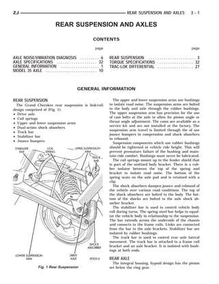
  • 1. ZJ REAR SUSPENSION AND AXLES 3-1 REAR SUSPENSION AND AXLES CONTENTS page page AXLE NOISE/VIBRATION DIAGNOSIS . . . . . . . . . 6 REAR SUSPENSION . . . . . . . . . . . . . . . . . . . . . . 3 AXLE SPECIFICATIONS . . . . . . . . . . . . . . . . . . . 32 TORQUE SPECIFICATIONS . . . . . . . . . . . . . . . . 32 GENERAL INFORMATION . . . . . . . . . . . . . . . . . . 1 TRAC-LOK DIFFERENTIAL . . . . . . . . . . . . . . . . . 27 MODEL 35 AXLE . . . . . . . . . . . . . . . . . . . . . . . . 10 GENERAL INFORMATION REAR SUSPENSION The upper and lower suspension arms use bushings The Grand Cherokee rear suspension is link/coil to isolate road noise. The suspension arms are bolted design comprised of (Fig. 1); to the body and axle through the rubber bushings. • Drive axle The upper suspension arm has provision for the use • Coil springs of cam bolts at the axle to allow for pinion angle or • Upper and lower suspension arms thrust angle adjustment. The cams are available as a service kit and are not installed at the factory. The • Dual-action shock absorbers suspension arm travel is limited through the of use • Track bar jounce bumpers in compression and shock absorbers • Stabilizer bar in rebound. • Jounce bumpers Suspension components which use rubber bushings should be tightened at vehicle ride height. This will prevent premature failure of the bushing and main- tain ride comfort. Bushings must never be lubricated. The coil springs mount up in the fender shield that is part of the unitized body bracket. There is a rub- ber isolator between the top of the spring and bracket to isolate road noise. The bottom of the spring seats on the axle pad and is retained with a clip. The shock absorbers dampen jounce and rebound of the vehicle over various road conditions. The top of the shock absorbers are bolted to the body. The bot- tom of the shocks are bolted to the axle shock ab- sorber bracket. The stabilizer bar is used to control vehicle body roll during turns. The spring steel bar helps to equal- ize the vehicle body in relationship to the suspension. The bar extends across the underside of the chassis and connects to the frame rails. Links are connected from the bar to the axle brackets. Stabilizer bar are isolated by rubber bushings. The track bar is used to control rear axle lateral movement. The track bar is attached to a frame rail bracket and an axle bracket. It is isolated with bush- ings at both ends. REAR AXLE The integral housing, hypoid design has the pinion Fig. 1 Rear Suspension set below the ring gear.
  • 2. 3-2 REAR SUSPENSION AND AXLES ZJ The axles are equipped with A.B.S. brake systems. During straight ahead driving, the differential pin- The A.B.S. tone rings are pressed onto the axle shaft ion gears do not rotate on the pinion mate shaft. This near the hub flange. For additional information on occurs because input torque applied to the gears is the A.B.S. system refer to Group 5, Brakes. divided and distributed equally between the two side The Model 35 axle has the assembly part number gears. As a result, the pinion gears revolve with the and gear ratio listed on a tag. The tag is attached to pinion mate shaft but do not rotate around it (Fig. 3). When turning corners, the outside wheel must the housing cover (Fig. 2). Build date identification codes are stamped on the axle shaft tube cover side. The Model 35 axle is available with Trac-Lok™ (limited slip) differential as an option. Fig. 3 Differential Operation—Straight-Ahead Driving travel a greater distance than the inside wheel in or- der to complete a turn. This difference must be com- pensated for in order to prevent the wheels from scuffing and skidding through the turn. To accom- plish this, the differential allows the axle shafts to turn at unequal speeds (Fig. 4). In this instance, the input torque applied to the pinion gears is not di- vided equally. The pinion gears now rotate around the pinion mate shaft in opposite directions. This al- Fig. 2 Model 35 Differential Cover lows the side gear and axle shaft attached to the out- STANDARD DIFFERENTIAL OPERATION side wheel to rotate at a faster speed. The differential gear system divides the torque be- tween the axle shafts. It allows the axle shafts to ro- tate at different speeds when turning corners. Each differential side gear is splined to an axle shaft. The pinion gears are mounted on a pinion mate shaft and are free to rotate on the shaft. The pinion gear is fitted in a bore in the differential case and is positioned at a right angle to the axle shafts. In operation, power flow occurs as follows: • Pinion gear rotates the ring gear • Ring gear (bolted to the differential case) rotates the case • Differential pinion gears (mounted on the pinion mate shaft in the case) rotate the side gears • Side gears (splined to the axle shafts) rotate the shafts Fig. 4 Differential Operation—On Turns
  • 3. ZJ REAR SUSPENSION AND AXLES 3-3 REAR SUSPENSION INDEX page page Coil Spring . . . . . . . . . . . . . . . . . . . . . . . . . . . . . . . 4 Spring and Shock Diagnosis . . . . . . . . . . . . . . . . . . 4 Lower Suspension Arm . . . . . . . . . . . . . . . . . . . . . . 4 Stabilizer Bar . . . . . . . . . . . . . . . . . . . . . . . . . . . . . 3 Service Information . . . . . . . . . . . . . . . . . . . . . . . . . 3 Track Bar . . . . . . . . . . . . . . . . . . . . . . . . . . . . . . . . 3 Shock Absorber . . . . . . . . . . . . . . . . . . . . . . . . . . . 4 Upper Suspension Arm . . . . . . . . . . . . . . . . . . . . . . 4 SERVICE INFORMATION (2) It may be necessary to pry the axle assembly over to install the track bar. Install the track bar to CAUTION: Suspension components that use rubber the frame rail bracket. Loosely install the bolt and bushings should be tightened with the vehicle at flag nut (Fig. 1). normal ride height. If the springs are not at their (3) Remove the supports and lower the vehicle. normal ride position, vehicle ride comfort and han- (4) Tighten the track bar bolts 100 N⅐m (74 ft. lbs.) dling could be affected. Rubber bushings must torque. never be lubricated. STABILIZER BAR TRACK BAR REMOVAL (1) Raise and support the vehicle. Remove one REMOVAL wheel and tire. (1) Raise and support the vehicle. (2) Disconnect the stabilizer bar links from the (2) Remove the bolt and nut from the frame rail axle brackets (Fig. 2). bracket (Fig. 1). (3) Lower the exhaust by disconnecting the muffler and tail pipe hangers. (4) Disconnect the stabilizer bar from the links. (5) Disconnect the stabilizer bar clamps from the frame rails. Remove the stabilizer bar. Fig. 1 Rear Track Bar (3) Remove the bolt from the axle tube bracket (Fig. 1). Remove the track bar. INSTALLATION Fig. 2 Rear Stabilizer Bar (1) Install the track bar to the axle bracket and in- stall a new bolt (Fig. 1).
  • 4. 3-4 REAR SUSPENSION AND AXLES ZJ INSTALLATION (2) Remove the lower suspension arm nut and bolt (1) Position the stabilizer bar on the frame rail and at the axle bracket (Fig. 3). install the clamps and bolts. Ensure the bar is cen- (3) Remove the nut and bolt (Fig. 3) at the frame tered with equal spacing on both sides. Tighten the rail and remove the lower suspension arm. bolts to 54 N⅐m (40 ft. lbs.). (2) Install the links and grommets onto the stabi- INSTALLATION lizer bar and axle brackets (Fig. 2). Install the nuts (1) Position the lower suspension arm at the axle and tighten to 36 N⅐m (27 ft. lbs.) torque. bracket and frame rail bracket (Fig. 3). (3) Connect the muffler and tail pipe to their hang- (2) Install the bolts and finger tighten the nuts ers. (Fig. 3). (4) Install the wheel and tire. (3) Remove the supports and lower the vehicle. (4) Tighten the lower suspension arm nuts to 177 UPPER SUSPENSION ARM N⅐m (130 ft. lbs.) torque. REMOVAL SPRING AND SHOCK DIAGNOSIS (1) Raise and support the vehicle. A squeak noise from the shock absorber can be pro- (2) Remove the upper suspension arm nut and bolt duced if movement between the rubber bushings and at the axle bracket (Fig. 3). Remove the ABS wire the metal occurs. This noise can usually be corrected bracket from the arm. by tightening the attachment nuts. If the squeak (3) Remove the nut and bolt (Fig. 3) at the frame noise persists, inspect for damaged and worn bush- rail and remove the upper suspension arm. ings, and attaching components. Repair as necessary. The shock absorbers are not refillable or adjust- able. If a malfunction occurs, the shock absorber must be replaced. To test a shock absorber, hold it in an upright position and force the piston into and out of the cylinder four or five times. The action through- out each stroke should be smooth and even. SHOCK ABSORBER REMOVAL (1) Raise and support the vehicle. Position a hy- draulic jack under the axle to support it. (2) Remove the upper nut and retainer from the frame rail stud (Fig. 4). (3) Remove the lower nut and bolt from the axle bracket. Remove the shock absorber. INSTALLATION (1) Install the shock absorber on the upper frame rail stud. Install the shock absorber on the axle bracket (Fig. 4). Fig. 3 Upper and Lower Suspension Arms (2) Install the retainer and nut on the stud. Tighten the upper nut to 70 N⅐m (52 ft. lbs.) torque. INSTALLATION (3) Tighten the lower nut to 92 N⅐m (68 ft. lbs.) (1) Position the upper suspension arm at the axle torque. and frame rail (Fig. 3). (4) Remove the supports and lower the vehicle. (2) Install the bolts and finger tighten the nuts (Fig. 3). Install the ABS wire bracket onto the arm. COIL SPRING (3) Remove the supports and lower the vehicle. (4) Tighten the upper suspension arm nuts to 75 REMOVAL N⅐m (55 ft. lbs.) torque. (1) Raise and support the vehicle. Position a hy- draulic jack under the axle to support it. LOWER SUSPENSION ARM (2) Disconnect the stabilizer bar link and shock ab- sorber from the axle bracket. REMOVAL (3) Disconnect the track bar from the frame rail (1) Raise and support the vehicle. bracket.
  • 5. ZJ REAR SUSPENSION AND AXLES 3-5 INSTALLATION Inspect isolator the for damage or wear. Replace the isolator if necessary before installing spring. (1) Position the coil spring on the axle pad. Install the spring retainer and bolt (Fig. 4). Tighten the bolt to 22 N⅐m (16 ft. lbs.) torque. (2) Raise the axle into position until the spring seats in the upper mount. (3) Connect the stabilizer bar links and shock ab- sorbers to the axle bracket. Connect the track bar to the frame rail bracket. (4) Remove the supports and lower the vehicle. Fig. 4 Rear Coil Spring & Shock Absorber (4) Lower the axle until the spring is free from the upper mount seat. Remove the coil spring retainer bolt (Fig. 4) and remove the spring.
  • 6. 3-6 REAR SUSPENSION AND AXLES ZJ AXLE NOISE/VIBRATION DIAGNOSIS INDEX page page Driveline Snap . . . . . . .. . . . . . . . . . . . . . . . . . . . . 7 Low Speed Knock . . . . . . . . . . . . . . . . . . . . . . . . . . 7 Gear and Bearing Noise . . . . . . . . . . . . . . . . . . . . . 6 Rear Axle Alignment . . . . . . . . . . . . . . . . . . . . . . . . 7 General Information . . .. . . . . . . . . . . . . . . . . . . . . 6 Vibration . . . . . . . . . . . . . . . . . . . . . . . . . . . . . . . . . 7 Limited Slip Differential .. . . . . . . . . . . . . . . . . . . . . 7 GENERAL INFORMATION GEAR AND BEARING NOISE Axle bearing problem conditions are usually caused by: GEAR NOISE • Insufficient or incorrect lubricant Axle gear noise can be caused by insufficient lubri- • Foreign matter/water contamination cant. Incorrect backlash, tooth contact, or worn/dam- • Incorrect bearing preload torque adjustment aged gears can cause noise. When serviced, the bearings must be cleaned thor- Gear noise usually happens at a specific speed oughly. They should be dried with lint free shop tow- range. The range is 30 to 40 mph, or above 50 mph. els. Never spin bearings with compressed air. The noise can also occur during a specific type of driving condition. These conditions are acceleration, This will overheat them and brinell the bearing deceleration, coast, or constant load. surfaces. This will result in noisy operation af- When road testing, accelerate the vehicle to the ter repair. speed range where the noise is the greatest. Shift out Axle gear problem conditions are usually the result of gear and coast through the peak noise range. If of: the noise stops or changes greatly, check for insuffi- • Insufficient lubrication cient lubricant. Incorrect ring gear backlash, or gear • Incorrect or contaminated lubricant (water) damage can cause noise changes. • Overloading (excessive engine torque) Differential side and pinion gears can be checked • Incorrect clearance or backlash adjustment by turning the vehicle. They usually do not cause Insufficient lubrication is usually the result of a noise in straight ahead driving. These gears are housing cover leak. It can also be from worn axle loaded during vehicle turns. If noise does occur dur- shaft or pinion gear seals. Check for cracks or porous ing vehicle turns, the side or pinion gears could be areas in the housing or tubes. worn or damaged. A worn pinion gear mate shaft can Using the wrong lubricant will cause overheating also cause a snapping or a knocking noise. and gear failure. Gear tooth cracking and bearing spalling are indicators of this. BEARING NOISE Axle component breakage is most often the result The axle shaft, differential and pinion gear bear- of: ings can all produce noise when worn or damaged. • Severe overloading Bearing noise can be either a whining, or a growling • Insufficient lubricant sound. Pinion gear bearings have a constant pitch noise. • Incorrect lubricant This noise changes only with vehicle speed. Pinion • Improperly tightened components bearing noise will be higher because it rotates at a Common causes of overloading is from full throttle faster rate. Drive the vehicle and load the differen- acceleration. Overloading happens when towing tial. If bearing noise occurs the pinion rear bearing is heavier than recommended loads. Component break- the source of the noise. If the bearing noise is heard age can occur when the wheels are spun excessively. during a coast, front bearing is the source. Insufficient or incorrect lubricants contribute to Worn, damaged differential bearings usually pro- breakage through overheating. Loose differential duce a low pitch noise. Differential bearing noise is components can also cause breakage. similar to pinion bearing. The pitch of differential Incorrect bearing preload or gear backlash will not bearing noise is also constant and varies only with result in component breakage. Mis-adjustment will vehicle speed. produce enough noise to cause service repair before a Axle shaft bearings produce noise and vibration failure occurs. If a mis-adjustment condition is not when worn or damaged. The noise generally changes corrected, component failure can result. when the bearings are loaded. Road test the vehicle. Turn the vehicle sharply to the left and to the right.
  • 7. ZJ REAR SUSPENSION AND AXLES 3-7 This will load the bearings and change the noise (2) Attach a one inch long piece of masking tape at level. Where axle bearing damage is slight, the noise the center of each tire tread for use as reference marks. is usually not noticeable at speeds above 30 mph. (3) Rotate the rear wheels until both reference marks face the front of the vehicle. Measure the dis- LOW SPEED KNOCK tance between the outside edges of the two pieces of Low speed knock is generally caused by a worn tape. Record this measurement as the front of tire U-joint or by worn side gear thrust washers. A worn (FTR) measurement. pinion gear shaft bore will also cause low speed knock. (4) Rotate the rear wheels until both reference marks face the rear of the vehicle. Measure the dis- VIBRATION tance between the outside edges of the two pieces of Vibration at the rear of the vehicle is usually tape. Record this measurement as the rear of tire caused by a: (RTR) measurement. • Damaged drive shaft (5) Subtract the (RTR) measurement from the • Missing drive shaft balance weight (FTR) measurement to obtain the amount of wheel • Worn, out-of-balance wheels • Loose wheel lug nuts toe. The acceptable rear wheel toe-in position is 1/16 • Worn U-joint inch (1.6 mm) to 3/16 inch (4.8 mm) toe-out. • Loose spring U-bolts (6) Rotate the rear wheels until the reference • Loose/broken springs marks are facing downward. Measure the distance • Damaged axle shaft bearings between the outside edges of the two pieces of tape. • Loose pinion gear nut Record this measurement as the bottom of tire (BTR) • Excessive pinion yoke run out measurement. • Bent axle shaft (7) Average the (FTR) and the (RTR) distance mea- Check for loose or damaged front end components surements. Subtract the (BTR) measurement from or engine/transmission mounts. These components this average distance to obtain the camber. The ac- can contribute to what appears to be a rear end vi- ceptable amount of camber is 1/16 inch to 3/32 inch bration. Do not overlook engine accessories, brackets (1.6 to 2.4 mm). and drive belts. (FTR + RTR) DIVIDED BY 2 (TWO) MINUS All driveline components should be examined be- BTR EQUALS CAMBER fore starting any repair. If the (BTR) distance measurement is less Refer to Group 22, Wheels and Tires for additional than the average FTR and RTR distance mea- information. surement, the camber will be positive ( + ). If the (BTR) distance measurement is greater DRIVELINE SNAP than the average FTR and RTR distance, the A snap or clunk noise when the vehicle is shifted camber will be negative ( - ). into gear (or the clutch engaged), can be caused by: If the toe position or camber is not acceptable, a • High engine idle speed bent or deformed rear axle shaft is most likely the • Loose engine/transmission/transfer case mounts cause. • Worn U-joints • Loose spring mounts LIMITED SLIP DIFFERENTIAL • Loose pinion gear nut and yoke Under normal traction conditions, engine torque is • Excessive ring gear backlash • Excessive differential side gear to case clearance divided evenly. With low traction surfaces, engine The source of a snap or a clunk noise can be deter- torque is transferred to the wheel with the most tire mined with the assistance of a helper. Raise the ve- traction. When diagnosing a limited-slip differential hicle on a hoist with the wheels free to rotate. problem condition, the wheel with the least traction Instruct the helper to shift the transmission into can continue spinning. gear. Listen for the noise, a mechanics stethoscope is The most common problem is a chatter noise when helpful in isolating the source of a noise. turning corners. Check for incorrect or contaminated lubricant. Replace the gear lubricant if necessary. REAR AXLE ALIGNMENT • With Trac-Lok differentials add a container of MOPAR௡ Trac-Lok Lubricant. MEASUREMENT This will correct the condition in most instances. If The following procedure can be used to determine the chatter persists, clutch damage could have occurred. if abnormal rear tire tread wear is the result of a After changing the lubricant, drive the vehicle and bent or deformed rear axle shaft. make 10 to 12 slow, figure eight turns. This maneu- (1) Raise both rear wheels off the surface with a ver will pump lubricant through the clutches. frame contact hoist.
  • 8. 3-8 REAR SUSPENSION AND AXLES ZJ SERVICE DIAGNOSIS
  • 9. ZJ REAR SUSPENSION AND AXLES 3-9 SERVICE DIAGNOSIS (CONT’D)
  • 10. 3 - 10 REAR SUSPENSION AND AXLES ZJ MODEL 35 AXLE INDEX page page Axle Assembly Replacement . . . . . . . . . . . . . . . . . 10 Final Assembly . . . . . . . . . . . . . . . . . . . . . . . . . . . 26 Axle Shaft . . . . . . . . . . . . . . . . . . . . . . . . . . . . . . . 13 General Information . . . . . . . . . . . . . . . . . . . . . . . 10 Axle Shaft Seal and Bearing . . . . . . . . . . . . . . . . . 13 Lubricant Change . . . . . . . . . . . . . . . . . . . . . . . . . 11 Backlash and Contact Pattern Analysis . . . . . . . . . 23 Lubricant Specifications . . . . . . . . . . . . . . . . . . . . . 10 Cleaning/Inspection . . . . . . . . . . . . . . . . . . . . . . . . 16 Pinion Gear Depth Information . . . . . . . . . . . . . . . 17 Differential Assembly . . . . . . . . . . . . . . . . . . . . . . . 17 Pinion Measurement and Assembly . . . . . . . . . . . . 19 Differential Disassembly . . . . . . . . . . . . . . . . . . . . 14 Pinion Removal/Disassembly . . . . . . . . . . . . . . . . . 15 Differential Measurement and Installation . . . . . . . . 21 Pinion Shaft Seal Replacement . . . . . . . . . . . . . . . 11 Differential Removal . . . . . . . . . . . . . . . . . . . . . . . 14 GENERAL INFORMATION MIL-L-2105C and API GL 5 quality specifications. The housing for Model 35 rear axles consists of an MOPAR௡ Hypoid Gear Lubricant conforms to both of iron center casting with tubes extending from either these specifications. side. The tubes are pressed into and welded to the • Lubricant for standard Model 35 axle use ther- differential housing to form a one piece axle housing. mally stable SAE 80W-90 gear lubricant. The integral type housing, hypoid gear design has • Lubricant for Model 35 axle with Trailer Tow use the centerline of the pinion set below the centerline SAE 75W-140 SYNTHETIC gear lubricant. of the ring gear. • Trac-Lok (limited slip) differentials add 4 fluid oz. The axle has a fitting for a vent hose used to re- of friction modifier. lieve internal pressure caused by lubricant vaporiza- • The lubricant quantity is 56Ϯ1 fluid oz.. tion and internal expansion. Refer to Group 0, Lubrication and Maintenance for The axles are equipped with semi-floating axle additional information. shafts, meaning that loads are supported by the axle shaft and bearings. The axle shafts are retained by CAUTION: If axle is submerged in water, lubricant C-clips in the differential side gears. must be replaced immediately to avoid possible The axles are equipped with ABS brake sensors. premature axle failure. The sensors are attached to the brake backing plate assemblies and tone rings are pressed on the axle AXLE ASSEMBLY REPLACEMENT shaft. Use care when removing axle shafts as NOT to damage the tone wheel or the sensor. REMOVAL The removable cover provides a means for servicing (1) Raise and support the vehicle. the differential without removing the axle assembly. (2) Position a floor jack under the axle. The Model 35 axle has the assembly part number (3) Remove the wheels and tires. Remove the and gear ratio listed on a tag. The tag is attached to brake components from the axle, refer to Group 5, the housing cover. Build date identification codes are Brakes. stamped on the axle shaft tube cover side. (4) Disconnect the vent hose from the axle shaft The differential case is a one piece design. The dif- tube. ferential pinion mate shaft is retained with a (5) Mark the propeller shaft and yokes for installa- threaded roll pin. Differential bearing preload and tion alignment reference. Remove the propeller shaft. ring gear backlash is adjusted by the use of spacer (6) Disconnect stabilizer bar links. shims. The shims are located between the differential (7) Disconnect shock absorbers from axle. bearing cups and housing. Pinion bearing preload is (8) Disconnect track bar. set and maintained by the use of a collapsible spacer. (9) Disconnect upper and lower suspension arms For complete drive axle assembly removal from the axle brackets. and installation refer to Drive Axle Assembly (10) Lower the axle with the jack. Replacement in this Group. INSTALLATION LUBRICANT SPECIFICATIONS Have the springs supporting the weight of the Multi-purpose, hypoid gear lubricant should be vehicle when the arms and track bar fasteners used for Model 35 axle. The lubricant should have are being torqued. If the springs are not at
  • 11. ZJ REAR SUSPENSION AND AXLES 3 - 11 their normal ride position, vehicle ride comfort and handling could be affected. (1) Raise the axle with a floor jack and align coil springs. (2) Position the upper and lower suspension arms on the axle brackets. Install nuts and bolts, DO NOT TORQUE BOLTS AT THIS TIME. (3) Install track bar and attachment bolts, DO NOT TORQUE BOLTS AT THIS TIME. (4) Install shock absorber and tighten nuts to 60 N⅐m (44 ft. lbs.) torque (5) Install stabilizer bar link and tighten nuts to 36 N⅐m (27 ft. lbs.) torque (6) Install brake components refer to Group 5 Brakes. (7) Install axle vent hose (8) Align propeller shaft and pinion yoke reference marks. Install U-joint straps and bolts tighten to 19 N⅐m (14 ft. lbs.) torque (9) Install the wheels and tires. (8) Check and add gear lubricant if needed. (9) Remove support and lower the vehicle. Fig. 1 Typical Housing Cover With Sealant (10) Tighten lower suspension arms bolts to 177 Trac-Lok (limited slip) Differentials; A con- N⅐m (130 ft. lbs.) torque. tainer of Trac-Lok Lubricant (friction modifier) (11) Tighten upper suspension arms bolts to 75 should be added after repair service or a lubricant N⅐m (55 ft. lbs.) torque. change. (12) Tighten track bar bolts to 100 N⅐m (74 ft. lbs.) (9) Install the fill hole plug and lower the vehicle. torque. LIMITED SLIP DIFFERENTIAL vehicles should be road tested by making 10 to 12 slow figure eight LUBRICANT CHANGE turns. This maneuver will pump the lubricant The gear lubricant will drain quicker if the vehicle through the clutch discs to eliminate a possible chat- has been recently driven. ter noise complaint. (1) Raise and support the vehicle. (2) Remove the lubricant fill hole plug from the dif- PINION SHAFT SEAL REPLACEMENT ferential housing cover. (3) Remove the differential housing cover and REMOVAL drain the lubricant from the housing. (1) Raise and support the vehicle. (4) Clean the housing cavity with a flushing oil, (2) Remove wheel and tire assemblies light engine oil or lint free cloth. Do not use water, (3) Mark the drive shaft yoke and pinion yoke for steam, kerosene or gasoline for cleaning. installation alignment reference. (5) Remove the sealant from the housing and cover (4) Remove the drive shaft from the yoke. surfaces. Use solvent to clean the mating surfaces. (5) Rotate the pinion gear three or four times. (6) Apply a bead of MOPAR௡ Silicone Rubber Seal- Make sure brakes are not dragging during this ant to the housing cover (Fig. 1). Allow the sealant procedure. to cure for a few minutes. (6) Measure the amount of torque (in Newton Install the housing cover within 5 minutes af- meters or inch pounds) necessary to rotate the pinion ter applying the sealant. If not installed the gear with a torque wrench. Note the torque for in- sealant must be removed and another bead ap- stallation reference. It must be known to properly plied. adjust the pinion gear bearing preload torque (7) Install the cover and any identification tag. after seal installation. Tighten the cover bolts in a criss-cross pattern to 41 (7) Remove the pinion yoke nut and washer. Use N⅐m (30 ft. lbs.) torque. Remover C-452 and Wrench C-3281 to remove the (8) Refill the differential with MOPAR௡ Hypoid pinion yoke (Fig. 2). Gear Lubricant to bottom of fill plug hole. (8) Mark the positions of the yoke and pinion gear for installation alignment reference.
  • 12. 3 - 12 REAR SUSPENSION AND AXLES ZJ Fig. 2 Pinion Yoke Removal (9) Use Remover 7794A and slide hammer to re- move the pinion gear seal (Fig. 3). Fig. 4 Pinion Seal Installation (5) Rotate the shaft with the torque wrench and note the torque. The required preload is equal to the amount at removal plus 0.56 N⅐m (5 in. lbs.). (6) Use Flange Wrench C-3281 to retain the yoke and shaft (Fig. 5). Tighten the shaft nut in very small increments. Fig. 3 Seal Removal INSTALLATION (1) Apply a light coating of gear lubricant on the lip of pinion seal. Install seal with Installer D-163 and Handle C-4171 (Fig. 4). (2) Align the installation reference marks and in- stall yoke on the pinion gear with Installer W-162D. (3) Install a new nut on the pinion gear. Tighten the nut only enough to remove the shaft end play. CAUTION: Exercise care during bearing preload torque adjustment. Do not overtighten, or loosen and then re-tighten the nut. Do not exceed the bear- ing preload torque. The collapsible preload spacer on the pinion shaft will have to be replaced. The bearing preload torque will be re-adjusted after- Fig. 5 Tightening Pinion Shaft Nut ward. (7) Continue tightening the shaft nut in small in- crements until the correct bearing preload torque is (4) Install a socket and inch pound torque wrench attained. on the pinion nut.
  • 13. ZJ REAR SUSPENSION AND AXLES 3 - 13 (8) Align the installation reference marks and at- tach the drive shaft to the yoke. (9) Add API grade GL 5 hypoid gear lubricant to the differential housing, if necessary. (10) Install wheel and tire assemblies (11) Lower the vehicle. AXLE SHAFT REMOVAL (1) Raise and support the vehicle. (2) Remove the wheel and tire. (3) Remove the brake drum. If equipped with rear disc brakes refer to Group 5 Brakes for procedure. (4) Clean all the foreign material from housing cover area. Fig. 7 Axle Shaft C-Clip Lock (5) Loosen the housing cover bolts. Drain the lubri- Use care to prevent the shaft splines from dam- cant from the housing and the axle shaft tubes. Re- aging the axle shaft seal lip. move the housing cover. (2) Insert the C-clip lock in the end of the axle (6) Rotate the differential case so that the pinion shaft. Push the axle shaft outward to seat the C-clip mate gear shaft lock screw is accessible. Remove the lock in the side gear. lock screw and the pinion mate gear shaft from the (3) Insert the mate shaft into the case and through case (Fig. 6). the thrust washers and pinion gears. Align the hole in shaft with the hole in the differential case and in- stall the lock screw with Loctite௡ on the threads. Tighten the screw to 19 N⅐m (14 ft. lbs.) torque. (4) Install the cover and add fluid. Refer to the Drain and Refill in this section. AXLE SHAFT SEAL AND BEARING REMOVAL (1) Remove the axle shaft. Refer to the Removal procedures in this Section. (2) Remove the axle shaft seal from the end of the axle shaft tube with a small pry bar. (3) Remove the bearing if it appears damaged. The seal and bearing can be removed at the same time with the bearing removal tool. Fig. 6 Mate Shaft Lock Screw (4) Remove the axle shaft bearing from the tube (7) Force the axle shaft in toward the center of the (Fig. 8) with Bearing Removal Tool Set 6310 (T.Ar vehicle. Remove the axle shaft C-clip lock from the 960-02). axle shaft (Fig. 7). (5) Inspect the axle shaft tube bore for roughness (8) Remove the axle shaft. Use care to prevent and burrs. Remove as necessary. damage to the axle shaft bearing and seal, which will CAUTION: Inspect the housing bore for burrs and remain in the axle shaft tube. remove if they exist. (9) Inspect the roller bearing contact surface on the axle shaft for signs of brinelling, spalling and pit- ting. INSTALLATION (10) If any of these conditions exist, the axle shaft Do not install the original axle shaft seal. Al- and bearing must be replaced. ways install a new seal. (1) Wipe the bore in the axle shaft tube clean. INSTALLATION (2) Install axle shaft bearing with Installer 6436 (1) Lubricate the bearing bore and seal lip with and Handle C-4171. Ensure part number on the gear lubricant. Insert the axle shaft through the seal, bearing must go against the Installer. bearing, and engage it with the side gear splines.
  • 14. 3 - 14 REAR SUSPENSION AND AXLES ZJ Fig. 10 Bearing Cap Identification Fig. 8 Axle Shaft Bearing Removal Tool (3) Install the new axle shaft seal (Fig. 9) with In- staller 6437 and Handle C-4171. Fig. 11 Spread Differential Housing ential housing. Attach Dial Indicator to housing pilot stud. Load the indicator plunger against the opposite side of the housing (Fig. 11) and zero the indicator. CAUTION: Do not spread over 0.38 mm (0.015 in). If the housing is over-separated, it could be distorted Fig. 9 Axle Shaft Seal Installation or damaged. (4) Install the Axle Shaft. Refer to the installation procedure. (5) Separate the housing enough to remove the case from the housing. Measure the distance with the DIFFERENTIAL REMOVAL dial indicator (Fig. 11). To service the differential the axle shafts must be (6) Remove the dial indicator. removed. Refer to the removal procedures in this (7) Pry the differential case loose from the housing. Group. To prevent damage, pivot on housing with the end of (1) Note the installation reference letters the pry bar against spreader (Fig. 12). stamped on the bearing caps and housing ma- (8) Remove the case from housing. Mark or tag chined sealing surface (Fig. 10). bearing cups and outboard shim/spacer (selected (2) Remove the differential bearing caps. thickness) indicating which side they were removed. (3) Position Spreader W-129B with the tool dowel Remove spreader from housing. pins seated in the locating holes (Fig. 11). Install the holddown clamps and tighten the tool turnbuckle fin- DIFFERENTIAL DISASSEMBLY ger-tight. (1) Remove the bearings from the differential case with (4) Install a pilot stud at the left side of the differ- Press C-293PA, Plug SP3289, Adapter C-293-18 (Fig. 13).
  • 15. ZJ REAR SUSPENSION AND AXLES 3 - 15 Fig. 14 Ring Gear Removal (3) Rotate the differential side gears and remove the pinion mate gears and thrust washers (Fig. 15). Fig. 12 Differential Removal Place adapter rings so they do not damage the bearing cage. Fig. 15 Pinion Mate Gear Removal (4) Remove the differential side gears and thrust washers. (5) Remove the case from the vise. PINION REMOVAL/DISASSEMBLY (1) Remove the pinion yoke nut and washer. Use Remover C-452 and Wrench C-3281 to remove the pinion yoke (Fig. 16). (2) Remove the pinion gear from housing (Fig. 17). Fig. 13 Differential Bearing Removal Catch the pinion with your hand to prevent it from (2) Clamp the differential case in a vise equipped falling and being damaged. with soft jaws. Remove and discard the ring gear (3) Remove the pinion gear seal with a slide ham- bolts. Tap the ring gear with a rawhide or plastic mer or pry out with bar. mallet and remove (Fig. 14).
  • 16. 3 - 16 REAR SUSPENSION AND AXLES ZJ Fig. 16 Pinion Yoke Removal Fig. 18 Front Bearing Cup Removal Fig. 17 Remove Pinion Gear (4) Remove front bearing, and oil slinger if equipped. (5) Remove the front pinion bearing cup with Re- mover D-147 and Handle C-4171 (Fig. 18). Fig. 19 Rear Bearing Cup Removal (6) Remove the rear bearing cup from housing (Fig. 19). Use Remover D-148 and Handle C-4171. CLEANING/INSPECTION (7) Remove the collapsible preload spacer (Fig. 20). Wash differential components with cleaning solvent (8) Remove the inner bearing from the pinion with and dry with compressed air. Do not steam clean Puller C-293PA and Adapter C-293-39 (Fig. 21). the differential components. Place adapter rings so they do not damage Wash bearings with solvent and towel dry. DO the bearing cage. NOT spin bearings with compressed air. Cup and (9) Remove the depth shims from the pinion gear bearing must be replaced as a matched sets shaft. Record the thickness of the depth shims. only. Clean the axle shaft tubes and oil channel in hous- ing with a stiff wire and clean cloth. Inspect for;
  • 17. ZJ REAR SUSPENSION AND AXLES 3 - 17 • Wear and damage to pinion gear mate shaft, pin- ion gears, side gears and thrust washers. Replace as a matched set only. • Ring and pinion gear for worn and chipped teeth. • Ring gear for damaged bolt threads. Replaced as a matched set only. • Pinion yoke for cracks, worn splines, pitted areas, and a rough/corroded seal contact surface. Repair or replace as necessary. • Preload shims for damage and distortion. Install new shims if necessary. DIFFERENTIAL ASSEMBLY (1) Install the following components in the differ- ential case. • Differential side gears and thrust washers • Pinion gears and thrust washers • Pinion gear mate shaft (align holes in shaft and case) (2) Lubricate all differential components with hy- poid gear lubricant. Fig. 20 Collapsible Preload Spacer PINION GEAR DEPTH INFORMATION Ring and pinion gears are supplied as matched sets only. The identifying numbers for the ring and pinion gear are etched into the face of each gear (Fig. 22). A plus (+) number, minus (-) number or zero (0) is etched into the face of the pinion gear. This number is the amount (in thousandths of an inch) the depth varies from the standard depth setting of a pinion etched with a (0). The standard setting from the cen- terline of the ring gear to the back face of the pinion is 96.8 mm (3.813 inches) for Model 35 axles (Fig. 23). The standard depth provides the best teeth con- tact pattern. Fig. 21 Inner Bearing Removal • Smooth appearance with no broken/dented sur- faces on the bearing rollers or the roller contact sur- faces. • Bearing cups must not be distorted or cracked. • Machined surfaces should be smooth and without Fig. 22 Pinion Gear ID Numbers any raised edges. • Raised metal on shoulders of cup bores should be removed with a hand stone.
  • 18. 3 - 18 REAR SUSPENSION AND AXLES ZJ THE BUTTON END ON THE PINION GEAR HEAD IS NO LONGER A MACHINED-TO-SPECIFI- CATIONS SURFACE. DO NOT USE THIS SUR- FACE FOR PINION DEPTH SET-UP OR CHECKING (Fig. 23). Fig. 23 Pinion Gear Head Fig. 24 Shim Locations Compensation for pinion depth variance is achieved Note where Old and New Pinion Marking columns with select shims. In production the shims are placed intersect. Intersecting figure represents plus or mi- between the pinion gear and the inner pinion bearing nus amount needed. cone. For service the shims are placed under the in- For example, if old pinion is plus (+) 1 and the new ner pinion bearing cup (Fig. 24). pinion is minus (-) 3, intersecting figure is (+) 0.004 If a new gear set is being installed, note the inch (0.10mm). Add this amount to the original shim. depth variance etched into both pinion gears. Or if the old pinion is (-) 3 and the new pinion is (-) Add or subtract the thickness of the original 2, intersecting figure is (-) 0.001 inch (0.025mm). depth shims to compensate for the difference in depth variances. Refer to the Depth Variance Subtract this amount from original shim. Refer to charts. the Pinion Gear Depth Variance Chart. PINION GEAR DEPTH VARIANCE
  • 19. ZJ REAR SUSPENSION AND AXLES 3 - 19 PINION MEASUREMENT AND ASSEMBLY PINION GEAR DEPTH MEASUREMENT Pinion gear depth measurement is necessary when; • Axle housing or differential case is replaced • Pinion select shim pack is unknown • Ring and pinion gears are replaced Compensation for pinion depth variance is achieved with select shims. In production the shims are placed between the pinion gear and the inner pinion bearing cone. For service the shims are placed under the in- ner pinion bearing cup. Measurements are taken with pinion cups and pin- ion bearings installed in housing. Take measure- ments with Pinion Gauge Set 6774, Pinion Block 6735 and Dial Indicator C-3339 (Fig. 25). Fig. 26 Pinion Height Block Fig. 27 Gauge Tools In Housing Fig. 25 Pinion Gear Depth Gauge Tools (1) Assemble Pinion Gauge Set, Pinion Block and pinion bearings. Install assembly into differential pinion gear bore and hand tighten cone (Fig. 26). (2) Place Arbor Disc 6732 on Arbor D-115-3 and po- sition in the bearing cradles (Fig. 27). Install differ- ential bearing caps on Arbor Discs and tighten caps snug only. Arbor Discs have different steps to fit other axle sizes. Pick correct size step for axle being serviced. (3) Firmly place Scooter Block and Dial Indicator Fig. 28 Pinion Gear Depth Measurement on pinion height block tool and zero the dial indicator The plunger travel distance indicated, plus or pointer. minus the variance etched in the gear is the re- (4) Slide the Scooter Block across the arbor while quired thickness for the depth shims. observing indicator (Fig. 28). Record the longest travel distance, whether inward (-) or outward (+), (5) Measure the thickness of each depth shim with indicated by the pointer. a micrometer and combine the shims necessary for
  • 20. 3 - 20 REAR SUSPENSION AND AXLES ZJ total required shim pack thickness. Include oil (3) Install pinion front bearing, oil slinger. Apply a slinger or baffle thickness with the total shim light coating of gear lubricant on the lip of pinion pack thickness. seal. Install seal with Installer D-163 and Handle (6) Remove the measurement tools from the differ- C-4171 (Fig. 31). ential housing. PINION GEAR ASSEMBLY/INSTALLATION (1) Place the depth shims (and baffle if equipped) in the pinion gear rear bearing bore. Install the bear- ing cup with Installer D-146 and Driver Handle C-4171 (Fig. 29). Ensure cup is correctly seated. Fig. 31 Pinion Seal Installation (4) Install the rear bearing (and slinger if used) on the pinion gear with Installer W-262 (Fig. 32). Fig. 29 Pinion Rear Bearing Cup Installation (2) Install the pinion front bearing cup with In- staller D-130 and Handle C-4171 (Fig. 30). Fig. 32 Rear Pinion Bearing Installation Fig. 30 Pinion Front Bearing Cup Installation
  • 21. ZJ REAR SUSPENSION AND AXLES 3 - 21 (5) Install a new collapsible preload spacer on pin- CAUTION: Never loosen pinion gear nut to decrease ion shaft (Fig. 33). pinion gear bearing preload torque and never exceed specified preload torque. If preload torque is exceeded a new collapsible spacer must be installed. The torque sequence will have to be repeated. (9) Use Flange Wrench C-3281 to retain the yoke (Fig. 35). Slowly tighten the nut in small increments until the rotating torque is achieved. Measure the preload torque frequently to avoid over-tight- ening the nut. The maximum pinion nut torque is 475 N⅐m (350 ft. lbs.). Fig. 33 Collapsible Preload Spacer (6) Install pinion gear into differential housing. (7) Install yoke with Installer W-162D and Wrench C-3281 (Fig. 34). Fig. 35 Tightening Pinion Nut (10) Check bearing preload torque with an inch pound torque wrench (Fig. 36). The torque necessary to rotate the pinion gear should be; • Original Bearings — 1 to 3 N⅐m (10 to 20 in. lbs.) • New Bearings — 1.7 to 3.9 N⅐m (15 to 35 in. lbs.) DIFFERENTIAL MEASUREMENT AND INSTALLATION DIFFERENTIAL SHIM PACK MEASUREMENT (1) Install the bearings on the hub with Installer C-3716A and Driver Handle C-4171. (2) Match each bearing cup with bearing (original). Install the cups on the bearings. (3) Install the differential case in the housing. (4) Install the outboard shim/spacer (selected thick- Fig. 34 Pinion Yoke Installation ness) on each side between bearing cup and housing (8) Install the yoke washer and a new nut on the (Fig. 37). Use 0.142 in. (3.6 mm) as a starting point, pinion gear. Tighten nut to 271 N⅐m (200 ft lbs.) shim/spacers are available in various thicknesses. min. Do not over-tighten. (5) Install the marked bearing caps in their correct positions. Install and snug the bolts.
  • 22. 3 - 22 REAR SUSPENSION AND AXLES ZJ Fig. 38 Shim Measurement Fig. 36 Check Pinion Gear Torque The differential bearings must be preloaded to compensate for heat and load during operation. (10) Add an additional 0.004 - inch (0.1 - mm) to each outboard shim/spacer for bearing preload. RING GEAR INSTALLATION (1) Invert the differential case and start two ring gear bolts. This will provide case-to-ring gear bolt hole alignment. (2) Install new ring gear bolts and alternately tighten to 95-122 N⅐m (70-90 ft. lbs.) torque (Fig. 39). Fig. 37 Differential Bearing Shim Installation (6) Attach a dial indicator to the housing. Position the indicator plunger so that it contacts the ring gear mating surface (Fig. 38). (7) Pry the differential case to one side and zero the dial indicator pointer. (8) Pry the differential case to the opposite side and record indicator reading. Reading is additional shim thickness needed for zero end play. For exam- ple, if reading was 0.008 inch (0.20 mm), an addi- tional 0.004 inch (0.10 - mm) thick shim will be Fig. 39 Ring Gear Bolt Installation needed at each side zero end play. (9) Install zero end-play shims on each side of case.
  • 23. ZJ REAR SUSPENSION AND AXLES 3 - 23 DIFFERENTIAL INSTALLATION (1) Position Spreader W-129B with the tool dowel pins seated in the locating holes (Fig. 40). Install the holddown clamps and tighten the tool turnbuckle fin- ger-tight. Fig. 40 Spread Differential Housing Fig. 41 Differential Installation (2) Install a pilot stud at the left side of the differ- ential housing. Attach Dial Indicator to housing pilot stud. Load the indicator plunger against the opposite side of the housing (Fig. 40) and zero the indicator. CAUTION: Do not spread over 0.38 mm (0.015 in). If the housing is over-separated, it could be distorted or damaged. (3) Separate the housing enough to install the case in the housing. Measure the distance with the dial indicator (Fig. 40). (4) Remove the dial indicator. (5) Install differential and outboard shim/spacer (selected thickness) in housing. (6) Install case in the housing. Tap the differential case to ensure the bearings are fully seated (Fig. 41). Fig. 42 Differential Bearing Cap Reference Letters Remove the spreader. SHIM PACK THICKNESS, EXCESSIVE BEAR- (7) Install the bearing caps at their original loca- ING PRELOAD AND DAMAGE WILL OCCUR. tions (Fig. 42). Tighten the bearing cap bolts to 77 The ring gear teeth contact patterns will show if N⅐m (57 ft. lbs.) torque. the pinion gear depth shim(s) have the correct thick- ness. It will also show if the ring gear backlash has BACKLASH AND CONTACT PATTERN ANALYSIS been adjusted correctly. The backlash must be main- (1) Rotate assembly several revolutions to seat tained within the specified limits until the correct bearings. Measure backlash at three equally spaced tooth contact patterns are obtained. locations around the perimeter of the ring gear with (2) Apply a thin coat of hydrated ferric oxide, to a dial indicator (Fig. 43). the ring gear teeth. The ring gear backlash must be within 0.12 - (3) Rotate the ring gear one complete revolution in 0.20 mm (0.005 - 0.008 inch). It cannot vary both directions while a load is being applied. Insert a more than 0.05 mm (0.002 inch) between the pry bar between the differential housing and the case points checked. flange. This action will produce distinct contact pat- If backlash must be adjusted, spacers are available terns on both the drive side and coast side of the ring in various thicknesses. Adjust the backlash accord- gear teeth. ingly (Fig. 44). DO NOT INCREASE THE TOTAL
  • 24. 3 - 24 REAR SUSPENSION AND AXLES ZJ Fig. 43 Ring Gear Backlash Measurement (4) Note patterns in compound. Refer to (Fig. 45) for interpretation of contact patterns and adjust ac- cordingly. Fig. 44 Backlash Shim Adjustment
  • 25. ZJ REAR SUSPENSION AND AXLES 3 - 25 Fig. 45 Gear Tooth Contact Patterns
  • 26. 3 - 26 REAR SUSPENSION AND AXLES ZJ FINAL ASSEMBLY (1) Install the axle shafts. Refer to Axle Shaft In- stallation within this group. (2) Scrape the residual sealant from the housing and cover mating surfaces. Clean the mating surfaces with mineral spirits. Apply a bead of MOPAR௡ Sili- cone Rubber Sealant on the housing cover (Fig. 46). Allow the sealant to cure for a few minutes. Install the housing cover within 5 minutes af- ter applying the sealant. If not installed the sealant must be removed and another bead ap- plied. (3) Install the cover on the differential with the at- taching bolts. Install the identification tag. Tighten the cover bolts to 41 N⅐m (30 ft. lbs.) torque. CAUTION: Overfilling the differential can result in the lubricant foaming and overheating. (4) Refill the differential housing with the specified quantity of MOPAR௡ Hypoid Gear Lubricant. (5) Install the fill hole plug if used and tighten to Fig. 46 Typical Housing Cover With Sealant 34 N⅐m (25 ft. lbs.) torque. Axles with rubber plug will snap into place.
  • 27. ZJ REAR SUSPENSION AND AXLES 3 - 27 TRAC-LOK DIFFERENTIAL OPERATION In a conventional differential, the torque applied to the ring gear is transmitted to the axle shafts through the differential gears. During normal opera- tion, the torque transmitted to each wheel is equal at all times. However, if one wheel spins, the opposite wheel will generate only as much torque as the spin- ning wheel. In the Trac-Lok differential, part of the ring gear torque is transmitted through clutch packs. The clutch packs contain multiple disc. The clutch will have radial grooves on the plates, and concentric grooves on the discs or bonded fiber material that is smooth appearance. In operation, the Trac-Lok clutches are engaged by two concurrent forces. The first being preload force exerted through Belleville spring washers contained in the clutch packs. The second from separating forces generated by the side gears as torque is ap- plied through the ring gear (Fig. 1). The Trac-Lok design provides differential action needed for turning corners and for driving straight ahead. However, when one wheel looses traction, the clutch packs transfer additional torque to the wheel having the most traction. Trac-Lok differentials resist wheel spin on bumpy roads and provide more pulling power when one wheel looses traction. Pulling power is provided continuously until both wheels loose trac- tion. If both wheels slip due to unequal traction, Fig. 1 Limited Slip Differential Operation—Both Trac-Lok operation is normal. In extreme cases of dif- Wheels Driving ferences of traction, the wheel with the least traction REAR WHEELS MUST BE RAISED AND THE VEHI- may spin. CLE SUPPORTED. A LIMITED SLIP AXLE CAN EX- ERT ENOUGH FORCE (IF ONE WHEEL IS IN NOISE DIAGNOSIS CONTACT WITH THE SURFACE) TO CAUSE THE If a noise occurs when turning corners, the most VEHICLE TO MOVE. probable cause is incorrect or contaminated lubri- cant. Before removing the Trac-Lok unit for repair, The differential can be tested without removing the drain, flush and refill the axle with the specified lu- differential case by measuring rotating torque. Make bricant. Refer to Lubricant change in this Group. sure brakes are not dragging during this measure- A container of Trac-Lok Lubricant (friction modi- ment. fier) should be added after repair service or a lubri- (1) Engine of, transmission in neutral, and parking cant change. brake off. Vehicles with a limited slip differential should be (2) Place blocks in front and rear of both front road tested by making 10 to 12 slow figure eight wheels. turns. This maneuver will pump the lubricant (3) Jack up one rear wheel until it is completely off through the clutch discs to eliminate a possible chat- the ground. ter or pop noise complaint. (4) Remove wheel and bolt Special Tool 6790 to Refer to Group 0, Lubrication and Maintenance for studs. additional information. (5) Use torque wrench on special tool to rotate DIFFERENTIAL TEST wheel and read rotating torque (Fig. 2). (6) If rotating torque is less than 22 N⅐m (30 ft. WARNING: WHEN SERVICING VEHICLES WITH A lbs.) or more than 271 N⅐m (200 ft. lbs.) on either LIMITED SLIP DIFFERENTIAL DO NOT USE THE EN- wheel the unit should be service. GINE TO TURN THE AXLE AND WHEELS. BOTH
  • 28. 3 - 28 REAR SUSPENSION AND AXLES ZJ Fig. 2 Trac-Loc Test DIFFERENTIAL OVERHAUL The Trac-Lok (limited-slip) differential components are illustrated in (Fig. 3). Refer to this illustration during repair service. Fig. 4 Axle Shaft As Holding Fixture DISASSEMBLY Service to the Trac-Lok differential requires the use of Tool Set C-4487 (J-23781). Refer to Model 35 Axle section in this Group for Differential Removal and Installation. (1) Clamp one axle shaft in a vise equipped with soft jaws (Fig. 4). Fig. 3 Trac-Lok Differential Components
  • 29. ZJ REAR SUSPENSION AND AXLES 3 - 29 (2) Position the differential case on the axle shaft (Fig. 5). Place shop towels under the differential to avoid damage during removal of the ring gear (Fig. 5). Fig. 7 Mate Shaft Lock Screw Fig. 5 Differential Case On Shaft (3) Remove and discard the ring gear bolts. Tap the ring gear with a rawhide or plastic mallet and re- move (Fig. 6). Fig. 8 Mate Shaft Removal Fig. 6 Ring Gear Removal (3) Remove the pinion gear mate shaft lock screw (Fig. 7). (5) Remove the pinion gear mate shaft with a drift and hammer (Fig. 8). (6) Install and lubricate Step Plate C-4487-1 (Fig. 9). (7) Assemble Threaded Adapter C-4487-3 into top side gear. Thread forcing Screw C-4487-2 into Fig. 9 Step Plate Tool Installation adapter until it becomes centered in adapter plate.
  • 30. 3 - 30 REAR SUSPENSION AND AXLES ZJ (8) Position a small screw driver in slot of Threaded Adapter C-4487-3 (Fig. 10) to prevent adapter from turning. Fig. 12 Pinion Gear Removal (12) Remove top side gear and clutch pack. Keep plates in correct order during removal (Fig. 13). (13) Remove case from fixture. Remove remaining Fig. 10 Threaded Adapter Installation clutch pack. (9) Tighten forcing screw tool enough to relieve clutch pack tension. Remove both pinion thrust washers (Fig. 11). Fig. 13 Side Gear & Clutch Disc Removal Fig. 11 Remove Pinion Thrust Washer (14) Remove clutch pack retaining clips. Mark each (10) Loosen the forcing screw tool until the clutch clutch pack for installation reference. pack tension is relieved. (11) Insert Turning Bar C-4487-4 in case. Rotate CLEANING AND INSPECTION case with tool until pinion gears can be removed (Fig. (1) Clean all components in cleaning solvent. Dry 12). components with compressed air.
  • 31. ZJ REAR SUSPENSION AND AXLES 3 - 31 (2) Inspect clutch pack plates for wear, scoring or damage. Replace both clutch packs if any one compo- nent in either pack is damaged. (3) Inspect side and pinion gears. Replace any gear that is worn, cracked, chipped or damaged. (4) Inspect differential case and pinion shaft. Re- place if worn or damaged. PRESOAK PLATES AND DISC Plates and dics with fiber coating (no groves or lines) must be presoaked in Friction Modifier before assembly. Soak plates and discs for a minimum of 20 minutes. Add remaining Friction Modifier to differen- tial after assembly. ASSEMBLY The clutch discs are replaceable as complete sets Fig. 15 Clutch Discs & Lower Side Gear Installation only. If one clutch disc pack is damaged, both packs must be replaced. Lubricate each component with gear lubricant be- fore assembly. (1) Assemble the clutch discs into packs secure disc packs with retaining clips (Fig. 14). (2) Position assembled clutch disc packs on the side gear hubs. Fig. 16 Upper Side Gear & Clutch Disc Pack Installation Adapter C-4487-3 into top side gear, insert forcing Screw C-4487-2. (8) Tighten forcing screw tool to compress clutch discs. (9) Install pinion gears. Rotate case with Turning Fig. 14 Clutch Disc Pack Bar C-4487-4. Make sure holes of pinion mate gears (3) Position case on axle fixture. are aligned with case. (4) Install clutch pack and side gear in lower bore (10) Tighten forcing screw to compress the (Fig. 15). Be sure clutch pack retaining clips re- Belleville plates. Lubricate and install pinion gear main in position and are seated in the case thrust washers with a small screw driver. pockets. (11) Remove forcing screw, threaded adapter and (5) Install lubricated Step Plate C-4487-1 on first step plate. Install pinion gear mate shaft, align holes clutch pack (Fig. 16). in shaft and case. (6) Install the upper side gear and clutch disc pack (12) Install the pinion mate shaft lock screw finger (Fig. 16). tight to hold shaft durning installation. (7) Hold assembly in position. Insert Threaded
  • 32. 3 - 32 REAR SUSPENSION AND AXLES ZJ If replacement gears and thrust washers were installed, it is not necessary to measure the gear backlash. Correct fit is due to close ma- chining tolerances during manufacture. (13) Invert the differential case and start two ring gear bolts. This will provide case-to-ring gear bolt hole alignment. (14) Install new ring gear bolts and alternately tighten to 95-122 N⅐m (70-90 ft. lbs.) torque (Fig. 17). (15) Lubricate all differential components with hy- poid gear lubricant. Fig. 17 Ring Gear Bolt Installation AXLE SPECIFICATIONS MODEL 35 AXLE Ring Gear Axle Type ...............................Semi-Floating Hypoid Diameter .......................................19.2 cm (7.562 in.) Lubricant................Thermally Stable SAE 80W-90 Backlash....................0.12-0.20 mm (0.005-0.008 in.) Lubricant Trailer Tow.............Synthetic 75W-140 Pinion Std. Depth ...................96.8 mm (3.813 in.) Lube Capacity ................................1.66 L (3.5 pts.) Pinion Bearing Preload Axle Ratio....................................................3.55 3.73 Original Bearing ..................1-2 N⅐m (10-20 in. lbs.) Diff. Brg. Preload......................0.1 mm (0.004 in.) New Bearing......................1.5-4 N⅐m (15-35 in. lbs.) Side Gear Clearance..............0-0.15 mm (0-0.006) TORQUE SPECIFICATIONS REAR SUSPENSION COMPONENTS Track Bar Frame Bracket Nut...................100 N⅐m (74 ft. lbs.) DESCRIPTION ................................................TORQUE Axle Bracket Bolt......................100 N⅐m (74 ft. lbs.) Shock Upper Nut .....................70 N⅐m (52 ft. lbs.) Shock Lower Nut.....................92 N⅐m (68 ft. lbs.) MODEL 35 AXLE Suspension Arm Upper Nuts ..............................................75 N⅐m (55 ft. lbs.) DESCRIPTION ................................................TORQUE Suspension Arm Lower Fill Hole Plug ...........................34 N⅐m (25 ft. lbs.) Nuts ..........................................177 N⅐m (130 ft. lbs.) Diff. Cover Bolt ........................41 N⅐m (30 ft. lbs.) Stabilizer Bar Bearing Cap Bolt .....................77 N⅐m (57 ft. lbs.) Clamp Bolt...................................54 N⅐m (40 ft. lbs.) Ring Gear Bolt .............95-122 N⅐m (70-90 ft. lbs.) Link Nut ......................................36 N⅐m (27 ft. lbs.)