SlideShare uma empresa Scribd logo
1 de 80
Baixar para ler offline
Partner for performance
www.gerwah.com
DE|EN
03|2013
Metallbalg- & Elastomerkupplungen,
Zwischenwellen
Metal Bellows & Servo-Insert Couplings,
Line Shafts
Wir sind für Sie da
A Global Presence For You
Die heutige RINGFEDER POWER TRANS­MISSION GMBH wurde
1922 in Krefeld / Deutschland als Patentverwertungsgesellschaft
für Reibungsfedern gegründet. Heute sind wir ein weltweiter An-
bieter für Spitzenprodukte der Antriebs- und Dämpfungstechnik.
Innovatives Denken in die Grenzbereiche des Möglichen zeichnet
uns aus und hilft uns, mit progressiven und günstigen Lösungen
den technischen Fortschritt unserer Kunden zu unterstützen.
The RINGFEDER POWER TRANSMISSION GMBH was founded
in 1922 in Krefeld, Germany to fabricate and promote Friction
Spring technology. Today we have expanded our offerings to top
power transmission and damping products. Innovative thinking sets
us apart and allows us to develop progressive and economical solu-
tions to support our customers.
2
Besondere Anforderungen erfordern besondere
Anstrengungen
Wir stehen Ihnen mit langjähriger Erfahrung und produktivem En-
gineering zur Verfügung - ob mit Standardprodukten oder auf indi-
viduelle Anfrage. Wir verste­hen Dinge wie außer­­gewöhnlich hohe
Belastbarkeit oder Montage-, Demontagefreund­lichkeit von Bauteilen,
aber auch die Senkung von Fertigungskosten als „Dienst am Kunden“
und entwickeln effiziente und technisch ausgereifte Lösungen.
Special applications require special solutions
Our extensive range of RINGFEDER POWER TRANSMISSION pro-
ducts can be applied to solve most applications. We don´t just sell, but
by understanding the individual requirements of our customers (e.g.
loads on the components, easy installation/removal capability and
reduction of production costs) assist you in every step with innovative
engineering to plan efficient and technically mature solutions.
3
Übersicht · Overview
Metallbalgkupplungen
Metal Bellows Couplings
Elastomerkupplungen
Servo-Insert Couplings
Zwischenwellen
Line Shafts
4
Inhalt · Content
02	 Imageseiten
	 Pages Corporate Image
04	 Übersicht · Overview
05	 Inhalt · Content
	 Metallbalgkupplungen
	 Metal Bellows Couplings
06	 Grundlagen · Basics
08	 Produktübersicht · Product Overview
10	 Baureihe/Series EKN
12	 Baureihe/Series DKN
14	 Baureihe/Series DKN/S
16	 Baureihe/Series PKN
18	 Baureihe/Series AKN
20	 Baureihe/Series AKN-H
22	 Baureihe/Series AKD
24	 Baureihe/Series AKD-H
26	 Baureihe/Series AK
28	 Baureihe/Series CKN
30	 Technische Hinweise · Technical Information
35	 Vorabinfo · Preview: ICL & SMC
	 Elastomerkupplungen
	 Servo-Insert Couplings
36	 Grundlagen · Basics
39	 Produktübersicht · Product Overview
40	 Baureihe/Series GWE 5102
42	 Baureihe/Series GWE 5103
44	 Baureihe/Series GWE 5103.1
46	 Baureihe/Series GWE 5107
48	 Baureihe/Series GWE 5104
50	 Baureihe/Series GWE 5106
52	 Baureihe/Series GWE 5112
54	 Technische Hinweise · Technical Information	
	 Zwischenwellen · Line Shafts
56	 Grundlagen · Basics
59	 Produktübersicht · Product Overview
60	 Baureihe/Series GWZ 5104.1
62	 Baureihe/Series GWZ 5106.1
64	 Baureihe/Series AKN-ZW
66	 Baureihe/Series AKN/H-ZW
	Montageanleitungen
	 Mounting Instructions
68	 Metallbalgkupplungen
	 Metal Bellows Couplings
70	 Elastomerkupplungen
	 Servo-Insert Couplings	
74	 Zwischenwellen · Line Shafts
	 Faxanfrage · Fax Inquiry
76	 Faxanfrage Kupplungen
	 Fax Inquiry Couplings
77	 Faxanfrage Zwischenwellen
	 Fax Inquiry Line Shafts
79	 Lieferprogramm · Delivery Program
	 RINGFEDER POWER TRANSMISSION
Alle technischen Daten und Hin­weise sind unverbindlich. Rechts­ansprüche können daraus
nicht abgeleitet werden. Der Anwender ist grundsätzlich verpflichtet zu prüfen, ob die dar-
gestellten Produkte seinen Anforderungen genügen. Änderungen, die dem technischen
Fortschritt dienen, behalten wir uns jederzeit vor. Mit Erscheinen dieses Kataloges werden
alle älteren Prospekte und Fragebögen zu den gezeigten Produkten ungültig.
All technical details and information are non-binding and cannot be used as a basis
for legal claims. The user is obligated to determine whether the represented products
meet his requirements. We reserve the right at all times to carry out modifications
in the interests of technical progress. Upon the issue of this catalogue all previous
brochures and questionnaires on the products displayed are no longer valid.
CAD - Daten erhältlich / CAD data available:
www.ringfeder.com
5
Metallbalgkupplungen Grundlagen
Spielfreie Metallbalgkupplungen
Characteristics of
Metal Bellows Couplings:
	 Backlash-free transmission of torque
	 High torsional stiffness, precision of transmission of
	 rotational angle
	 Different torsional stiffness
	 Compact design, low moment of inertia
	 Metal bellows made of stainless steel
	 Simple and safe assembly
	 Compensation of radial, axial and angular misalignment
	 Free of wear, maintenance-free, no downtimes
	 Not sensitive to temperatures between -30°C
	 and + 100°C,
	 Nominal torques between 0,1 – 5000 Nm
Typische Eigenschaften von
Metallbalgkupplungen:
	 Spielfreie Drehmomentübertragung
	 Hohe Verdrehsteife, exakte Übertragung des
	Drehwinkels
	 Unterschiedliche Drehfedersteifen
	 Kleine Baumaße, geringes Trägheitsmoment
	 Metallbalg aus rostfreiem Edelstahl
	 Einfache und betriebssichere Montage
	 Ausgleich von radialem, axialem und winkligem
	Wellenversatz
	 Kein Verschleiß, wartungsfrei, keine Stillstandzeiten
	 Temperatur unempfindlich von -30°C bis +100°C
	 Nenndrehmomente von 0,1 – 5000 Nm
Vorteile
	 100% Kontrolle und Nachverfolgbarkeit durch
	 individuelle Kennzeichnung
	 Höhere Drehmomente bei gleicher Baugröße
	 Kompaktere Bauweise
	 Vergrößerte Bohrungsbereiche
	 Kundenspezische Lösungen
	 Höhere Sicherheit in der Anwendung, z.B. keine
	 falschen Schraubenanzugsmomente
Advantages
	 100% inspection and traceability through
	 individual marking
	 Higher torques at same dimensions
	 Compact design
	 Extended bore ranges
	 Customer-specific solutions
	 Higher safety in application, e.g. no wrong
	 screw tightening torques
Premium-
Metallbalgkupplungen
mit 20% höherem
Drehmoment!
Premium
Metal Bellows Couplings
with 20% higher
torques!
6
Metal Bellows Couplings Basics
Spielfreie Metallbalgkupplungen werden im Maschinenbau einge-
setzt wo ein Drehmoment oder eine Drehbewegung mit möglichst
großer Winkelgenauigkeit von Welle zu Welle übertragen werden
muss.
Backlash-free Metal Bellows Couplings are used in the sector of
mechanical engineering, where a torque or a rotary motion has to be
transmitted from shaft to shaft in highest accuracy of angle.
	 Pumpen mit axialen und vertikalen Antrieben
	 Hochdynamische Portalantriebe
	 Spindelhubeinheiten
	 Lineareinheiten
	 Verpackungsmaschinen
	 Werkzeugmaschinen
	 Sondermaschinen
	 Pumps with axial and vertical drives
	 High dynamic portal drives
	 Spindle lifting units
	 Linear units
	 Packaging machines
	 Machine tools
	 Special machines
Backlash-free Metal Bellows Couplings
7
Baureihe · Series
EKN
Miniatur Metallbalgkupplung mit
radialen Gewindestiften	
Miniature metal bellows coupling with
radial set screws
Seite/Page 10
Baureihe · Series
DKN
Miniatur Metallbalgkupplung mit
Klemmnaben 	
Miniature metal bellows coupling with
clamping hubs
Seite/Page 12
Baureihe · Series
DKN/S
Miniatur Metallbalgkupplung mit
Klemmnabe und Spreizdorn 	
Miniature metal bellows coupling with
clamping hubs and expanding clamps
Seite/Page 14
Baureihe · Series
AKN
Metallbalgkupplung mit Klemmnaben,
kurzer Baulänge und erhöhter Dreh-
federsteife
Metal bellows coupling with clamping
hubs, short length and higher torsional
stiffness
Seite/Page 18
Baureihe · Series
PKN
Metallbalgkupplung mit Klemmnaben
(steckbar) 	
Metal bellows coupling with
pluggable clamping hub
Seite/Page 16
Übersicht Metallbalgkupplungen · Overview Metal Bellows Couplings
Baureihe · Series
AKN-H
Metallbalgkupplung mit Klemmnaben,
kurzer Baulänge und erhöhter Dreh-
federsteife in Halbschalenbauweise
Metal bellows coupling with clamping
hubs, short length and higher torsional
stiffness in split hub design
Seite/Page 20
8
Übersicht Metallbalgkupplungen · Overview Metal Bellows Couplings
Baureihe · Series
AKD
Metallbalgkupplung mit
Klemmnaben	
Metal bellows coupling
with clamping hubs
Seite/Page 22
Baureihe · Series
AK
Metallbalgkupplung mit
Innenkonus 	
Metal bellows coupling
with inner conical hub
Seite/Page 26
Baureihe · Series
CKN
Metallbalgkupplung mit
Flansch-Anbau 	
Metal bellows coupling
with flange
Seite/Page 28
Baureihe · Series
AKD-H
Metallbalgkupplung mit Klemmnaben
in Halbschalenbauweise	
Metal bellows coupling with clamping
hubs in split hub design
Seite/Page 24
CAD - Daten erhältlich / CAD data available:
www.ringfeder.com
9
Spielfreie Metallbalgkupplung
Backlash-free Metal Bellows Coupling Baureihe · Series EKN
Abmessungen · Dimensions
Trägheitsmoment und Gewicht sind mit dem größten Bohrungsdurchmesser gerechnet.
Moment of inertia and weight (mass) are calculated with reference to the largest bore size.
Abmessungen · Dimensions
Bestellbeispiel · Ordering example: EKN
Baureihe/Series
Größe/Size
Länge/Length Bohrungsdurchmesser/
Bore diameter d1
Bohrungsdurchmesser/
Bore diameter d2
Weitere Angaben/
Further details*
EKN 20 26 6 10 *
* Passfedernut · Keyway
Eigenschaften
	 Metallbalg aus rostfreiem Stahl, Naben aus Aluminium
	 Die Wellentoleranz sollte innerhalb der Passungstoleranz “g6“ oder “h7“ liegen
	 Die Kontaktflächen müssen öl- und fettfrei sein
	 Ausführungen mit Passfedernut DIN 6885-1 optional
Die in den Tabellen der Technischen Daten angegebenen Drehmomentwerte
können nur unter der Einhaltung aller Hinweise sicher übertragen werden.
Characteristics
	 Metal bellows made of stainless steel, hubs made of aluminum
	 The shaft tolerance should be within the fit tolerance “g6” or “h7”
	 The contact surfaces have to be free from oil and grease
	 Optional designs with keyway DIN 6885-1
The torque values shown in the technical data tables can only be safely transmitted,
if all instructions are followed
d1, d2min	 =	 Min. Bohrungsdurchmesser 1, 2/Bore diameter d1, d2min
d1, d2max	 =	 Max. Bohrungsdurchmesser 1, 2/Bore diameter d1, d2max
L		 =	 Gesamtlänge Kupplung mit Überhang (Schrauben o.ä.)
			 Total length of coupling
D1, D2		 =	 Außendurchmesser Nabe 1, 2/Outer diameter of hub 1, 2
d1, d2kmin	 =	 Min. Bohrungsdurchmesser 1, 2 (mit Passfedernut)
			 d1, d2min with feather key groove
d1, d2kmax	 =	 Max. Bohrungsdurchmesser 1, 2 (mit Passfedernut)
			 d1, d2max with feather key groove
C1		 =	 Geführte Länge in Wellenbohrung d1			
			 Guided length in shaft boring d1
l		 =	 Abstand Klemmschraubenbohrung zu Nabenkante
			 Distance between clamping screw hole and hub end
DG1	 	 =	 Gewindedurchmesser /Thread
d1;d2
min-max
d1k; d2k
min-max
Größe Ohne Passfedernut Mit Passfedernut
Size Without keyway With keyway C1 D1;D2 I L
mm mm mm mm mm
4 3 - 9 6 - 8 6 16 2 20/23/26
9 3 - 9 6 - 8 6 16 2 21/25/28
15 3 - 12 6 - 10 10 20 3 25/30
20 3 - 16 6 - 14 11 25 2 26/32/36
45 6 - 22 6 - 16 16 33 4 39/48
100 6 - 28 6 - 25 20 40 4 44/54
10
DG1 ISO 4029
120°
d2
d1
D2
I
C1
L±2
D1
Schnittdarstellung / Sectional view
Technische Daten · Technical Data
T		=	 Übertragbares Drehmoment bei angegebenen TA
			 Transmissible torque at given TA
nmax		=	 Max. Drehzahl/Max. rotation speed
∆Ka 		=	 Maximal zulässiger Versatz axial			
			 Max. permissible axial deviation
∆Kw 		=	 Maximal zulässiger Versatz winklig
			 Max. permissible angularly deviation
∆Kr 		=	 Maximal zulässiger Versatz radial
			 Max. permissible radial deviation
Gw		=	 Gewicht/Weight
J		=	 Trägheitsmoment ges./Total moment of inertia
CTdyn		=	 Drehfedersteife/Dynamic torsional stiffness
Cr		=	 Radiale Federsteife/Radial spring stiffness
Ca		=	 Axiale Federsteife/Axial spring stiffness
TA1		=	 Anzugsmoment der Spannschraube
			 Tightened torque of clamping screw
Technische Daten · Technical Data
Bohrungsbereiche / Drehmomente · Bore range / Torque values
Größe
Size T nmax CTdyn Cr Ca ΔKa ΔKw ΔKr J Gw DG1 TA1
Nm 1/min 10³ Nm/rad N/mm mm Grad/Degree mm 10-3 Kgm2 kg mm Nm
4 0,50 15.000 0,25/0,19/0,15 128/54/26 18/13/11 0,2/0,3/0,4 1,2/2/2 0,1/0,15/0,2 2 0,005/0,006/0,007 1 x M3 0,5
9 1,10 15.000 0,5/0,38/0,3 187/82/42 36/27/22 0,2/0,3/0,4 1,2/2/2 0,1/0,15/0,2 2/2,3/2,6 0,006/0,007/0,008 1 x M3 0,5
15 1,75 15.000 0,75/0,7 139/81 23/12 0,25/0,4 1,2/2 0,1/0,15 7,5/8 0,012/0,014 2 x M4 1,5
20 2,40 15.000 1,5/1,3/1,0 147/96/46 18/14/9 0,3/0,4/0,5 1,2/2/2 0,1/0,2/0,25 14/16/17 0,016/0,018/0,020 2 x M3 1,5
45 5,50 15.000 6,5/4 444/108 47/29 0,3/0,5 1,2/2 0,1/0,2 68/73 0,048/0,052 2 x M6 3
100 12 15.000 8,1/6,7 361/193 46/34 0,4/0,5 1,2/2 0,15/0,25 200/220 0,048/0,058 2 x M6 3
Größe
Size Ø3 Ø4 Ø5 Ø6 Ø7 Ø8 Ø9 Ø10 Ø11 Ø12 Ø13 Ø14 Ø15 Ø16 Ø17 Ø18 Ø20 Ø22 Ø24 Ø26 Ø28
4 0,5 0,5 0,5 0,5 0,5 0,5 0,5 --- --- --- --- --- --- --- --- --- --- --- --- --- ---
9 0,9 0,7 1,1 1,1 1,1 1,1 1,1 --- --- --- --- --- --- --- --- --- --- --- --- --- ---
15 1,75 1,75 1,75 1,75 1,75 1,75 1,75 1,75 1,75 1,75 --- --- --- --- --- --- --- --- --- --- ---
20 2,4 2,4 2,4 2,4 2,4 2,4 2,4 2,4 2,4 2,4 2,4 2,4 2,4 2,4 --- --- --- --- --- --- ---
45 --- --- --- 5,5 5,5 5,5 5,5 5,5 5,5 5,5 5,5 5,5 5,5 5,5 5,5 5,5 5,5 5,5 --- --- ---
100 --- --- --- 7,3 8,5 9,7 11 12 12 12 12 12 12 12 12 12 12 12 12 12 12
11
Spielfreie Metallbalgkupplung
Backlash-free Metal Bellows Coupling Baureihe · Series DKN
Abmessungen · Dimensions
Trägheitsmoment und Gewicht sind mit dem größten Bohrungsdurchmesser gerechnet.
Moment of inertia and weight (mass) are calculated with reference to the largest bore size.
Bestellbeispiel · Ordering example: DKN
Baureihe/Series
Größe/Size
Länge/Length Bohrungsdurchmesser/
Bore diameter d1
Bohrungsdurchmesser/
Bore diameter d2
Weitere Angaben/
Further details*
DKN 20 42 6 10 *
* Passfedernut oder Edelstahl · Keyway or stainless steel
Eigenschaften
	 Metallbalg aus rostfreiem Stahl, Naben aus Aluminium
	 Die Wellentoleranz sollte innerhalb der Passungstoleranz “g6“ oder “h7“ liegen
	 Die Kontaktflächen müssen öl- und fettfrei sein
	 Ausführungen mit Passfedernut DIN 6885-1 optional
	 Sonderausführung in Edelstahl optional
Die in den Tabellen der Technischen Daten angegebenen Drehmomentwerte
können nur unter der Einhaltung aller Hinweise sicher übertragen werden.
Characteristics
	 Metal bellows made of stainless steel, hubs made of aluminum
	 The shaft tolerance should be within the fit tolerance “g6” or “h7”
	 The contact surfaces have to be free from oil and grease
	 Optional designs with keyway DIN 6885-1
	 Optional special design in stainless steel
The torque values shown in the technical data tables can only be safely transmitted,
if all instructions are followed.
d1, d2min	 =	 Min. Bohrungsdurchmesser 1, 2/Bore diameter d1, d2min
d1, d2max	 =	 Max. Bohrungsdurchmesser 1, 2/Bore diameter d1, d2max
L		 =	 Gesamtlänge Kupplung mit Überhang (Schrauben o.ä.)
			 Total length of coupling
D1, D2		 =	 Außendurchmesser Nabe 1, 2/Outer diameter of hub 1, 2
H		=	 Stör-Durchmesser/Clearance diameter
d1, d2kmin	 =	 Min. Bohrungsdurchmesser 1, 2 (mit Passfedernut)
			 d1, d2min with feather key groove
d1, d2kmax	 =	 Max. Bohrungsdurchmesser 1, 2 (mit Passfedernut)
			 d1, d2max with feather key groove
C1		 =	 Geführte Länge in Wellenbohrung d1			
			 Guided length in shaft boring d1
l		 =	 Abstand Klemmschraubenbohrung zu Nabenkante
			 Distance between clamping screw hole and hub end
K		 =	 Abstand Wellenachse - Klemmschraubenachse
			 Distance shaft axis - clamping screw axis
DG1	 	 =	 Gewindedurchmesser /Thread
d1;d2
min-max
d1k;d2k
min-max
Größe Ohne Passfedernut Mit Passfedernut
Size Without keyway With keyway C1 D1;D2 H I K L
mm mm mm mm mm mm
4 3 - 8 6 - 8 7 16 18 2 5 21/24/28
9 3 - 8 6 - 8 7 16 18 2 5 23/26/30
15 3 - 10 6 - 10 9 20 21 3 7 26/30
20 3 - 14 6 - 14 11 25 27 4 9 32/38/42
45 5 - 17 6 - 17 13 33 34 5 12 41/50
100 5 - 24 6 - 19 14 40 42 5 16 47/57
12
DG1 ISO 4762
d1
d2
D2
I
L±2
C1
H
K
D1
Schnittdarstellung / Sectional view
Technische Daten · Technical Data
Bohrungsbereiche / Drehmomente · Bore range / Torque values
T		=	 Übertragbares Drehmoment bei angegebenen TA
			 Transmissible torque at given TA
nmax		=	 Max. Drehzahl/Max. rotation speed
∆Ka 		=	 Maximal zulässiger Versatz axial			
			 Max. permissible axial deviation
∆Kw 		=	 Maximal zulässiger Versatz winklig
			 Max. permissible angularly deviation
∆Kr 		=	 Maximal zulässiger Versatz radial
			 Max. permissible radial deviation
Gw		=	 Gewicht/Weight
J		=	 Trägheitsmoment ges./Total moment of inertia
CTdyn		=	 Drehfedersteife/Dynamic torsional stiffness
Cr		=	 Radiale Federsteife/Radial spring stiffness
Ca		=	 Axiale Federsteife/Axial spring stiffness
TA1		=	 Anzugsmoment der Spannschraube
			 Tightened torque of clamping screw
Größe
Size T nmax CTdyn Cr Ca ΔKa ΔKw ΔKr J Gw DG1 TA1
Nm 1/min 10³ Nm/rad N/mm mm Grad/Degree mm 10-3 Kgm2 kg mm Nm
4 0,40 15.000 0,25/0,19/0,15 128/54/26 18/13/11 0,2/0,3/0,4 1,2/2/2 0,1/0,15/0,2 2,6 0,005/0,006/0,007 1 x M2 0,3
9 0,90 15.000 0,5/0,38/0,3 187/82/42 36/27/22 0,2/0,3/0,4 1,2/2/2 0,1/0,15/0,2 2,6/2,9/3,2 0,006/0,007/0,008 1 x M2 0,3
15 1,50 15.000 0,75/0,7 139/81 23/12 0,25/0,4 1,2/2 0,1/0,15 11/12 0,012/0,014 1 x M2,5 0,8
20 2 15.000 1,5/1,3/1,0 147/96/46 18/14/9 0,3/0,4/0,5 1,2/2/2 0,1/0,2/0,25 25/27/28 0,020/0,022/0,024 1 x M3 1,5
45 4,50 15.000 6,5/4 444/108 47/29 0,3/0,5 1,2/2 0,1/0,2 98/103 0,058/0,062 1 x M4 3
100 10 15.000 8,1/6,7 361/193 46/34 0,4/0,5 1,2/2 0,15/0,25 231/250 0,060/0,070 1 x M4 3
Größe
Size Ø3 Ø4 Ø5 Ø6 Ø7 Ø8 Ø9 Ø10 Ø11 Ø12 Ø13 Ø14 Ø15 Ø16 Ø17 Ø18 Ø19 Ø20 Ø21 Ø22 Ø24
4 0,5 0,5 0,5 0,5 0,5 0,5 --- --- --- --- --- --- --- --- --- --- --- --- --- --- ---
9 0,5 0,5 0,5 0,5 0,5 0,5 --- --- --- --- --- --- --- --- --- --- --- --- --- --- ---
15 1,5 1,75 1,75 1,75 1,75 1,75 1,75 1,75 --- --- --- --- --- --- --- --- --- --- --- --- ---
20 1,7 2,3 2,4 2,4 2,4 2,4 2,4 2,4 2,4 2,4 2,4 2,4 --- --- --- --- --- --- --- --- ---
45 --- --- 5,5 5,5 5,5 5,5 5,5 5,5 5,5 5,5 5,5 5,5 5,5 5,5 5,5 --- --- --- --- --- ---
100 --- --- 7 8 9 10,5 12 12 12 12 12 12 12 12 12 12 12 12 12 12 12
13
Spielfreie Metallbalgkupplung
Backlash-free Metal Bellows Coupling Baureihe · Series DKN/S
Abmessungen · Dimensions
Trägheitsmoment und Gewicht sind mit dem größten Bohrungsdurchmesser gerechnet.
Moment of inertia and weight (mass) are calculated with reference to the largest bore size.
Abmessungen · Dimensions
Eigenschaften
	 Metallbalg aus rostfreiem Stahl, Naben aus Aluminium
	 Die Wellentoleranz sollte innerhalb der Passungstoleranz “g6“ oder “h7“ liegen
	 Die Kontaktflächen müssen öl- und fettfrei sein
	 Ausführungen mit Passfedernut DIN 6885-1 optional
	 Sonderausführung in Edelstahl optional
	 Für die Bohrungstoleranz empfehlen wir Passungstoleranz H7
Die in den Tabellen der Technischen Daten angegebenen Drehmomentwerte
können nur unter der Einhaltung aller Hinweise sicher übertragen werden.
Characteristics
	 Metal bellows made of stainless steel, hubs made of aluminum
	 The shaft tolerance should be within the fit tolerance “g6” or “h7”
	 The contact surfaces have to be free from oil and grease
	 Optional designs with keyway DIN 6885-1
	 Optional special design in stainless steel
	 For the bore tolerances we recommend fit tolerance H7
The torque values shown in the technical data tables can only be safely transmitted,
if all instructions are followed.
Bestellbeispiel · Ordering example: DKN/S
Baureihe/Series
Größe/Size
Länge/Length Bohrungsdurchmesser/
Bore diameter d1
Weitere Angaben/
Further details*
DKN/S 20 41 6 *
* Passfedernut oder Edelstahl · Keyway or stainless steel
d1min		 =	 Min. Bohrungsdurchmesser 1/Bore diameter d1min
d1max		 =	 Max. Bohrungsdurchmesser 1/Bore diameter d1max
L		 =	 Gesamtlänge Kupplung mit Überhang (Schrauben o.ä.)
			 Total length of coupling
D1		 =	 Außendurchmesser Nabe 1/Outer diameter of hub 1
H		=	 Stör-Durchmesser/Clearance diameter
D4		 =	 Ø Absatz am Nabenkörpers 2 (DKN/S: D4= DornØf7)
			 Diam. section at hub 2 (DKN/S: D4= DornØf7)
L5		=	 Länge Spreizdorn/Expending mandrel
C1		 =	 Geführte Länge in Wellenbohrung d1			
			 Guided length in shaft boring d1
l		 =	 Abstand Klemmschraubenbohrung zu Nabenkante
			 Distance between clamping screw hole and hub end
K		 =	 Abstand Wellenachse - Klemmschraubenachse
			 Distance shaft axis - clamping screw axis
DG1, DG2	 =	 Gewindedurchmesser /Thread
d1
min-max
d1k
min-max
Größe Ohne Passfedernut Mit Passfedernut
Size Without keyway With keyway C1 D1;D2 D4 H I K L L5
mm mm mm mm mm mm mm mm
4 3 - 8 6 - 8 7 16 8 18 2 5 29/31/35 8
9 3 - 8 6 - 8 7 16 8 18 2 5 30/33/37 8
15 3 - 10 6 - 10 9 20 10 21 3 7 37/41 12
20 3 - 14 6 - 14 11 25 10 27 4 9 41/47/51 12
45 5 - 17 6 - 17 13 33 14 34 5 12 52/61 16
100 5 - 24 6 - 24 14 40 16 42 5 16 61/71 20
14
DG1
ISO 4762
DG2
ISO 4762
I
D4
D1
C1
d1
K
HL±2
L5
Schnittdarstellung / Sectional view
Technische Daten · Technical Data
Bohrungsbereiche / Drehmomente · Bore range / Torque values
T		=	 Übertragbares Drehmoment bei angegebenen TA
			 Transmissible torque at given TA
nmax		=	 Max. Drehzahl/Max. rotation speed
∆Ka 		=	 Maximal zulässiger Versatz axial			
			 Max. permissible axial deviation
∆Kw 		=	 Maximal zulässiger Versatz winklig
			 Max. permissible angularly deviation
∆Kr 		=	 Maximal zulässiger Versatz radial
			 Max. permissible radial deviation
Gw		=	 Gewicht/Weight
J		=	 Trägheitsmoment ges./Total moment of inertia
CTdyn		=	 Drehfedersteife/Dynamic torsional stiffness
Cr		=	 Radiale Federsteife/Radial spring stiffness
Ca		=	 Axiale Federsteife/Axial spring stiffness
TA1		=	 Anzugsmoment der Spannschraube (DG1)		
			 Tightened torque of clamping screw (DG1)
TA2		=	 Anzugsmoment der Spannschraube (DG2)		
			 Tightened torque of clamping screw (DG2)
Größe
Size T nmax CTdyn Cr Ca ΔKa ΔKw ΔKr J Gw DG1 TA1 DG2 TA2
Nm 1/min 10³ Nm/rad N/mm mm Grad/Degree mm 10-3 Kgm2 kg mm Nm Nm
4 0,50 15.000 0,25/0,19/0,15 128/54/26 18/13/11 0,2/0,3/0,4 1,2/2/2 0,1/0,15/0,2 3 0,007/0,008/0,009 1 x M2 0,3 1 x M3 1,8
9 1,10 15.000 0,5/0,38/0,3 187/82/42 36/27/22 0,2/0,3/0,4 1,2/2/2 0,1/0,15/0,2 3 0,009/0,010/0,010 1 x M2 0,3 1 x M3 1,8
15 1,75 15.000 0,75/0,7 139/81 23/12 0,25/0,4 1,2/2 0,1/0,15 11/12 0,016/0,017 1 x M2,5 0,8 1 x M4 3
20 2,40 15.000 1,5/1,3/1,0 147/96/46 18/14/9 0,3/0,4/0,5 1,2/2/2 0,1/0,2/0,25 21/23/25 0,024/0,027/0,028 1 x M3 1,5 1 x M4 3
45 5,50 15.000 6,5/4 444/108 47/29 0,3/0,5 1,2/2 0,1/0,2 80/86 0,064/0,070 1 x M4 3 1 x M5 4
100 12 15.000 8,1/6,7 361/193 46/34 0,4/0,5 1,2/2 0,15/0,25 229/256 0,070/0,087 1 x M4 3 1 x M6 6
Größe
Size Ø3 Ø4 Ø5 Ø6 Ø7 Ø8 Ø9 Ø10 Ø11 Ø12 Ø13 Ø14 Ø15 Ø16 Ø17 Ø18 Ø19 Ø20 Ø21 Ø22 Ø24
4 0,5 0,5 0,5 0,5 0,5 0,5 --- --- --- --- --- --- --- --- --- --- --- --- --- --- ---
9 0,5 0,5 0,5 0,5 0,5 0,5 --- --- --- --- --- --- --- --- --- --- --- --- --- --- ---
15 1,5 1,75 1,75 1,75 1,75 1,75 1,75 1,75 --- --- --- --- --- --- --- --- --- --- --- --- ---
20 1,7 2,3 2,4 2,4 2,4 2,4 2,4 2,4 2,4 2,4 2,4 2,4 --- --- --- --- --- --- --- --- ---
45 --- --- 5,5 5,5 5,5 5,5 5,5 5,5 5,5 5,5 5,5 5,5 5,5 5,5 5,5 --- --- --- --- --- ---
100 --- --- 7 8 9 10,5 12 12 12 12 12 12 12 12 12 12 12 12 12 12 12
15
Spielfreie Metallbalgkupplung
Backlash-free Metal Bellows Coupling Baureihe · Series PKN
Abmessungen · Dimensions
Trägheitsmoment und Gewicht sind mit dem größten Bohrungsdurchmesser gerechnet.
Moment of inertia and weight (mass) are calculated with reference to the largest bore size.
Abmessungen · Dimensions
Bestellbeispiel · Ordering example: PKN
Baureihe/Series
Größe/Size
Bohrungsdurchmesser/
Bore diameter d1
Bohrungsdurchmesser/
Bore diameter d2
Weitere Angaben/
Further details*
PKN 150 30 35 *
* Passfedernut oder Edelstahl · Keyway or stainless steel
Eigenschaften
	 Metallbalg aus rostfreiem Stahl, Naben aus Aluminium
	 Die Wellentoleranz sollte innerhalb der Passungstoleranz “g6“ oder “h7“ liegen
	 Die Kontaktflächen müssen öl- und fettfrei sein
	 Ausführungen mit Passfedernut DIN 6885-1 optional
	 Sonderausführung in Edelstahl optional
Die in den Tabellen der Technischen Daten angegebenen Drehmomentwerte
können nur unter der Einhaltung aller Hinweise sicher übertragen werden.
Characteristics
	 Metal bellows made of stainless steel, hubs made of aluminum
	 The shaft tolerance should be within the fit tolerance “g6” or “h7”
	 The contact surfaces have to be free from oil and grease
	 Optional designs with keyway DIN 6885-1
	 Optional special design in stainless steel
The torque values shown in the technical data tables can only be safely transmitted,
if all instructions are followed.
d1, d2min	 =	 Min. Bohrungsdurchmesser 1, 2/Bore diameter d1, d2min
d1, d2max	 =	 Max. Bohrungsdurchmesser 1, 2/Bore diameter d1, d2max
L		 =	 Gesamtlänge Kupplung mit Überhang (Schrauben o.ä.)
			 Total length of coupling
D1, D2		 =	 Außendurchmesser Nabe 1, 2/Outer diameter of hub 1, 2
H		=	 Stör-Durchmesser/Clearance diameter
d1, d2kmin	 =	 Min. Bohrungsdurchmesser 1, 2 (mit Passfedernut)
			 d1, d2min with feather key groove
d1, d2kmax	 =	 Max. Bohrungsdurchmesser 1, 2 (mit Passfedernut)
			 d1, d2max with feather key groove
C1, C2		 =	 Geführte Länge in Wellenbohrung d1, d2			
			 Guided length in shaft boring d1, d2
l		 =	 Abstand Klemmschraubenbohrung zu Nabenkante
			 Distance between clamping screw hole and hub end
L6		 =	 Grundkörperlänge ohne Aufsteckteil oder ZW
			 Length of basic part without plug part or ZW
K		 =	 Abstand Wellenachse - Klemmschraubenachse
			 Distance shaft axis - clamping screw axis
DG1	 	 =	 Gewindedurchmesser /Thread
d1
min-max
d2
min-max
d1k
min-max
d2k
min-max
Größe Ohne Passfedernut Ohne Passfedernut Mit Passfedernut Mit Passfedernut
Size Without keyway Without keyway With keyway With keyway C1 C2 D1;D2 H I K L L6
mm mm mm mm mm mm
2 3 - 14 3 - 9 6 - 14 6 - 9 11 11,5 25 28 4 9 39 26
4,5 6 - 17 6 - 16 6 - 17 6 - 16 13 13 33 35 5 12 47,5 33
10 6 - 24 6 - 22 6 - 24 6 - 22 14 13 40 42 5 16 53,5 39
18 8 - 26 8 - 22 8 - 26 8 - 22 20 18,5 45 48 6 18 70,5 50
30 10 - 30 10 - 28 10 - 30 10 - 28 25 22 55 56 8 20 72 48
60 10 - 35 10 - 30 10 - 35 10 - 30 29 29 66 67 10 24 88,5 57
80 14 - 42 14 - 42 14 - 42 14 - 42 34 33 80 85 12 28 102,5 67
150 14 - 42 14 - 42 14 - 42 14 - 42 34 33 80 85 12 28 102,5 67
16
DG1
ISO 4762
- 2 (Größe 2 - 10)
- 2,5 (Größe 18-150)
d1
d2
D1,D2
L
I
L2 C2
C1
K
H
Schnittdarstellung / Sectional view
Technische Daten · Technical Data
Bohrungsbereiche / Drehmomente · Bore range / Torque values
T		=	 Übertragbares Drehmoment bei angegebenen TA
			 Transmissible torque at given TA
nmax		=	 Max. Drehzahl/Max. rotation speed
∆Ka 		=	 Maximal zulässiger Versatz axial			
			 Max. permissible axial deviation
∆Kw 		=	 Maximal zulässiger Versatz winklig
			 Max. permissible angularly deviation
∆Kr 		=	 Maximal zulässiger Versatz radial
			 Max. permissible radial deviation
Gw		=	 Gewicht/Weight
J		=	 Trägheitsmoment ges./Total moment of inertia
CTdyn		=	 Drehfedersteife/Dynamic torsional stiffness
Cr		=	 Radiale Federsteife/Radial spring stiffness
Ca		=	 Axiale Federsteife/Axial spring stiffness
TA1		=	 Anzugsmoment der Spannschraube
			 Tightened torque of clamping screw
Größe
Size T nmax CTdyn Cr Ca ΔKa ΔKw ΔKr J Gw DG1 TA1
Nm 1/min 10³ Nm/rad N/mm mm Grad/Degree mm 10-3 Kgm2 kg mm Nm
2 2,40 22.900 1,5 147 18 0,4 1,2 0,2 0,02 0,032 1 x M3 1,5
4,50 5,50 17.600 6,5 444 47 0,3 1,2 0,1 0,03 0,066 1 x M4 3
10 12 14.100 8 361 46 0,4 1,2 0,15 0,04 0,092 1 x M4 3
18 22 12.700 8 50 200 0,5 1,5 0,2 0,054 0,164 1 x M5 6
30 36 10.200 35 50 720 0,4 1 0,1 0,123 0,280 1 x M6 12
60 75 8.600 75 90 1100 0,4 1 0,1 0,325 0,494 1 x M8 30
80 95 6.800 130 80 1200 0,4 1 0,2 0,884 0,855 1 x M10 60
150 180 6.800 150 150 2000 0,4 1 0,2 0,884 0,855 1 x M10 85
Größe
Size Ø3 Ø4 Ø5 Ø6 Ø8 Ø10 Ø12 Ø14 Ø15 Ø18 Ø20 Ø21 Ø24 Ø27 Ø28 Ø30 Ø32 Ø35 Ø36 Ø38 Ø41
2 1,7 2,3 2,4 2,4 2,4 --- --- --- --- --- --- --- --- --- --- --- --- --- --- --- ---
4,50 --- --- 5,5 5,5 5,5 5,5 5,5 5,5 --- --- --- --- --- --- --- --- --- --- --- --- ---
10 --- --- --- 8 11 12 12 12 12 12 12 --- --- --- --- --- --- --- --- --- ---
18 --- --- --- --- --- 18 22 22 22 22 22 22 --- --- --- --- --- --- --- --- ---
30 --- --- --- --- --- 36 36 36 36 36 36 36 36 36 --- --- --- --- --- --- ---
60 --- --- --- --- --- --- --- 75 75 75 75 75 75 75 75 --- --- --- --- --- ---
80 --- --- --- --- --- --- --- 95 95 95 95 95 95 95 95 95 95 95 95 95 95
150 --- --- --- --- --- --- --- 180 180 180 180 180 180 180 180 180 180 180 180 180 180
17
Spielfreie Metallbalgkupplung
Backlash-free Metal Bellows Coupling Baureihe · Series AKN
Abmessungen · Dimensions
Trägheitsmoment und Gewicht sind mit dem größten Bohrungsdurchmesser gerechnet.
Moment of inertia and weight (mass) are calculated with reference to the largest bore size.
Abmessungen · Dimensions
Bestellbeispiel · Ordering example: AKN
Baureihe/Series
Größe/Size
Bohrungsdurchmesser/
Bore diameter d1
Bohrungsdurchmesser/
Bore diameter d2
Weitere Angaben/
Further details*
AKN 150 30 35 *
* Passfedernut oder Edelstahl · Keyway or stainless steel
Eigenschaften
	 Metallbalg aus rostfreiem Stahl, Naben aus Aluminium
	 Die Wellentoleranz sollte innerhalb der Passungstoleranz “g6“ oder “h7“ liegen
	 Die Kontaktflächen müssen öl- und fettfrei sein
	 Ausführungen mit Passfedernut DIN 6885-1 optional
	 Sonderausführung in Edelstahl optional
Die in den Tabellen der Technischen Daten angegebenen Drehmomentwerte
können nur unter der Einhaltung aller Hinweise sicher übertragen werden.
Characteristics
	 Metal bellows made of stainless steel, hubs made of aluminum
	 The shaft tolerance should be within the fit tolerance “g6” or “h7”
	 The contact surfaces have to be free from oil and grease
	 Optional designs with keyway DIN 6885-1
	 Optional special design in stainless steel
The torque values shown in the technical data tables can only be safely transmitted,
if all instructions are followed.
d1, d2min	 =	 Min. Bohrungsdurchmesser 1, 2/Bore diameter d1, d2min
d1, d2max	 =	 Max. Bohrungsdurchmesser 1, 2/Bore diameter d1, d2max
L		 =	 Gesamtlänge Kupplung mit Überhang (Schrauben o.ä.)
			 Total length of coupling
D1, D2		 =	 Außendurchmesser Nabe 1, 2/Outer diameter of hub 1, 2
H		=	 Stör-Durchmesser/Clearance diameter
C1		 =	 Geführte Länge in Wellenbohrung d1			
			 Guided length in shaft boring d1
l		 =	 Abstand Klemmschraubenbohrung zu Nabenkante
			 Distance between clamping screw hole and hub end
K		 =	 Abstand Wellenachse - Klemmschraubenachse
			 Distance shaft axis - clamping screw axis
DG1	 	 =	 Gewindedurchmesser /Thread
Größe d1;d2
min.-max.Size C1 D1;D2 H I K L
mm mm mm mm mm mm
18 8 - 26 20 45 48 6 18 63
30 10 - 30 25 55 56 8 20 65
60 12 - 35 29 64 67 10 24 78
80 14 - 42 33 80 84 12 28 90
150 14 - 42 33 80 84 12 28 90
200 22 - 46 38 90 93 13 31 99
300 24 - 60 38 110 110 13 39 104
500 35 - 64 41 119 122 15 43 111
18
DG1 ISO 4762
d1
d2
D2
I
L±2 K
H
C1
D1
Schnittdarstellung / Sectional view
Technische Daten · Technical Data
Bohrungsbereiche / Drehmomente · Bore range / Torque values
T		=	 Übertragbares Drehmoment bei angegebenen TA
			 Transmissible torque at given TA
nmax		=	 Max. Drehzahl/Max. rotation speed
∆Ka 		=	 Maximal zulässiger Versatz axial			
			 Max. permissible axial deviation
∆Kw 		=	 Maximal zulässiger Versatz winklig
			 Max. permissible angularly deviation
∆Kr 		=	 Maximal zulässiger Versatz radial
			 Max. permissible radial deviation
Gw		=	 Gewicht/Weight
J		=	 Trägheitsmoment ges./Total moment of inertia
CTdyn		=	 Drehfedersteife/Dynamic torsional stiffness
Cr		=	 Radiale Federsteife/Radial spring stiffness
Ca		=	 Axiale Federsteife/Axial spring stiffness
TA1		=	 Anzugsmoment der Spannschraube
			 Tightened torque of clamping screw
Größe
Size T nmax CTdyn Cr Ca ΔKa ΔKw ΔKr J Gw DG1 TA1
Nm 1/min 10³ Nm/rad N/mm mm Grad/Degree mm 10-3 Kgm2 kg mm Nm
18 22 12.700 8 200 50 0,5 1,5 0,2 0,05 0,133 1 x M5 6
30 36 10.200 35 720 50 0,4 1 0,1 0,11 0,245 1 x M6 12
60 75 8.600 75 1100 90 0,4 1 0,1 0,29 0,406 1 x M8 30
80 95 6.800 130 1200 80 0,4 1 0,2 0,87 0,742 1 x M10 60
150 180 6.800 150 2000 150 0,4 1 0,2 0,87 0,742 1 x M10 85
200 240 6.300 170 2500 150 0,4 1 0,2 1,44 1,054 1 x M12 100
300 360 5.900 500 6300 280 0,4 1 0,2 3 1,434 1 x M12 120
500 600 4.900 680 8800 100 0,5 1 0,2 4,7 1,949 1 x M14 190
Größe
Size Ø8 Ø9 Ø10 Ø11 Ø12 Ø13 Ø15 Ø16 Ø18 Ø20 Ø22 Ø25 Ø28 Ø30 Ø35 Ø40 Ø45 Ø50 Ø55 Ø60 Ø64
18 18 20 22 22 22 22 22 22 22 22 22 22 --- --- --- --- --- --- --- --- ---
30 --- --- 36 36 36 36 36 36 36 36 36 36 36 36 --- --- --- --- --- --- ---
60 --- --- --- --- 75 75 75 75 75 75 75 75 75 75 75 --- --- --- --- --- ---
80 --- --- --- --- --- --- ,95 95 95 95 95 95 95 95 95 95 --- --- --- --- ---
150 --- --- --- --- --- --- 180 180 180 180 180 180 180 180 180 180 --- --- --- --- ---
200 --- --- --- --- --- --- --- --- --- --- 240 240 240 240 240 240 240 --- --- --- ---
300 --- --- --- --- --- --- --- --- --- --- --- 360 360 360 360 360 360 360 360 360 ---
500 --- --- --- --- --- --- --- --- --- --- --- --- --- --- 600 600 600 600 600 600 600
19
Spielfreie Metallbalgkupplung
Backlash-free Metal Bellows Coupling Baureihe · Series AKN-H
Abmessungen · Dimensions
Trägheitsmoment und Gewicht sind mit dem größten Bohrungsdurchmesser gerechnet.
Moment of inertia and weight (mass) are calculated with reference to the largest bore size.
Abmessungen · Dimensions
Bestellbeispiel · Ordering example: AKN-H
Baureihe/Series
Größe/Size
Bohrungsdurchmesser/
Bore diameter d1
Bohrungsdurchmesser/
Bore diameter d2
Weitere Angaben/
Further details*
AKN-H 150 32 42 *
* Passfedernut oder Edelstahl · Keyway or stainless steel
Eigenschaften
	 Metallbalg aus rostfreiem Stahl, Naben aus Aluminium
	 Die Wellentoleranz sollte innerhalb der Passungstoleranz “g6“ oder “h7“ liegen
	 Die Kontaktflächen müssen öl- und fettfrei sein
	 Ausführungen mit Passfedernut DIN 6885-1 optional
	 Sonderausführung in Edelstahl optional
Die in den Tabellen der Technischen Daten angegebenen Drehmomentwerte
können nur unter der Einhaltung aller Hinweise sicher übertragen werden.
Characteristics
	 Metal bellows made of stainless steel, hubs made of aluminum
	 The shaft tolerance should be within the fit tolerance “g6” or “h7”
	 The contact surfaces have to be free from oil and grease
	 Optional designs with keyway DIN 6885-1
	 Optional special design in stainless steel
The torque values shown in the technical data tables can only be safely transmitted,
if all instructions are followed.
d1, d2min	 =	 Min. Bohrungsdurchmesser 1, 2/Bore diameter d1, d2min
d1, d2max	 =	 Max. Bohrungsdurchmesser 1, 2/Bore diameter d1, d2max
L		 =	 Gesamtlänge Kupplung mit Überhang (Schrauben o.ä.)
			 Total length of coupling
D1, D2		 =	 Außendurchmesser Nabe 1, 2/Outer diameter of hub 1, 2
H		=	 Stör-Durchmesser/Clearance diameter
K1, K2		 =	 Klemmlänge von d1, d2/Clamping length of d1, d2
C1		 =	 Geführte Länge in Wellenbohrung d1			
			 Guided length in shaft boring d1
l		 =	 Abstand Klemmschraubenbohrung zu Nabenkante
			 Distance between clamping screw hole and hub end
K		 =	 Abstand Wellenachse - Klemmschraubenachse
			 Distance shaft axis - clamping screw axis
DG1	 	 =	 Gewindedurchmesser /Thread
Größe d1;d2
min.-max.Size C1 D1;D2 H I K K1 L
mm mm mm mm mm mm
18 8 - 26 20 45 48 6 18 11 63
30 10 - 30 25 55 56 8 20 15 65
60 12 - 35 29 64 67 10 24 19 78
80 14 - 42 33 80 84 12 28 21 90
150 14 - 42 33 80 84 12 28 21 90
200 22 - 46 38 90 93 13 31 24 99
300 24 - 60 38 110 110 13 39 24 104
500 35 - 64 41 119 122 15 43 27,5 111
20
DG1
ISO 4762
d1
d2
L±2
I
H
K
D2
C1
K1
D1
Schnittdarstellung / Sectional view
Technische Daten · Technical Data
Bohrungsbereiche / Drehmomente · Bore range / Torque values
T		=	 Übertragbares Drehmoment bei angegebenen TA
			 Transmissible torque at given TA
nmax		=	 Max. Drehzahl/Max. rotation speed
∆Ka 		=	 Maximal zulässiger Versatz axial			
			 Max. permissible axial deviation
∆Kw 		=	 Maximal zulässiger Versatz winklig
			 Max. permissible angularly deviation
∆Kr 		=	 Maximal zulässiger Versatz radial
			 Max. permissible radial deviation
Gw		=	 Gewicht/Weight
J		=	 Trägheitsmoment ges./Total moment of inertia
CTdyn		=	 Drehfedersteife/Dynamic torsional stiffness
Cr		=	 Radiale Federsteife/Radial spring stiffness
Ca		=	 Axiale Federsteife/Axial spring stiffness
TA1		=	 Anzugsmoment der Spannschraube
			 Tightened torque of clamping screw
Größe
Size T nmax CTdyn Cr Ca ΔKa ΔKw ΔKr J Gw DG1 TA1
Nm 1/min 10³ Nm/rad N/mm mm Grad/Degree mm 10-3 Kgm2 kg mm Nm
18 22 12.700 8 200 50 0,5 1,5 0,2 0,05 0,15 2 x M5 6
30 36 10.200 35 720 50 0,4 1 0,1 0,11 0,25 2 x M6 12
60 75 8.600 75 1100 90 0,4 1 0,1 0,29 0,42 2 x M8 30
80 95 6.800 130 1200 80 0,4 1 0,2 0,87 0,77 2 x M10 60
150 180 6.800 150 2000 150 0,4 1 0,2 0,87 0,77 2 x M10 85
200 240 6.300 170 2500 150 0,4 1 0,2 1,44 1,11 2 x M12 100
300 360 5.900 500 6300 280 0,4 1 0,2 3 1,5 2 x M12 120
500 600 4.900 680 8800 100 0,5 1 0,2 4,7 2 2 x M14 190
Größe
Size Ø8 Ø9 Ø10 Ø11 Ø12 Ø14 Ø15 Ø18 Ø20 Ø22 Ø24 Ø25 Ø28 Ø30 Ø35 Ø40 Ø45 Ø50 Ø55 Ø60 Ø64
18 13,6 15,3 17 18,7 20,4 22 22 22 22 22 22 22 --- --- --- --- --- --- --- --- ---
30 --- --- 28 30 33 36 36 36 36 36 36 36 36 36 --- --- --- --- --- --- ---
60 --- --- --- --- 62 73 75 75 75 75 75 75 75 75 75 --- --- --- --- --- ---
80 --- --- --- --- --- 95 95 95 95 95 95 95 95 95 95 95 --- --- --- --- ---
150 --- --- --- --- --- 167 180 180 180 180 180 180 180 180 180 180 --- --- --- --- ---
200 --- --- --- --- --- --- --- --- --- 240 240 240 240 240 240 240 240 --- --- --- ---
300 --- --- --- --- --- --- --- --- --- --- 342 360 360 360 360 360 360 360 360 360 ---
500 --- --- --- --- --- --- --- --- --- --- --- --- --- --- 600 600 600 600 600 600 600
21
Spielfreie Metallbalgkupplung
Backlash-free Metal Bellows Coupling Baureihe · Series AKD
Abmessungen · Dimensions
Trägheitsmoment und Gewicht sind mit dem größten Bohrungsdurchmesser gerechnet.
Moment of inertia and weight (mass) are calculated with reference to the largest bore size.
Abmessungen · Dimensions
Bestellbeispiel · Ordering example: AKD
Baureihe/Series
Größe/Size
Bohrungsdurchmesser/
Bore diameter d1
Bohrungsdurchmesser/
Bore diameter d2
Weitere Angaben/
Further details*
AKD 150 30 35 *
* Passfedernut oder Edelstahl · Keyway or stainless steel
Eigenschaften
	 Metallbalg aus rostfreiem Stahl, Naben aus Aluminium/
	 Naben ab Größe 800 aus Stahl
	 Die Wellentoleranz sollte innerhalb der Passungstoleranz “g6“ oder “h7“ liegen
	 Die Kontaktflächen müssen öl- und fettfrei sein
	 Ausführungen mit Passfedernut DIN 6885-1 optional
	 Sonderausführung in Edelstahl optional
	 Weitere Größen auf Anfrage
Characteristics
	 Metal bellows made of stainless steel, hubs made of aluminum/
	 hubs from size 800 made of steel
	 The shaft tolerance should be within the fit tolerance “g6” or “h7”
	 The contact surfaces have to be free from oil and grease
	 Optional designs with keyway DIN 6885-1
	 Optional special design in stainless steel
	 Other sizes available on request
Die in den Tabellen der Technischen Daten angegebenen Dreh-
momentwerte können nur unter der Einhaltung aller Hinweise
sicher übertragen werden.
The torque values shown in the technical data tables can only be
safely transmitted, if all instructions are followed.
d1, d2min	 =	 Min. Bohrungsdurchmesser 1, 2/Bore diameter d1, d2min
d1, d2max	 =	 Max. Bohrungsdurchmesser 1, 2/Bore diameter d1, d2max
L		 =	 Gesamtlänge Kupplung mit Überhang (Schrauben o.ä.)
			 Total length of coupling
D1, D2		 =	 Außendurchmesser Nabe 1, 2/Outer diameter of hub 1, 2
H		=	 Stör-Durchmesser/Clearance diameter
C1		 =	 Geführte Länge in Wellenbohrung d1			
			 Guided length in shaft boring d1
l		 =	 Abstand Klemmschraubenbohrung zu Nabenkante
			 Distance between clamping screw hole and hub end
K		 =	 Abstand Wellenachse - Klemmschraubenachse
			 Distance shaft axis - clamping screw axis
DG1	 	 =	 Gewindedurchmesser /Thread
Größe d1;d2
min.-max.Size C1 D1;D2 H I K L
mm mm mm mm mm mm
18 8 - 26 20 45 47 6 18 71
30 10 - 30 25 55 56 8 20 73
60 12 - 35 29 64 67 10 24 89
80 14 - 42 34 80 84 12 28 103
150 14 - 42 34 80 84 12 28 103
200 22 - 46 38 90 93 13 31 113
300 24 - 60 38 110 110 13 39 115
500 35 - 64 41 119 122 15 43 122
800 40 - 75 45 132 139 17 48 140
22
DG1 ISO 4762
d1
d2
D2
L±2 K
H
I
C1
D1
Schnittdarstellung / Sectional view
Technische Daten · Technical Data
Bohrungsbereiche / Drehmomente · Bore range / Torque values
T		=	 Übertragbares Drehmoment bei angegebenen TA
			 Transmissible torque at given TA
nmax		=	 Max. Drehzahl/Max. rotation speed
∆Ka 		=	 Maximal zulässiger Versatz axial			
			 Max. permissible axial deviation
∆Kw 		=	 Maximal zulässiger Versatz winklig
			 Max. permissible angularly deviation
∆Kr 		=	 Maximal zulässiger Versatz radial
			 Max. permissible radial deviation
Gw		=	 Gewicht/Weight
J		=	 Trägheitsmoment ges./Total moment of inertia
CTdyn		=	 Drehfedersteife/Dynamic torsional stiffness
Cr		=	 Radiale Federsteife/Radial spring stiffness
Ca		=	 Axiale Federsteife/Axial spring stiffness
TA1		=	 Anzugsmoment der Spannschraube
			 Tightened torque of clamping screw
Größe
Size T nmax CTdyn Cr Ca ΔKa ΔKw ΔKr J Gw DG1 TA1
Nm 1/min 10³ Nm/rad N/mm mm Grad/Degree mm 10-3 Kgm2 kg mm Nm
18 22 12.700 6 85 40 0,5 1,5 0,2 0,06 0,143 1 x M5 6
30 36 10.200 25 220 30 0,5 1,5 0,2 0,1 0,263 1 x M6 12
60 75 8.600 50 330 55 0,5 1,5 0,2 0,3 0,434 1 x M8 30
80 95 6.800 75 400 55 0,5 1,5 0,2 0,9 0,792 1 x M10 60
150 180 6.800 100 600 85 0,5 1,5 0,2 0,9 0,792 1 x M10 85
200 240 6.300 120 450 85 0,5 1,5 0,2 1,5 1,117 1 x M12 100
300 360 5.900 280 1500 150 0,5 1,5 0,2 3,2 1,495 1 x M12 120
500 600 4.900 310 1000 85 1 1,5 0,2 4,9 2,038 1 x M14 190
800 800 5.000 780 6200 100 3,5 1,5 0,35 17,5 6,06 2 x M16 250
Größe
Size Ø8 Ø9 Ø10 Ø11 Ø12 Ø14 Ø15 Ø16 Ø18 Ø20 Ø25 Ø30 Ø35 Ø40 Ø45 Ø50 Ø55 Ø60 Ø65 Ø70 Ø75
18 18 20 22 22 22 22 22 22 22 22 22 --- --- --- --- --- --- --- --- --- ---
30 --- --- 36 36 36 36 36 36 36 36 36 36 --- --- --- --- --- --- --- --- ---
60 --- --- --- --- 75 75 75 75 75 75 75 75 75 --- --- --- --- --- --- --- ---
80 --- --- --- --- --- --- 95 95 95 95 95 95 95 95 --- --- --- --- --- --- ---
150 --- --- --- --- --- --- 180 180 180 180 180 180 180 180 --- --- --- --- --- --- ---
200 --- --- --- --- --- --- --- --- --- --- 240 240 240 240 240 --- --- --- --- --- ---
300 --- --- --- --- --- --- --- --- --- --- 360 360 360 360 360 360 360 360 --- --- ---
500 --- --- --- --- --- --- --- --- --- --- --- --- 600 600 600 600 600 600 600 --- ---
800 --- --- --- --- --- --- --- --- --- --- --- --- --- 800 800 800 800 800 800 800 800
23
Spielfreie Metallbalgkupplung
Backlash-free Metal Bellows Coupling Baureihe · Series AKD-H
Abmessungen · Dimensions
Trägheitsmoment und Gewicht sind mit dem größten Bohrungsdurchmesser gerechnet.
Moment of inertia and weight (mass) are calculated with reference to the largest bore size.
Abmessungen · Dimensions
Bestellbeispiel · Ordering example: AKD-H
Baureihe/Series
Größe/Size
Bohrungsdurchmesser/
Bore diameter d1
Bohrungsdurchmesser/
Bore diameter d2
Weitere Angaben/
Further details*
AKD-H 150 30 35 *
* Passfedernut oder Edelstahl · Keyway or stainless steel
Eigenschaften
	 Metallbalg aus rostfreiem Stahl, Naben aus Aluminium/
	 Naben ab Größe 800 aus Stahl
	 Die Wellentoleranz sollte innerhalb der Passungstoleranz “g6“ oder “h7“ liegen
	 Die Kontaktflächen müssen öl- und fettfrei sein
	 Ausführungen mit Passfedernut DIN 6885-1 optional
	 Sonderausführung in Edelstahl optional
	 Weitere Größen auf Anfrage
Characteristics
	 Metal bellows made of stainless steel, hubs made of aluminum/
	 hubs from size 800 made of steel
	 The shaft tolerance should be within the fit tolerance “g6” or “h7”
	 The contact surfaces have to be free from oil and grease
	 Optional designs with keyway DIN 6885-1
	 Optional special design in stainless steel
	 Other sizes available on request
Die in den Tabellen der Technischen Daten angegebenen Dreh-
momentwerte können nur unter der Einhaltung aller Hinweise
sicher übertragen werden.
The torque values shown in the technical data tables can only be
safely transmitted, if all instructions are followed.
d1, d2min	 =	 Min. Bohrungsdurchmesser 1, 2/Bore diameter d1, d2min
d1, d2max	 =	 Max. Bohrungsdurchmesser 1, 2/Bore diameter d1, d2max
L		 =	 Gesamtlänge Kupplung mit Überhang (Schrauben o.ä.)
			 Total length of coupling
D1, D2		 =	 Außendurchmesser Nabe 1, 2/Outer diameter of hub 1, 2
H		=	 Stör-Durchmesser/Clearance diameter
K1		 =	 Klemmlänge von d1/Clamping length of d1
C1		 =	 Geführte Länge in Wellenbohrung d1			
			 Guided length in shaft boring d1
l		 =	 Abstand Klemmschraubenbohrung zu Nabenkante
			 Distance between clamping screw hole and hub end
K		 =	 Abstand Wellenachse - Klemmschraubenachse
			 Distance shaft axis - clamping screw axis
DG1	 	 =	 Gewindedurchmesser /Thread
Größe d1;d2
min.-max.Size C1 D1;D2 H I K K1 L
mm mm mm mm mm mm
18 8 - 26 20 45 47 6 18 11 71
30 10 - 30 25 55 56 8 20 15 73
60 12 - 35 29 64 67 10 24 19 89
80 14 - 42 34 80 84 12 28 21 103
150 14 - 42 34 80 84 12 28 21 103
200 22 - 46 38 90 93 13 31 24 113
300 24 - 60 38 110 110 13 39 24 115
500 35 - 64 41 119 122 15 43 27,5 122
800 40 - 75 45 132 139 17 48 34 140
24
DG1
ISO 4762
d1
d2
L±2
I
H
K
D2
C1
K1
D1
Schnittdarstellung / Sectional view
Technische Daten · Technical Data
Bohrungsbereiche / Drehmomente · Bore range / Torque values
T		=	 Übertragbares Drehmoment bei angegebenen TA
			 Transmissible torque at given TA
nmax		=	 Max. Drehzahl/Max. rotation speed
∆Ka 		=	 Maximal zulässiger Versatz axial			
			 Max. permissible axial deviation
∆Kw 		=	 Maximal zulässiger Versatz winklig
			 Max. permissible angularly deviation
∆Kr 		=	 Maximal zulässiger Versatz radial
			 Max. permissible radial deviation
Gw		=	 Gewicht/Weight
J		=	 Trägheitsmoment ges./Total moment of inertia
CTdyn		=	 Drehfedersteife/Dynamic torsional stiffness
Cr		=	 Radiale Federsteife/Radial spring stiffness
Ca		=	 Axiale Federsteife/Axial spring stiffness
TA1		=	 Anzugsmoment der Spannschraube
			 Tightened torque of clamping screw
Größe
Size T nmax CTdyn Cr Ca ΔKa ΔKw ΔKr J Gw DG1 TA1
Nm 1/min 10³ Nm/rad N/mm mm Grad/Degree mm 10-3 Kgm2 kg mm Nm
18 22 12.700 6 85 40 0,5 1,5 0,2 0,06 0,16 2 x M5 6
30 36 10.200 25 220 30 0,5 1,5 0,2 0,1 0,268 2 x M6 12
60 75 8.600 50 330 55 0,5 1,5 0,2 0,3 0,448 2 x M8 30
80 95 6.800 75 400 55 0,5 1,5 0,2 0,9 0,82 2 x M10 60
150 180 6.800 100 600 85 0,5 1,5 0,2 0,9 0,82 2 x M10 85
200 240 6.300 120 450 85 0,5 1,5 0,2 1,5 1,173 2 x M12 100
300 360 5.900 280 1500 150 0,5 1,5 0,2 3,2 1,561 2 x M12 120
500 600 4.900 310 1000 85 1 1,5 0,2 4,9 2,089 2 x M14 190
800 800 5.000 780 6200 100 3,5 1,5 0,35 17,5 6,06 2 x M16 250
Größe
Size Ø8 Ø9 Ø10 Ø11 Ø12 Ø14 Ø15 Ø18 Ø20 Ø24 Ø25 Ø30 Ø35 Ø40 Ø45 Ø50 Ø55 Ø60 Ø65 Ø70 Ø75
18 14 15 17 19 20 22 22 22 22 22 22 --- --- --- --- --- --- --- --- --- ---
30 --- --- 28 30 33 36 36 36 36 36 36 36 --- --- --- --- --- --- --- --- ---
60 --- --- --- --- 62 73 75 75 75 75 75 75 75 --- --- --- --- --- --- --- ---
80 --- --- --- --- --- 95 95 95 95 95 95 95 95 95 --- --- --- --- --- --- ---
150 --- --- --- --- --- 167 180 180 180 180 180 180 180 180 --- --- --- --- --- --- ---
200 --- --- --- --- --- --- --- --- --- 240 240 240 240 240 240 --- --- --- --- --- ---
300 --- --- --- --- --- --- --- --- --- 342 360 360 360 360 360 360 360 360 --- --- ---
500 --- --- --- --- --- --- --- --- --- --- --- --- 600 600 600 600 600 600 600 --- ---
800 --- --- --- --- --- --- --- --- --- --- --- --- --- 800 800 800 800 800 800 800 800
25
Spielfreie Metallbalgkupplung
Backlash-free Metal Bellows Coupling Baureihe · Series AK
Abmessungen · Dimensions
Trägheitsmoment und Gewicht sind mit dem größten Bohrungsdurchmesser gerechnet.
Moment of inertia and weight (mass) are calculated with reference to the largest bore size.
Bestellbeispiel · Ordering example: AK
Baureihe/Series
Größe/Size
Länge/Length Bohrungsdurchmesser/
Bore diameter d1
Bohrungsdurchmesser/
Bore diameter d2
Weitere Angaben/
Further details*
AK 150 79 30 35 *
* Edelstahl · Stainless steel
Eigenschaften
	 Metallbalg aus rostfreiem Stahl, Konusbuchsen aus Stahl
	 Naben bis Größe 500 aus Aluminium, Größe 800 – 5000 Naben aus Stahl
	 Die Wellentoleranz sollte innerhalb der Passungstoleranz “g6“ oder “h7“ liegen
	 Die Kontaktflächen müssen öl- und fettfrei sein
	 Sonderausführung in Edelstahl optional
Die in den Tabellen der Technischen Daten angegebenen Drehmomentwerte
können nur unter der Einhaltung aller Hinweise sicher übertragen werden.
Characteristics
	 Metal bellows made of stainless steel, conical bushings made of steel
	 Hubs up to size 500 made of aluminum, sizes 800 – 5000 hubs made of steel
	 The shaft tolerance should be within the fit tolerance “g6” or “h7”
	 The contact surfaces have to be free from oil and grease
	 Optional special design in stainless steel
The torque values shown in the technical data tables can only be safely transmitted,
if all instructions are followed.
d1, d2min	 =	 Min. Bohrungsdurchmesser 1, 2/Bore diameter d1, d2min
d1, d2max	 =	 Max. Bohrungsdurchmesser 1, 2/Bore diameter d1, d2max
L		 =	 Gesamtlänge Kupplung mit Überhang (Schrauben o.ä.)
			 Total length of coupling
D1, D2		 =	 Außendurchmesser Nabe 1, 2/Outer diameter of hub 1, 2
B		 =	 Außendurchmesser Balg/Bellow outer diameter
C		 =	 Durchmesser Lochkreis/Pitch circle
L1		=	 Kupplungslänge/Length of coupling
L4		 =	 Länge Kupplungskörper (ohne Konus/Klemmring)
			 Length of coupling piece (without cone/clamping ring)
DG1	 	 =	 Gewindedurchmesser /Thread
Größe d1;d2
min.-max.Size B C D1;D2 L L1 L4
mm mm mm mm mm
30 9 - 20 56 31 55 52/60 45/53 30/38
60 12 - 25 66 37 64 63/73 55/65 35/46
80 15 - 35 82 51 80 79/91 72/83 49/61
150 15 - 35 82 51 80 79/91 72/84 49/61
200 15 - 42 90 51/56 90 80/93 72/85 50/63
300 15 - 50 110 62/75 110 93/104 80/93 56/67
500 24 - 55 122 75/80 119 102/113 94/105 61/72
800 30 - 70 157 92/100 140 170 150 110
1.400 35 - 70 157 92/100 140 170 150 110
3.000 50 - 80 199 100/115 180 191 176 136
5.000 60 - 90 250 100/125 230 199 179 139
26
DG1 ISO 4017
d1
C
B
d2
D2
L4
L1
L±2
Schnittdarstellung / Sectional view
Technische Daten · Technical Data
Bohrungsbereiche / Drehmomente · Bore range / Torque values
T		=	 Übertragbares Drehmoment bei angegebenen TA
			 Transmissible torque at given TA
nmax		=	 Max. Drehzahl/Max. rotation speed
∆Ka 		=	 Maximal zulässiger Versatz axial			
			 Max. permissible axial deviation
∆Kw 		=	 Maximal zulässiger Versatz winklig
			 Max. permissible angularly deviation
∆Kr 		=	 Maximal zulässiger Versatz radial
			 Max. permissible radial deviation
Gw		=	 Gewicht/Weight
J		=	 Trägheitsmoment ges./Total moment of inertia
CTdyn		=	 Drehfedersteife/Dynamic torsional stiffness
Cr		=	 Radiale Federsteife/Radial spring stiffness
Ca		=	 Axiale Federsteife/Axial spring stiffness
TA1		=	 Anzugsmoment der Spannschraube
			 Tightened torque of clamping screw
Größe
Size T nmax CTdyn Cr Ca ΔKa ΔKw ΔKr J Gw DG1 TA1
Nm 1/min 10³ Nm/rad N/mm mm Grad/Degree mm 10-3 Kgm2 kg mm Nm
30 36 11.000 35/25 720/220 50/30 0,4/0,5 1/1,5 0,1/0,2 0,15 0,281 6 x M4 3
60 72 9.100 75/50 1100/330 90/55 0,4/0,5 1/1,5 0,1/0,2 0,24 0,482 6 x M6 8,5
80 96 7.000 130/75 1200/400 80/55 0,4/0,5 1/1,5 0,2/0,2 0,65 0,846 6 x M6 10
150 180 7.000 150/100 2000/600 150/85 0,4/0,5 1/1,5 0,2/0,2 0,65 0,846 6 x M6 14
200 240 6.700 170/120 2500/450 150/85 0,4/0,5 1/1,5 0,2/0,2 0,87 1,005 6 x M6 14
300 360 5.200 500/280 6300/1500 280/150 0,4/0,5 1/1,5 0,2/0,2 2,33 1,915 6 x M8 18
500 600 4.600 680/310 8800/1000 100/85 0,5/1 1/1,5 0,2/0,2 5,73 2,448 6 x M8 26
800 800 3.700 760 510 190 1 1,5 0,2 26,1 9,978 6 x M16 50
1.400 1.400 3.700 1300 710 280 1 1,5 0,2 26,1 9,202 6 x M16 80
3.000 3.000 2.800 2800 8060 880 1 1,5 0,2 86,83 14,57 6 x M12 120
5.000 5.000 2.800 4800 9190 510 1 1,5 0,2 170,3 24,3 6 x M16 210
Größe
Size Ø9 Ø10 Ø12 Ø14 Ø15 Ø18 Ø20 Ø24 Ø28 Ø32 Ø38 Ø44 Ø48 Ø50 Ø58 Ø60 Ø65 Ø70 Ø75 Ø80 Ø85 Ø90
30 36 36 36 36 36 36 36 --- --- --- --- --- --- --- --- --- --- --- --- --- --- ---
60 --- --- 72 72 72 72 72 72 --- --- --- --- --- --- --- --- --- --- --- --- --- ---
80 --- --- --- --- 96 96 96 96 96 96 --- --- --- --- --- --- --- --- --- --- --- ---
150 --- --- --- --- 180 180 180 180 180 180 --- --- --- --- --- --- --- --- --- --- --- ---
200 --- --- --- --- 240 240 240 240 240 240 240 --- --- --- --- --- --- --- --- --- --- ---
300 --- --- --- --- 290 350 360 360 360 360 360 360 360 --- --- --- --- --- --- --- --- ---
500 --- --- --- --- --- --- --- 600 600 600 600 600 600 600 --- --- --- --- --- --- --- ---
800 --- --- --- --- --- --- --- --- 800 800 800 800 800 800 800 800 800 800 --- --- --- ---
1.400 --- --- --- --- --- --- --- --- --- 1400 1400 1400 1400 1.400 1.400 1.400 1.400 1.400 --- --- --- ---
3.000 --- --- --- --- --- --- --- --- --- --- --- --- 3000 3.000 3.000 3.000 3.000 3.000 3.000 3.000 --- ---
5.000 --- --- --- --- --- --- --- --- --- --- --- --- --- --- 5.000 5.000 5.000 5.000 5.000 5.000 5.000 5.000
27
Spielfreie Metallbalgkupplung
Backlash-free Metal Bellows Coupling Baureihe · Series CKN
Abmessungen · Dimensions
Bestellbeispiel · Ordering example: CKN
Baureihe/Series
Größe/Size
Länge/Length Weitere Angaben/
Further details*
CKN 150 52 *
* Edelstahl · Stainless steel
Eigenschaften
	 Metallbalg aus rostfreiem Stahl
	 Naben bis Größe 500 aus Aluminium, Größe 800 – 5000 Naben aus Stahl
	 Die Kontaktflächen müssen öl- und fettfrei sein
	 Sonderausführung in Edelstahl optional
Die in den Tabellen der Technischen Daten angegebenen Drehmomentwerte
können nur unter der Einhaltung aller Hinweise sicher übertragen werden.
Characteristics
	 Metal bellows made of stainless steel
	 Hubs up to size 500 made of aluminum, sizes 800 – 5000 hubs made of steel
	 The contact surfaces have to be free from oil and grease
	 Optional special design in stainless steel
The torque values shown in the technical data tables can only be safely transmitted,
if all instructions are followed.
d1, d2min	 =	 Min. Bohrungsdurchmesser 1, 2/Bore diameter d1, d2min
d1, d2max	 =	 Max. Bohrungsdurchmesser 1, 2/Bore diameter d1, d2max
D1, D2		 =	 Außendurchmesser Nabe 1, 2/Outer diameter of hub 1, 2
B		 =	 Außendurchmesser Balg/Bellow outer diameter
C		 =	 Durchmesser Lochkreis/Pitch circle
L1		=	 Kupplungslänge/Length of coupling
M		 =	 Max. Einschraubtiefe/Max. depth of screw in
DG1	 	 =	 Gewindedurchmesser /Thread
Größe
Size d1; d2 B C D1;D2 L M
mm mm mm mm mm
18 22 46 31 46 36/44 6
30 28 56 37 55 30/38 7
60 38 66 46 64 41/51 10
80 50 82 62 80 52/62 13
150 50 82 62 80 52/62 13
200 50 90 62 90 51/63 13
300 50 110 80 109 55/66 13
500 70 122 94 119 61/72 16
800 85 157 110 152 130 18
1.400 85 157 110 152 130 18
3.000 100 199 140 180 130 25
5.000 145 250 190 230 143 25
28
d1
C
B
d2
D2
DG1
M
L±2
D1
Schnittdarstellung / Sectional view
Technische Daten · Technical Data
Schraubenqualität ist entsprechend den Anziehmomenten zu wählen
Screw quality should be selected according to the tightening torque
Auflagefläche der Verschraubung trocken, öl- und fettfrei
The contact surfaces have to be dry and free from oil and grease
T		=	 Übertragbares Drehmoment bei angegebenen TA
			 Transmissible torque at given TA
nmax		=	 Max. Drehzahl/Max. rotation speed
∆Ka 		=	 Maximal zulässiger Versatz axial			
			 Max. permissible axial deviation
∆Kw 		=	 Maximal zulässiger Versatz winklig
			 Max. permissible angularly deviation
∆Kr 		=	 Maximal zulässiger Versatz radial
			 Max. permissible radial deviation
Gw		=	 Gewicht/Weight
J		=	 Trägheitsmoment ges./Total moment of inertia
CTdyn		=	 Drehfedersteife/Dynamic torsional stiffness
Cr		=	 Radiale Federsteife/Radial spring stiffness
Ca		=	 Axiale Federsteife/Axial spring stiffness
TA1		=	 Anzugsmoment der Spannschraube
			 Tightened torque of clamping screw
Größe
Size T nmax CTdyn Cr Ca ΔKa ΔKw ΔKr J Gw DG1 TA1
Nm 1/min 10³ Nm/rad N/mm mm Grad/Degree mm 10-3 Kgm2 kg mm Nm
18 22 13.900 8/6 200/85 50/40 0,5 1,5 0,2 0,05 0,063 6 x M5 5,9
30 36 11.000 35/25 720/220 50/30 0,4/0,5 1/1,5 0,1/0,2 0,09 0,117 6 x M5 5,9
60 75 9.000 75/50 1100/330 90/55 0,4/0,5 1/1,5 0,1/0,2 0,16 0,192 6 x M6 10
80 96 7.100 130/75 1200/400 80/55 0,4/0,5 1/1,5 0,2/0,2 0,43 0,356 6 x M6 10
150 180 7.100 150/100 2000/600 150/85 0,4/0,5 1/1,5 0,2/0,2 0,43 0,356 6 x M6 15
200 240 6.600 170/120 2500/450 150/85 0,4/0,5 1/1,5 0,2/0,2 0,8 0,477 6 x M6 18
300 360 5.200 500/280 6300/1500 280/150 0,4/0,5 1/1,5 0,2/0,2 1,7 0,591 6 x M8 25
500 600 4.600 680/310 8800/1000 100/85 0,5/1 1/1,5 0,2/0,2 2,3 0,876 6 x M8 36
800 960 3.700 760 510 190 1 1,5 0,2 11 3,737 6 x M16 210
1.400 1.680 3.700 1300 710 280 1 1,5 0,2 11 3,728 6 x M16 210
3.000 3.000 3.700 2800 2950 310 1 1,5 0,2 47 7,8 6 x M20 365
5.000 5.000 3.000 4800 4920 510 1 1,5 0,2 119 11,742 8 x M20 365
29
Technische Hinweise · Metallbalgkupplungen
Auslegung/Produktinformation
Spielfreie, drehsteife Metallbalgkupplungen werden einbaufertig
geliefert. Der Metallbalg ist aus rostfreiem Stahl, alle anderen Teile
sind aus Aluminium, bzw. Stahl gefertigt und haben zum Teil eine
umweltfreundliche Konservierung. Die Wellentoleranz sollte inner-
halb der Passungstoleranz “g6“ oder “h7“ liegen. Die Kraftüber-
tragung zwischen Kupplungsnabe und Welle erfolgt durch Pres-
sung und Reibung zwischen den Kontaktflächen. Auf kontrollierten
Anzug der Spannschrauben sowie einwandfreie Beschaffenheit
der Kontaktflächen ist besonders zu achten. Die Kontaktflächen
müssen öl- und fettfrei sein, bei einer Rautiefe von Rtmax. 16 µ für
die Welle. Ausführungen mit Passfedernut sind möglich. Die ange-
gebenen Drehmomente können nur bei Einhaltung aller Hinweise
sicher übertragen werden. Sonst müssen Abstriche gemacht wer-
den.
Auslegung nach dem Drehmoment
Metallbalgkupplungen werden meist nach dem in der Liste der
technischen Daten angegebenen Nenndrehmoment TKN ausge-
legt. Dabei muss das Nenndrehmoment in allen Fällen über dem
regelmäßig zu übertragenden Drehmoment liegen. Dies gilt vor
allem für den Einsatz an Servomotoren, deren Beschleunigungs-
moment in positiver und negativer Richtung um ein Mehrfaches
über dem Nenndrehmoment liegt. Für Metallbalgkupplungen, die
an geregelten, hochdynamischen Antrieben eingesetzt werden, ha-
ben sich folgende Dimensionierungswerte in der Praxis bewährt:
K = 1,5 bei gleichförmiger Bewegung
K = 2 bei ungleichförmiger Bewegung
K = 2,5 – 4 bei stoßender Bewegung
Für Servoantriebe an Werkzeugmaschinen sind Werte für
K = 1,5 – 2 einzusetzen.
Wir führen gerne für Sie die Auslegungsberechnung durch. Nutzen
Sie unsere Kompetenz für Ihren Erfolg. Bitte sprechen Sie uns an!
Auslegung von Metallbalgkupplungen / Berechnungsbeispiel
Servomotor Schlitten
Metallbalgkupplung Kugelrollspindel
TKN ≥ K · TAS ·
JMasch
JMot + JMasch
= [Nm]
30
Technical Information · Metal Bellows Couplings
Design / Sample calculation
Design/Product information
Backlash-free, torsionally stiff metal bellows couplings are ready
to install when delivered. The metal bellows are made of stainless
steel, all other parts are made of aluminium or steel and partly have
environmental friendly protective coating. The shaft tolerance should
be within the fit tolerance “g6” or “h7”. The power transmission bet-
ween the coupling hub and the shaft is generated by compression
and friction between the contact surfaces. Special attention must be
paid to the tightening torque of the retaining screws as well as the
perfect condition of the surfaces. The contact surfaces must be free
of oil and grease and have a roughness depth of Rtmax. 16µ for the
shaft. Versions with keyway are available. The torques indicated can
be guaranteed only in compliance with all given advice. Otherwise
cut backs have to be accepted.
Dimensioning in accordance with the torque
Metal Bellows Couplings are generally designed according to the
nominal torque, stated in the list of technical data as TKN. The no-
minal torque must always be higher than the constantly transmit-
ted torque. This generally applies to the use of servo motors, who-
se acceleration moment in both positive and negative directions
exceeds the nominal moment. For the use of Metal Bellows
Couplings which are fitted in controlled, high dynamic drives, the
following dimensioning values have proven to be reliable in practice:
K = 1,5 for evenly shaped movements
K = 2 for unevenly shaped movements
K = 2,5 – 4 for jerky movements
For servo drives within tool making machines, the values for
K= 1,5 – 2 should be used.
We would be pleased to design your metal bellows coupling for you.
Feel free to use our experience and know-how for your success.
Give us a call!
Servo drive Sliding carriage
Metal bellows coupling Ball bearing spindle
TKN ≥ K · TAS ·
JMasch
JMot + JMasch
= [Nm]
31
Antriebsseitig: 	 Servomotor I FT 5104
	 (Spitzendrehmoment TAS = 160 Nm,
	Trägheitsmoment
	JMot = 18,3 · 10-3 Kgm2)
Abtriebsseitig: 	Werkzeugmaschine
	 (Tragheitsmoment Kugelrollspindel und
	 Schlitten: JMasch = 17 · 10-3 Kgm2)
Berechnung für den Einsatz einer Metallbalgkupplung an einem Werkzeugmaschinenantrieb
Auslegung nach dem Drehmoment:
Kupplungsauswahl:
AKD 200, TKN = 240 Nm, CTdyn =120 x 103 Nm/rad
Technische Hinweise · Metallbalgkupplungen
Auslegung nach der Resonanzfrequenz:
Die rechnerisch ermittelte liegt deutlich höher als die zu erwartende Resonanzfrequenz.
Diese liegt bei den meisten gängigen Antrieben, z.B. an NC-Werkzeugmaschinen zwischen 150 und 350 Hz.
Auslegung unter Berücksichtigung der
dynamischen Drehfedersteife
Obwohl Metallbalgkupplungen spielfrei und verdrehsteif sind, darf
nicht übersehen werden, dass sie zwei rotierende Massen verbin-
den. Die Kupplungen können in ungünstigen Fällen wie Torsions-
federn hoher Steifigkeit wirken. Regelschwingungen der Antriebe
und Oberschwingungen im Ankerstrom des Motors dürfen daher
nie im Bereich der mechanischen Resonanzfrequenz liegen. In der
Praxis sollte die Resonanzfrequenz „fres“ um den Faktor 2 größer
Die Metallbalgkupplung ist ausreichend bemessen, da
240 Nm >=154 Nm
sein als die Erregerfrequenz der Antriebe. Die dynamische Dreh-
federsteife CTdyn wurde so gewählt, dass sie in den meisten An-
wendungsfällen nicht im Bereich von Störschwingungen liegen.
Standardmäßig werden verschiedene Drehfedersteifen angeboten.
Wir führen gerne für Sie die Auslegungsberechnung durch. Nutzen
Sie unsere Kompetenz für Ihren Erfolg. Bitte sprechen Sie uns an.
Das geringe Trägheitsmoment der Metallbalgkupplung wird
vernachlässigt. K=Last-, Stoßfaktor gewählt für diesen
Antrieb K = 2 ;
fres =
1
2P
= [Hz]CTdyn ·
JMot + JMasch
JMot · JMasch
TKN ≥ K · TAS ·
JMasch
JMot + JMasch
= 2 · 160 Nm ·
17 · 10-3
Kgm2
(18,3 + 17) · 10-3
Kgm2
= 154 Nm
fres =
1
2P
CTdyn ·
JMot + JMasch
JMot · JMasch
=
1
2P
· 120000 Nm/rad ·
0,0183 + 0,017 Kgm2
0,0183 · 0,017 Kgm2
= 587 Hz
32
Technical Information · Metal Bellows Couplings
Drive related data for	 Peak torque TAS = 160 Nm
servo motor/FT 5104:	 Moment of inertia
	JMot = 18,3 · 10-3 Kgm2
Output data for	 Moment of inertia of ball screw and
machine tool:	 slide: JMasch = 17 · 10-3 Kgm2
Calculation for the application of a metal bellows coupling in a machine tool drive
Design according to torque:
Coupling selection:
AKD 200, TKN = 240 Nm, CTdyn = 120 x 103 Nm/rad
Design according the resonance frequency:
The arithmetic calculation is clearly higher than the expected resonance frequency.
Usualy for the most established nc-machine tools this value is between 150 to 350 Hz.
Design in consideration of dynamic torsional
stiffness
Although metal bellows couplings are backlash-free and torsion-
rigid, it should not be ignored that they link two rotating masses. In
adverse cases the couplings can act like torsion spring with high
stiffness. The regulating oscillation of the drives and the harmo-
nic oscillation in the armature current of the motor therefore must
never be within the range of the mechanical resonance frequency.
In practise the resonance frequency “fres” must be twice as high as
the excitation frequency of the drive.
The dynamic torsional stiffness CTdyn was selected so that it would
not be within the range of parasitic oscillation of most applications.
Various levels of torsional stiffness are available as standard versi-
ons.
We would be pleased to design your metal bellows couplings
for you. Feel free to use our experience and know-how for your
success. Give us a call !
The low moment of inertia for the metal bellows coupling is
disregared. K = Load factor, impulse factor selected for this
drive K = 2 ;
The metal bellows coupling is dimensioned sufficient,
since 240 Nm > 154 Nm
fres =
1
2P
= [Hz]CTdyn ·
JMot + JMasch
JMot · JMasch
TKN ≥ K · TAS ·
JMasch
JMot + JMasch
= 2 · 160 Nm ·
17 · 10-3
Kgm-2
(18.3 + 17) · 10-3
Kgm-2
= 154 Nm
fres =
1
2P
CTdyn ·
JMot + JMasch
JMot · JMasch
=
1
2P
· 120000 Nm/rad ·
0.0183 + 0.017 Kgm2
0.0183 · 0.017 Kgm2
= 587 Hz
33
Technical Information Metal Bellow Couplings
Kunde: 	 Hersteller von Lineareinheiten
Einsatzgebiet: 	 Direktantrieb gelagerter Hohlwellen
Die Aufgabenstellung:
Die bisherige Konstruktionsweise unter Verwendung von Metall-
balgkupplungen als Verbindungselement erforderte erweiterten
Bauraum in Form einer Montageglocke. Bei Verzicht auf ausglei-
chende Kupplungselemente und Montage mittels einer Spannsatz-
verbindung führen axiale Versätze (Wärmeentwicklung) sowie ra-
diale Wellenversätze zu verstärkter Lagerbelastung und somit zu
Lagerschäden.
Die GERWAH-Lösung:
Durch die Kombination einer Spannsatzverbindung mit einer Wel-
lenkupplung wird die platzsparende Montage des Motors direkt an
der Hohlwelle ermöglicht. Ein Metallbalg gleicht radiale wie axiale
Versätze aus. Durch die direkte Verbindung von Motorwelle und
gelagerter Hohlwelle entfallen zahlreiche Bauteile und die damit
verbundenen Versatzquellen. Der Einbau der Kupplung ist mit mi-
nimalem Zeitaufwand möglich, da die Kupplung vormontiert an-
gebracht wird. Durch Optimierung der Verspannposition wird eine
Entlastung der Kugellager erreicht.
Einsatzgebiete:
	 Automationsindustrie
	 Lineareinheiten
	 Anbaugetriebe
	 Fördertechnik
	 Robotik
Spielfreie Ausgleichskupplung
Baureihe ICL
Customer: 	 Linear units manufacturer
Field of application: 	 Direct drive of mounted hollow shafts
Task:
The previous construction using metal bellows couplings as a con-
necting element required an extended installation space in the sha-
pe of a mounting dome. By setting aside compensating coupling
elements and assembly by using a locking assembly connection axi-
al misalignments (heat development) and radial shaft misalignments
cause increased bearing load and therefore bearing damages.
The GERWAH solution:
The combination of a locking assembly connection with a shaft cou-
pling allows the space saving assembly of the drive directly at the
hollow shaft. A metal bellows balances radial and axial misalign-
ments and reduces the bearing load. Numerous components and
their related misalignment sources can be dropped due to the direct
connection of the drive shaft and the supported hollow shaft.
The installation of the coupling is possible with a minimal expenditu-
re of time as it is mounted pre-assembled. Optimizing the initial load
position relieves the ball bearings.
Further fields of application:
	 Automation industry
	 Linear units
	 Attachment drives
	 Materials handling technology
	 Robotics
Backlash-free compensating coupling
Series ICL
34
Vorabinfo · Preview
Spielfreie Ausgleichskupplung
Baureihe SMC
Kunde: 	 	Werkzeugmaschinen-Hersteller
Einsatzgebiet: 	 Hauptspindelantrieb mit hohen Drehzahlen
			 Maschinen zum Bohren und Fräßen
Problematik:
Bisherige steckbare Kupplungen weisen eine begrenzte Drehstei-
fe auf. Durch einen verwendeten PU-Kupplungsstern entstehen
häufig Verschleißprobleme durch Belastungen während des Be-
triebes. Es tritt frühzeitiger Verschleiß auf.
Unsere Lösung:
Verwendung einer steckbaren Ganzmetallkupplung, die wahlwei-
se mit ein oder beidseitiger Flanschkonstruktion auf den Wellen
befestigt ist.
Das Ganzmetall-Kupplungspaket wurde als hochdynamisches,
drehsteifes Kupplungselement entwickelt. Dadurch können hohe
Drehzahlen bei minimaler Unwucht und Schwingungsbelastung
übertragen werden.
Die Anwendung:
Die entwickelte Kupplung wird an einem Hauptspindelantrieb
eines Bearbeitungszentrums in einem Drehzahlbereich von 12.000
– 15.000 U/min. eingesetzt.
Durch die besondere Bauart können höchste Drehzahlen ohne
Schwingungen übertragen werden. Dadurch reduzieren sich Aus-
fallrate und Serviceintervalle gravierend.
Customer: 	 Machine tool manufacturer
Field of application: 	 Main spindle drive with high rotational 	
	 speeds, machines for drilling and milling
Difficulty:
Previous pluggable couplings feature a limited torsional stiffness.
By using a PU-spider often wear problems occur due to the loads	
during operation. The result is a premature wear.
Our solution:
Application of a pluggable all metal coupling, alternatively fixed by a
one-sided or double-sided flange construction onto the shafts.
The all metal coupling package was developed as a high dynamic,
torsion proof coupling element. Thereby high rotational speeds
can be transmitted with an minimal unbalance and min. loading by
vibration.
The application:
The developed coupling is used at a main spindle drive inside a ma-
chining centre within a rotational-speed range of 	12.000 – 15.000
rpm.
Due to the special construction highest rotational speeds can be
transmitted without vibrations. Therefore the failure rate and the
maintenance intervals can be reduced decisively.
Backlash-free compensating coupling
Series SMC
35
Elastomerkupplungen Grundlagen · Servo-Insert Couplings Basics
Spielfreie Elastomerkupplungen werden im Maschinenbau einge-
setzt, wo eine Schwingungsdämpfung gefordert wird und bevor-
zugt steckbare Kupplungslösungen zum Einsatz kommen:
Spielfreie Elastomerkupplungen
Backlash-free Servo Insert Couplings are used in mechanical engi-
neering, where shock absorption is requested and pluggable coup-
ling solutions are applied.
Zum Beispiel an:
	 Messantrieben
	 Präzisionsantrieben
	 Vorschubantrieben
	 Schleif- und Fräs-Spindeln
	 Werkzeugmaschinen
	 Verpackungsmaschinen
	 Robotertechnik
	 Transferzentren
	 Mehrspindelköpfen
	 Holzbearbeitungsmaschinen
	 Textilmaschinen
	 Fördertechnik
	 Lineartechnik
	 Mess- und Regeltechnik
	 Prüfstandsbau
Common Applications:
	 Encoder
	 Precision drives
	 Feed drives
	 Grinding and milling spindles
	 Machine tools
	 Packing machines
	 Robotics
	 Transfer lines
	 Multi-spindle heads
	 Wood processing equipment
	 Textile machinery
	 Conveying equipment
	 Linear motion
	 Measuring equipment and control technology
	 Test rigs
Besondere Eigenschaften
	 Spielfrei
	 Steckbar
	 Schwingungsdämpfend
	 Drehmomente von 0,5 – 650 Nm
	 Ausgleich von radialem, axialem,
	 und winkligem Wellenversatz
	 Elektrisch isolierend
Special Features
	 Backlash-free
	 Pluggable
	 Vibration damping
	 Torques from 0,5 - 650 Nm
	 Compensation of radial, axial
	 and angular misalignment
	 Electrically isolating
Backlash-free Servo-Insert Couplings
36
Hebetechnik · Hoist
Automatisierungstechnik · Automation
Baureihe · Series
GWE 5102
Miniaturkupplung mit
radialen Klemmschrau-
ben 	
Miniature servo-insert
Coupling with set screw
hubs
Seite/Page 40
Baureihe · Series
GWE 5103.1
Miniaturkupplung mit
Klemmnaben, einfach
geschlitzt
Miniature servo-insert
Coupling with clamping
hubs and single slit
Seite/Page 44
Baureihe · Series
GWE 5103
Ausgleichskupplung mit
Klemmnaben, kurzer Bau-
länge, einfach geschlitzt
Servo-insert couplings with
clamping hubs, short length
and single slit
Seite/Page 42
Übersicht Elastomerkupplungen · Overview Servo-Insert Couplings
Baureihe · Series
GWE 5104
Ausgleichskupplung mit
Klemmnaben, zweifach
geschlitzt
	
Servo-insert coupling with
clamping hubs and dual
slits
Seite/Page 48
Baureihe · Series
GWE 5106
Ausgleichskupplung mit
Klemmnaben, in
Halbschalenbauweise
	
Servo-insert coupling with
clamping hubs in split hub
design
Seite/Page 50
Baureihe · Series
GWE 5107
Ausgleichskupplung mit
Klemmnabe und Spreiz-
dorn
Servo-insert couplings with
clamping hubs and expan-
ding clamps
Seite/Page 46
Baureihe · Series
GWE 5112
Ausgleichskupplung mit
Außenkonus
Servo-insert coupling with
outer cone
Seite/Page 52
CAD - Daten erhältlich / CAD data available: www.ringfeder.com
3939
Spielfreie Elastomerkupplungen
Backlash-free Servo-Insert Couplings Baureihe · Series GWE 5102
Abmessungen · Dimensions
Trägheitsmoment und Gewicht sind mit dem größten Bohrungsdurchmesser gerechnet.
Moment of inertia and weight (mass) are calculated with reference to the largest bore size.
Abmessungen · Dimensions
Technische Daten · Technical Data
Bestellbeispiel · Ordering example: GWE 5102
Baureihe/Series
Größe/Size
Bohrungsdurchmesser/
Bore diameter d1
Bohrungsdurchmesser/
Bore diameter d2
Weitere Angaben/
Further details*
GWE 5102-14 10 14 *
* Passfedernut · Keyway
d1, d2min	 =	 Min. Bohrungsdurchmesser 1, 2/Bore diameter d1, d2min
d1, d2max	 =	 Max. Bohrungsdurchmesser 1, 2/Bore diameter d1, d2max
D1, D2		 =	 Außendurchmesser Nabe 1, 2/Outer diameter of hub 1, 2
d1, d2kmin	 =	 Min. Bohrungsdurchmesser 1, 2 (mit Passfedernut)
			 d1, d2min with feather key groove
d1, d2kmax	 =	 Max. Bohrungsdurchmesser 1, 2 (mit Passfedernut)
			 d1, d2max with feather key groove
L		 =	 Gesamtlänge Kupplung ggf. mit Überhang (Schrauben o.ä.)	
			 Total length of coupling
C1		 =	 Geführte Länge in Wellenbohrung d1			
			 Guided length in shaft boring d1
l		 =	 Abstand Klemmschraubenbohrung zu Nabenkante
			 Distance between clamping screw hole and hub end
DG1	 	 =	 Gewindedurchmesser /Thread
H3		 =	 Einbaulänge Dämpfungselement (Balg/Stern)
			 Length of daming part (bellow / elastomer)
d1;d2
min-max
d1k;d2k
min.-max.
Größe Ohne Passfedernut Mit Passfedernut
Size Without keyway With keyway C1 D1 H3 I L T Hes nmax J Gw DG1 TA1
mm mm mm mm mm mm mm Nm 1/min 10-3 Kgm2 kg mm Nm
5 2 - 5 --- - --- 5 10 5 2,5 15 0,50 92 SH A 47.500 0,034 0,005 1 - M3 1,3
7 3 - 8 6 - 8 7 14 8 2,5 22 1,20 92 SH A 34.000 0,196 0,009 1 - M3 1,3
9 3 - 12 6 - 10 10 20 10 5 30 3 92 SH A 24.000 1,08 0,017 2 - M4 3
12 4 - 12 6 - 12 11 25 12 5 34 5 92 SH A 19.000 2,84 0,03 2 - M4 5
14 4 - 16 6 - 16 11 30 13 5 35 7,50 92 SH A 16.000 5,7 0,041 2 - M6 6
19 6 - 24 6 - 24 25 40 16 10 66 10 92 SH A 12.000 36 0,138 2 - M6 6
24 8 - 35 8 - 35 30 55 18 10 78 35 92 SH A 8.500 162 0,282 2 - M6 6
40
Passfedernut nach DIN 6885-1 wahlweise
keyway acc. DIN 6885-1 optionally
DG1 ISO 4029
d1
D1
d2
C1
120°
L
I
H3
Schnittdarstellung / Sectional view
Bohrungsbereich d1/d2 und zugehörige übertragbare Drehmomente (Nm) der Kupplung
Bore range d1/d2 and corresponding transmissible torque values (Nm) of the coupling
Bohrungsbereiche / Drehmomente · Bore range / Torque values
Technische Daten · Technical Data
Eigenschaften
	 Naben aus Aluminium
	 Zahnkranz standardmäßig 92 SH A (gelber Zahnkranz)
	 Die Wellentoleranz sollte innerhalb des
	 Passungstoleranz “g6“ oder “h7“ liegen
	 Die Kontaktflächen müssen öl- und fettfrei sein
	 Ausführungen mit Passfedernuten DIN 6885-1 optional
Die in den Tabellen der Technischen Daten angegebenen
Drehmomentwerte können nur unter der Einhaltung aller
Hinweise sicher übertragen werden.
Characteristics
	 Hubs made of aluminum
	 Standard elastomeric spider with 92° A (yellow spider)
	 The shaft tolerance should be within the fit tolerance
	 “g6” or “h7”
	 The contact surfaces have to be free from oil and grease
	 Optional designs with keyway DIN 6885-1
The torque values shown in the technical data tables can only
be safely transmitted, if all instructions are followed.
T		=	 Übertragbares Drehmoment bei angegebenen TA
			 Transmissible torque at given TA
nmax		=	 Max. Drehzahl/Max. rotation speed
Gw		=	 Gewicht/Weight
J		=	 Trägheitsmoment ges./Total moment of inertia
TA1		=	 Anzugsmoment der Spannschraube
			 Tightened torque of clamping screw
TA2		=	 Anzugsmoment der Spannschraube Seite 2
			 Tightened torque of clamping screw side 2
Hes	 	=	 Standard-Härte des Elastomersterns
			 Standard hardness of the elastomeric star
Größe
Size Ø3 Ø4 Ø5 Ø6 Ø7 Ø8 Ø9 Ø10 Ø11 Ø12 Ø13 Ø14 Ø15 Ø16 Ø17 Ø18 Ø20 Ø22 Ø24 Ø28
5 0,5 0,5 0,5 --- --- --- --- --- --- --- --- --- --- --- --- --- --- --- --- ---
7 1,2 1,2 1,2 1,2 1,2 1,2 --- --- --- --- --- --- --- --- --- --- --- --- --- ---
9 3 3 3 3 3 3 3 3 3 3 --- --- --- --- --- --- --- --- --- ---
12 --- 5 5 5 5 5 5 5 5 5 --- --- --- --- --- --- --- --- --- ---
14 --- 7,5 7,5 7,5 7,5 7,5 7,5 7,5 7,5 7,5 7,5 7,5 7,5 7,5 --- --- --- --- --- ---
19 --- --- --- 10 10 10 10 10 10 10 10 10 10 10 10 10 10 10 10 ---
24 --- --- --- --- --- 20 22 24 26 29 31 34 35 35 35 35 35 35 35 35
41
Spielfreie Elastomerkupplungen
Backlash-free Servo-Insert Coupling Baureihe · Series GWE 5103
Abmessungen · Dimensions
Technische Daten · Technical Data
Trägheitsmoment und Gewicht sind mit dem größten Bohrungsdurchmesser gerechnet.
Moment of inertia and weight (mass) are calculated with reference to the largest bore size.
Bestellbeispiel · Ordering example: GWE 5103
Baureihe/Series
Größe/Size
Bohrungsdurchmesser/
Bore diameter d1
Bohrungsdurchmesser/
Bore diameter d2
Weitere Angaben/
Further details*
GWE 5103-42 20 44 *
* Passfedernut oder Edelstahl · Keyway or stainless steel
d1, d2min	 =	 Min. Bohrungsdurchmesser 1, 2/Bore diameter d1, d2min
d1, d2max	 =	 Max. Bohrungsdurchmesser 1, 2/Bore diameter d1, d2max
L		 =	 Gesamtlänge Kupplung mit Überhang (Schrauben o.ä.)
			 Total length of coupling
D1, D2		 =	 Außendurchmesser Nabe 1, 2/Outer diameter of hub 1, 2
H		=	 Stör-Durchmesser/Clearance diameter
H3		 =	 Einbaulänge Dämpfungselement (Balg/Stern)
			 Length of daming part (bellow/elastomer)
C1		 =	 Geführte Länge in Wellenbohrung d1, d2			
			 Guided length in shaft boring d1, d2
l		 =	 Abstand Klemmschraubenbohrung zu Nabenkante
			 Distance between clamping screw hole and hub end
K		 =	 Abstand Wellenachse - Klemmschraubenachse
			 Distance shaft axis - clamping screw axis
DG1	 	 =	 Gewindedurchmesser /Thread
Größe d1;d2
min-max
d1k;d2k
min.-max.Size C1 D1 H H3 I K L T Hes nmax J Gw DG1 TA1
mm mm mm mm mm mm mm mm mm Nm 1/min 10-3 Kgm2 kg mm Nm
7 3 - 7 6 - 7 6 14 16,5 8 3 5 20 1,20 92 SH A 27.000 0,0001 0,006 1 - M2 0,35
9 4 - 11 6 - 11 8 19,5 23 10 4 7,5 26 3 92 SH A 19.000 0,0002 0,019 1 - M2,5 0,75
12 4 - 12 6 - 12 7 25 26 12 3,5 8,5 26 5 92 SH A 15.000 0,00223 0,023 1 - M3 1,5
14 5 - 15 6 - 15 9,5 29,5 33 13 5 10,5 32 12,50 98 SH A 13.000 0,006 0,049 1 - M4 5
19 8 - 22 8 - 22 17 39,5 43 16 6 15 50 17 98 SH A 10.000 0,029 0,12 1 - M5 10
24 10 - 31 10 - 31 20 54,5 56 18 10 20 58 60 98 SH A 7.000 0,121 0,28 1 - M6 18
28 14 - 35 14 - 35 21,5 64,5 67 19 11 23,5 62 160 98 SH A 6.000 0,236 0,355 1 - M8 36
38 15 - 46 15 - 46 31 79,5 88 23 13 30 85 325 98 SH A 5.000 0,797 0,85 1 - M10 84
42 20 - 56 20 - 56 38 94,5 95 26 14 35 102 450 98 SH A 4.000 1,779 1,5 1 - M10 84
42
DG1
ISO 4762
H
I
L
C1
d1H7
d2H7
D1
K
H3
Schnittdarstellung / Sectional view
Bohrungsbereich d1/d2 und zugehörige übertragbare Drehmomente (Nm) der Kupplung
Bore range d1/d2 and corresponding transmissible torque values (Nm) of the coupling
Bohrungsbereiche / Drehmomente · Bore range / Torque values
Technische Daten · Technical Data
Eigenschaften
	 Naben aus Aluminium
	 Zahnkranz Größe 7 und 9 mit 92 SH A (gelber Zahnkranz)
	 Zahnkranz Größe 14 bis 42 mit 98 SH A (roter Zahnkranz)
	 Die Wellentoleranz sollte innerhalb der
	 Passungstoleranz “g6“ oder “h7“ liegen
	 Die Kontaktflächen müssen öl- und fettfrei sein
	 Ausführungen mit Passfedernuten DIN 6885-1 optional
Die in den Tabellen der Technischen Daten angegebenen
Drehmomentwerte können nur unter der Einhaltung aller
Hinweise sicher übertragen werden.
Characteristics
	 Hubs made of aluminum
	 Elastomeric spider sizes 7 and 9 with 92° A (yellow spider)
	 Elastomeric spider sizes 14 and 42 with 98° A (red spider)
	 The shaft tolerance should be within the fit tolerance
	 “g6” or “h7”
	 The contact surfaces have to be free from oil and grease
	 Optional designs with keyway DIN 6885-1
The torque values shown in the technical data tables can only
be safely transmitted, if all instructions are followed.
T		=	 Übertragbares Drehmoment bei angegebenen TA
			 Transmissible torque at given TA
nmax		=	 Max. Drehzahl/Max. rotation speed
Gw		=	 Gewicht/Weight
J		=	 Trägheitsmoment ges./Total moment of inertia
TA1		=	 Anzugsmoment der Spannschraube
			 Tightened torque of clamping screw
Hes	 	=	 Standard-Härte des Elastomersterns
			 Standard hardness of the elastomeric star
Größe
Size Ø3 Ø4 Ø5 Ø6 Ø8 Ø10 Ø12 Ø14 Ø15 Ø18 Ø20 Ø25 Ø26 Ø28 Ø30 Ø35 Ø40 Ø45 Ø50 Ø55 Ø56
7 0,7 0,9 1,1 1,2 --- --- --- --- --- --- --- --- --- --- --- --- --- --- --- --- ---
9 --- 1,7 2,1 2,4 3 3 --- --- --- --- --- --- --- --- --- --- --- --- --- --- ---
12 --- 2,9 3,6 4,2 5 5 5 --- --- --- --- --- --- --- --- --- --- --- --- --- ---
14 --- --- 9 10,6 12,5 12,5 12,5 12,5 12,5 --- --- --- --- --- --- --- --- --- --- --- ---
19 --- --- --- --- 17 17 17 17 17 17 17 --- --- --- --- --- --- --- --- --- ---
24 --- --- --- --- --- 43,9 51,8 60 60 60 60 60 60 60 60 --- --- --- --- --- ---
28 --- --- --- --- --- --- --- 92 98 115 126 153 159 160 160 160 --- --- --- --- ---
38 --- --- --- --- --- --- --- --- 191 226 248 302 312 325 325 325 325 325 --- --- ---
42 --- --- --- --- --- --- --- --- --- --- 250 305 316 337 358 409 450 450 450 450 450
43
Spielfreie Elastomerkupplungen
Backlash-free Servo-Insert Couplings Baureihe · Series GWE 5103.1
Abmessungen · Dimensions
Trägheitsmoment und Gewicht sind mit dem größten Bohrungsdurchmesser gerechnet.
Moment of inertia and weight (mass) are calculated with reference to the largest bore size.
Technische Daten · Technical Data
Abmessungen · Dimensions
Bestellbeispiel · Ordering example: GWE 5103.1
Baureihe/Series
Größe/Size
Bohrungsdurchmesser/
Bore diameter d1
Bohrungsdurchmesser/
Bore diameter d2
Weitere Angaben/
Further details*
GWE 5103.1-9 4 10 *
* Passfedernut · Keyway
d1, d2min	 =	 Min. Bohrungsdurchmesser 1, 2/Bore diameter d1, d2min
d1, d2max	 =	 max. Bohrungsdurchmesser 1, 2/Bore diameter d1, d2max
D1, D2		 =	 Außendurchmesser Nabe 1, 2/Outer diameter of hub 1, 2
H		=	 Stör-Durchmesser/Clearance diameter
L		 =	 Gesamtlänge Kupplung ggf. mit Überhang (Schrauben o.ä.)	
			 Total length of coupling
H3		 =	 Einbaulänge Dämpfungselement (Balg/Stern)
			 Length of daming part (bellow/elastomer)
C1		 =	 Geführte Länge in Wellenbohrung d1, d2			
			 Guided length in shaft boring d1, d2
l		 =	 Abstand Klemmschraubenbohrung zu Nabenkante
			 Distance between clamping screw hole and hub end
K		 =	 Abstand Wellenachse - Klemmschraubenachse
			 Distance shaft axis - clamping screw axis
DG1	 	 =	 Gewindedurchmesser /Thread
d1
min-max
d1k
min-max
Größe Ohne Passfedernut Mit Passfedernut
Size Without Keyway With Keyway C1 D1 H H3 I K L T Hes nmax J Gw DG1 TA1
mm mm mm mm mm mm mm mm mm Nm 1/min 10-3 Kgm2 kg mm Nm
5 2 - 4 --- - --- 5 10 11,5 5 2,5 3,2 15 0,50 92 SH A 38.000 0,034 0,005 1 x M1,6 0,25
7 3 - 7 6 - 7 7 14 16,5 8 3,5 5 22 1,20 92 SH A 27.000 0,196 0,009 1 x M2 0,35
9 3 - 11 6 - 11 10 20 23,5 10 5 7,3 30 3 92 SH A 19.000 1,08 0,015 1 x M2,5 0,75
44
Passfedernut nach DIN 6885-1 wahlweise
keyway acc. DIN 6885-1 optionally
I
L
C1 H3
D1
d1
d2
K
H
DG1 ISO 4762
Schnittdarstellung / Sectional view
Bohrungsbereich d1/d2 und zugehörige übertragbare Drehmomente (Nm) der Kupplung
Bore range d1/d2 and corresponding transmissible torque values (Nm) of the coupling
Bohrungsbereiche / Drehmomente · Bore range / Torque values
Technische Daten · Technical Data
Eigenschaften
	 Naben aus Aluminium
	 Zahnkranz standardmäßig 92 SH A (gelber Zahnkranz)
	 Die Wellentoleranz sollte innerhalb des
	 Passungstoleranz “g6“ oder “h7“ liegen
	 Die Kontaktflächen müssen öl- und fettfrei sein
	 Ausführungen mit Passfedernuten DIN 6885-1 optional
Die in den Tabellen der Technischen Daten angegebenen
Drehmomentwerte können nur unter der Einhaltung aller
Hinweise sicher übertragen werden.
Characteristics
	 Hubs made of aluminum
	 Standard elastomeric spider with 92° A (yellow spider)
	 The shaft tolerance should be within the fit tolerance
	 “g6” or “h7”
	 The contact surfaces have to be free from oil and grease
	 Optional designs with keyway DIN 6885-1
The torque values shown in the technical data tables can only
be safely transmitted, if all instructions are followed.
T		=	 Übertragbares Drehmoment bei angegebenen TA
			 Transmissible torque at given TA
nmax		=	 Max. Drehzahl/Max. rotation speed
Gw		=	 Gewicht/Weight
J		=	 Trägheitsmoment ges./Total moment of inertia
TA1		=	 Anzugsmoment der Spannschraube
			 Tightened torque of clamping screw
Hes	 	=	 Standard-Härte des Elastomersterns
			 Standard hardness of the elastomeric star
Größe
Size Ø2 Ø3 Ø4 Ø5 Ø6 Ø7 Ø8 Ø9 Ø10 Ø11
5 0,5 0,5 0,5 --- --- --- --- --- --- ---
7 --- 0,8 1,1 1,2 1,2 1,2 --- --- --- ---
9 --- 1,5 2 2,5 2,9 3 3 3 3 3
45
Spielfreie Elastomerkupplungen
Backlash-free Servo-Insert Coupling Baureihe · Series GWE 5107
Abmessungen · Dimensions
Technische Daten · Technical Data
Trägheitsmoment und Gewicht sind mit dem größten Bohrungsdurchmesser gerechnet.
Moment of inertia and weight (mass) are calculated with reference to the largest bore size.
Bestellbeispiel · Ordering example: GWE 5107
Baureihe/Series
Größe/Size
Bohrungsdurchmesser/
Bore diameter d1
Spreizdorn-/
Expanding mandrel- Ø D2
Weitere Angaben/
Further details*
GWE 5107-24 25 28 *
* Passfedernut · Keyway
d1min		 =	 Min. Bohrungsdurchmesser 1/Bore diameter d1min
d1max		 =	 Max. Bohrungsdurchmesser 1/Bore diameter d1max
L		 =	 Gesamtlänge Kupplung mit Überhang (Schrauben o.ä.)
			 Total length of coupling
D1		 =	 Außendurchmesser Nabe 1/Outer diameter of hub 1
H		=	 Stör-Durchmesser/Clearance diameter
D4		 =	 Ø Absatz am Nabenkörpers 2 (DKN/S: D4= DornØf7)	
			 Diam. section at hub 2 (DKN/S: D4= DornØf7)
H3		 =	 Einbaulänge Dämpfungselement (Balg/Stern)
			 Length of daming part (bellow/elastomer)
L5		 =	 Länge Spreizdorn/Expending mandrel
C1		 =	 Geführte Länge in Wellenbohrung d1			
			 Guided length in shaft boring d1
l		 =	 Abstand Klemmschraubenbohrung zu Nabenkante
			 Distance between clamping screw hole and hub end
K		 =	 Abstand Wellenachse - Klemmschraubenachse
			 Distance shaft axis - clamping screw axis
DG1, DG2	 =	 Gewindedurchmesser /Thread
d1
min-max
d1k
min-max
Größe Ohne Passfedernut Mit Passfedernut
Size Without Keyway With Keyway C1 D1 D4 H H3 I K L L5 T Hes nmax J Gw DG1 TA1 DG2 TA2
mm mm mm mm mm mm mm mm mm mm mm Nm 1/min10-3 Kgm2 kg mm Nm mm Nm
9 4 - 11 6 - 11 8 19,5 10-15 22,5 10 4 7,3 34 12 3 92 SH A 19.000 0,002 0,04 1 x M2,5 0,75 1 x M4 4
12 4 - 12 6 - 12 7 25 10 - 15 26 12 3,5 8,5 38 12 5 92 SH A 15.000 0,0046 0,063 1 x M3 1,5 1 x M4 4
14 5 - 15 6 - 15 9,5 29,5 13-25 33 13 5 10,5 48 20 12,50 98 SH A 13.000 0,011 0,11 1 x M4 5 1 x M5 9
19 8 - 22 8 - 22 17 39,5 14-30 43 16 6 15 65 25 17 98 SH A 10.000 0,045 0,26 1 x M5 10 1 x M6 12
24 10 - 31 10 - 31 20 54,5 23-36 56 18 10 20 73 27 60 98 SH A 7.000 0,164 0,51 1 x M6 18 1 x M8 32
28 14 - 35 14 - 35 21,5 64,5 26-42 67 19 11 23,5 83 32 160 98 SH A 6.000 0,373 0,83 1 x M8 43 1 x M10 60
46
DG1
ISO 4762
DG2
ISO 4762
I
C1
D1
H
K
d1
D4
H3
L
L5
Schnittdarstellung / Sectional view
Bohrungsbereich d1/d2 und zugehörige übertragbare Drehmomente (Nm) der Kupplung
Bore range d1/d2 and corresponding transmissible torque values (Nm) of the coupling
Bohrungsbereiche / Drehmomente · Bore range / Torque values
Technische Daten · Technical Data
Eigenschaften
	 Naben aus Aluminium
	 Spreizdorn und Innenkonus aus Stahl
	 Zahnkranz Größe 7 und 9 mit 92 SH A (gelber Zahnkranz)
	 Zahnkranz Größe 14 bis 42 mit 98 SH A (roter Zahnkranz)
	 Die Wellentoleranz sollte innerhalb der
	 Passungstoleranz “g6“ oder “h7“ liegen
	 Für die Bohrungstoleranz empfehlen wir Passungstoleranz H7
	 Die Kontaktflächen müssen öl- und fettfrei sein
	 Ausführungen mit Passfedernuten DIN 6885-1 optional
Die in den Tabellen der Technischen Daten angegebenen
Drehmomentwerte können nur unter der Einhaltung aller
Hinweise sicher übertragen werden.
Characteristics
	 Hubs made of aluminum
	 Expanding mandrel and inner cone made of steel
	 Elastomeric spider sizes 7 and 9 with 92° A (yellow spider)
	 Elastomeric spider sizes 14 and 42 with 98° A (red spider)
	 The shaft tolerance should be within the fit tolerance
	 “g6” or “h7”
	 For the bore tolerances we recommend fit tolerance H7
	 The contact surfaces have to be free from oil and grease
	 Optional designs with keyway DIN 6885-1
The torque values shown in the technical data tables can only
be safely transmitted, if all instructions are followed.
T		=	 Übertragbares Drehmoment bei angegebenen TA
			 Transmissible torque at given TA
nmax		=	 Max. Drehzahl/Max. rotation speed
Gw		=	 Gewicht/Weight
J		=	 Trägheitsmoment ges./Total moment of inertia
TA1		=	 Anzugsmoment der Spannschraube
			 Tightened torque of clamping screw
TA2		=	 Anzugsmoment der Spannchraube Seite 2
			 Tightened torque of clamping screw side 2
Hes	 	=	 Standard-Härte des Elastomersterns
			 Standard hardness of the elastomeric star
Größe
Size Ø4 Ø5 Ø6 Ø8 Ø10 Ø12 Ø14 Ø15 Ø18 Ø20 Ø25 Ø26 Ø28 Ø30
9 1,7 2,1 2,4 3 3 --- --- --- --- --- --- --- --- ---
12 2,9 3,6 4,5 5 5 5 --- --- --- --- --- --- --- ---
14 --- 9 11 12,5 12,5 12,5 12,5 13 --- --- --- --- --- ---
19 --- --- --- 17 17 17 17 17 17 17 --- --- --- ---
24 --- --- --- --- 44 52 60 60 60 60 60 60 60 60
28 --- --- --- --- --- --- 113 120 141 155 160 160 160 160
47
Spielfreie Elastomerkupplungen
Backlash-free Servo-Insert Coupling Baureihe · Series GWE 5104
Abmessungen · Dimensions
Trägheitsmoment und Gewicht sind mit dem größten Bohrungsdurchmesser gerechnet.
Moment of inertia and weight (mass) are calculated with reference to the largest bore size.
Technische Daten · Technical Data
Abmessungen · Dimensions
Bestellbeispiel · Ordering example: GWE 5104
Baureihe/Series
Größe/Size
Bohrungsdurchmesser/
Bore diameter d1
Bohrungsdurchmesser/
Bore diameter d2
Weitere Angaben/
Further details*
GWE 5104-42 20 25 *
* Passfedernut · Keyway
d1, d2min	 =	 Min. Bohrungsdurchmesser 1, 2/Bore diameter d1, d2min
d1, d2max	 =	 Max. Bohrungsdurchmesser 1, 2/Bore diameter d1, d2max
D3		 =	 Ø Absatz des Nabenkörpers 1/Diam. section at hub 1
D1, D2		 =	 Außendurchmesser Nabe 1, 2/Outer diameter of hub 1, 2
H		=	 Stör-Durchmesser/Clearance diameter
H3		 =	 Einbaulänge Dämpfungselement (Balg/Stern)
			 Length of daming part (bellow/elastomer)
L		 =	 Gesamtlänge Kupplung mit Überhang (Schrauben o.ä.)
			 Total length of coupling
L3		 =	 Länge Absatz am Nabenkörper/Section length of hub
C1		 =	 Geführte Länge in Wellenbohrung d1			
			 Guided length in shaft boring d1
l		 =	 Abstand Klemmschraubenbohrung zu Nabenkante
			 Distance between clamping screw hole and hub end
K		 =	 Abstand Wellenachse - Klemmschraubenachse
			 Distance shaft axis - clamping screw axis
DG1	 	 =	 Gewindedurchmesser /Thread
Größe d1;d2
min.-max.Size C1;C2 D1 H H3 I K L L3 T Hes nmax J Gw DG1 TA1
mm mm mm mm mm mm mm mm mm Nm 1/min 10-3 Kgm2 kg mm Nm
14 5 - 16 11 30 32,2 13 5 11 35 --- 12,50 98 SH A 13.000 0,006 0,042 1 x M3 2
19 6 - 20 25 40 46 16 12 14,5 66 --- 17 98 SH A 10.000 0,036 0,158 1 x M6 11
24 10 - 32 30 55 57 18 10,5 20 78 --- 60 98 SH A 7.000 0,15 0,304 1 x M6 15
28 10 - 38 35 65 71 20 11,5 24,5 90 --- 160 98 SH A 6.000 0,33 0,505 1 x M8 32
38 12 - 48 45 80 83 24 15,5 30 114 --- 325 98 SH A 5.000 0,96 0,934 1 x M8 38
42 14 - 54 50 95 95 26 18 32,5 126 28 450 98 SH A 4.000 4,92 3,8 1 x M10 84
48 15 - 60 56 105 106 28 21 37 140 32 525 98 SH A 3.600 8,26 4,9 1 x M12 145
55 35 - 74 65 120 120 30 26 45 160 --- 685 95 SH A 3.150 19,15 10,2 1 x M12 145
65 35 - 80 75 135 135 35 28 50 185 --- 940 95 SH A 2.800 30,72 13,7 1 x M12 145
75 30 - 95 85 160 160 40 36 60 210 --- 1.920 95 SH A 2.350 66,68 21,34 1 x M16 295
48
DG1 ISO 4762
Passfedernut DIN 6885-1 wahlweise
keyway acc. DIN 6885-1 optionally
L
C1
d1
D1
D3
I
K
d2
H
L3H3
Schnittdarstellung / Sectional view
Bohrungsbereich d1/d2 und zugehörige übertragbare Drehmomente (Nm) der Kupplung
Bore range d1/d2 and corresponding transmissible torque values (Nm) of the coupling
Bohrungsbereiche / Drehmomente · Bore range / Torque values
Technische Daten · Technical Data
Eigenschaften
	 Naben aus Aluminium, ab Größe 55 aus Stahl
	 Naben bis Größe 19 einfach geschlitzt,
	 ab Größe 24 doppelt geschlitzt
	 Zahnkranz standardmäßig mit 98 SH A (roter Zahnkranz),
	 ab Größe 65 mit 95 SH A
	 Die Wellentoleranz sollte innerhalb des
	 Passungstoleranz “g6“ oder “h7“ liegen
	 Die Kontaktflächen müssen öl- und fettfrei sein
	 Ausführungen mit Passfedernuten DIN 6885-1 optional
Die in den Tabellen der Technischen Daten angegebenen
Drehmomentwerte können nur unter der Einhaltung aller
Hinweise sicher übertragen werden.
Characteristics
	 Hubs made of aluminum. from size 55 made of steel
	 Hubs up to size 19 simple slit,
	 from size 24 double slit
	 Standard elastomeric spider with 98° A (red spider),
	 from size 65 with 95° A
	 The shaft tolerance should be within the fit tolerance
	 “g6” or “h7”
	 The contact surfaces have to be free from oil and grease
	 Optional designs with keyway DIN 6885-1
The torque values shown in the technical data tables can only
be safely transmitted, if all instructions are followed.
T		=	 Übertragbares Drehmoment bei angegebenen TA
			 Transmissible torque at given TA
nmax		=	 Max. Drehzahl/Max. rotation speed
Gw		=	 Gewicht/Weight
J		=	 Trägheitsmoment ges./Total moment of inertia
TA1		=	 Anzugsmoment der Spannschraube
			 Tightened torque of clamping screw
Hes	 	=	 Standard-Härte des Elastomersterns
			 Standard hardness of the elastomeric star
Größe
Size Ø5 Ø6 Ø8 Ø10 Ø12 Ø14 Ø16 Ø20 Ø25 Ø30 Ø35 Ø40 Ø45 Ø50 Ø55 Ø60 Ø65 Ø70 Ø80 Ø90 Ø95
14 4,8 6,0 7,7 9,4 11 12,5 12,5 --- --- --- --- --- --- --- --- --- --- --- --- --- ---
19 --- 16 17 17 17 17 17 17 --- --- --- --- --- --- --- --- --- --- --- --- ---
24 --- --- --- 37 43 50 56 60 60 60 --- --- --- --- --- --- --- --- --- --- ---
28 --- --- --- 61 72 83 94 114 138 160 160 --- --- --- --- --- --- --- --- --- ---
38 --- --- --- --- 87 100 113 138 168 197 225 251 277 --- --- --- --- --- --- --- ---
42 --- --- --- --- --- 174 197 242 296 348 398 450 450 --- --- --- --- --- --- --- ---
48 --- --- --- --- --- --- 276 343 424 502 525 525 525 525 525 --- --- --- --- --- ---
55 --- --- --- --- --- --- --- --- --- --- 630 685 685 685 685 685 685 685 --- --- ---
65 --- --- --- --- --- --- --- --- --- --- 634 714 791 866 940 940 940 940 940 --- ---
75 --- --- --- --- --- --- --- --- --- --- 998 1.125 1.250 1.370 1.489 1.604 1.718 1.830 1.920 1.920 1.920
49
Spielfreie Elastomerkupplungen
Backlash-free Servo-Insert Coupling Baureihe · Series GWE 5106
Abmessungen · Dimensions
Trägheitsmoment und Gewicht sind mit dem größten Bohrungsdurchmesser gerechnet.
Moment of inertia and weight (mass) are calculated with reference to the largest bore size.
Technische Daten · Technical Data
Abmessungen · Dimensions
Bestellbeispiel · Ordering example: GWE 5106
Baureihe/Series
Größe/Size
Bohrungsdurchmesser/
Bore diameter d1
Bohrungsdurchmesser/
Bore diameter d2
Weitere Angaben/
Further details*
GWE 5106-42 40 44 *
* Passfedernut · Keyway
d1, d2min	 =	 Min. Bohrungsdurchmesser 1, 2/Bore diameter d1, d2min
d1, d2max	 =	 Max. Bohrungsdurchmesser 1, 2/Bore diameter d1, d2max
D3		 =	 Ø Absatz des Nabenkörpers 1/Diam. section at hub 1
L		 =	 Gesamtlänge Kupplung mit Überhang (Schrauben o.ä.)
			 Total length of coupling
D1, D2		 =	 Außendurchmesser Nabe 1, 2/Outer diameter of hub 1, 2
H		=	 Stör-Durchmesser/Clearance diameter
H3		 =	 Einbaulänge Dämpfungselement (Balg/Stern)
			 Length of daming part (bellow/elastomer)
L3		 =	 Länge Absatz am Nabenkörper/Section length of hub
K1		 =	 Klemmlänge von d1/Clamping length of d1
C1		 =	 Geführte Länge in Wellenbohrung d1			
			 Guided length in shaft boring d1
l		 =	 Abstand Klemmschraubenbohrung zu Nabenkante
			 Distance between clamping screw hole and hub end
K		 =	 Abstand Wellenachse - Klemmschraubenachse
			 Distance shaft axis - clamping screw axis
DG1	 	 =	 Gewindedurchmesser /Thread
Größe d1;d2
min.-max.Size C1 D1 H H3 I K K1 L L3 T Hes nmax J Gw DG1 TA1
mm mm mm mm mm mm mm mm mm mm Nm 1/min 10-3 Kgm2 kg mm Nm
14 5 - 16 11 30 32,5 13 5 11 8 35 --- 12,50 98 SH A 13.000 0,006 0,042 2 x M3 2
19 6 - 20 25 40 46 16 7 14,5 12 66 --- 17 98 SH A 10.000 0,036 0,158 2 x M6 11
24 10 - 32 30 55 57 18 10,5 20 19 78 --- 60 98 SH A 7.000 0,15 0,304 2 x M6 15
28 10 - 38 35 65 71 20 11,5 24,5 21,5 90 --- 160 98 SH A 6.000 0,33 0,505 2 x M8 32
38 12 - 48 45 80 83 24 15,5 30 31 114 --- 325 98 SH A 5.000 0,96 0,934 2 x M8 38
42 14 - 54 50 95 95 26 18 32,5 32 126 28 450 98 SH A 4.000 4,92 3,8 2 x M10 84
48 15 - 60 56 105 106 28 21 36 38 140 32 525 98 SH A 3.600 8,26 4,9 2 x M12 145
55 35 - 74 65 120 120 30 26 45 46,5 160 --- 685 95 SH A 3.150 19,15 10,2 2 x M12 145
65 35 - 80 75 135 135 35 28 50 52 185 --- 940 95 SH A 2.800 30,72 13,7 2 x M12 145
75 30 - 95 85 160 160 40 36 60 65,5 210 --- 1.920 95 SH A 2.350 66,68 21,34 2 x M16 295
50
Gerwah metallbalg-de-en 20-03-2013 c

Mais conteúdo relacionado

Destaque

Medienbildung in der schule - Recherche
Medienbildung in der schule - RechercheMedienbildung in der schule - Recherche
Medienbildung in der schule - Recherchesimoross
 
Rueda de reconocimiento arquitectura romana
Rueda de reconocimiento arquitectura romanaRueda de reconocimiento arquitectura romana
Rueda de reconocimiento arquitectura romanaFernando Gómez
 
Clase III Estructura de Datos IUTE - Mérida
Clase III Estructura de Datos IUTE - MéridaClase III Estructura de Datos IUTE - Mérida
Clase III Estructura de Datos IUTE - Méridaguestc906c2
 
El vibrador
El vibradorEl vibrador
El vibradorbixxo
 
SMS2U: ¿Cómo enviarle SMS en otros idiomas?
SMS2U: ¿Cómo enviarle SMS en otros idiomas?SMS2U: ¿Cómo enviarle SMS en otros idiomas?
SMS2U: ¿Cómo enviarle SMS en otros idiomas?tauyou.com
 
Viaje Extraordinario Mg
Viaje Extraordinario MgViaje Extraordinario Mg
Viaje Extraordinario Mganaccapote
 
Ciclos Grado Superior
Ciclos Grado SuperiorCiclos Grado Superior
Ciclos Grado Superiorgerlose
 
Música vocal de cámara: monodia, lamento, cantata
Música vocal de cámara: monodia, lamento, cantataMúsica vocal de cámara: monodia, lamento, cantata
Música vocal de cámara: monodia, lamento, cantataFrancisco Callejo
 
Snark - Diseño y gestión de programas educativos / TICs / dia3
Snark - Diseño y gestión de programas educativos / TICs / dia3Snark - Diseño y gestión de programas educativos / TICs / dia3
Snark - Diseño y gestión de programas educativos / TICs / dia3Daniel Collico Savio
 
Spain
SpainSpain
SpainHelga
 
Joven O Viejo
Joven O ViejoJoven O Viejo
Joven O Viejoyak072
 
Ost 1 10091 71
Ost 1 10091 71Ost 1 10091 71
Ost 1 10091 71zeemorg
 
Clevere werbung
Clevere werbungClevere werbung
Clevere werbungkiwide
 

Destaque (20)

Varanasi. India
Varanasi. IndiaVaranasi. India
Varanasi. India
 
Rosa
RosaRosa
Rosa
 
Pflanzen
PflanzenPflanzen
Pflanzen
 
Linchpin
LinchpinLinchpin
Linchpin
 
Medienbildung in der schule - Recherche
Medienbildung in der schule - RechercheMedienbildung in der schule - Recherche
Medienbildung in der schule - Recherche
 
Rueda de reconocimiento arquitectura romana
Rueda de reconocimiento arquitectura romanaRueda de reconocimiento arquitectura romana
Rueda de reconocimiento arquitectura romana
 
OPEN INNOVATION
OPEN INNOVATIONOPEN INNOVATION
OPEN INNOVATION
 
Clase III Estructura de Datos IUTE - Mérida
Clase III Estructura de Datos IUTE - MéridaClase III Estructura de Datos IUTE - Mérida
Clase III Estructura de Datos IUTE - Mérida
 
El vibrador
El vibradorEl vibrador
El vibrador
 
SMS2U: ¿Cómo enviarle SMS en otros idiomas?
SMS2U: ¿Cómo enviarle SMS en otros idiomas?SMS2U: ¿Cómo enviarle SMS en otros idiomas?
SMS2U: ¿Cómo enviarle SMS en otros idiomas?
 
ALBUM
ALBUMALBUM
ALBUM
 
Viaje Extraordinario Mg
Viaje Extraordinario MgViaje Extraordinario Mg
Viaje Extraordinario Mg
 
Spa20 11
Spa20 11Spa20 11
Spa20 11
 
Ciclos Grado Superior
Ciclos Grado SuperiorCiclos Grado Superior
Ciclos Grado Superior
 
Música vocal de cámara: monodia, lamento, cantata
Música vocal de cámara: monodia, lamento, cantataMúsica vocal de cámara: monodia, lamento, cantata
Música vocal de cámara: monodia, lamento, cantata
 
Snark - Diseño y gestión de programas educativos / TICs / dia3
Snark - Diseño y gestión de programas educativos / TICs / dia3Snark - Diseño y gestión de programas educativos / TICs / dia3
Snark - Diseño y gestión de programas educativos / TICs / dia3
 
Spain
SpainSpain
Spain
 
Joven O Viejo
Joven O ViejoJoven O Viejo
Joven O Viejo
 
Ost 1 10091 71
Ost 1 10091 71Ost 1 10091 71
Ost 1 10091 71
 
Clevere werbung
Clevere werbungClevere werbung
Clevere werbung
 

Semelhante a Gerwah metallbalg-de-en 20-03-2013 c

Ringfeder schrumpfscheiben de-en-18_03_2013_b
Ringfeder schrumpfscheiben de-en-18_03_2013_bRingfeder schrumpfscheiben de-en-18_03_2013_b
Ringfeder schrumpfscheiben de-en-18_03_2013_bEuropages2
 
Gerwah ringflex-metrisch de-en-18-03_2013
Gerwah ringflex-metrisch de-en-18-03_2013Gerwah ringflex-metrisch de-en-18-03_2013
Gerwah ringflex-metrisch de-en-18-03_2013Europages2
 
Magnetkupplungen 11 2011_c
Magnetkupplungen 11 2011_cMagnetkupplungen 11 2011_c
Magnetkupplungen 11 2011_cEuropages2
 
Katalog spannverbindungen 11_03_2013
Katalog spannverbindungen 11_03_2013Katalog spannverbindungen 11_03_2013
Katalog spannverbindungen 11_03_2013Europages2
 
KTR: Antriebstechnik im Maschinenbau
KTR: Antriebstechnik im MaschinenbauKTR: Antriebstechnik im Maschinenbau
KTR: Antriebstechnik im MaschinenbauEllen Herdering
 
Pfisterer Sicon Mechanical Shearbolt Cable Lugs & Cable Connectors
Pfisterer Sicon Mechanical Shearbolt Cable Lugs & Cable ConnectorsPfisterer Sicon Mechanical Shearbolt Cable Lugs & Cable Connectors
Pfisterer Sicon Mechanical Shearbolt Cable Lugs & Cable ConnectorsThorne & Derrick International
 
Betonschroeven www.Schroeder-Ankers.nl schrijven van onze Dipl.-Ing.Bültemeier
Betonschroeven www.Schroeder-Ankers.nl schrijven van onze Dipl.-Ing.BültemeierBetonschroeven www.Schroeder-Ankers.nl schrijven van onze Dipl.-Ing.Bültemeier
Betonschroeven www.Schroeder-Ankers.nl schrijven van onze Dipl.-Ing.BültemeierSabrina Bunzel
 
Kranbau Köthen - Broschüre Liefer- und Leistungsprogramm - Deutsch
Kranbau Köthen - Broschüre Liefer- und Leistungsprogramm - DeutschKranbau Köthen - Broschüre Liefer- und Leistungsprogramm - Deutsch
Kranbau Köthen - Broschüre Liefer- und Leistungsprogramm - DeutschKranbau Köthen GmbH
 
Katalog Schubkette LinearChain de/en
Katalog Schubkette LinearChain de/enKatalog Schubkette LinearChain de/en
Katalog Schubkette LinearChain de/enMöschle Thomas
 
Dämpfungstechnik d gb-2011
Dämpfungstechnik d gb-2011Dämpfungstechnik d gb-2011
Dämpfungstechnik d gb-2011Europages2
 
160516 Nedcam MN Aluminium StaalvII
160516 Nedcam MN Aluminium StaalvII160516 Nedcam MN Aluminium StaalvII
160516 Nedcam MN Aluminium StaalvIIBoris Van der Kolk
 
Hammer Qucik Release couplings
Hammer Qucik Release couplingsHammer Qucik Release couplings
Hammer Qucik Release couplingsnmr1264
 
Nouveautes Oettinger Volkswagen Scirocco chez autoprestige-tuning
Nouveautes Oettinger Volkswagen Scirocco chez autoprestige-tuningNouveautes Oettinger Volkswagen Scirocco chez autoprestige-tuning
Nouveautes Oettinger Volkswagen Scirocco chez autoprestige-tuningautoprestige
 
+ Barth gmbh motor reparaturen
+ Barth gmbh   motor reparaturen+ Barth gmbh   motor reparaturen
+ Barth gmbh motor reparaturenMuamera Hodzic
 
Brochure Nouveautés Automne 2013
Brochure Nouveautés Automne 2013Brochure Nouveautés Automne 2013
Brochure Nouveautés Automne 2013igus France
 
Pfisterer - High Voltage Overhead Lines Clamps & Fittings
Pfisterer - High Voltage Overhead Lines Clamps & FittingsPfisterer - High Voltage Overhead Lines Clamps & Fittings
Pfisterer - High Voltage Overhead Lines Clamps & FittingsThorne & Derrick International
 

Semelhante a Gerwah metallbalg-de-en 20-03-2013 c (20)

Thomadrive deutsch
Thomadrive deutschThomadrive deutsch
Thomadrive deutsch
 
Nor mex
Nor mexNor mex
Nor mex
 
Ringfeder schrumpfscheiben de-en-18_03_2013_b
Ringfeder schrumpfscheiben de-en-18_03_2013_bRingfeder schrumpfscheiben de-en-18_03_2013_b
Ringfeder schrumpfscheiben de-en-18_03_2013_b
 
Gerwah ringflex-metrisch de-en-18-03_2013
Gerwah ringflex-metrisch de-en-18-03_2013Gerwah ringflex-metrisch de-en-18-03_2013
Gerwah ringflex-metrisch de-en-18-03_2013
 
Magnetkupplungen 11 2011_c
Magnetkupplungen 11 2011_cMagnetkupplungen 11 2011_c
Magnetkupplungen 11 2011_c
 
Katalog spannverbindungen 11_03_2013
Katalog spannverbindungen 11_03_2013Katalog spannverbindungen 11_03_2013
Katalog spannverbindungen 11_03_2013
 
KTR: Antriebstechnik im Maschinenbau
KTR: Antriebstechnik im MaschinenbauKTR: Antriebstechnik im Maschinenbau
KTR: Antriebstechnik im Maschinenbau
 
Pfisterer Sicon Mechanical Shearbolt Cable Lugs & Cable Connectors
Pfisterer Sicon Mechanical Shearbolt Cable Lugs & Cable ConnectorsPfisterer Sicon Mechanical Shearbolt Cable Lugs & Cable Connectors
Pfisterer Sicon Mechanical Shearbolt Cable Lugs & Cable Connectors
 
Betonschroeven www.Schroeder-Ankers.nl schrijven van onze Dipl.-Ing.Bültemeier
Betonschroeven www.Schroeder-Ankers.nl schrijven van onze Dipl.-Ing.BültemeierBetonschroeven www.Schroeder-Ankers.nl schrijven van onze Dipl.-Ing.Bültemeier
Betonschroeven www.Schroeder-Ankers.nl schrijven van onze Dipl.-Ing.Bültemeier
 
Kranbau Köthen - Broschüre Liefer- und Leistungsprogramm - Deutsch
Kranbau Köthen - Broschüre Liefer- und Leistungsprogramm - DeutschKranbau Köthen - Broschüre Liefer- und Leistungsprogramm - Deutsch
Kranbau Köthen - Broschüre Liefer- und Leistungsprogramm - Deutsch
 
Grob informiert 2019
Grob informiert 2019Grob informiert 2019
Grob informiert 2019
 
Elektrozylinder de/en
Elektrozylinder de/enElektrozylinder de/en
Elektrozylinder de/en
 
Katalog Schubkette LinearChain de/en
Katalog Schubkette LinearChain de/enKatalog Schubkette LinearChain de/en
Katalog Schubkette LinearChain de/en
 
Dämpfungstechnik d gb-2011
Dämpfungstechnik d gb-2011Dämpfungstechnik d gb-2011
Dämpfungstechnik d gb-2011
 
160516 Nedcam MN Aluminium StaalvII
160516 Nedcam MN Aluminium StaalvII160516 Nedcam MN Aluminium StaalvII
160516 Nedcam MN Aluminium StaalvII
 
Hammer Qucik Release couplings
Hammer Qucik Release couplingsHammer Qucik Release couplings
Hammer Qucik Release couplings
 
Nouveautes Oettinger Volkswagen Scirocco chez autoprestige-tuning
Nouveautes Oettinger Volkswagen Scirocco chez autoprestige-tuningNouveautes Oettinger Volkswagen Scirocco chez autoprestige-tuning
Nouveautes Oettinger Volkswagen Scirocco chez autoprestige-tuning
 
+ Barth gmbh motor reparaturen
+ Barth gmbh   motor reparaturen+ Barth gmbh   motor reparaturen
+ Barth gmbh motor reparaturen
 
Brochure Nouveautés Automne 2013
Brochure Nouveautés Automne 2013Brochure Nouveautés Automne 2013
Brochure Nouveautés Automne 2013
 
Pfisterer - High Voltage Overhead Lines Clamps & Fittings
Pfisterer - High Voltage Overhead Lines Clamps & FittingsPfisterer - High Voltage Overhead Lines Clamps & Fittings
Pfisterer - High Voltage Overhead Lines Clamps & Fittings
 

Mais de Europages2

Aquaplex + panneaux thermiques
Aquaplex + panneaux thermiquesAquaplex + panneaux thermiques
Aquaplex + panneaux thermiquesEuropages2
 
Ki supafil 2012 fr-lr
Ki supafil 2012 fr-lrKi supafil 2012 fr-lr
Ki supafil 2012 fr-lrEuropages2
 
Puls catalogue 2011
Puls catalogue 2011Puls catalogue 2011
Puls catalogue 2011Europages2
 
Promotion outilac france_web
Promotion outilac france_webPromotion outilac france_web
Promotion outilac france_webEuropages2
 
Anhänger stand 11 2012
Anhänger stand 11 2012Anhänger stand 11 2012
Anhänger stand 11 2012Europages2
 
Kioske vki stand 11 2012
Kioske vki stand 11 2012Kioske vki stand 11 2012
Kioske vki stand 11 2012Europages2
 
Pavillon stand 11 2012
Pavillon stand 11 2012Pavillon stand 11 2012
Pavillon stand 11 2012Europages2
 
Mobile allgem stand 11 2012
Mobile allgem stand 11 2012Mobile allgem stand 11 2012
Mobile allgem stand 11 2012Europages2
 
Thermal processiontechnology 6751_02_03_2009_gb
Thermal processiontechnology 6751_02_03_2009_gbThermal processiontechnology 6751_02_03_2009_gb
Thermal processiontechnology 6751_02_03_2009_gbEuropages2
 
Society life magazine
Society life magazineSociety life magazine
Society life magazineEuropages2
 
Society life magazine
Society life magazineSociety life magazine
Society life magazineEuropages2
 
Coprabel deco gold
Coprabel deco goldCoprabel deco gold
Coprabel deco goldEuropages2
 
Colour card wood
Colour card woodColour card wood
Colour card woodEuropages2
 
Katalog obst 2013
Katalog obst 2013Katalog obst 2013
Katalog obst 2013Europages2
 
Requies slabbinck
Requies slabbinckRequies slabbinck
Requies slabbinckEuropages2
 
Base group 16.07.2013
Base group 16.07.2013Base group 16.07.2013
Base group 16.07.2013Europages2
 
Base group 01.07.2013 en
Base group 01.07.2013 enBase group 01.07.2013 en
Base group 01.07.2013 enEuropages2
 
Base group 01.06.2013 pl
Base group 01.06.2013 plBase group 01.06.2013 pl
Base group 01.06.2013 plEuropages2
 
Catalogue lafitte12 v2
Catalogue lafitte12 v2Catalogue lafitte12 v2
Catalogue lafitte12 v2Europages2
 
Bending loads en-18-03-13_c
Bending loads en-18-03-13_cBending loads en-18-03-13_c
Bending loads en-18-03-13_cEuropages2
 

Mais de Europages2 (20)

Aquaplex + panneaux thermiques
Aquaplex + panneaux thermiquesAquaplex + panneaux thermiques
Aquaplex + panneaux thermiques
 
Ki supafil 2012 fr-lr
Ki supafil 2012 fr-lrKi supafil 2012 fr-lr
Ki supafil 2012 fr-lr
 
Puls catalogue 2011
Puls catalogue 2011Puls catalogue 2011
Puls catalogue 2011
 
Promotion outilac france_web
Promotion outilac france_webPromotion outilac france_web
Promotion outilac france_web
 
Anhänger stand 11 2012
Anhänger stand 11 2012Anhänger stand 11 2012
Anhänger stand 11 2012
 
Kioske vki stand 11 2012
Kioske vki stand 11 2012Kioske vki stand 11 2012
Kioske vki stand 11 2012
 
Pavillon stand 11 2012
Pavillon stand 11 2012Pavillon stand 11 2012
Pavillon stand 11 2012
 
Mobile allgem stand 11 2012
Mobile allgem stand 11 2012Mobile allgem stand 11 2012
Mobile allgem stand 11 2012
 
Thermal processiontechnology 6751_02_03_2009_gb
Thermal processiontechnology 6751_02_03_2009_gbThermal processiontechnology 6751_02_03_2009_gb
Thermal processiontechnology 6751_02_03_2009_gb
 
Society life magazine
Society life magazineSociety life magazine
Society life magazine
 
Society life magazine
Society life magazineSociety life magazine
Society life magazine
 
Coprabel deco gold
Coprabel deco goldCoprabel deco gold
Coprabel deco gold
 
Colour card wood
Colour card woodColour card wood
Colour card wood
 
Katalog obst 2013
Katalog obst 2013Katalog obst 2013
Katalog obst 2013
 
Requies slabbinck
Requies slabbinckRequies slabbinck
Requies slabbinck
 
Base group 16.07.2013
Base group 16.07.2013Base group 16.07.2013
Base group 16.07.2013
 
Base group 01.07.2013 en
Base group 01.07.2013 enBase group 01.07.2013 en
Base group 01.07.2013 en
 
Base group 01.06.2013 pl
Base group 01.06.2013 plBase group 01.06.2013 pl
Base group 01.06.2013 pl
 
Catalogue lafitte12 v2
Catalogue lafitte12 v2Catalogue lafitte12 v2
Catalogue lafitte12 v2
 
Bending loads en-18-03-13_c
Bending loads en-18-03-13_cBending loads en-18-03-13_c
Bending loads en-18-03-13_c
 

Gerwah metallbalg-de-en 20-03-2013 c

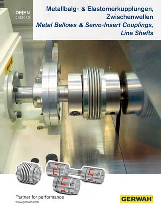
  • 1. Partner for performance www.gerwah.com DE|EN 03|2013 Metallbalg- & Elastomerkupplungen, Zwischenwellen Metal Bellows & Servo-Insert Couplings, Line Shafts
  • 2. Wir sind für Sie da A Global Presence For You Die heutige RINGFEDER POWER TRANS­MISSION GMBH wurde 1922 in Krefeld / Deutschland als Patentverwertungsgesellschaft für Reibungsfedern gegründet. Heute sind wir ein weltweiter An- bieter für Spitzenprodukte der Antriebs- und Dämpfungstechnik. Innovatives Denken in die Grenzbereiche des Möglichen zeichnet uns aus und hilft uns, mit progressiven und günstigen Lösungen den technischen Fortschritt unserer Kunden zu unterstützen. The RINGFEDER POWER TRANSMISSION GMBH was founded in 1922 in Krefeld, Germany to fabricate and promote Friction Spring technology. Today we have expanded our offerings to top power transmission and damping products. Innovative thinking sets us apart and allows us to develop progressive and economical solu- tions to support our customers. 2
  • 3. Besondere Anforderungen erfordern besondere Anstrengungen Wir stehen Ihnen mit langjähriger Erfahrung und produktivem En- gineering zur Verfügung - ob mit Standardprodukten oder auf indi- viduelle Anfrage. Wir verste­hen Dinge wie außer­­gewöhnlich hohe Belastbarkeit oder Montage-, Demontagefreund­lichkeit von Bauteilen, aber auch die Senkung von Fertigungskosten als „Dienst am Kunden“ und entwickeln effiziente und technisch ausgereifte Lösungen. Special applications require special solutions Our extensive range of RINGFEDER POWER TRANSMISSION pro- ducts can be applied to solve most applications. We don´t just sell, but by understanding the individual requirements of our customers (e.g. loads on the components, easy installation/removal capability and reduction of production costs) assist you in every step with innovative engineering to plan efficient and technically mature solutions. 3
  • 4. Übersicht · Overview Metallbalgkupplungen Metal Bellows Couplings Elastomerkupplungen Servo-Insert Couplings Zwischenwellen Line Shafts 4
  • 5. Inhalt · Content 02 Imageseiten Pages Corporate Image 04 Übersicht · Overview 05 Inhalt · Content Metallbalgkupplungen Metal Bellows Couplings 06 Grundlagen · Basics 08 Produktübersicht · Product Overview 10 Baureihe/Series EKN 12 Baureihe/Series DKN 14 Baureihe/Series DKN/S 16 Baureihe/Series PKN 18 Baureihe/Series AKN 20 Baureihe/Series AKN-H 22 Baureihe/Series AKD 24 Baureihe/Series AKD-H 26 Baureihe/Series AK 28 Baureihe/Series CKN 30 Technische Hinweise · Technical Information 35 Vorabinfo · Preview: ICL & SMC Elastomerkupplungen Servo-Insert Couplings 36 Grundlagen · Basics 39 Produktübersicht · Product Overview 40 Baureihe/Series GWE 5102 42 Baureihe/Series GWE 5103 44 Baureihe/Series GWE 5103.1 46 Baureihe/Series GWE 5107 48 Baureihe/Series GWE 5104 50 Baureihe/Series GWE 5106 52 Baureihe/Series GWE 5112 54 Technische Hinweise · Technical Information Zwischenwellen · Line Shafts 56 Grundlagen · Basics 59 Produktübersicht · Product Overview 60 Baureihe/Series GWZ 5104.1 62 Baureihe/Series GWZ 5106.1 64 Baureihe/Series AKN-ZW 66 Baureihe/Series AKN/H-ZW Montageanleitungen Mounting Instructions 68 Metallbalgkupplungen Metal Bellows Couplings 70 Elastomerkupplungen Servo-Insert Couplings 74 Zwischenwellen · Line Shafts Faxanfrage · Fax Inquiry 76 Faxanfrage Kupplungen Fax Inquiry Couplings 77 Faxanfrage Zwischenwellen Fax Inquiry Line Shafts 79 Lieferprogramm · Delivery Program RINGFEDER POWER TRANSMISSION Alle technischen Daten und Hin­weise sind unverbindlich. Rechts­ansprüche können daraus nicht abgeleitet werden. Der Anwender ist grundsätzlich verpflichtet zu prüfen, ob die dar- gestellten Produkte seinen Anforderungen genügen. Änderungen, die dem technischen Fortschritt dienen, behalten wir uns jederzeit vor. Mit Erscheinen dieses Kataloges werden alle älteren Prospekte und Fragebögen zu den gezeigten Produkten ungültig. All technical details and information are non-binding and cannot be used as a basis for legal claims. The user is obligated to determine whether the represented products meet his requirements. We reserve the right at all times to carry out modifications in the interests of technical progress. Upon the issue of this catalogue all previous brochures and questionnaires on the products displayed are no longer valid. CAD - Daten erhältlich / CAD data available: www.ringfeder.com 5
  • 6. Metallbalgkupplungen Grundlagen Spielfreie Metallbalgkupplungen Characteristics of Metal Bellows Couplings: Backlash-free transmission of torque High torsional stiffness, precision of transmission of rotational angle Different torsional stiffness Compact design, low moment of inertia Metal bellows made of stainless steel Simple and safe assembly Compensation of radial, axial and angular misalignment Free of wear, maintenance-free, no downtimes Not sensitive to temperatures between -30°C and + 100°C, Nominal torques between 0,1 – 5000 Nm Typische Eigenschaften von Metallbalgkupplungen: Spielfreie Drehmomentübertragung Hohe Verdrehsteife, exakte Übertragung des Drehwinkels Unterschiedliche Drehfedersteifen Kleine Baumaße, geringes Trägheitsmoment Metallbalg aus rostfreiem Edelstahl Einfache und betriebssichere Montage Ausgleich von radialem, axialem und winkligem Wellenversatz Kein Verschleiß, wartungsfrei, keine Stillstandzeiten Temperatur unempfindlich von -30°C bis +100°C Nenndrehmomente von 0,1 – 5000 Nm Vorteile 100% Kontrolle und Nachverfolgbarkeit durch individuelle Kennzeichnung Höhere Drehmomente bei gleicher Baugröße Kompaktere Bauweise Vergrößerte Bohrungsbereiche Kundenspezische Lösungen Höhere Sicherheit in der Anwendung, z.B. keine falschen Schraubenanzugsmomente Advantages 100% inspection and traceability through individual marking Higher torques at same dimensions Compact design Extended bore ranges Customer-specific solutions Higher safety in application, e.g. no wrong screw tightening torques Premium- Metallbalgkupplungen mit 20% höherem Drehmoment! Premium Metal Bellows Couplings with 20% higher torques! 6
  • 7. Metal Bellows Couplings Basics Spielfreie Metallbalgkupplungen werden im Maschinenbau einge- setzt wo ein Drehmoment oder eine Drehbewegung mit möglichst großer Winkelgenauigkeit von Welle zu Welle übertragen werden muss. Backlash-free Metal Bellows Couplings are used in the sector of mechanical engineering, where a torque or a rotary motion has to be transmitted from shaft to shaft in highest accuracy of angle. Pumpen mit axialen und vertikalen Antrieben Hochdynamische Portalantriebe Spindelhubeinheiten Lineareinheiten Verpackungsmaschinen Werkzeugmaschinen Sondermaschinen Pumps with axial and vertical drives High dynamic portal drives Spindle lifting units Linear units Packaging machines Machine tools Special machines Backlash-free Metal Bellows Couplings 7
  • 8. Baureihe · Series EKN Miniatur Metallbalgkupplung mit radialen Gewindestiften Miniature metal bellows coupling with radial set screws Seite/Page 10 Baureihe · Series DKN Miniatur Metallbalgkupplung mit Klemmnaben Miniature metal bellows coupling with clamping hubs Seite/Page 12 Baureihe · Series DKN/S Miniatur Metallbalgkupplung mit Klemmnabe und Spreizdorn Miniature metal bellows coupling with clamping hubs and expanding clamps Seite/Page 14 Baureihe · Series AKN Metallbalgkupplung mit Klemmnaben, kurzer Baulänge und erhöhter Dreh- federsteife Metal bellows coupling with clamping hubs, short length and higher torsional stiffness Seite/Page 18 Baureihe · Series PKN Metallbalgkupplung mit Klemmnaben (steckbar) Metal bellows coupling with pluggable clamping hub Seite/Page 16 Übersicht Metallbalgkupplungen · Overview Metal Bellows Couplings Baureihe · Series AKN-H Metallbalgkupplung mit Klemmnaben, kurzer Baulänge und erhöhter Dreh- federsteife in Halbschalenbauweise Metal bellows coupling with clamping hubs, short length and higher torsional stiffness in split hub design Seite/Page 20 8
  • 9. Übersicht Metallbalgkupplungen · Overview Metal Bellows Couplings Baureihe · Series AKD Metallbalgkupplung mit Klemmnaben Metal bellows coupling with clamping hubs Seite/Page 22 Baureihe · Series AK Metallbalgkupplung mit Innenkonus Metal bellows coupling with inner conical hub Seite/Page 26 Baureihe · Series CKN Metallbalgkupplung mit Flansch-Anbau Metal bellows coupling with flange Seite/Page 28 Baureihe · Series AKD-H Metallbalgkupplung mit Klemmnaben in Halbschalenbauweise Metal bellows coupling with clamping hubs in split hub design Seite/Page 24 CAD - Daten erhältlich / CAD data available: www.ringfeder.com 9
  • 10. Spielfreie Metallbalgkupplung Backlash-free Metal Bellows Coupling Baureihe · Series EKN Abmessungen · Dimensions Trägheitsmoment und Gewicht sind mit dem größten Bohrungsdurchmesser gerechnet. Moment of inertia and weight (mass) are calculated with reference to the largest bore size. Abmessungen · Dimensions Bestellbeispiel · Ordering example: EKN Baureihe/Series Größe/Size Länge/Length Bohrungsdurchmesser/ Bore diameter d1 Bohrungsdurchmesser/ Bore diameter d2 Weitere Angaben/ Further details* EKN 20 26 6 10 * * Passfedernut · Keyway Eigenschaften Metallbalg aus rostfreiem Stahl, Naben aus Aluminium Die Wellentoleranz sollte innerhalb der Passungstoleranz “g6“ oder “h7“ liegen Die Kontaktflächen müssen öl- und fettfrei sein Ausführungen mit Passfedernut DIN 6885-1 optional Die in den Tabellen der Technischen Daten angegebenen Drehmomentwerte können nur unter der Einhaltung aller Hinweise sicher übertragen werden. Characteristics Metal bellows made of stainless steel, hubs made of aluminum The shaft tolerance should be within the fit tolerance “g6” or “h7” The contact surfaces have to be free from oil and grease Optional designs with keyway DIN 6885-1 The torque values shown in the technical data tables can only be safely transmitted, if all instructions are followed d1, d2min = Min. Bohrungsdurchmesser 1, 2/Bore diameter d1, d2min d1, d2max = Max. Bohrungsdurchmesser 1, 2/Bore diameter d1, d2max L = Gesamtlänge Kupplung mit Überhang (Schrauben o.ä.) Total length of coupling D1, D2 = Außendurchmesser Nabe 1, 2/Outer diameter of hub 1, 2 d1, d2kmin = Min. Bohrungsdurchmesser 1, 2 (mit Passfedernut) d1, d2min with feather key groove d1, d2kmax = Max. Bohrungsdurchmesser 1, 2 (mit Passfedernut) d1, d2max with feather key groove C1 = Geführte Länge in Wellenbohrung d1 Guided length in shaft boring d1 l = Abstand Klemmschraubenbohrung zu Nabenkante Distance between clamping screw hole and hub end DG1 = Gewindedurchmesser /Thread d1;d2 min-max d1k; d2k min-max Größe Ohne Passfedernut Mit Passfedernut Size Without keyway With keyway C1 D1;D2 I L mm mm mm mm mm 4 3 - 9 6 - 8 6 16 2 20/23/26 9 3 - 9 6 - 8 6 16 2 21/25/28 15 3 - 12 6 - 10 10 20 3 25/30 20 3 - 16 6 - 14 11 25 2 26/32/36 45 6 - 22 6 - 16 16 33 4 39/48 100 6 - 28 6 - 25 20 40 4 44/54 10
  • 11. DG1 ISO 4029 120° d2 d1 D2 I C1 L±2 D1 Schnittdarstellung / Sectional view Technische Daten · Technical Data T = Übertragbares Drehmoment bei angegebenen TA Transmissible torque at given TA nmax = Max. Drehzahl/Max. rotation speed ∆Ka = Maximal zulässiger Versatz axial Max. permissible axial deviation ∆Kw = Maximal zulässiger Versatz winklig Max. permissible angularly deviation ∆Kr = Maximal zulässiger Versatz radial Max. permissible radial deviation Gw = Gewicht/Weight J = Trägheitsmoment ges./Total moment of inertia CTdyn = Drehfedersteife/Dynamic torsional stiffness Cr = Radiale Federsteife/Radial spring stiffness Ca = Axiale Federsteife/Axial spring stiffness TA1 = Anzugsmoment der Spannschraube Tightened torque of clamping screw Technische Daten · Technical Data Bohrungsbereiche / Drehmomente · Bore range / Torque values Größe Size T nmax CTdyn Cr Ca ΔKa ΔKw ΔKr J Gw DG1 TA1 Nm 1/min 10³ Nm/rad N/mm mm Grad/Degree mm 10-3 Kgm2 kg mm Nm 4 0,50 15.000 0,25/0,19/0,15 128/54/26 18/13/11 0,2/0,3/0,4 1,2/2/2 0,1/0,15/0,2 2 0,005/0,006/0,007 1 x M3 0,5 9 1,10 15.000 0,5/0,38/0,3 187/82/42 36/27/22 0,2/0,3/0,4 1,2/2/2 0,1/0,15/0,2 2/2,3/2,6 0,006/0,007/0,008 1 x M3 0,5 15 1,75 15.000 0,75/0,7 139/81 23/12 0,25/0,4 1,2/2 0,1/0,15 7,5/8 0,012/0,014 2 x M4 1,5 20 2,40 15.000 1,5/1,3/1,0 147/96/46 18/14/9 0,3/0,4/0,5 1,2/2/2 0,1/0,2/0,25 14/16/17 0,016/0,018/0,020 2 x M3 1,5 45 5,50 15.000 6,5/4 444/108 47/29 0,3/0,5 1,2/2 0,1/0,2 68/73 0,048/0,052 2 x M6 3 100 12 15.000 8,1/6,7 361/193 46/34 0,4/0,5 1,2/2 0,15/0,25 200/220 0,048/0,058 2 x M6 3 Größe Size Ø3 Ø4 Ø5 Ø6 Ø7 Ø8 Ø9 Ø10 Ø11 Ø12 Ø13 Ø14 Ø15 Ø16 Ø17 Ø18 Ø20 Ø22 Ø24 Ø26 Ø28 4 0,5 0,5 0,5 0,5 0,5 0,5 0,5 --- --- --- --- --- --- --- --- --- --- --- --- --- --- 9 0,9 0,7 1,1 1,1 1,1 1,1 1,1 --- --- --- --- --- --- --- --- --- --- --- --- --- --- 15 1,75 1,75 1,75 1,75 1,75 1,75 1,75 1,75 1,75 1,75 --- --- --- --- --- --- --- --- --- --- --- 20 2,4 2,4 2,4 2,4 2,4 2,4 2,4 2,4 2,4 2,4 2,4 2,4 2,4 2,4 --- --- --- --- --- --- --- 45 --- --- --- 5,5 5,5 5,5 5,5 5,5 5,5 5,5 5,5 5,5 5,5 5,5 5,5 5,5 5,5 5,5 --- --- --- 100 --- --- --- 7,3 8,5 9,7 11 12 12 12 12 12 12 12 12 12 12 12 12 12 12 11
  • 12. Spielfreie Metallbalgkupplung Backlash-free Metal Bellows Coupling Baureihe · Series DKN Abmessungen · Dimensions Abmessungen · Dimensions Trägheitsmoment und Gewicht sind mit dem größten Bohrungsdurchmesser gerechnet. Moment of inertia and weight (mass) are calculated with reference to the largest bore size. Bestellbeispiel · Ordering example: DKN Baureihe/Series Größe/Size Länge/Length Bohrungsdurchmesser/ Bore diameter d1 Bohrungsdurchmesser/ Bore diameter d2 Weitere Angaben/ Further details* DKN 20 42 6 10 * * Passfedernut oder Edelstahl · Keyway or stainless steel Eigenschaften Metallbalg aus rostfreiem Stahl, Naben aus Aluminium Die Wellentoleranz sollte innerhalb der Passungstoleranz “g6“ oder “h7“ liegen Die Kontaktflächen müssen öl- und fettfrei sein Ausführungen mit Passfedernut DIN 6885-1 optional Sonderausführung in Edelstahl optional Die in den Tabellen der Technischen Daten angegebenen Drehmomentwerte können nur unter der Einhaltung aller Hinweise sicher übertragen werden. Characteristics Metal bellows made of stainless steel, hubs made of aluminum The shaft tolerance should be within the fit tolerance “g6” or “h7” The contact surfaces have to be free from oil and grease Optional designs with keyway DIN 6885-1 Optional special design in stainless steel The torque values shown in the technical data tables can only be safely transmitted, if all instructions are followed. d1, d2min = Min. Bohrungsdurchmesser 1, 2/Bore diameter d1, d2min d1, d2max = Max. Bohrungsdurchmesser 1, 2/Bore diameter d1, d2max L = Gesamtlänge Kupplung mit Überhang (Schrauben o.ä.) Total length of coupling D1, D2 = Außendurchmesser Nabe 1, 2/Outer diameter of hub 1, 2 H = Stör-Durchmesser/Clearance diameter d1, d2kmin = Min. Bohrungsdurchmesser 1, 2 (mit Passfedernut) d1, d2min with feather key groove d1, d2kmax = Max. Bohrungsdurchmesser 1, 2 (mit Passfedernut) d1, d2max with feather key groove C1 = Geführte Länge in Wellenbohrung d1 Guided length in shaft boring d1 l = Abstand Klemmschraubenbohrung zu Nabenkante Distance between clamping screw hole and hub end K = Abstand Wellenachse - Klemmschraubenachse Distance shaft axis - clamping screw axis DG1 = Gewindedurchmesser /Thread d1;d2 min-max d1k;d2k min-max Größe Ohne Passfedernut Mit Passfedernut Size Without keyway With keyway C1 D1;D2 H I K L mm mm mm mm mm mm 4 3 - 8 6 - 8 7 16 18 2 5 21/24/28 9 3 - 8 6 - 8 7 16 18 2 5 23/26/30 15 3 - 10 6 - 10 9 20 21 3 7 26/30 20 3 - 14 6 - 14 11 25 27 4 9 32/38/42 45 5 - 17 6 - 17 13 33 34 5 12 41/50 100 5 - 24 6 - 19 14 40 42 5 16 47/57 12
  • 13. DG1 ISO 4762 d1 d2 D2 I L±2 C1 H K D1 Schnittdarstellung / Sectional view Technische Daten · Technical Data Technische Daten · Technical Data Bohrungsbereiche / Drehmomente · Bore range / Torque values T = Übertragbares Drehmoment bei angegebenen TA Transmissible torque at given TA nmax = Max. Drehzahl/Max. rotation speed ∆Ka = Maximal zulässiger Versatz axial Max. permissible axial deviation ∆Kw = Maximal zulässiger Versatz winklig Max. permissible angularly deviation ∆Kr = Maximal zulässiger Versatz radial Max. permissible radial deviation Gw = Gewicht/Weight J = Trägheitsmoment ges./Total moment of inertia CTdyn = Drehfedersteife/Dynamic torsional stiffness Cr = Radiale Federsteife/Radial spring stiffness Ca = Axiale Federsteife/Axial spring stiffness TA1 = Anzugsmoment der Spannschraube Tightened torque of clamping screw Größe Size T nmax CTdyn Cr Ca ΔKa ΔKw ΔKr J Gw DG1 TA1 Nm 1/min 10³ Nm/rad N/mm mm Grad/Degree mm 10-3 Kgm2 kg mm Nm 4 0,40 15.000 0,25/0,19/0,15 128/54/26 18/13/11 0,2/0,3/0,4 1,2/2/2 0,1/0,15/0,2 2,6 0,005/0,006/0,007 1 x M2 0,3 9 0,90 15.000 0,5/0,38/0,3 187/82/42 36/27/22 0,2/0,3/0,4 1,2/2/2 0,1/0,15/0,2 2,6/2,9/3,2 0,006/0,007/0,008 1 x M2 0,3 15 1,50 15.000 0,75/0,7 139/81 23/12 0,25/0,4 1,2/2 0,1/0,15 11/12 0,012/0,014 1 x M2,5 0,8 20 2 15.000 1,5/1,3/1,0 147/96/46 18/14/9 0,3/0,4/0,5 1,2/2/2 0,1/0,2/0,25 25/27/28 0,020/0,022/0,024 1 x M3 1,5 45 4,50 15.000 6,5/4 444/108 47/29 0,3/0,5 1,2/2 0,1/0,2 98/103 0,058/0,062 1 x M4 3 100 10 15.000 8,1/6,7 361/193 46/34 0,4/0,5 1,2/2 0,15/0,25 231/250 0,060/0,070 1 x M4 3 Größe Size Ø3 Ø4 Ø5 Ø6 Ø7 Ø8 Ø9 Ø10 Ø11 Ø12 Ø13 Ø14 Ø15 Ø16 Ø17 Ø18 Ø19 Ø20 Ø21 Ø22 Ø24 4 0,5 0,5 0,5 0,5 0,5 0,5 --- --- --- --- --- --- --- --- --- --- --- --- --- --- --- 9 0,5 0,5 0,5 0,5 0,5 0,5 --- --- --- --- --- --- --- --- --- --- --- --- --- --- --- 15 1,5 1,75 1,75 1,75 1,75 1,75 1,75 1,75 --- --- --- --- --- --- --- --- --- --- --- --- --- 20 1,7 2,3 2,4 2,4 2,4 2,4 2,4 2,4 2,4 2,4 2,4 2,4 --- --- --- --- --- --- --- --- --- 45 --- --- 5,5 5,5 5,5 5,5 5,5 5,5 5,5 5,5 5,5 5,5 5,5 5,5 5,5 --- --- --- --- --- --- 100 --- --- 7 8 9 10,5 12 12 12 12 12 12 12 12 12 12 12 12 12 12 12 13
  • 14. Spielfreie Metallbalgkupplung Backlash-free Metal Bellows Coupling Baureihe · Series DKN/S Abmessungen · Dimensions Trägheitsmoment und Gewicht sind mit dem größten Bohrungsdurchmesser gerechnet. Moment of inertia and weight (mass) are calculated with reference to the largest bore size. Abmessungen · Dimensions Eigenschaften Metallbalg aus rostfreiem Stahl, Naben aus Aluminium Die Wellentoleranz sollte innerhalb der Passungstoleranz “g6“ oder “h7“ liegen Die Kontaktflächen müssen öl- und fettfrei sein Ausführungen mit Passfedernut DIN 6885-1 optional Sonderausführung in Edelstahl optional Für die Bohrungstoleranz empfehlen wir Passungstoleranz H7 Die in den Tabellen der Technischen Daten angegebenen Drehmomentwerte können nur unter der Einhaltung aller Hinweise sicher übertragen werden. Characteristics Metal bellows made of stainless steel, hubs made of aluminum The shaft tolerance should be within the fit tolerance “g6” or “h7” The contact surfaces have to be free from oil and grease Optional designs with keyway DIN 6885-1 Optional special design in stainless steel For the bore tolerances we recommend fit tolerance H7 The torque values shown in the technical data tables can only be safely transmitted, if all instructions are followed. Bestellbeispiel · Ordering example: DKN/S Baureihe/Series Größe/Size Länge/Length Bohrungsdurchmesser/ Bore diameter d1 Weitere Angaben/ Further details* DKN/S 20 41 6 * * Passfedernut oder Edelstahl · Keyway or stainless steel d1min = Min. Bohrungsdurchmesser 1/Bore diameter d1min d1max = Max. Bohrungsdurchmesser 1/Bore diameter d1max L = Gesamtlänge Kupplung mit Überhang (Schrauben o.ä.) Total length of coupling D1 = Außendurchmesser Nabe 1/Outer diameter of hub 1 H = Stör-Durchmesser/Clearance diameter D4 = Ø Absatz am Nabenkörpers 2 (DKN/S: D4= DornØf7) Diam. section at hub 2 (DKN/S: D4= DornØf7) L5 = Länge Spreizdorn/Expending mandrel C1 = Geführte Länge in Wellenbohrung d1 Guided length in shaft boring d1 l = Abstand Klemmschraubenbohrung zu Nabenkante Distance between clamping screw hole and hub end K = Abstand Wellenachse - Klemmschraubenachse Distance shaft axis - clamping screw axis DG1, DG2 = Gewindedurchmesser /Thread d1 min-max d1k min-max Größe Ohne Passfedernut Mit Passfedernut Size Without keyway With keyway C1 D1;D2 D4 H I K L L5 mm mm mm mm mm mm mm mm 4 3 - 8 6 - 8 7 16 8 18 2 5 29/31/35 8 9 3 - 8 6 - 8 7 16 8 18 2 5 30/33/37 8 15 3 - 10 6 - 10 9 20 10 21 3 7 37/41 12 20 3 - 14 6 - 14 11 25 10 27 4 9 41/47/51 12 45 5 - 17 6 - 17 13 33 14 34 5 12 52/61 16 100 5 - 24 6 - 24 14 40 16 42 5 16 61/71 20 14
  • 15. DG1 ISO 4762 DG2 ISO 4762 I D4 D1 C1 d1 K HL±2 L5 Schnittdarstellung / Sectional view Technische Daten · Technical Data Technische Daten · Technical Data Bohrungsbereiche / Drehmomente · Bore range / Torque values T = Übertragbares Drehmoment bei angegebenen TA Transmissible torque at given TA nmax = Max. Drehzahl/Max. rotation speed ∆Ka = Maximal zulässiger Versatz axial Max. permissible axial deviation ∆Kw = Maximal zulässiger Versatz winklig Max. permissible angularly deviation ∆Kr = Maximal zulässiger Versatz radial Max. permissible radial deviation Gw = Gewicht/Weight J = Trägheitsmoment ges./Total moment of inertia CTdyn = Drehfedersteife/Dynamic torsional stiffness Cr = Radiale Federsteife/Radial spring stiffness Ca = Axiale Federsteife/Axial spring stiffness TA1 = Anzugsmoment der Spannschraube (DG1) Tightened torque of clamping screw (DG1) TA2 = Anzugsmoment der Spannschraube (DG2) Tightened torque of clamping screw (DG2) Größe Size T nmax CTdyn Cr Ca ΔKa ΔKw ΔKr J Gw DG1 TA1 DG2 TA2 Nm 1/min 10³ Nm/rad N/mm mm Grad/Degree mm 10-3 Kgm2 kg mm Nm Nm 4 0,50 15.000 0,25/0,19/0,15 128/54/26 18/13/11 0,2/0,3/0,4 1,2/2/2 0,1/0,15/0,2 3 0,007/0,008/0,009 1 x M2 0,3 1 x M3 1,8 9 1,10 15.000 0,5/0,38/0,3 187/82/42 36/27/22 0,2/0,3/0,4 1,2/2/2 0,1/0,15/0,2 3 0,009/0,010/0,010 1 x M2 0,3 1 x M3 1,8 15 1,75 15.000 0,75/0,7 139/81 23/12 0,25/0,4 1,2/2 0,1/0,15 11/12 0,016/0,017 1 x M2,5 0,8 1 x M4 3 20 2,40 15.000 1,5/1,3/1,0 147/96/46 18/14/9 0,3/0,4/0,5 1,2/2/2 0,1/0,2/0,25 21/23/25 0,024/0,027/0,028 1 x M3 1,5 1 x M4 3 45 5,50 15.000 6,5/4 444/108 47/29 0,3/0,5 1,2/2 0,1/0,2 80/86 0,064/0,070 1 x M4 3 1 x M5 4 100 12 15.000 8,1/6,7 361/193 46/34 0,4/0,5 1,2/2 0,15/0,25 229/256 0,070/0,087 1 x M4 3 1 x M6 6 Größe Size Ø3 Ø4 Ø5 Ø6 Ø7 Ø8 Ø9 Ø10 Ø11 Ø12 Ø13 Ø14 Ø15 Ø16 Ø17 Ø18 Ø19 Ø20 Ø21 Ø22 Ø24 4 0,5 0,5 0,5 0,5 0,5 0,5 --- --- --- --- --- --- --- --- --- --- --- --- --- --- --- 9 0,5 0,5 0,5 0,5 0,5 0,5 --- --- --- --- --- --- --- --- --- --- --- --- --- --- --- 15 1,5 1,75 1,75 1,75 1,75 1,75 1,75 1,75 --- --- --- --- --- --- --- --- --- --- --- --- --- 20 1,7 2,3 2,4 2,4 2,4 2,4 2,4 2,4 2,4 2,4 2,4 2,4 --- --- --- --- --- --- --- --- --- 45 --- --- 5,5 5,5 5,5 5,5 5,5 5,5 5,5 5,5 5,5 5,5 5,5 5,5 5,5 --- --- --- --- --- --- 100 --- --- 7 8 9 10,5 12 12 12 12 12 12 12 12 12 12 12 12 12 12 12 15
  • 16. Spielfreie Metallbalgkupplung Backlash-free Metal Bellows Coupling Baureihe · Series PKN Abmessungen · Dimensions Trägheitsmoment und Gewicht sind mit dem größten Bohrungsdurchmesser gerechnet. Moment of inertia and weight (mass) are calculated with reference to the largest bore size. Abmessungen · Dimensions Bestellbeispiel · Ordering example: PKN Baureihe/Series Größe/Size Bohrungsdurchmesser/ Bore diameter d1 Bohrungsdurchmesser/ Bore diameter d2 Weitere Angaben/ Further details* PKN 150 30 35 * * Passfedernut oder Edelstahl · Keyway or stainless steel Eigenschaften Metallbalg aus rostfreiem Stahl, Naben aus Aluminium Die Wellentoleranz sollte innerhalb der Passungstoleranz “g6“ oder “h7“ liegen Die Kontaktflächen müssen öl- und fettfrei sein Ausführungen mit Passfedernut DIN 6885-1 optional Sonderausführung in Edelstahl optional Die in den Tabellen der Technischen Daten angegebenen Drehmomentwerte können nur unter der Einhaltung aller Hinweise sicher übertragen werden. Characteristics Metal bellows made of stainless steel, hubs made of aluminum The shaft tolerance should be within the fit tolerance “g6” or “h7” The contact surfaces have to be free from oil and grease Optional designs with keyway DIN 6885-1 Optional special design in stainless steel The torque values shown in the technical data tables can only be safely transmitted, if all instructions are followed. d1, d2min = Min. Bohrungsdurchmesser 1, 2/Bore diameter d1, d2min d1, d2max = Max. Bohrungsdurchmesser 1, 2/Bore diameter d1, d2max L = Gesamtlänge Kupplung mit Überhang (Schrauben o.ä.) Total length of coupling D1, D2 = Außendurchmesser Nabe 1, 2/Outer diameter of hub 1, 2 H = Stör-Durchmesser/Clearance diameter d1, d2kmin = Min. Bohrungsdurchmesser 1, 2 (mit Passfedernut) d1, d2min with feather key groove d1, d2kmax = Max. Bohrungsdurchmesser 1, 2 (mit Passfedernut) d1, d2max with feather key groove C1, C2 = Geführte Länge in Wellenbohrung d1, d2 Guided length in shaft boring d1, d2 l = Abstand Klemmschraubenbohrung zu Nabenkante Distance between clamping screw hole and hub end L6 = Grundkörperlänge ohne Aufsteckteil oder ZW Length of basic part without plug part or ZW K = Abstand Wellenachse - Klemmschraubenachse Distance shaft axis - clamping screw axis DG1 = Gewindedurchmesser /Thread d1 min-max d2 min-max d1k min-max d2k min-max Größe Ohne Passfedernut Ohne Passfedernut Mit Passfedernut Mit Passfedernut Size Without keyway Without keyway With keyway With keyway C1 C2 D1;D2 H I K L L6 mm mm mm mm mm mm 2 3 - 14 3 - 9 6 - 14 6 - 9 11 11,5 25 28 4 9 39 26 4,5 6 - 17 6 - 16 6 - 17 6 - 16 13 13 33 35 5 12 47,5 33 10 6 - 24 6 - 22 6 - 24 6 - 22 14 13 40 42 5 16 53,5 39 18 8 - 26 8 - 22 8 - 26 8 - 22 20 18,5 45 48 6 18 70,5 50 30 10 - 30 10 - 28 10 - 30 10 - 28 25 22 55 56 8 20 72 48 60 10 - 35 10 - 30 10 - 35 10 - 30 29 29 66 67 10 24 88,5 57 80 14 - 42 14 - 42 14 - 42 14 - 42 34 33 80 85 12 28 102,5 67 150 14 - 42 14 - 42 14 - 42 14 - 42 34 33 80 85 12 28 102,5 67 16
  • 17. DG1 ISO 4762 - 2 (Größe 2 - 10) - 2,5 (Größe 18-150) d1 d2 D1,D2 L I L2 C2 C1 K H Schnittdarstellung / Sectional view Technische Daten · Technical Data Technische Daten · Technical Data Bohrungsbereiche / Drehmomente · Bore range / Torque values T = Übertragbares Drehmoment bei angegebenen TA Transmissible torque at given TA nmax = Max. Drehzahl/Max. rotation speed ∆Ka = Maximal zulässiger Versatz axial Max. permissible axial deviation ∆Kw = Maximal zulässiger Versatz winklig Max. permissible angularly deviation ∆Kr = Maximal zulässiger Versatz radial Max. permissible radial deviation Gw = Gewicht/Weight J = Trägheitsmoment ges./Total moment of inertia CTdyn = Drehfedersteife/Dynamic torsional stiffness Cr = Radiale Federsteife/Radial spring stiffness Ca = Axiale Federsteife/Axial spring stiffness TA1 = Anzugsmoment der Spannschraube Tightened torque of clamping screw Größe Size T nmax CTdyn Cr Ca ΔKa ΔKw ΔKr J Gw DG1 TA1 Nm 1/min 10³ Nm/rad N/mm mm Grad/Degree mm 10-3 Kgm2 kg mm Nm 2 2,40 22.900 1,5 147 18 0,4 1,2 0,2 0,02 0,032 1 x M3 1,5 4,50 5,50 17.600 6,5 444 47 0,3 1,2 0,1 0,03 0,066 1 x M4 3 10 12 14.100 8 361 46 0,4 1,2 0,15 0,04 0,092 1 x M4 3 18 22 12.700 8 50 200 0,5 1,5 0,2 0,054 0,164 1 x M5 6 30 36 10.200 35 50 720 0,4 1 0,1 0,123 0,280 1 x M6 12 60 75 8.600 75 90 1100 0,4 1 0,1 0,325 0,494 1 x M8 30 80 95 6.800 130 80 1200 0,4 1 0,2 0,884 0,855 1 x M10 60 150 180 6.800 150 150 2000 0,4 1 0,2 0,884 0,855 1 x M10 85 Größe Size Ø3 Ø4 Ø5 Ø6 Ø8 Ø10 Ø12 Ø14 Ø15 Ø18 Ø20 Ø21 Ø24 Ø27 Ø28 Ø30 Ø32 Ø35 Ø36 Ø38 Ø41 2 1,7 2,3 2,4 2,4 2,4 --- --- --- --- --- --- --- --- --- --- --- --- --- --- --- --- 4,50 --- --- 5,5 5,5 5,5 5,5 5,5 5,5 --- --- --- --- --- --- --- --- --- --- --- --- --- 10 --- --- --- 8 11 12 12 12 12 12 12 --- --- --- --- --- --- --- --- --- --- 18 --- --- --- --- --- 18 22 22 22 22 22 22 --- --- --- --- --- --- --- --- --- 30 --- --- --- --- --- 36 36 36 36 36 36 36 36 36 --- --- --- --- --- --- --- 60 --- --- --- --- --- --- --- 75 75 75 75 75 75 75 75 --- --- --- --- --- --- 80 --- --- --- --- --- --- --- 95 95 95 95 95 95 95 95 95 95 95 95 95 95 150 --- --- --- --- --- --- --- 180 180 180 180 180 180 180 180 180 180 180 180 180 180 17
  • 18. Spielfreie Metallbalgkupplung Backlash-free Metal Bellows Coupling Baureihe · Series AKN Abmessungen · Dimensions Trägheitsmoment und Gewicht sind mit dem größten Bohrungsdurchmesser gerechnet. Moment of inertia and weight (mass) are calculated with reference to the largest bore size. Abmessungen · Dimensions Bestellbeispiel · Ordering example: AKN Baureihe/Series Größe/Size Bohrungsdurchmesser/ Bore diameter d1 Bohrungsdurchmesser/ Bore diameter d2 Weitere Angaben/ Further details* AKN 150 30 35 * * Passfedernut oder Edelstahl · Keyway or stainless steel Eigenschaften Metallbalg aus rostfreiem Stahl, Naben aus Aluminium Die Wellentoleranz sollte innerhalb der Passungstoleranz “g6“ oder “h7“ liegen Die Kontaktflächen müssen öl- und fettfrei sein Ausführungen mit Passfedernut DIN 6885-1 optional Sonderausführung in Edelstahl optional Die in den Tabellen der Technischen Daten angegebenen Drehmomentwerte können nur unter der Einhaltung aller Hinweise sicher übertragen werden. Characteristics Metal bellows made of stainless steel, hubs made of aluminum The shaft tolerance should be within the fit tolerance “g6” or “h7” The contact surfaces have to be free from oil and grease Optional designs with keyway DIN 6885-1 Optional special design in stainless steel The torque values shown in the technical data tables can only be safely transmitted, if all instructions are followed. d1, d2min = Min. Bohrungsdurchmesser 1, 2/Bore diameter d1, d2min d1, d2max = Max. Bohrungsdurchmesser 1, 2/Bore diameter d1, d2max L = Gesamtlänge Kupplung mit Überhang (Schrauben o.ä.) Total length of coupling D1, D2 = Außendurchmesser Nabe 1, 2/Outer diameter of hub 1, 2 H = Stör-Durchmesser/Clearance diameter C1 = Geführte Länge in Wellenbohrung d1 Guided length in shaft boring d1 l = Abstand Klemmschraubenbohrung zu Nabenkante Distance between clamping screw hole and hub end K = Abstand Wellenachse - Klemmschraubenachse Distance shaft axis - clamping screw axis DG1 = Gewindedurchmesser /Thread Größe d1;d2 min.-max.Size C1 D1;D2 H I K L mm mm mm mm mm mm 18 8 - 26 20 45 48 6 18 63 30 10 - 30 25 55 56 8 20 65 60 12 - 35 29 64 67 10 24 78 80 14 - 42 33 80 84 12 28 90 150 14 - 42 33 80 84 12 28 90 200 22 - 46 38 90 93 13 31 99 300 24 - 60 38 110 110 13 39 104 500 35 - 64 41 119 122 15 43 111 18
  • 19. DG1 ISO 4762 d1 d2 D2 I L±2 K H C1 D1 Schnittdarstellung / Sectional view Technische Daten · Technical Data Technische Daten · Technical Data Bohrungsbereiche / Drehmomente · Bore range / Torque values T = Übertragbares Drehmoment bei angegebenen TA Transmissible torque at given TA nmax = Max. Drehzahl/Max. rotation speed ∆Ka = Maximal zulässiger Versatz axial Max. permissible axial deviation ∆Kw = Maximal zulässiger Versatz winklig Max. permissible angularly deviation ∆Kr = Maximal zulässiger Versatz radial Max. permissible radial deviation Gw = Gewicht/Weight J = Trägheitsmoment ges./Total moment of inertia CTdyn = Drehfedersteife/Dynamic torsional stiffness Cr = Radiale Federsteife/Radial spring stiffness Ca = Axiale Federsteife/Axial spring stiffness TA1 = Anzugsmoment der Spannschraube Tightened torque of clamping screw Größe Size T nmax CTdyn Cr Ca ΔKa ΔKw ΔKr J Gw DG1 TA1 Nm 1/min 10³ Nm/rad N/mm mm Grad/Degree mm 10-3 Kgm2 kg mm Nm 18 22 12.700 8 200 50 0,5 1,5 0,2 0,05 0,133 1 x M5 6 30 36 10.200 35 720 50 0,4 1 0,1 0,11 0,245 1 x M6 12 60 75 8.600 75 1100 90 0,4 1 0,1 0,29 0,406 1 x M8 30 80 95 6.800 130 1200 80 0,4 1 0,2 0,87 0,742 1 x M10 60 150 180 6.800 150 2000 150 0,4 1 0,2 0,87 0,742 1 x M10 85 200 240 6.300 170 2500 150 0,4 1 0,2 1,44 1,054 1 x M12 100 300 360 5.900 500 6300 280 0,4 1 0,2 3 1,434 1 x M12 120 500 600 4.900 680 8800 100 0,5 1 0,2 4,7 1,949 1 x M14 190 Größe Size Ø8 Ø9 Ø10 Ø11 Ø12 Ø13 Ø15 Ø16 Ø18 Ø20 Ø22 Ø25 Ø28 Ø30 Ø35 Ø40 Ø45 Ø50 Ø55 Ø60 Ø64 18 18 20 22 22 22 22 22 22 22 22 22 22 --- --- --- --- --- --- --- --- --- 30 --- --- 36 36 36 36 36 36 36 36 36 36 36 36 --- --- --- --- --- --- --- 60 --- --- --- --- 75 75 75 75 75 75 75 75 75 75 75 --- --- --- --- --- --- 80 --- --- --- --- --- --- ,95 95 95 95 95 95 95 95 95 95 --- --- --- --- --- 150 --- --- --- --- --- --- 180 180 180 180 180 180 180 180 180 180 --- --- --- --- --- 200 --- --- --- --- --- --- --- --- --- --- 240 240 240 240 240 240 240 --- --- --- --- 300 --- --- --- --- --- --- --- --- --- --- --- 360 360 360 360 360 360 360 360 360 --- 500 --- --- --- --- --- --- --- --- --- --- --- --- --- --- 600 600 600 600 600 600 600 19
  • 20. Spielfreie Metallbalgkupplung Backlash-free Metal Bellows Coupling Baureihe · Series AKN-H Abmessungen · Dimensions Trägheitsmoment und Gewicht sind mit dem größten Bohrungsdurchmesser gerechnet. Moment of inertia and weight (mass) are calculated with reference to the largest bore size. Abmessungen · Dimensions Bestellbeispiel · Ordering example: AKN-H Baureihe/Series Größe/Size Bohrungsdurchmesser/ Bore diameter d1 Bohrungsdurchmesser/ Bore diameter d2 Weitere Angaben/ Further details* AKN-H 150 32 42 * * Passfedernut oder Edelstahl · Keyway or stainless steel Eigenschaften Metallbalg aus rostfreiem Stahl, Naben aus Aluminium Die Wellentoleranz sollte innerhalb der Passungstoleranz “g6“ oder “h7“ liegen Die Kontaktflächen müssen öl- und fettfrei sein Ausführungen mit Passfedernut DIN 6885-1 optional Sonderausführung in Edelstahl optional Die in den Tabellen der Technischen Daten angegebenen Drehmomentwerte können nur unter der Einhaltung aller Hinweise sicher übertragen werden. Characteristics Metal bellows made of stainless steel, hubs made of aluminum The shaft tolerance should be within the fit tolerance “g6” or “h7” The contact surfaces have to be free from oil and grease Optional designs with keyway DIN 6885-1 Optional special design in stainless steel The torque values shown in the technical data tables can only be safely transmitted, if all instructions are followed. d1, d2min = Min. Bohrungsdurchmesser 1, 2/Bore diameter d1, d2min d1, d2max = Max. Bohrungsdurchmesser 1, 2/Bore diameter d1, d2max L = Gesamtlänge Kupplung mit Überhang (Schrauben o.ä.) Total length of coupling D1, D2 = Außendurchmesser Nabe 1, 2/Outer diameter of hub 1, 2 H = Stör-Durchmesser/Clearance diameter K1, K2 = Klemmlänge von d1, d2/Clamping length of d1, d2 C1 = Geführte Länge in Wellenbohrung d1 Guided length in shaft boring d1 l = Abstand Klemmschraubenbohrung zu Nabenkante Distance between clamping screw hole and hub end K = Abstand Wellenachse - Klemmschraubenachse Distance shaft axis - clamping screw axis DG1 = Gewindedurchmesser /Thread Größe d1;d2 min.-max.Size C1 D1;D2 H I K K1 L mm mm mm mm mm mm 18 8 - 26 20 45 48 6 18 11 63 30 10 - 30 25 55 56 8 20 15 65 60 12 - 35 29 64 67 10 24 19 78 80 14 - 42 33 80 84 12 28 21 90 150 14 - 42 33 80 84 12 28 21 90 200 22 - 46 38 90 93 13 31 24 99 300 24 - 60 38 110 110 13 39 24 104 500 35 - 64 41 119 122 15 43 27,5 111 20
  • 21. DG1 ISO 4762 d1 d2 L±2 I H K D2 C1 K1 D1 Schnittdarstellung / Sectional view Technische Daten · Technical Data Technische Daten · Technical Data Bohrungsbereiche / Drehmomente · Bore range / Torque values T = Übertragbares Drehmoment bei angegebenen TA Transmissible torque at given TA nmax = Max. Drehzahl/Max. rotation speed ∆Ka = Maximal zulässiger Versatz axial Max. permissible axial deviation ∆Kw = Maximal zulässiger Versatz winklig Max. permissible angularly deviation ∆Kr = Maximal zulässiger Versatz radial Max. permissible radial deviation Gw = Gewicht/Weight J = Trägheitsmoment ges./Total moment of inertia CTdyn = Drehfedersteife/Dynamic torsional stiffness Cr = Radiale Federsteife/Radial spring stiffness Ca = Axiale Federsteife/Axial spring stiffness TA1 = Anzugsmoment der Spannschraube Tightened torque of clamping screw Größe Size T nmax CTdyn Cr Ca ΔKa ΔKw ΔKr J Gw DG1 TA1 Nm 1/min 10³ Nm/rad N/mm mm Grad/Degree mm 10-3 Kgm2 kg mm Nm 18 22 12.700 8 200 50 0,5 1,5 0,2 0,05 0,15 2 x M5 6 30 36 10.200 35 720 50 0,4 1 0,1 0,11 0,25 2 x M6 12 60 75 8.600 75 1100 90 0,4 1 0,1 0,29 0,42 2 x M8 30 80 95 6.800 130 1200 80 0,4 1 0,2 0,87 0,77 2 x M10 60 150 180 6.800 150 2000 150 0,4 1 0,2 0,87 0,77 2 x M10 85 200 240 6.300 170 2500 150 0,4 1 0,2 1,44 1,11 2 x M12 100 300 360 5.900 500 6300 280 0,4 1 0,2 3 1,5 2 x M12 120 500 600 4.900 680 8800 100 0,5 1 0,2 4,7 2 2 x M14 190 Größe Size Ø8 Ø9 Ø10 Ø11 Ø12 Ø14 Ø15 Ø18 Ø20 Ø22 Ø24 Ø25 Ø28 Ø30 Ø35 Ø40 Ø45 Ø50 Ø55 Ø60 Ø64 18 13,6 15,3 17 18,7 20,4 22 22 22 22 22 22 22 --- --- --- --- --- --- --- --- --- 30 --- --- 28 30 33 36 36 36 36 36 36 36 36 36 --- --- --- --- --- --- --- 60 --- --- --- --- 62 73 75 75 75 75 75 75 75 75 75 --- --- --- --- --- --- 80 --- --- --- --- --- 95 95 95 95 95 95 95 95 95 95 95 --- --- --- --- --- 150 --- --- --- --- --- 167 180 180 180 180 180 180 180 180 180 180 --- --- --- --- --- 200 --- --- --- --- --- --- --- --- --- 240 240 240 240 240 240 240 240 --- --- --- --- 300 --- --- --- --- --- --- --- --- --- --- 342 360 360 360 360 360 360 360 360 360 --- 500 --- --- --- --- --- --- --- --- --- --- --- --- --- --- 600 600 600 600 600 600 600 21
  • 22. Spielfreie Metallbalgkupplung Backlash-free Metal Bellows Coupling Baureihe · Series AKD Abmessungen · Dimensions Trägheitsmoment und Gewicht sind mit dem größten Bohrungsdurchmesser gerechnet. Moment of inertia and weight (mass) are calculated with reference to the largest bore size. Abmessungen · Dimensions Bestellbeispiel · Ordering example: AKD Baureihe/Series Größe/Size Bohrungsdurchmesser/ Bore diameter d1 Bohrungsdurchmesser/ Bore diameter d2 Weitere Angaben/ Further details* AKD 150 30 35 * * Passfedernut oder Edelstahl · Keyway or stainless steel Eigenschaften Metallbalg aus rostfreiem Stahl, Naben aus Aluminium/ Naben ab Größe 800 aus Stahl Die Wellentoleranz sollte innerhalb der Passungstoleranz “g6“ oder “h7“ liegen Die Kontaktflächen müssen öl- und fettfrei sein Ausführungen mit Passfedernut DIN 6885-1 optional Sonderausführung in Edelstahl optional Weitere Größen auf Anfrage Characteristics Metal bellows made of stainless steel, hubs made of aluminum/ hubs from size 800 made of steel The shaft tolerance should be within the fit tolerance “g6” or “h7” The contact surfaces have to be free from oil and grease Optional designs with keyway DIN 6885-1 Optional special design in stainless steel Other sizes available on request Die in den Tabellen der Technischen Daten angegebenen Dreh- momentwerte können nur unter der Einhaltung aller Hinweise sicher übertragen werden. The torque values shown in the technical data tables can only be safely transmitted, if all instructions are followed. d1, d2min = Min. Bohrungsdurchmesser 1, 2/Bore diameter d1, d2min d1, d2max = Max. Bohrungsdurchmesser 1, 2/Bore diameter d1, d2max L = Gesamtlänge Kupplung mit Überhang (Schrauben o.ä.) Total length of coupling D1, D2 = Außendurchmesser Nabe 1, 2/Outer diameter of hub 1, 2 H = Stör-Durchmesser/Clearance diameter C1 = Geführte Länge in Wellenbohrung d1 Guided length in shaft boring d1 l = Abstand Klemmschraubenbohrung zu Nabenkante Distance between clamping screw hole and hub end K = Abstand Wellenachse - Klemmschraubenachse Distance shaft axis - clamping screw axis DG1 = Gewindedurchmesser /Thread Größe d1;d2 min.-max.Size C1 D1;D2 H I K L mm mm mm mm mm mm 18 8 - 26 20 45 47 6 18 71 30 10 - 30 25 55 56 8 20 73 60 12 - 35 29 64 67 10 24 89 80 14 - 42 34 80 84 12 28 103 150 14 - 42 34 80 84 12 28 103 200 22 - 46 38 90 93 13 31 113 300 24 - 60 38 110 110 13 39 115 500 35 - 64 41 119 122 15 43 122 800 40 - 75 45 132 139 17 48 140 22
  • 23. DG1 ISO 4762 d1 d2 D2 L±2 K H I C1 D1 Schnittdarstellung / Sectional view Technische Daten · Technical Data Technische Daten · Technical Data Bohrungsbereiche / Drehmomente · Bore range / Torque values T = Übertragbares Drehmoment bei angegebenen TA Transmissible torque at given TA nmax = Max. Drehzahl/Max. rotation speed ∆Ka = Maximal zulässiger Versatz axial Max. permissible axial deviation ∆Kw = Maximal zulässiger Versatz winklig Max. permissible angularly deviation ∆Kr = Maximal zulässiger Versatz radial Max. permissible radial deviation Gw = Gewicht/Weight J = Trägheitsmoment ges./Total moment of inertia CTdyn = Drehfedersteife/Dynamic torsional stiffness Cr = Radiale Federsteife/Radial spring stiffness Ca = Axiale Federsteife/Axial spring stiffness TA1 = Anzugsmoment der Spannschraube Tightened torque of clamping screw Größe Size T nmax CTdyn Cr Ca ΔKa ΔKw ΔKr J Gw DG1 TA1 Nm 1/min 10³ Nm/rad N/mm mm Grad/Degree mm 10-3 Kgm2 kg mm Nm 18 22 12.700 6 85 40 0,5 1,5 0,2 0,06 0,143 1 x M5 6 30 36 10.200 25 220 30 0,5 1,5 0,2 0,1 0,263 1 x M6 12 60 75 8.600 50 330 55 0,5 1,5 0,2 0,3 0,434 1 x M8 30 80 95 6.800 75 400 55 0,5 1,5 0,2 0,9 0,792 1 x M10 60 150 180 6.800 100 600 85 0,5 1,5 0,2 0,9 0,792 1 x M10 85 200 240 6.300 120 450 85 0,5 1,5 0,2 1,5 1,117 1 x M12 100 300 360 5.900 280 1500 150 0,5 1,5 0,2 3,2 1,495 1 x M12 120 500 600 4.900 310 1000 85 1 1,5 0,2 4,9 2,038 1 x M14 190 800 800 5.000 780 6200 100 3,5 1,5 0,35 17,5 6,06 2 x M16 250 Größe Size Ø8 Ø9 Ø10 Ø11 Ø12 Ø14 Ø15 Ø16 Ø18 Ø20 Ø25 Ø30 Ø35 Ø40 Ø45 Ø50 Ø55 Ø60 Ø65 Ø70 Ø75 18 18 20 22 22 22 22 22 22 22 22 22 --- --- --- --- --- --- --- --- --- --- 30 --- --- 36 36 36 36 36 36 36 36 36 36 --- --- --- --- --- --- --- --- --- 60 --- --- --- --- 75 75 75 75 75 75 75 75 75 --- --- --- --- --- --- --- --- 80 --- --- --- --- --- --- 95 95 95 95 95 95 95 95 --- --- --- --- --- --- --- 150 --- --- --- --- --- --- 180 180 180 180 180 180 180 180 --- --- --- --- --- --- --- 200 --- --- --- --- --- --- --- --- --- --- 240 240 240 240 240 --- --- --- --- --- --- 300 --- --- --- --- --- --- --- --- --- --- 360 360 360 360 360 360 360 360 --- --- --- 500 --- --- --- --- --- --- --- --- --- --- --- --- 600 600 600 600 600 600 600 --- --- 800 --- --- --- --- --- --- --- --- --- --- --- --- --- 800 800 800 800 800 800 800 800 23
  • 24. Spielfreie Metallbalgkupplung Backlash-free Metal Bellows Coupling Baureihe · Series AKD-H Abmessungen · Dimensions Trägheitsmoment und Gewicht sind mit dem größten Bohrungsdurchmesser gerechnet. Moment of inertia and weight (mass) are calculated with reference to the largest bore size. Abmessungen · Dimensions Bestellbeispiel · Ordering example: AKD-H Baureihe/Series Größe/Size Bohrungsdurchmesser/ Bore diameter d1 Bohrungsdurchmesser/ Bore diameter d2 Weitere Angaben/ Further details* AKD-H 150 30 35 * * Passfedernut oder Edelstahl · Keyway or stainless steel Eigenschaften Metallbalg aus rostfreiem Stahl, Naben aus Aluminium/ Naben ab Größe 800 aus Stahl Die Wellentoleranz sollte innerhalb der Passungstoleranz “g6“ oder “h7“ liegen Die Kontaktflächen müssen öl- und fettfrei sein Ausführungen mit Passfedernut DIN 6885-1 optional Sonderausführung in Edelstahl optional Weitere Größen auf Anfrage Characteristics Metal bellows made of stainless steel, hubs made of aluminum/ hubs from size 800 made of steel The shaft tolerance should be within the fit tolerance “g6” or “h7” The contact surfaces have to be free from oil and grease Optional designs with keyway DIN 6885-1 Optional special design in stainless steel Other sizes available on request Die in den Tabellen der Technischen Daten angegebenen Dreh- momentwerte können nur unter der Einhaltung aller Hinweise sicher übertragen werden. The torque values shown in the technical data tables can only be safely transmitted, if all instructions are followed. d1, d2min = Min. Bohrungsdurchmesser 1, 2/Bore diameter d1, d2min d1, d2max = Max. Bohrungsdurchmesser 1, 2/Bore diameter d1, d2max L = Gesamtlänge Kupplung mit Überhang (Schrauben o.ä.) Total length of coupling D1, D2 = Außendurchmesser Nabe 1, 2/Outer diameter of hub 1, 2 H = Stör-Durchmesser/Clearance diameter K1 = Klemmlänge von d1/Clamping length of d1 C1 = Geführte Länge in Wellenbohrung d1 Guided length in shaft boring d1 l = Abstand Klemmschraubenbohrung zu Nabenkante Distance between clamping screw hole and hub end K = Abstand Wellenachse - Klemmschraubenachse Distance shaft axis - clamping screw axis DG1 = Gewindedurchmesser /Thread Größe d1;d2 min.-max.Size C1 D1;D2 H I K K1 L mm mm mm mm mm mm 18 8 - 26 20 45 47 6 18 11 71 30 10 - 30 25 55 56 8 20 15 73 60 12 - 35 29 64 67 10 24 19 89 80 14 - 42 34 80 84 12 28 21 103 150 14 - 42 34 80 84 12 28 21 103 200 22 - 46 38 90 93 13 31 24 113 300 24 - 60 38 110 110 13 39 24 115 500 35 - 64 41 119 122 15 43 27,5 122 800 40 - 75 45 132 139 17 48 34 140 24
  • 25. DG1 ISO 4762 d1 d2 L±2 I H K D2 C1 K1 D1 Schnittdarstellung / Sectional view Technische Daten · Technical Data Technische Daten · Technical Data Bohrungsbereiche / Drehmomente · Bore range / Torque values T = Übertragbares Drehmoment bei angegebenen TA Transmissible torque at given TA nmax = Max. Drehzahl/Max. rotation speed ∆Ka = Maximal zulässiger Versatz axial Max. permissible axial deviation ∆Kw = Maximal zulässiger Versatz winklig Max. permissible angularly deviation ∆Kr = Maximal zulässiger Versatz radial Max. permissible radial deviation Gw = Gewicht/Weight J = Trägheitsmoment ges./Total moment of inertia CTdyn = Drehfedersteife/Dynamic torsional stiffness Cr = Radiale Federsteife/Radial spring stiffness Ca = Axiale Federsteife/Axial spring stiffness TA1 = Anzugsmoment der Spannschraube Tightened torque of clamping screw Größe Size T nmax CTdyn Cr Ca ΔKa ΔKw ΔKr J Gw DG1 TA1 Nm 1/min 10³ Nm/rad N/mm mm Grad/Degree mm 10-3 Kgm2 kg mm Nm 18 22 12.700 6 85 40 0,5 1,5 0,2 0,06 0,16 2 x M5 6 30 36 10.200 25 220 30 0,5 1,5 0,2 0,1 0,268 2 x M6 12 60 75 8.600 50 330 55 0,5 1,5 0,2 0,3 0,448 2 x M8 30 80 95 6.800 75 400 55 0,5 1,5 0,2 0,9 0,82 2 x M10 60 150 180 6.800 100 600 85 0,5 1,5 0,2 0,9 0,82 2 x M10 85 200 240 6.300 120 450 85 0,5 1,5 0,2 1,5 1,173 2 x M12 100 300 360 5.900 280 1500 150 0,5 1,5 0,2 3,2 1,561 2 x M12 120 500 600 4.900 310 1000 85 1 1,5 0,2 4,9 2,089 2 x M14 190 800 800 5.000 780 6200 100 3,5 1,5 0,35 17,5 6,06 2 x M16 250 Größe Size Ø8 Ø9 Ø10 Ø11 Ø12 Ø14 Ø15 Ø18 Ø20 Ø24 Ø25 Ø30 Ø35 Ø40 Ø45 Ø50 Ø55 Ø60 Ø65 Ø70 Ø75 18 14 15 17 19 20 22 22 22 22 22 22 --- --- --- --- --- --- --- --- --- --- 30 --- --- 28 30 33 36 36 36 36 36 36 36 --- --- --- --- --- --- --- --- --- 60 --- --- --- --- 62 73 75 75 75 75 75 75 75 --- --- --- --- --- --- --- --- 80 --- --- --- --- --- 95 95 95 95 95 95 95 95 95 --- --- --- --- --- --- --- 150 --- --- --- --- --- 167 180 180 180 180 180 180 180 180 --- --- --- --- --- --- --- 200 --- --- --- --- --- --- --- --- --- 240 240 240 240 240 240 --- --- --- --- --- --- 300 --- --- --- --- --- --- --- --- --- 342 360 360 360 360 360 360 360 360 --- --- --- 500 --- --- --- --- --- --- --- --- --- --- --- --- 600 600 600 600 600 600 600 --- --- 800 --- --- --- --- --- --- --- --- --- --- --- --- --- 800 800 800 800 800 800 800 800 25
  • 26. Spielfreie Metallbalgkupplung Backlash-free Metal Bellows Coupling Baureihe · Series AK Abmessungen · Dimensions Abmessungen · Dimensions Trägheitsmoment und Gewicht sind mit dem größten Bohrungsdurchmesser gerechnet. Moment of inertia and weight (mass) are calculated with reference to the largest bore size. Bestellbeispiel · Ordering example: AK Baureihe/Series Größe/Size Länge/Length Bohrungsdurchmesser/ Bore diameter d1 Bohrungsdurchmesser/ Bore diameter d2 Weitere Angaben/ Further details* AK 150 79 30 35 * * Edelstahl · Stainless steel Eigenschaften Metallbalg aus rostfreiem Stahl, Konusbuchsen aus Stahl Naben bis Größe 500 aus Aluminium, Größe 800 – 5000 Naben aus Stahl Die Wellentoleranz sollte innerhalb der Passungstoleranz “g6“ oder “h7“ liegen Die Kontaktflächen müssen öl- und fettfrei sein Sonderausführung in Edelstahl optional Die in den Tabellen der Technischen Daten angegebenen Drehmomentwerte können nur unter der Einhaltung aller Hinweise sicher übertragen werden. Characteristics Metal bellows made of stainless steel, conical bushings made of steel Hubs up to size 500 made of aluminum, sizes 800 – 5000 hubs made of steel The shaft tolerance should be within the fit tolerance “g6” or “h7” The contact surfaces have to be free from oil and grease Optional special design in stainless steel The torque values shown in the technical data tables can only be safely transmitted, if all instructions are followed. d1, d2min = Min. Bohrungsdurchmesser 1, 2/Bore diameter d1, d2min d1, d2max = Max. Bohrungsdurchmesser 1, 2/Bore diameter d1, d2max L = Gesamtlänge Kupplung mit Überhang (Schrauben o.ä.) Total length of coupling D1, D2 = Außendurchmesser Nabe 1, 2/Outer diameter of hub 1, 2 B = Außendurchmesser Balg/Bellow outer diameter C = Durchmesser Lochkreis/Pitch circle L1 = Kupplungslänge/Length of coupling L4 = Länge Kupplungskörper (ohne Konus/Klemmring) Length of coupling piece (without cone/clamping ring) DG1 = Gewindedurchmesser /Thread Größe d1;d2 min.-max.Size B C D1;D2 L L1 L4 mm mm mm mm mm 30 9 - 20 56 31 55 52/60 45/53 30/38 60 12 - 25 66 37 64 63/73 55/65 35/46 80 15 - 35 82 51 80 79/91 72/83 49/61 150 15 - 35 82 51 80 79/91 72/84 49/61 200 15 - 42 90 51/56 90 80/93 72/85 50/63 300 15 - 50 110 62/75 110 93/104 80/93 56/67 500 24 - 55 122 75/80 119 102/113 94/105 61/72 800 30 - 70 157 92/100 140 170 150 110 1.400 35 - 70 157 92/100 140 170 150 110 3.000 50 - 80 199 100/115 180 191 176 136 5.000 60 - 90 250 100/125 230 199 179 139 26
  • 27. DG1 ISO 4017 d1 C B d2 D2 L4 L1 L±2 Schnittdarstellung / Sectional view Technische Daten · Technical Data Technische Daten · Technical Data Bohrungsbereiche / Drehmomente · Bore range / Torque values T = Übertragbares Drehmoment bei angegebenen TA Transmissible torque at given TA nmax = Max. Drehzahl/Max. rotation speed ∆Ka = Maximal zulässiger Versatz axial Max. permissible axial deviation ∆Kw = Maximal zulässiger Versatz winklig Max. permissible angularly deviation ∆Kr = Maximal zulässiger Versatz radial Max. permissible radial deviation Gw = Gewicht/Weight J = Trägheitsmoment ges./Total moment of inertia CTdyn = Drehfedersteife/Dynamic torsional stiffness Cr = Radiale Federsteife/Radial spring stiffness Ca = Axiale Federsteife/Axial spring stiffness TA1 = Anzugsmoment der Spannschraube Tightened torque of clamping screw Größe Size T nmax CTdyn Cr Ca ΔKa ΔKw ΔKr J Gw DG1 TA1 Nm 1/min 10³ Nm/rad N/mm mm Grad/Degree mm 10-3 Kgm2 kg mm Nm 30 36 11.000 35/25 720/220 50/30 0,4/0,5 1/1,5 0,1/0,2 0,15 0,281 6 x M4 3 60 72 9.100 75/50 1100/330 90/55 0,4/0,5 1/1,5 0,1/0,2 0,24 0,482 6 x M6 8,5 80 96 7.000 130/75 1200/400 80/55 0,4/0,5 1/1,5 0,2/0,2 0,65 0,846 6 x M6 10 150 180 7.000 150/100 2000/600 150/85 0,4/0,5 1/1,5 0,2/0,2 0,65 0,846 6 x M6 14 200 240 6.700 170/120 2500/450 150/85 0,4/0,5 1/1,5 0,2/0,2 0,87 1,005 6 x M6 14 300 360 5.200 500/280 6300/1500 280/150 0,4/0,5 1/1,5 0,2/0,2 2,33 1,915 6 x M8 18 500 600 4.600 680/310 8800/1000 100/85 0,5/1 1/1,5 0,2/0,2 5,73 2,448 6 x M8 26 800 800 3.700 760 510 190 1 1,5 0,2 26,1 9,978 6 x M16 50 1.400 1.400 3.700 1300 710 280 1 1,5 0,2 26,1 9,202 6 x M16 80 3.000 3.000 2.800 2800 8060 880 1 1,5 0,2 86,83 14,57 6 x M12 120 5.000 5.000 2.800 4800 9190 510 1 1,5 0,2 170,3 24,3 6 x M16 210 Größe Size Ø9 Ø10 Ø12 Ø14 Ø15 Ø18 Ø20 Ø24 Ø28 Ø32 Ø38 Ø44 Ø48 Ø50 Ø58 Ø60 Ø65 Ø70 Ø75 Ø80 Ø85 Ø90 30 36 36 36 36 36 36 36 --- --- --- --- --- --- --- --- --- --- --- --- --- --- --- 60 --- --- 72 72 72 72 72 72 --- --- --- --- --- --- --- --- --- --- --- --- --- --- 80 --- --- --- --- 96 96 96 96 96 96 --- --- --- --- --- --- --- --- --- --- --- --- 150 --- --- --- --- 180 180 180 180 180 180 --- --- --- --- --- --- --- --- --- --- --- --- 200 --- --- --- --- 240 240 240 240 240 240 240 --- --- --- --- --- --- --- --- --- --- --- 300 --- --- --- --- 290 350 360 360 360 360 360 360 360 --- --- --- --- --- --- --- --- --- 500 --- --- --- --- --- --- --- 600 600 600 600 600 600 600 --- --- --- --- --- --- --- --- 800 --- --- --- --- --- --- --- --- 800 800 800 800 800 800 800 800 800 800 --- --- --- --- 1.400 --- --- --- --- --- --- --- --- --- 1400 1400 1400 1400 1.400 1.400 1.400 1.400 1.400 --- --- --- --- 3.000 --- --- --- --- --- --- --- --- --- --- --- --- 3000 3.000 3.000 3.000 3.000 3.000 3.000 3.000 --- --- 5.000 --- --- --- --- --- --- --- --- --- --- --- --- --- --- 5.000 5.000 5.000 5.000 5.000 5.000 5.000 5.000 27
  • 28. Spielfreie Metallbalgkupplung Backlash-free Metal Bellows Coupling Baureihe · Series CKN Abmessungen · Dimensions Abmessungen · Dimensions Bestellbeispiel · Ordering example: CKN Baureihe/Series Größe/Size Länge/Length Weitere Angaben/ Further details* CKN 150 52 * * Edelstahl · Stainless steel Eigenschaften Metallbalg aus rostfreiem Stahl Naben bis Größe 500 aus Aluminium, Größe 800 – 5000 Naben aus Stahl Die Kontaktflächen müssen öl- und fettfrei sein Sonderausführung in Edelstahl optional Die in den Tabellen der Technischen Daten angegebenen Drehmomentwerte können nur unter der Einhaltung aller Hinweise sicher übertragen werden. Characteristics Metal bellows made of stainless steel Hubs up to size 500 made of aluminum, sizes 800 – 5000 hubs made of steel The contact surfaces have to be free from oil and grease Optional special design in stainless steel The torque values shown in the technical data tables can only be safely transmitted, if all instructions are followed. d1, d2min = Min. Bohrungsdurchmesser 1, 2/Bore diameter d1, d2min d1, d2max = Max. Bohrungsdurchmesser 1, 2/Bore diameter d1, d2max D1, D2 = Außendurchmesser Nabe 1, 2/Outer diameter of hub 1, 2 B = Außendurchmesser Balg/Bellow outer diameter C = Durchmesser Lochkreis/Pitch circle L1 = Kupplungslänge/Length of coupling M = Max. Einschraubtiefe/Max. depth of screw in DG1 = Gewindedurchmesser /Thread Größe Size d1; d2 B C D1;D2 L M mm mm mm mm mm 18 22 46 31 46 36/44 6 30 28 56 37 55 30/38 7 60 38 66 46 64 41/51 10 80 50 82 62 80 52/62 13 150 50 82 62 80 52/62 13 200 50 90 62 90 51/63 13 300 50 110 80 109 55/66 13 500 70 122 94 119 61/72 16 800 85 157 110 152 130 18 1.400 85 157 110 152 130 18 3.000 100 199 140 180 130 25 5.000 145 250 190 230 143 25 28
  • 29. d1 C B d2 D2 DG1 M L±2 D1 Schnittdarstellung / Sectional view Technische Daten · Technical Data Technische Daten · Technical Data Schraubenqualität ist entsprechend den Anziehmomenten zu wählen Screw quality should be selected according to the tightening torque Auflagefläche der Verschraubung trocken, öl- und fettfrei The contact surfaces have to be dry and free from oil and grease T = Übertragbares Drehmoment bei angegebenen TA Transmissible torque at given TA nmax = Max. Drehzahl/Max. rotation speed ∆Ka = Maximal zulässiger Versatz axial Max. permissible axial deviation ∆Kw = Maximal zulässiger Versatz winklig Max. permissible angularly deviation ∆Kr = Maximal zulässiger Versatz radial Max. permissible radial deviation Gw = Gewicht/Weight J = Trägheitsmoment ges./Total moment of inertia CTdyn = Drehfedersteife/Dynamic torsional stiffness Cr = Radiale Federsteife/Radial spring stiffness Ca = Axiale Federsteife/Axial spring stiffness TA1 = Anzugsmoment der Spannschraube Tightened torque of clamping screw Größe Size T nmax CTdyn Cr Ca ΔKa ΔKw ΔKr J Gw DG1 TA1 Nm 1/min 10³ Nm/rad N/mm mm Grad/Degree mm 10-3 Kgm2 kg mm Nm 18 22 13.900 8/6 200/85 50/40 0,5 1,5 0,2 0,05 0,063 6 x M5 5,9 30 36 11.000 35/25 720/220 50/30 0,4/0,5 1/1,5 0,1/0,2 0,09 0,117 6 x M5 5,9 60 75 9.000 75/50 1100/330 90/55 0,4/0,5 1/1,5 0,1/0,2 0,16 0,192 6 x M6 10 80 96 7.100 130/75 1200/400 80/55 0,4/0,5 1/1,5 0,2/0,2 0,43 0,356 6 x M6 10 150 180 7.100 150/100 2000/600 150/85 0,4/0,5 1/1,5 0,2/0,2 0,43 0,356 6 x M6 15 200 240 6.600 170/120 2500/450 150/85 0,4/0,5 1/1,5 0,2/0,2 0,8 0,477 6 x M6 18 300 360 5.200 500/280 6300/1500 280/150 0,4/0,5 1/1,5 0,2/0,2 1,7 0,591 6 x M8 25 500 600 4.600 680/310 8800/1000 100/85 0,5/1 1/1,5 0,2/0,2 2,3 0,876 6 x M8 36 800 960 3.700 760 510 190 1 1,5 0,2 11 3,737 6 x M16 210 1.400 1.680 3.700 1300 710 280 1 1,5 0,2 11 3,728 6 x M16 210 3.000 3.000 3.700 2800 2950 310 1 1,5 0,2 47 7,8 6 x M20 365 5.000 5.000 3.000 4800 4920 510 1 1,5 0,2 119 11,742 8 x M20 365 29
  • 30. Technische Hinweise · Metallbalgkupplungen Auslegung/Produktinformation Spielfreie, drehsteife Metallbalgkupplungen werden einbaufertig geliefert. Der Metallbalg ist aus rostfreiem Stahl, alle anderen Teile sind aus Aluminium, bzw. Stahl gefertigt und haben zum Teil eine umweltfreundliche Konservierung. Die Wellentoleranz sollte inner- halb der Passungstoleranz “g6“ oder “h7“ liegen. Die Kraftüber- tragung zwischen Kupplungsnabe und Welle erfolgt durch Pres- sung und Reibung zwischen den Kontaktflächen. Auf kontrollierten Anzug der Spannschrauben sowie einwandfreie Beschaffenheit der Kontaktflächen ist besonders zu achten. Die Kontaktflächen müssen öl- und fettfrei sein, bei einer Rautiefe von Rtmax. 16 µ für die Welle. Ausführungen mit Passfedernut sind möglich. Die ange- gebenen Drehmomente können nur bei Einhaltung aller Hinweise sicher übertragen werden. Sonst müssen Abstriche gemacht wer- den. Auslegung nach dem Drehmoment Metallbalgkupplungen werden meist nach dem in der Liste der technischen Daten angegebenen Nenndrehmoment TKN ausge- legt. Dabei muss das Nenndrehmoment in allen Fällen über dem regelmäßig zu übertragenden Drehmoment liegen. Dies gilt vor allem für den Einsatz an Servomotoren, deren Beschleunigungs- moment in positiver und negativer Richtung um ein Mehrfaches über dem Nenndrehmoment liegt. Für Metallbalgkupplungen, die an geregelten, hochdynamischen Antrieben eingesetzt werden, ha- ben sich folgende Dimensionierungswerte in der Praxis bewährt: K = 1,5 bei gleichförmiger Bewegung K = 2 bei ungleichförmiger Bewegung K = 2,5 – 4 bei stoßender Bewegung Für Servoantriebe an Werkzeugmaschinen sind Werte für K = 1,5 – 2 einzusetzen. Wir führen gerne für Sie die Auslegungsberechnung durch. Nutzen Sie unsere Kompetenz für Ihren Erfolg. Bitte sprechen Sie uns an! Auslegung von Metallbalgkupplungen / Berechnungsbeispiel Servomotor Schlitten Metallbalgkupplung Kugelrollspindel TKN ≥ K · TAS · JMasch JMot + JMasch = [Nm] 30
  • 31. Technical Information · Metal Bellows Couplings Design / Sample calculation Design/Product information Backlash-free, torsionally stiff metal bellows couplings are ready to install when delivered. The metal bellows are made of stainless steel, all other parts are made of aluminium or steel and partly have environmental friendly protective coating. The shaft tolerance should be within the fit tolerance “g6” or “h7”. The power transmission bet- ween the coupling hub and the shaft is generated by compression and friction between the contact surfaces. Special attention must be paid to the tightening torque of the retaining screws as well as the perfect condition of the surfaces. The contact surfaces must be free of oil and grease and have a roughness depth of Rtmax. 16µ for the shaft. Versions with keyway are available. The torques indicated can be guaranteed only in compliance with all given advice. Otherwise cut backs have to be accepted. Dimensioning in accordance with the torque Metal Bellows Couplings are generally designed according to the nominal torque, stated in the list of technical data as TKN. The no- minal torque must always be higher than the constantly transmit- ted torque. This generally applies to the use of servo motors, who- se acceleration moment in both positive and negative directions exceeds the nominal moment. For the use of Metal Bellows Couplings which are fitted in controlled, high dynamic drives, the following dimensioning values have proven to be reliable in practice: K = 1,5 for evenly shaped movements K = 2 for unevenly shaped movements K = 2,5 – 4 for jerky movements For servo drives within tool making machines, the values for K= 1,5 – 2 should be used. We would be pleased to design your metal bellows coupling for you. Feel free to use our experience and know-how for your success. Give us a call! Servo drive Sliding carriage Metal bellows coupling Ball bearing spindle TKN ≥ K · TAS · JMasch JMot + JMasch = [Nm] 31
  • 32. Antriebsseitig: Servomotor I FT 5104 (Spitzendrehmoment TAS = 160 Nm, Trägheitsmoment JMot = 18,3 · 10-3 Kgm2) Abtriebsseitig: Werkzeugmaschine (Tragheitsmoment Kugelrollspindel und Schlitten: JMasch = 17 · 10-3 Kgm2) Berechnung für den Einsatz einer Metallbalgkupplung an einem Werkzeugmaschinenantrieb Auslegung nach dem Drehmoment: Kupplungsauswahl: AKD 200, TKN = 240 Nm, CTdyn =120 x 103 Nm/rad Technische Hinweise · Metallbalgkupplungen Auslegung nach der Resonanzfrequenz: Die rechnerisch ermittelte liegt deutlich höher als die zu erwartende Resonanzfrequenz. Diese liegt bei den meisten gängigen Antrieben, z.B. an NC-Werkzeugmaschinen zwischen 150 und 350 Hz. Auslegung unter Berücksichtigung der dynamischen Drehfedersteife Obwohl Metallbalgkupplungen spielfrei und verdrehsteif sind, darf nicht übersehen werden, dass sie zwei rotierende Massen verbin- den. Die Kupplungen können in ungünstigen Fällen wie Torsions- federn hoher Steifigkeit wirken. Regelschwingungen der Antriebe und Oberschwingungen im Ankerstrom des Motors dürfen daher nie im Bereich der mechanischen Resonanzfrequenz liegen. In der Praxis sollte die Resonanzfrequenz „fres“ um den Faktor 2 größer Die Metallbalgkupplung ist ausreichend bemessen, da 240 Nm >=154 Nm sein als die Erregerfrequenz der Antriebe. Die dynamische Dreh- federsteife CTdyn wurde so gewählt, dass sie in den meisten An- wendungsfällen nicht im Bereich von Störschwingungen liegen. Standardmäßig werden verschiedene Drehfedersteifen angeboten. Wir führen gerne für Sie die Auslegungsberechnung durch. Nutzen Sie unsere Kompetenz für Ihren Erfolg. Bitte sprechen Sie uns an. Das geringe Trägheitsmoment der Metallbalgkupplung wird vernachlässigt. K=Last-, Stoßfaktor gewählt für diesen Antrieb K = 2 ; fres = 1 2P = [Hz]CTdyn · JMot + JMasch JMot · JMasch TKN ≥ K · TAS · JMasch JMot + JMasch = 2 · 160 Nm · 17 · 10-3 Kgm2 (18,3 + 17) · 10-3 Kgm2 = 154 Nm fres = 1 2P CTdyn · JMot + JMasch JMot · JMasch = 1 2P · 120000 Nm/rad · 0,0183 + 0,017 Kgm2 0,0183 · 0,017 Kgm2 = 587 Hz 32
  • 33. Technical Information · Metal Bellows Couplings Drive related data for Peak torque TAS = 160 Nm servo motor/FT 5104: Moment of inertia JMot = 18,3 · 10-3 Kgm2 Output data for Moment of inertia of ball screw and machine tool: slide: JMasch = 17 · 10-3 Kgm2 Calculation for the application of a metal bellows coupling in a machine tool drive Design according to torque: Coupling selection: AKD 200, TKN = 240 Nm, CTdyn = 120 x 103 Nm/rad Design according the resonance frequency: The arithmetic calculation is clearly higher than the expected resonance frequency. Usualy for the most established nc-machine tools this value is between 150 to 350 Hz. Design in consideration of dynamic torsional stiffness Although metal bellows couplings are backlash-free and torsion- rigid, it should not be ignored that they link two rotating masses. In adverse cases the couplings can act like torsion spring with high stiffness. The regulating oscillation of the drives and the harmo- nic oscillation in the armature current of the motor therefore must never be within the range of the mechanical resonance frequency. In practise the resonance frequency “fres” must be twice as high as the excitation frequency of the drive. The dynamic torsional stiffness CTdyn was selected so that it would not be within the range of parasitic oscillation of most applications. Various levels of torsional stiffness are available as standard versi- ons. We would be pleased to design your metal bellows couplings for you. Feel free to use our experience and know-how for your success. Give us a call ! The low moment of inertia for the metal bellows coupling is disregared. K = Load factor, impulse factor selected for this drive K = 2 ; The metal bellows coupling is dimensioned sufficient, since 240 Nm > 154 Nm fres = 1 2P = [Hz]CTdyn · JMot + JMasch JMot · JMasch TKN ≥ K · TAS · JMasch JMot + JMasch = 2 · 160 Nm · 17 · 10-3 Kgm-2 (18.3 + 17) · 10-3 Kgm-2 = 154 Nm fres = 1 2P CTdyn · JMot + JMasch JMot · JMasch = 1 2P · 120000 Nm/rad · 0.0183 + 0.017 Kgm2 0.0183 · 0.017 Kgm2 = 587 Hz 33
  • 34. Technical Information Metal Bellow Couplings Kunde: Hersteller von Lineareinheiten Einsatzgebiet: Direktantrieb gelagerter Hohlwellen Die Aufgabenstellung: Die bisherige Konstruktionsweise unter Verwendung von Metall- balgkupplungen als Verbindungselement erforderte erweiterten Bauraum in Form einer Montageglocke. Bei Verzicht auf ausglei- chende Kupplungselemente und Montage mittels einer Spannsatz- verbindung führen axiale Versätze (Wärmeentwicklung) sowie ra- diale Wellenversätze zu verstärkter Lagerbelastung und somit zu Lagerschäden. Die GERWAH-Lösung: Durch die Kombination einer Spannsatzverbindung mit einer Wel- lenkupplung wird die platzsparende Montage des Motors direkt an der Hohlwelle ermöglicht. Ein Metallbalg gleicht radiale wie axiale Versätze aus. Durch die direkte Verbindung von Motorwelle und gelagerter Hohlwelle entfallen zahlreiche Bauteile und die damit verbundenen Versatzquellen. Der Einbau der Kupplung ist mit mi- nimalem Zeitaufwand möglich, da die Kupplung vormontiert an- gebracht wird. Durch Optimierung der Verspannposition wird eine Entlastung der Kugellager erreicht. Einsatzgebiete: Automationsindustrie Lineareinheiten Anbaugetriebe Fördertechnik Robotik Spielfreie Ausgleichskupplung Baureihe ICL Customer: Linear units manufacturer Field of application: Direct drive of mounted hollow shafts Task: The previous construction using metal bellows couplings as a con- necting element required an extended installation space in the sha- pe of a mounting dome. By setting aside compensating coupling elements and assembly by using a locking assembly connection axi- al misalignments (heat development) and radial shaft misalignments cause increased bearing load and therefore bearing damages. The GERWAH solution: The combination of a locking assembly connection with a shaft cou- pling allows the space saving assembly of the drive directly at the hollow shaft. A metal bellows balances radial and axial misalign- ments and reduces the bearing load. Numerous components and their related misalignment sources can be dropped due to the direct connection of the drive shaft and the supported hollow shaft. The installation of the coupling is possible with a minimal expenditu- re of time as it is mounted pre-assembled. Optimizing the initial load position relieves the ball bearings. Further fields of application: Automation industry Linear units Attachment drives Materials handling technology Robotics Backlash-free compensating coupling Series ICL 34
  • 35. Vorabinfo · Preview Spielfreie Ausgleichskupplung Baureihe SMC Kunde: Werkzeugmaschinen-Hersteller Einsatzgebiet: Hauptspindelantrieb mit hohen Drehzahlen Maschinen zum Bohren und Fräßen Problematik: Bisherige steckbare Kupplungen weisen eine begrenzte Drehstei- fe auf. Durch einen verwendeten PU-Kupplungsstern entstehen häufig Verschleißprobleme durch Belastungen während des Be- triebes. Es tritt frühzeitiger Verschleiß auf. Unsere Lösung: Verwendung einer steckbaren Ganzmetallkupplung, die wahlwei- se mit ein oder beidseitiger Flanschkonstruktion auf den Wellen befestigt ist. Das Ganzmetall-Kupplungspaket wurde als hochdynamisches, drehsteifes Kupplungselement entwickelt. Dadurch können hohe Drehzahlen bei minimaler Unwucht und Schwingungsbelastung übertragen werden. Die Anwendung: Die entwickelte Kupplung wird an einem Hauptspindelantrieb eines Bearbeitungszentrums in einem Drehzahlbereich von 12.000 – 15.000 U/min. eingesetzt. Durch die besondere Bauart können höchste Drehzahlen ohne Schwingungen übertragen werden. Dadurch reduzieren sich Aus- fallrate und Serviceintervalle gravierend. Customer: Machine tool manufacturer Field of application: Main spindle drive with high rotational speeds, machines for drilling and milling Difficulty: Previous pluggable couplings feature a limited torsional stiffness. By using a PU-spider often wear problems occur due to the loads during operation. The result is a premature wear. Our solution: Application of a pluggable all metal coupling, alternatively fixed by a one-sided or double-sided flange construction onto the shafts. The all metal coupling package was developed as a high dynamic, torsion proof coupling element. Thereby high rotational speeds can be transmitted with an minimal unbalance and min. loading by vibration. The application: The developed coupling is used at a main spindle drive inside a ma- chining centre within a rotational-speed range of 12.000 – 15.000 rpm. Due to the special construction highest rotational speeds can be transmitted without vibrations. Therefore the failure rate and the maintenance intervals can be reduced decisively. Backlash-free compensating coupling Series SMC 35
  • 36. Elastomerkupplungen Grundlagen · Servo-Insert Couplings Basics Spielfreie Elastomerkupplungen werden im Maschinenbau einge- setzt, wo eine Schwingungsdämpfung gefordert wird und bevor- zugt steckbare Kupplungslösungen zum Einsatz kommen: Spielfreie Elastomerkupplungen Backlash-free Servo Insert Couplings are used in mechanical engi- neering, where shock absorption is requested and pluggable coup- ling solutions are applied. Zum Beispiel an: Messantrieben Präzisionsantrieben Vorschubantrieben Schleif- und Fräs-Spindeln Werkzeugmaschinen Verpackungsmaschinen Robotertechnik Transferzentren Mehrspindelköpfen Holzbearbeitungsmaschinen Textilmaschinen Fördertechnik Lineartechnik Mess- und Regeltechnik Prüfstandsbau Common Applications: Encoder Precision drives Feed drives Grinding and milling spindles Machine tools Packing machines Robotics Transfer lines Multi-spindle heads Wood processing equipment Textile machinery Conveying equipment Linear motion Measuring equipment and control technology Test rigs Besondere Eigenschaften Spielfrei Steckbar Schwingungsdämpfend Drehmomente von 0,5 – 650 Nm Ausgleich von radialem, axialem, und winkligem Wellenversatz Elektrisch isolierend Special Features Backlash-free Pluggable Vibration damping Torques from 0,5 - 650 Nm Compensation of radial, axial and angular misalignment Electrically isolating Backlash-free Servo-Insert Couplings 36
  • 39. Baureihe · Series GWE 5102 Miniaturkupplung mit radialen Klemmschrau- ben Miniature servo-insert Coupling with set screw hubs Seite/Page 40 Baureihe · Series GWE 5103.1 Miniaturkupplung mit Klemmnaben, einfach geschlitzt Miniature servo-insert Coupling with clamping hubs and single slit Seite/Page 44 Baureihe · Series GWE 5103 Ausgleichskupplung mit Klemmnaben, kurzer Bau- länge, einfach geschlitzt Servo-insert couplings with clamping hubs, short length and single slit Seite/Page 42 Übersicht Elastomerkupplungen · Overview Servo-Insert Couplings Baureihe · Series GWE 5104 Ausgleichskupplung mit Klemmnaben, zweifach geschlitzt Servo-insert coupling with clamping hubs and dual slits Seite/Page 48 Baureihe · Series GWE 5106 Ausgleichskupplung mit Klemmnaben, in Halbschalenbauweise Servo-insert coupling with clamping hubs in split hub design Seite/Page 50 Baureihe · Series GWE 5107 Ausgleichskupplung mit Klemmnabe und Spreiz- dorn Servo-insert couplings with clamping hubs and expan- ding clamps Seite/Page 46 Baureihe · Series GWE 5112 Ausgleichskupplung mit Außenkonus Servo-insert coupling with outer cone Seite/Page 52 CAD - Daten erhältlich / CAD data available: www.ringfeder.com 3939
  • 40. Spielfreie Elastomerkupplungen Backlash-free Servo-Insert Couplings Baureihe · Series GWE 5102 Abmessungen · Dimensions Trägheitsmoment und Gewicht sind mit dem größten Bohrungsdurchmesser gerechnet. Moment of inertia and weight (mass) are calculated with reference to the largest bore size. Abmessungen · Dimensions Technische Daten · Technical Data Bestellbeispiel · Ordering example: GWE 5102 Baureihe/Series Größe/Size Bohrungsdurchmesser/ Bore diameter d1 Bohrungsdurchmesser/ Bore diameter d2 Weitere Angaben/ Further details* GWE 5102-14 10 14 * * Passfedernut · Keyway d1, d2min = Min. Bohrungsdurchmesser 1, 2/Bore diameter d1, d2min d1, d2max = Max. Bohrungsdurchmesser 1, 2/Bore diameter d1, d2max D1, D2 = Außendurchmesser Nabe 1, 2/Outer diameter of hub 1, 2 d1, d2kmin = Min. Bohrungsdurchmesser 1, 2 (mit Passfedernut) d1, d2min with feather key groove d1, d2kmax = Max. Bohrungsdurchmesser 1, 2 (mit Passfedernut) d1, d2max with feather key groove L = Gesamtlänge Kupplung ggf. mit Überhang (Schrauben o.ä.) Total length of coupling C1 = Geführte Länge in Wellenbohrung d1 Guided length in shaft boring d1 l = Abstand Klemmschraubenbohrung zu Nabenkante Distance between clamping screw hole and hub end DG1 = Gewindedurchmesser /Thread H3 = Einbaulänge Dämpfungselement (Balg/Stern) Length of daming part (bellow / elastomer) d1;d2 min-max d1k;d2k min.-max. Größe Ohne Passfedernut Mit Passfedernut Size Without keyway With keyway C1 D1 H3 I L T Hes nmax J Gw DG1 TA1 mm mm mm mm mm mm mm Nm 1/min 10-3 Kgm2 kg mm Nm 5 2 - 5 --- - --- 5 10 5 2,5 15 0,50 92 SH A 47.500 0,034 0,005 1 - M3 1,3 7 3 - 8 6 - 8 7 14 8 2,5 22 1,20 92 SH A 34.000 0,196 0,009 1 - M3 1,3 9 3 - 12 6 - 10 10 20 10 5 30 3 92 SH A 24.000 1,08 0,017 2 - M4 3 12 4 - 12 6 - 12 11 25 12 5 34 5 92 SH A 19.000 2,84 0,03 2 - M4 5 14 4 - 16 6 - 16 11 30 13 5 35 7,50 92 SH A 16.000 5,7 0,041 2 - M6 6 19 6 - 24 6 - 24 25 40 16 10 66 10 92 SH A 12.000 36 0,138 2 - M6 6 24 8 - 35 8 - 35 30 55 18 10 78 35 92 SH A 8.500 162 0,282 2 - M6 6 40
  • 41. Passfedernut nach DIN 6885-1 wahlweise keyway acc. DIN 6885-1 optionally DG1 ISO 4029 d1 D1 d2 C1 120° L I H3 Schnittdarstellung / Sectional view Bohrungsbereich d1/d2 und zugehörige übertragbare Drehmomente (Nm) der Kupplung Bore range d1/d2 and corresponding transmissible torque values (Nm) of the coupling Bohrungsbereiche / Drehmomente · Bore range / Torque values Technische Daten · Technical Data Eigenschaften Naben aus Aluminium Zahnkranz standardmäßig 92 SH A (gelber Zahnkranz) Die Wellentoleranz sollte innerhalb des Passungstoleranz “g6“ oder “h7“ liegen Die Kontaktflächen müssen öl- und fettfrei sein Ausführungen mit Passfedernuten DIN 6885-1 optional Die in den Tabellen der Technischen Daten angegebenen Drehmomentwerte können nur unter der Einhaltung aller Hinweise sicher übertragen werden. Characteristics Hubs made of aluminum Standard elastomeric spider with 92° A (yellow spider) The shaft tolerance should be within the fit tolerance “g6” or “h7” The contact surfaces have to be free from oil and grease Optional designs with keyway DIN 6885-1 The torque values shown in the technical data tables can only be safely transmitted, if all instructions are followed. T = Übertragbares Drehmoment bei angegebenen TA Transmissible torque at given TA nmax = Max. Drehzahl/Max. rotation speed Gw = Gewicht/Weight J = Trägheitsmoment ges./Total moment of inertia TA1 = Anzugsmoment der Spannschraube Tightened torque of clamping screw TA2 = Anzugsmoment der Spannschraube Seite 2 Tightened torque of clamping screw side 2 Hes = Standard-Härte des Elastomersterns Standard hardness of the elastomeric star Größe Size Ø3 Ø4 Ø5 Ø6 Ø7 Ø8 Ø9 Ø10 Ø11 Ø12 Ø13 Ø14 Ø15 Ø16 Ø17 Ø18 Ø20 Ø22 Ø24 Ø28 5 0,5 0,5 0,5 --- --- --- --- --- --- --- --- --- --- --- --- --- --- --- --- --- 7 1,2 1,2 1,2 1,2 1,2 1,2 --- --- --- --- --- --- --- --- --- --- --- --- --- --- 9 3 3 3 3 3 3 3 3 3 3 --- --- --- --- --- --- --- --- --- --- 12 --- 5 5 5 5 5 5 5 5 5 --- --- --- --- --- --- --- --- --- --- 14 --- 7,5 7,5 7,5 7,5 7,5 7,5 7,5 7,5 7,5 7,5 7,5 7,5 7,5 --- --- --- --- --- --- 19 --- --- --- 10 10 10 10 10 10 10 10 10 10 10 10 10 10 10 10 --- 24 --- --- --- --- --- 20 22 24 26 29 31 34 35 35 35 35 35 35 35 35 41
  • 42. Spielfreie Elastomerkupplungen Backlash-free Servo-Insert Coupling Baureihe · Series GWE 5103 Abmessungen · Dimensions Abmessungen · Dimensions Technische Daten · Technical Data Trägheitsmoment und Gewicht sind mit dem größten Bohrungsdurchmesser gerechnet. Moment of inertia and weight (mass) are calculated with reference to the largest bore size. Bestellbeispiel · Ordering example: GWE 5103 Baureihe/Series Größe/Size Bohrungsdurchmesser/ Bore diameter d1 Bohrungsdurchmesser/ Bore diameter d2 Weitere Angaben/ Further details* GWE 5103-42 20 44 * * Passfedernut oder Edelstahl · Keyway or stainless steel d1, d2min = Min. Bohrungsdurchmesser 1, 2/Bore diameter d1, d2min d1, d2max = Max. Bohrungsdurchmesser 1, 2/Bore diameter d1, d2max L = Gesamtlänge Kupplung mit Überhang (Schrauben o.ä.) Total length of coupling D1, D2 = Außendurchmesser Nabe 1, 2/Outer diameter of hub 1, 2 H = Stör-Durchmesser/Clearance diameter H3 = Einbaulänge Dämpfungselement (Balg/Stern) Length of daming part (bellow/elastomer) C1 = Geführte Länge in Wellenbohrung d1, d2 Guided length in shaft boring d1, d2 l = Abstand Klemmschraubenbohrung zu Nabenkante Distance between clamping screw hole and hub end K = Abstand Wellenachse - Klemmschraubenachse Distance shaft axis - clamping screw axis DG1 = Gewindedurchmesser /Thread Größe d1;d2 min-max d1k;d2k min.-max.Size C1 D1 H H3 I K L T Hes nmax J Gw DG1 TA1 mm mm mm mm mm mm mm mm mm Nm 1/min 10-3 Kgm2 kg mm Nm 7 3 - 7 6 - 7 6 14 16,5 8 3 5 20 1,20 92 SH A 27.000 0,0001 0,006 1 - M2 0,35 9 4 - 11 6 - 11 8 19,5 23 10 4 7,5 26 3 92 SH A 19.000 0,0002 0,019 1 - M2,5 0,75 12 4 - 12 6 - 12 7 25 26 12 3,5 8,5 26 5 92 SH A 15.000 0,00223 0,023 1 - M3 1,5 14 5 - 15 6 - 15 9,5 29,5 33 13 5 10,5 32 12,50 98 SH A 13.000 0,006 0,049 1 - M4 5 19 8 - 22 8 - 22 17 39,5 43 16 6 15 50 17 98 SH A 10.000 0,029 0,12 1 - M5 10 24 10 - 31 10 - 31 20 54,5 56 18 10 20 58 60 98 SH A 7.000 0,121 0,28 1 - M6 18 28 14 - 35 14 - 35 21,5 64,5 67 19 11 23,5 62 160 98 SH A 6.000 0,236 0,355 1 - M8 36 38 15 - 46 15 - 46 31 79,5 88 23 13 30 85 325 98 SH A 5.000 0,797 0,85 1 - M10 84 42 20 - 56 20 - 56 38 94,5 95 26 14 35 102 450 98 SH A 4.000 1,779 1,5 1 - M10 84 42
  • 43. DG1 ISO 4762 H I L C1 d1H7 d2H7 D1 K H3 Schnittdarstellung / Sectional view Bohrungsbereich d1/d2 und zugehörige übertragbare Drehmomente (Nm) der Kupplung Bore range d1/d2 and corresponding transmissible torque values (Nm) of the coupling Bohrungsbereiche / Drehmomente · Bore range / Torque values Technische Daten · Technical Data Eigenschaften Naben aus Aluminium Zahnkranz Größe 7 und 9 mit 92 SH A (gelber Zahnkranz) Zahnkranz Größe 14 bis 42 mit 98 SH A (roter Zahnkranz) Die Wellentoleranz sollte innerhalb der Passungstoleranz “g6“ oder “h7“ liegen Die Kontaktflächen müssen öl- und fettfrei sein Ausführungen mit Passfedernuten DIN 6885-1 optional Die in den Tabellen der Technischen Daten angegebenen Drehmomentwerte können nur unter der Einhaltung aller Hinweise sicher übertragen werden. Characteristics Hubs made of aluminum Elastomeric spider sizes 7 and 9 with 92° A (yellow spider) Elastomeric spider sizes 14 and 42 with 98° A (red spider) The shaft tolerance should be within the fit tolerance “g6” or “h7” The contact surfaces have to be free from oil and grease Optional designs with keyway DIN 6885-1 The torque values shown in the technical data tables can only be safely transmitted, if all instructions are followed. T = Übertragbares Drehmoment bei angegebenen TA Transmissible torque at given TA nmax = Max. Drehzahl/Max. rotation speed Gw = Gewicht/Weight J = Trägheitsmoment ges./Total moment of inertia TA1 = Anzugsmoment der Spannschraube Tightened torque of clamping screw Hes = Standard-Härte des Elastomersterns Standard hardness of the elastomeric star Größe Size Ø3 Ø4 Ø5 Ø6 Ø8 Ø10 Ø12 Ø14 Ø15 Ø18 Ø20 Ø25 Ø26 Ø28 Ø30 Ø35 Ø40 Ø45 Ø50 Ø55 Ø56 7 0,7 0,9 1,1 1,2 --- --- --- --- --- --- --- --- --- --- --- --- --- --- --- --- --- 9 --- 1,7 2,1 2,4 3 3 --- --- --- --- --- --- --- --- --- --- --- --- --- --- --- 12 --- 2,9 3,6 4,2 5 5 5 --- --- --- --- --- --- --- --- --- --- --- --- --- --- 14 --- --- 9 10,6 12,5 12,5 12,5 12,5 12,5 --- --- --- --- --- --- --- --- --- --- --- --- 19 --- --- --- --- 17 17 17 17 17 17 17 --- --- --- --- --- --- --- --- --- --- 24 --- --- --- --- --- 43,9 51,8 60 60 60 60 60 60 60 60 --- --- --- --- --- --- 28 --- --- --- --- --- --- --- 92 98 115 126 153 159 160 160 160 --- --- --- --- --- 38 --- --- --- --- --- --- --- --- 191 226 248 302 312 325 325 325 325 325 --- --- --- 42 --- --- --- --- --- --- --- --- --- --- 250 305 316 337 358 409 450 450 450 450 450 43
  • 44. Spielfreie Elastomerkupplungen Backlash-free Servo-Insert Couplings Baureihe · Series GWE 5103.1 Abmessungen · Dimensions Trägheitsmoment und Gewicht sind mit dem größten Bohrungsdurchmesser gerechnet. Moment of inertia and weight (mass) are calculated with reference to the largest bore size. Technische Daten · Technical Data Abmessungen · Dimensions Bestellbeispiel · Ordering example: GWE 5103.1 Baureihe/Series Größe/Size Bohrungsdurchmesser/ Bore diameter d1 Bohrungsdurchmesser/ Bore diameter d2 Weitere Angaben/ Further details* GWE 5103.1-9 4 10 * * Passfedernut · Keyway d1, d2min = Min. Bohrungsdurchmesser 1, 2/Bore diameter d1, d2min d1, d2max = max. Bohrungsdurchmesser 1, 2/Bore diameter d1, d2max D1, D2 = Außendurchmesser Nabe 1, 2/Outer diameter of hub 1, 2 H = Stör-Durchmesser/Clearance diameter L = Gesamtlänge Kupplung ggf. mit Überhang (Schrauben o.ä.) Total length of coupling H3 = Einbaulänge Dämpfungselement (Balg/Stern) Length of daming part (bellow/elastomer) C1 = Geführte Länge in Wellenbohrung d1, d2 Guided length in shaft boring d1, d2 l = Abstand Klemmschraubenbohrung zu Nabenkante Distance between clamping screw hole and hub end K = Abstand Wellenachse - Klemmschraubenachse Distance shaft axis - clamping screw axis DG1 = Gewindedurchmesser /Thread d1 min-max d1k min-max Größe Ohne Passfedernut Mit Passfedernut Size Without Keyway With Keyway C1 D1 H H3 I K L T Hes nmax J Gw DG1 TA1 mm mm mm mm mm mm mm mm mm Nm 1/min 10-3 Kgm2 kg mm Nm 5 2 - 4 --- - --- 5 10 11,5 5 2,5 3,2 15 0,50 92 SH A 38.000 0,034 0,005 1 x M1,6 0,25 7 3 - 7 6 - 7 7 14 16,5 8 3,5 5 22 1,20 92 SH A 27.000 0,196 0,009 1 x M2 0,35 9 3 - 11 6 - 11 10 20 23,5 10 5 7,3 30 3 92 SH A 19.000 1,08 0,015 1 x M2,5 0,75 44
  • 45. Passfedernut nach DIN 6885-1 wahlweise keyway acc. DIN 6885-1 optionally I L C1 H3 D1 d1 d2 K H DG1 ISO 4762 Schnittdarstellung / Sectional view Bohrungsbereich d1/d2 und zugehörige übertragbare Drehmomente (Nm) der Kupplung Bore range d1/d2 and corresponding transmissible torque values (Nm) of the coupling Bohrungsbereiche / Drehmomente · Bore range / Torque values Technische Daten · Technical Data Eigenschaften Naben aus Aluminium Zahnkranz standardmäßig 92 SH A (gelber Zahnkranz) Die Wellentoleranz sollte innerhalb des Passungstoleranz “g6“ oder “h7“ liegen Die Kontaktflächen müssen öl- und fettfrei sein Ausführungen mit Passfedernuten DIN 6885-1 optional Die in den Tabellen der Technischen Daten angegebenen Drehmomentwerte können nur unter der Einhaltung aller Hinweise sicher übertragen werden. Characteristics Hubs made of aluminum Standard elastomeric spider with 92° A (yellow spider) The shaft tolerance should be within the fit tolerance “g6” or “h7” The contact surfaces have to be free from oil and grease Optional designs with keyway DIN 6885-1 The torque values shown in the technical data tables can only be safely transmitted, if all instructions are followed. T = Übertragbares Drehmoment bei angegebenen TA Transmissible torque at given TA nmax = Max. Drehzahl/Max. rotation speed Gw = Gewicht/Weight J = Trägheitsmoment ges./Total moment of inertia TA1 = Anzugsmoment der Spannschraube Tightened torque of clamping screw Hes = Standard-Härte des Elastomersterns Standard hardness of the elastomeric star Größe Size Ø2 Ø3 Ø4 Ø5 Ø6 Ø7 Ø8 Ø9 Ø10 Ø11 5 0,5 0,5 0,5 --- --- --- --- --- --- --- 7 --- 0,8 1,1 1,2 1,2 1,2 --- --- --- --- 9 --- 1,5 2 2,5 2,9 3 3 3 3 3 45
  • 46. Spielfreie Elastomerkupplungen Backlash-free Servo-Insert Coupling Baureihe · Series GWE 5107 Abmessungen · Dimensions Abmessungen · Dimensions Technische Daten · Technical Data Trägheitsmoment und Gewicht sind mit dem größten Bohrungsdurchmesser gerechnet. Moment of inertia and weight (mass) are calculated with reference to the largest bore size. Bestellbeispiel · Ordering example: GWE 5107 Baureihe/Series Größe/Size Bohrungsdurchmesser/ Bore diameter d1 Spreizdorn-/ Expanding mandrel- Ø D2 Weitere Angaben/ Further details* GWE 5107-24 25 28 * * Passfedernut · Keyway d1min = Min. Bohrungsdurchmesser 1/Bore diameter d1min d1max = Max. Bohrungsdurchmesser 1/Bore diameter d1max L = Gesamtlänge Kupplung mit Überhang (Schrauben o.ä.) Total length of coupling D1 = Außendurchmesser Nabe 1/Outer diameter of hub 1 H = Stör-Durchmesser/Clearance diameter D4 = Ø Absatz am Nabenkörpers 2 (DKN/S: D4= DornØf7) Diam. section at hub 2 (DKN/S: D4= DornØf7) H3 = Einbaulänge Dämpfungselement (Balg/Stern) Length of daming part (bellow/elastomer) L5 = Länge Spreizdorn/Expending mandrel C1 = Geführte Länge in Wellenbohrung d1 Guided length in shaft boring d1 l = Abstand Klemmschraubenbohrung zu Nabenkante Distance between clamping screw hole and hub end K = Abstand Wellenachse - Klemmschraubenachse Distance shaft axis - clamping screw axis DG1, DG2 = Gewindedurchmesser /Thread d1 min-max d1k min-max Größe Ohne Passfedernut Mit Passfedernut Size Without Keyway With Keyway C1 D1 D4 H H3 I K L L5 T Hes nmax J Gw DG1 TA1 DG2 TA2 mm mm mm mm mm mm mm mm mm mm mm Nm 1/min10-3 Kgm2 kg mm Nm mm Nm 9 4 - 11 6 - 11 8 19,5 10-15 22,5 10 4 7,3 34 12 3 92 SH A 19.000 0,002 0,04 1 x M2,5 0,75 1 x M4 4 12 4 - 12 6 - 12 7 25 10 - 15 26 12 3,5 8,5 38 12 5 92 SH A 15.000 0,0046 0,063 1 x M3 1,5 1 x M4 4 14 5 - 15 6 - 15 9,5 29,5 13-25 33 13 5 10,5 48 20 12,50 98 SH A 13.000 0,011 0,11 1 x M4 5 1 x M5 9 19 8 - 22 8 - 22 17 39,5 14-30 43 16 6 15 65 25 17 98 SH A 10.000 0,045 0,26 1 x M5 10 1 x M6 12 24 10 - 31 10 - 31 20 54,5 23-36 56 18 10 20 73 27 60 98 SH A 7.000 0,164 0,51 1 x M6 18 1 x M8 32 28 14 - 35 14 - 35 21,5 64,5 26-42 67 19 11 23,5 83 32 160 98 SH A 6.000 0,373 0,83 1 x M8 43 1 x M10 60 46
  • 47. DG1 ISO 4762 DG2 ISO 4762 I C1 D1 H K d1 D4 H3 L L5 Schnittdarstellung / Sectional view Bohrungsbereich d1/d2 und zugehörige übertragbare Drehmomente (Nm) der Kupplung Bore range d1/d2 and corresponding transmissible torque values (Nm) of the coupling Bohrungsbereiche / Drehmomente · Bore range / Torque values Technische Daten · Technical Data Eigenschaften Naben aus Aluminium Spreizdorn und Innenkonus aus Stahl Zahnkranz Größe 7 und 9 mit 92 SH A (gelber Zahnkranz) Zahnkranz Größe 14 bis 42 mit 98 SH A (roter Zahnkranz) Die Wellentoleranz sollte innerhalb der Passungstoleranz “g6“ oder “h7“ liegen Für die Bohrungstoleranz empfehlen wir Passungstoleranz H7 Die Kontaktflächen müssen öl- und fettfrei sein Ausführungen mit Passfedernuten DIN 6885-1 optional Die in den Tabellen der Technischen Daten angegebenen Drehmomentwerte können nur unter der Einhaltung aller Hinweise sicher übertragen werden. Characteristics Hubs made of aluminum Expanding mandrel and inner cone made of steel Elastomeric spider sizes 7 and 9 with 92° A (yellow spider) Elastomeric spider sizes 14 and 42 with 98° A (red spider) The shaft tolerance should be within the fit tolerance “g6” or “h7” For the bore tolerances we recommend fit tolerance H7 The contact surfaces have to be free from oil and grease Optional designs with keyway DIN 6885-1 The torque values shown in the technical data tables can only be safely transmitted, if all instructions are followed. T = Übertragbares Drehmoment bei angegebenen TA Transmissible torque at given TA nmax = Max. Drehzahl/Max. rotation speed Gw = Gewicht/Weight J = Trägheitsmoment ges./Total moment of inertia TA1 = Anzugsmoment der Spannschraube Tightened torque of clamping screw TA2 = Anzugsmoment der Spannchraube Seite 2 Tightened torque of clamping screw side 2 Hes = Standard-Härte des Elastomersterns Standard hardness of the elastomeric star Größe Size Ø4 Ø5 Ø6 Ø8 Ø10 Ø12 Ø14 Ø15 Ø18 Ø20 Ø25 Ø26 Ø28 Ø30 9 1,7 2,1 2,4 3 3 --- --- --- --- --- --- --- --- --- 12 2,9 3,6 4,5 5 5 5 --- --- --- --- --- --- --- --- 14 --- 9 11 12,5 12,5 12,5 12,5 13 --- --- --- --- --- --- 19 --- --- --- 17 17 17 17 17 17 17 --- --- --- --- 24 --- --- --- --- 44 52 60 60 60 60 60 60 60 60 28 --- --- --- --- --- --- 113 120 141 155 160 160 160 160 47
  • 48. Spielfreie Elastomerkupplungen Backlash-free Servo-Insert Coupling Baureihe · Series GWE 5104 Abmessungen · Dimensions Trägheitsmoment und Gewicht sind mit dem größten Bohrungsdurchmesser gerechnet. Moment of inertia and weight (mass) are calculated with reference to the largest bore size. Technische Daten · Technical Data Abmessungen · Dimensions Bestellbeispiel · Ordering example: GWE 5104 Baureihe/Series Größe/Size Bohrungsdurchmesser/ Bore diameter d1 Bohrungsdurchmesser/ Bore diameter d2 Weitere Angaben/ Further details* GWE 5104-42 20 25 * * Passfedernut · Keyway d1, d2min = Min. Bohrungsdurchmesser 1, 2/Bore diameter d1, d2min d1, d2max = Max. Bohrungsdurchmesser 1, 2/Bore diameter d1, d2max D3 = Ø Absatz des Nabenkörpers 1/Diam. section at hub 1 D1, D2 = Außendurchmesser Nabe 1, 2/Outer diameter of hub 1, 2 H = Stör-Durchmesser/Clearance diameter H3 = Einbaulänge Dämpfungselement (Balg/Stern) Length of daming part (bellow/elastomer) L = Gesamtlänge Kupplung mit Überhang (Schrauben o.ä.) Total length of coupling L3 = Länge Absatz am Nabenkörper/Section length of hub C1 = Geführte Länge in Wellenbohrung d1 Guided length in shaft boring d1 l = Abstand Klemmschraubenbohrung zu Nabenkante Distance between clamping screw hole and hub end K = Abstand Wellenachse - Klemmschraubenachse Distance shaft axis - clamping screw axis DG1 = Gewindedurchmesser /Thread Größe d1;d2 min.-max.Size C1;C2 D1 H H3 I K L L3 T Hes nmax J Gw DG1 TA1 mm mm mm mm mm mm mm mm mm Nm 1/min 10-3 Kgm2 kg mm Nm 14 5 - 16 11 30 32,2 13 5 11 35 --- 12,50 98 SH A 13.000 0,006 0,042 1 x M3 2 19 6 - 20 25 40 46 16 12 14,5 66 --- 17 98 SH A 10.000 0,036 0,158 1 x M6 11 24 10 - 32 30 55 57 18 10,5 20 78 --- 60 98 SH A 7.000 0,15 0,304 1 x M6 15 28 10 - 38 35 65 71 20 11,5 24,5 90 --- 160 98 SH A 6.000 0,33 0,505 1 x M8 32 38 12 - 48 45 80 83 24 15,5 30 114 --- 325 98 SH A 5.000 0,96 0,934 1 x M8 38 42 14 - 54 50 95 95 26 18 32,5 126 28 450 98 SH A 4.000 4,92 3,8 1 x M10 84 48 15 - 60 56 105 106 28 21 37 140 32 525 98 SH A 3.600 8,26 4,9 1 x M12 145 55 35 - 74 65 120 120 30 26 45 160 --- 685 95 SH A 3.150 19,15 10,2 1 x M12 145 65 35 - 80 75 135 135 35 28 50 185 --- 940 95 SH A 2.800 30,72 13,7 1 x M12 145 75 30 - 95 85 160 160 40 36 60 210 --- 1.920 95 SH A 2.350 66,68 21,34 1 x M16 295 48
  • 49. DG1 ISO 4762 Passfedernut DIN 6885-1 wahlweise keyway acc. DIN 6885-1 optionally L C1 d1 D1 D3 I K d2 H L3H3 Schnittdarstellung / Sectional view Bohrungsbereich d1/d2 und zugehörige übertragbare Drehmomente (Nm) der Kupplung Bore range d1/d2 and corresponding transmissible torque values (Nm) of the coupling Bohrungsbereiche / Drehmomente · Bore range / Torque values Technische Daten · Technical Data Eigenschaften Naben aus Aluminium, ab Größe 55 aus Stahl Naben bis Größe 19 einfach geschlitzt, ab Größe 24 doppelt geschlitzt Zahnkranz standardmäßig mit 98 SH A (roter Zahnkranz), ab Größe 65 mit 95 SH A Die Wellentoleranz sollte innerhalb des Passungstoleranz “g6“ oder “h7“ liegen Die Kontaktflächen müssen öl- und fettfrei sein Ausführungen mit Passfedernuten DIN 6885-1 optional Die in den Tabellen der Technischen Daten angegebenen Drehmomentwerte können nur unter der Einhaltung aller Hinweise sicher übertragen werden. Characteristics Hubs made of aluminum. from size 55 made of steel Hubs up to size 19 simple slit, from size 24 double slit Standard elastomeric spider with 98° A (red spider), from size 65 with 95° A The shaft tolerance should be within the fit tolerance “g6” or “h7” The contact surfaces have to be free from oil and grease Optional designs with keyway DIN 6885-1 The torque values shown in the technical data tables can only be safely transmitted, if all instructions are followed. T = Übertragbares Drehmoment bei angegebenen TA Transmissible torque at given TA nmax = Max. Drehzahl/Max. rotation speed Gw = Gewicht/Weight J = Trägheitsmoment ges./Total moment of inertia TA1 = Anzugsmoment der Spannschraube Tightened torque of clamping screw Hes = Standard-Härte des Elastomersterns Standard hardness of the elastomeric star Größe Size Ø5 Ø6 Ø8 Ø10 Ø12 Ø14 Ø16 Ø20 Ø25 Ø30 Ø35 Ø40 Ø45 Ø50 Ø55 Ø60 Ø65 Ø70 Ø80 Ø90 Ø95 14 4,8 6,0 7,7 9,4 11 12,5 12,5 --- --- --- --- --- --- --- --- --- --- --- --- --- --- 19 --- 16 17 17 17 17 17 17 --- --- --- --- --- --- --- --- --- --- --- --- --- 24 --- --- --- 37 43 50 56 60 60 60 --- --- --- --- --- --- --- --- --- --- --- 28 --- --- --- 61 72 83 94 114 138 160 160 --- --- --- --- --- --- --- --- --- --- 38 --- --- --- --- 87 100 113 138 168 197 225 251 277 --- --- --- --- --- --- --- --- 42 --- --- --- --- --- 174 197 242 296 348 398 450 450 --- --- --- --- --- --- --- --- 48 --- --- --- --- --- --- 276 343 424 502 525 525 525 525 525 --- --- --- --- --- --- 55 --- --- --- --- --- --- --- --- --- --- 630 685 685 685 685 685 685 685 --- --- --- 65 --- --- --- --- --- --- --- --- --- --- 634 714 791 866 940 940 940 940 940 --- --- 75 --- --- --- --- --- --- --- --- --- --- 998 1.125 1.250 1.370 1.489 1.604 1.718 1.830 1.920 1.920 1.920 49
  • 50. Spielfreie Elastomerkupplungen Backlash-free Servo-Insert Coupling Baureihe · Series GWE 5106 Abmessungen · Dimensions Trägheitsmoment und Gewicht sind mit dem größten Bohrungsdurchmesser gerechnet. Moment of inertia and weight (mass) are calculated with reference to the largest bore size. Technische Daten · Technical Data Abmessungen · Dimensions Bestellbeispiel · Ordering example: GWE 5106 Baureihe/Series Größe/Size Bohrungsdurchmesser/ Bore diameter d1 Bohrungsdurchmesser/ Bore diameter d2 Weitere Angaben/ Further details* GWE 5106-42 40 44 * * Passfedernut · Keyway d1, d2min = Min. Bohrungsdurchmesser 1, 2/Bore diameter d1, d2min d1, d2max = Max. Bohrungsdurchmesser 1, 2/Bore diameter d1, d2max D3 = Ø Absatz des Nabenkörpers 1/Diam. section at hub 1 L = Gesamtlänge Kupplung mit Überhang (Schrauben o.ä.) Total length of coupling D1, D2 = Außendurchmesser Nabe 1, 2/Outer diameter of hub 1, 2 H = Stör-Durchmesser/Clearance diameter H3 = Einbaulänge Dämpfungselement (Balg/Stern) Length of daming part (bellow/elastomer) L3 = Länge Absatz am Nabenkörper/Section length of hub K1 = Klemmlänge von d1/Clamping length of d1 C1 = Geführte Länge in Wellenbohrung d1 Guided length in shaft boring d1 l = Abstand Klemmschraubenbohrung zu Nabenkante Distance between clamping screw hole and hub end K = Abstand Wellenachse - Klemmschraubenachse Distance shaft axis - clamping screw axis DG1 = Gewindedurchmesser /Thread Größe d1;d2 min.-max.Size C1 D1 H H3 I K K1 L L3 T Hes nmax J Gw DG1 TA1 mm mm mm mm mm mm mm mm mm mm Nm 1/min 10-3 Kgm2 kg mm Nm 14 5 - 16 11 30 32,5 13 5 11 8 35 --- 12,50 98 SH A 13.000 0,006 0,042 2 x M3 2 19 6 - 20 25 40 46 16 7 14,5 12 66 --- 17 98 SH A 10.000 0,036 0,158 2 x M6 11 24 10 - 32 30 55 57 18 10,5 20 19 78 --- 60 98 SH A 7.000 0,15 0,304 2 x M6 15 28 10 - 38 35 65 71 20 11,5 24,5 21,5 90 --- 160 98 SH A 6.000 0,33 0,505 2 x M8 32 38 12 - 48 45 80 83 24 15,5 30 31 114 --- 325 98 SH A 5.000 0,96 0,934 2 x M8 38 42 14 - 54 50 95 95 26 18 32,5 32 126 28 450 98 SH A 4.000 4,92 3,8 2 x M10 84 48 15 - 60 56 105 106 28 21 36 38 140 32 525 98 SH A 3.600 8,26 4,9 2 x M12 145 55 35 - 74 65 120 120 30 26 45 46,5 160 --- 685 95 SH A 3.150 19,15 10,2 2 x M12 145 65 35 - 80 75 135 135 35 28 50 52 185 --- 940 95 SH A 2.800 30,72 13,7 2 x M12 145 75 30 - 95 85 160 160 40 36 60 65,5 210 --- 1.920 95 SH A 2.350 66,68 21,34 2 x M16 295 50