Web Form Automation for Bonterra Impact Management (fka Social Solutions Apri...
Inertia dynamics controls_specsheet
1. Dynatec® Controls
K-1
Description
Dynacorp® offers a wide range of clutch/brake controls, which are used throughout the manufacturing and
processing industries. These controls employ modern solid-state technology to provide optimum clutch/brake
performance and ease of installation.
Section Index Page
Control Functions and Benefi ts ..................................................................................................................................... See Chart Below
Products Complete information is shown for each product, including: a description of functions/features, specifi cations, dimensions,
and part numbers for ordering
Models Page
D2950 Control with Over-Excite feature
115/230VAC input, 2 fi xed 90VDC outputs, din rail...................................................................................................... K-2
D2750 Control with Soft Start/Stop feature
115VAC input, 2 fi xed 90VDC outputs, din rail ............................................................................................................. K-4
D2550 Control with Anti-Overlap feature
115VAC input, 2 fi xed 90VDC outputs, din rail ............................................................................................................. K-6
D2100 Start-Stop Control
115VAC input, 2 fi xed 90VDC outputs, plug-in style (octal base).................................................................................... K-8
D2110 Start-Stop Control
230VAC input, 2 fi xed 90VDC outputs, plug-in style (octal base).................................................................................... K-8
D2101* Start-Stop Control
115VAC input, 2 fi xed 90VDC outputs, plug-in style (octal base).................................................................................. K-10
D2111* Start-Stop Control
230VAC input, 2 fi xed 90VDC outputs, plug-in style (octal base).................................................................................. K-10
D2650 Torque Adjustment Control - older style
115VAC input, 2 adjustable 90VDC outputs, din rail................................................................................................... K-12
* Warner® Interchange
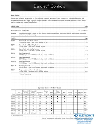
Dynatec® Series Selection Guide
Sold & Serviced By:
Warner® is a registered trademark of Warner Electric/Colfax Power Transmission Group
* Warner® Interchange
Channel 1 Channel 2 Contact Opto-
Input Output Output Maximum Cold Status isolated Anti- Torque Over- Soft Start Page
Model Voltage AC Voltage DC Voltage DC Current Switching LED’s DC Switching Overlap Adjust excite Soft Stop No.
D2950 115 90 90 1A ● ● ● ● ● K-2
D2750 115 90 90 1A ● ● ● ● ● K-4
D2550 115 90 90 1A ● ● ● ● K-6
D2100 115 90 90 2A ● ● K-8
D2110 230 90 90 2A ● ● K-8
D2101* 115 90 90 2A ● ● K-10
D2111* 230 90 90 2A ● ● K-10
D2650 115 0-90 adj 0-90 adj 1A ● ● ● ● K-12
ELECTROMATE
Toll Free Phone (877) SERVO98
Toll Free Fax (877) SERV099
www.electromate.com
sales@electromate.com
2. K-2
Dynatec® 2950 Control
Dual Channel Overexcite Clutch/Brake Control
Specifi cations
Power Input
Voltage: 115 VAC
Current: 1.5 amp
Frequency: 50/60 Hz
Fusing: Customer-supplied 2 amp
Power Output
Voltage: 90 VDC (105 V actual)
Overexcite Pulse: 325 VDC
Current: 1.0 Max.
D2950 Dimensions
Weight: 17 Oz.
Overall: 3.94" W. x 2.76" H. x 5.28" D.
Mounting: Din rail
Temperature
Operating: 0° to 65°C (32° to 149°F)
Description
The Dynatec® 2950 (D2950) is a solid-state digital Overexcite
(OE) clutch/brake controller, designed to operate 90 VDC clutch/
brake (C/B) coils with current loads of up to 1.0 amp; Din rail
mounting for ease of installation.
This controller operates one or two C/B coils with an adjustable
anti-overlap circuit and OE.
The D2950 incorporates voltage protection on the AC input.
When transient voltage spikes or notching is present on AC lines,
an isolation transformer is required to fi lter the incoming power
to the D2950.
Features
• Meets Certifi cation
• Adjustable clutch/brake “on” delay
Anti-overlap potentiometer
0 to 100 ms
• Status/Diagnostic lights:
Clutch On
Brake On
• Selective input switching logic
Cold contact, 3 - 30 VDC or 115 VAC
• Outputs (2) 1 amp Max load
• Use with all Dynacorp® 90 V products, except
308HQ, 310HQ, and 312HQ models.
Dynatec® Controls
115 VAC, 50/60 Hz
3-30 VDC
Contact Closure
Part No.
214277-040-2211
214277-040-2212
214277-040-2213
Input Logic
Sold & Serviced By:
ELECTROMATE
Toll Free Phone (877) SERVO98
Toll Free Fax (877) SERV099
www.electromate.com
sales@electromate.com
3. K-3
D2950 Overexcite
Overexcite produces a 270 VDC spike to the clutch or
brake. This graph displays RPM curve of clutch brake
package with No Overexcite.
The Dynatec® 2950 incorporates an Overexcite feature.
The results of Overexcite are displayed in the graph.
The clutch and brake coils are saturated much faster,
allowing for quick positive engagement, producing higher
start/stop accuracy, while reducing friction heat.
D2950 Anti-Overlap
When using conventional controls where the output voltage
is switched by a relay contact, overlap occurs when you
see the arching across the contacts. This indicates that just
for an instant the brake and clutch are both engaged. This
graph represents overlap. The effect of this is excessive wear
and heat to the clutch/brake system.
The Dynatec® 2950 incorporates MOV’s and an adjustable
time delay logic that will prevent the effects of overlap. This
graph illustrates the effects of anti-overlap. Notice the differ-ence
between the RPM curves. You have a shorter time to
speed and time to zero, and the switching is more precise,
creating less heat. These controls can actually operate the
clutch/brake system at higher cycle rates, with better repeat-ability
and less heat than conventional controls.
Dynatec® Controls
Zero RPM
Run RPM
Clutch/Brake
Shaft Rotation
Time
to
Speed
Time
to
Zero
Clutch/Brake Shaft RPM Curve using Conventional Control
Zero RPM
Run RPM
Clutch/Brake
Shaft Rotation
Time
to
Speed
Time
to
Zero
Clutch/Brake Shaft RPM Curve using Dynacorp® Control with Overexcite
Brake
Off
Zero RPM
Supply Voltage
90 V DC
Clutch/Brake
Shaft Rotation
Clutch
On
Time
to
Speed
Clutch
Off
p
Clutch
On
Brake
On
Time
to
Zero
Clutch/Brake Shaft RPM Curve using Conventional Control
Brake
Off
Zero RPM
Run RPM
Clutch
Off
Run RPM
Supply Voltage
90 V DC
Clutch/Brake
Shaft Rotation
Clutch
On
Time
to
Speed
p
Clutch
On
Brake
On
Time
to
Zero
Clutch/Brake Shaft RPM Curve using Dynacorp® Control with Anti-Overlap
D2950 Wiring Information
115 VAC 50/60 Hz
Contact
3-32 VDC
L1 L2 1 2 3
D2950
A B C 4 5 6 7
90 VDC Brake
90 VDC Clutch
Wiring example for logic input 3-32 VDC
115 VAC 50/60 Hz
Contact
115 VAC
L1 L2 1 2 3
D2950
A B C 4 5 6 7
90 VDC Brake
90 VDC Clutch
Wiring example for logic input 115 VAC
115 VAC 50/60 Hz
Contact
L1 L2 1 2 3
D2950
A B C 4 5 6 7
90 VDC Brake
90 VDC Clutch
Wiring example for contact closure
B Orange Wire Brake
White Wire Clutch
Orange Wire
White Wire Clutch
A
C
Dynacorp® Clutch/Brake Package Wiring
90 V DC Brake
90 V DC Clutch
B
A
C
Single Clutch and Brake Wiring
Sold & Serviced By:
ELECTROMATE
Toll Free Phone (877) SERVO98
Toll Free Fax (877) SERV099
www.electromate.com
sales@electromate.com
4. K-4
Dynatec® 2750 Control
Accel/Decel Dual Channel Clutch/Brake Control
Features
• Meets Certifi cation
• Soft-Start and Soft-Stop
(Ramps output from 0-2 seconds)
• Anti-Overlap Circuit
• 115 VAC Input
• Selective Input Switching Logic
Contact or Opto-Isolated 3-30 VDC or 115 VAC
• Status/Diagnostic lights:
Clutch On
Brake On
Specifi cations
Power Input
Voltage 115 VAC
Current 1.5 amp
Frequency 50/60 HZ
Fusing Customer-supplied 2 amp
Power Output
Voltage 0-90 VDC
Current 1.0 amp Max.
D2750 with Subpanel Dimensions
Weight 18 oz.
Overall 2.76" H. x 3.94" H. x 5.28" D.
Temperature
Operating: 0° to 65°C (32° to 149°F)
Description
The Dynatec® 2750 (D2750) is a solid-state, digitally designed
accel/decel clutch/brake controller, engineered to precisely
operate 90 VDC clutch/brake (C/B) coils with current loads of
up to 1.0 amp and din rail mounting for ease of installation.
This controller operates one or two coils, incorporating an
anti-overlap circuit.
The D2750 controller employs technology to ensure long life
and reliable service: The D2750 incorporates voltage protection
on the AC input. When transient voltage spikes or notching is
present on AC lines, an isolation transformer is required to fi lter
the incoming power to the D2750.
Sold & Serviced By:
ISO-9001 certifi ed
Dynatec® Controls
115 VAC, 50/60 Hz
3-30 VDC
Contact Closure
Part No.
214257-040-2230
214257-040-2231
214257-040-2232
Input Logic
ELECTROMATE
Toll Free Phone (877) SERVO98
Toll Free Fax (877) SERV099
www.electromate.com
sales@electromate.com
5. K-5
D2750 Anti-Overlap
When using conventional controls where the output voltage
is switched by a relay contact, overlap occurs when you
see the arching across the contacts. This indicates that just
for an instant the brake and clutch are both engaged. This
graph represents overlap. The effect of this is excessive wear
and heat to the clutch/brake system.
The Dynatec® 2750 incorporates MOV’s and time
delay logic that will prevent the effects of overlap. This
graph illustrates the effects of anti-overlap. Notice the
difference between the RPM curves. You have a shorter
time to speed and time to zero, and the switching
is more precise, creating less heat. These controls can
actually operate the clutch/brake system at higher cycle
rates, with better repeatability and less heat than conven-tional
controls.
D2750 Soft-Start/Soft-Stop
This feature is used to cushion the engagement of the
clutch and brake by ramping the voltage. This graph dis-plays
the RPM curve of a clutch brake package with No
Soft-Start/Soft-Stop.
The Dynatec® 2750 incorporates a Soft-Start/Soft-Stop
feature. This illustration displays the voltage ramping up and
ramping down. The ramp time is adjustable by turning the
Soft-Start potentiometer for clutch and Soft-Stop for brake
and can be adjusted from 0 to 2 seconds, which is the
elapsed time from 0 to 90 VDC. There are several factors
that are taken into consideration when using this feature:
Inertia, Cycle Rate, RPM and Load Torque.
Adjust the clutch or brake potentiometer to the desired
ramp time.
Dynatec® Controls
Brake
Off
Zero RPM
Supply Voltage
90 V DC
Clutch/Brake
Shaft Rotation
Clutch
On
Time
to
Speed
Overlap
Clutch
Off
Clutch
On
Brake
On
Time
to
Zero
Clutch/Brake Shaft RPM Curve using Conventional Control
Brake
Off
Zero RPM
No Overlap
Run RPM
Clutch
Off
Run RPM
Supply Voltage
90 V DC
Clutch/Brake
Shaft Rotation
Clutch
On
Time
to
Speed
Clutch
On
Brake
On
Time
to
Zero
Clutch/Brake Shaft RPM Curve using Dynacorp® Control with Anti-Overlap
Zero RPM
Run RPM
Clutch/Brake
Shaft Rotation
Time
to
Speed
Time
to
Zero
Clutch/Brake Shaft RPM Curve using Conventional Control
Zero RPM
Run RPM
Clutch/Brake Shaft RPM Curve using a Dynacorp® Control
with Soft-Start and Soft-Stop
Clutch/Brake
Shaft Rotation
Time
to
Speed
Time
to
Zero
D2750 Wiring Information
L2
115 VAC 50/60 Hz
L1
Contact
3-32 VDC
L1 L2 D2750 1 2 3
Min. Max. Min. Max.
Ramp Ramp
A B C
90 VDC Brake
90 VDC Clutch
Wiring example for logic input 3-32 VDC
L2
115 VAC 50/60 Hz
L1
Contact
115 VAC
D2750
L1 L2 1 2 3
Min. Max. Min. Max.
Ramp Ramp
A B C
90 VDC Brake
90 VDC Clutch
Wiring example for logic input 115 VAC
L2
115 VAC 50/60 Hz
L1
Contact
L1 L2 D2750 1 2 3
Min. Max. Min. Max.
Ramp Ramp
A B C
90 VDC Brake
90 VDC Clutch
Wiring example for contact closure
B Orange Wire Brake
White Wire Clutch
Orange Wire
White Wire Clutch
A
C
Dynacorp® Clutch/Brake Package Wiring
90 V DC Brake
90 V DC Clutch
B
A
C
Single Clutch and Brake Wiring
Sold & Serviced By:
ELECTROMATE
Toll Free Phone (877) SERVO98
Toll Free Fax (877) SERV099
www.electromate.com
sales@electromate.com
6. K-6
Dynatec® 2550 Control
Dual Channel Anti-Overlap Clutch/Brake Control
Description:
The Dynatec® 2550 (D2550) is a solid-state anti-overlap clutch/
brake controller, engineered to operate 90 VDC clutch/brake
(C/B) coils with current loads up to 1.0 amp; Din rail mounting
for ease of installation.
This controller operates one or two coils, incorporating an
anti-overlap circuit.
The D2550 incorporates voltage protection on the AC input.
When transient voltage spikes or notching is present on AC lines,
an isolation transformer is required to fi lter the incoming power
to the D2550.
Features:
• Meets Certifi cation
• Anti-Overlap Circuit
• 115 VAC Input
• Selective Input Switching Logic
Cold Contact or Opto-Isolated 3-30 VDC or 115 VAC
• Status/Diagnostic lights:
Clutch On
Brake On
Specifi cations
Power Input
Voltage 115 VAC
Current 1.5 amp
Frequency 50/60 HZ
Fusing Customer-supplied 2 amp
Power Output
Voltage 90 VDC
Current 1.0 amp Max.
D2550 with Sub-Panel Dimensions
Weight 15 oz.
Overall 2.76" H. x 1.97" W. x 4.30" D.
Temperature
Operating 0° to 65°C (32° to 149°F)
Sold & Serviced By:
ISO-9001 certifi ed
Dynatec® Controls
115 VAC, 50/60 Hz
3-30 VDC
Contact Closure
Part No.
214247-040-2201
214247-040-2202
214247-040-2203
Input Logic
ELECTROMATE
Toll Free Phone (877) SERVO98
Toll Free Fax (877) SERV099
www.electromate.com
sales@electromate.com
7. K-7
D2550 Anti-Overlap
When using conventional controls where the output voltage
is switched by a relay contact, overlap occurs when you
see the arching across the contacts. This indicates that just
for an instant the brake and clutch are both engaged. This
graph represents overlap. The effect of this is excessive wear
and heat to the clutch/brake system.
The Dynatec® 2550 incorporates MOV’s and time
delay logic that will prevent the effects of overlap. This
graph illustrates the effects of anti-overlap. Notice the
difference between the RPM curves. You have a shorter
time to speed and time to zero, and the switching
is more precise, creating less heat. These controls can
actually operate the clutch/brake system at higher cycle
rates with better repeatability and less heat than conven-tional
controls.
D2550 Wiring Information
Dynatec® Controls
Brake
Off
Zero RPM
Supply Voltage
90 V DC
Clutch/Brake
Shaft Rotation
Clutch
On
Time
to
Speed
Overlap
Clutch
Off
Clutch
On
Brake
On
Time
to
Zero
Clutch/Brake Shaft RPM Curve using Conventional Control
Brake
Off
Zero RPM
No Overlap
Run RPM
Clutch
Off
Run RPM
Supply Voltage
90 V DC
Clutch/Brake
Shaft Rotation
Clutch
On
Time
to
Speed
Clutch
On
Brake
On
Time
to
Zero
Clutch/Brake Shaft RPM Curve using Dynacorp® Control with Anti-Overlap
L1 L2 1 2 3
D2550
L2
115 VAC 50/60 Hz
L3
Contact
3-32 VDC
Fuse
90 VDC Brake
90 VDC Clutch
A B C Rt Rt
Rt
Wiring example for logic input 3-32 VDC
L1 L2 1 2 3
D2550
L2
115 VAC 50/60 Hz
L3
Contact
115 VAC
Fuse
90 VDC Brake
90 VDC Clutch
A B C Rt Rt
Rt
Wiring example for logic input 115 VAC
L1 L2 1 2 3
D2550
L2
115 VAC 50/60 Hz
L3
Contact
Fuse
90 VDC Brake
90 VDC Clutch
A B C Rt Rt
Rt
Wiring example for contact closures
B Orange Wire Brake
White Wire Clutch
Orange Wire
White Wire Clutch
A
C
Dynacorp® Clutch/Brake Package Wiring
90 V DC Brake
90 V DC Clutch
B
A
C
Sold & Serviced By:
Single Clutch and Brake Wiring
ELECTROMATE
Toll Free Phone (877) SERVO98
Toll Free Fax (877) SERV099
www.electromate.com
sales@electromate.com
8. K-8
Dynatec® D2100 and D2110
Plug-in Clutch/Brake Controls
Dynacorp® D2100 Control Part# 214215 (115 VAC Input)
Dynacorp® D2110 Control Part# 224215 (230 VAC Input)
Features:
• Meets Certifi cation
• Status/Diagnostic LED’S:
1. Green–Clutch ON
2. Red–Brake ON
• The D2100 and D2110 are protected from transient high
voltage spikes with MOV technology.
Specifi cations:
Model D2100
Part# 214215
Input V 115 VAC 50/60Hz
Output V 90 V DC
Output A 2 A Max.
Fuse 3 A, 250 VAC Micro-Fuse
Model D2110
Part# 224215
Input V 230 VAC 50/60Hz
Output V 90 V DC
Output A 2 A Max.
Fuse 3 A, 250 VAC Micro-Fuse
Optional Parts:
Part# 65-22-3
8 Pin Octal Socket
Part# 32-1-11 (Pack of 5)
3 A, 250 VAC (2 AG) F/A Micro-Fuse
Description:
The Dynatec® 2100 (D2100) and 2110 (D2110), are
plug-in controls, designed to mount into an eight pin octo-socket.
The D2100 and the D2110 are engineered to operate a 90 V
DC clutch and/or brake coil with current loads up to 2.0 amps.
The compact plug-in design allows for ease of installation and
replacement.
The D2100 and D2110 are fused on both input power lines to
protect the controller system. These controls incorporate voltage
protection on the AC input to suppress transient spikes, present
on some power lines.
Sold & Serviced By:
ISO-9001 certifi ed
Dynatec® Controls
ELECTROMATE
Toll Free Phone (877) SERVO98
Toll Free Fax (877) SERV099
www.electromate.com
sales@electromate.com
9. K-9
D2100/D2110 Wiring Information
Control Dimensions
Wiring Diagram
For Clutch and or Brake
7
8
1
2
SPDT Switch 10 A,
230 VAC Rated Contact
Supplied by Customer
Notice: Use wire and methods in accordance with Local, State, and National Electric Codes (NEC).
Base (Part # 65-22-3) ordered separately
6
5
4
D2100 = 115 VAC 3
Inputs
D2110 = 230 VAC
Clutch
Brake
Clutch
3 A, 250 V, 2 AG Fuses
One on Each Side Brake
Optional 8 Pin
Octal Socket
Dynacorp® Part#
65-22-3
Dynatec® Controls
Sold & Serviced By:
ELECTROMATE
Toll Free Phone (877) SERVO98
Toll Free Fax (877) SERV099
www.electromate.com
sales@electromate.com
10. K-10
Dynatec® D2101 and D2111
Plug-in Clutch/Brake Controls
Dynacorp® D2101 Control Part# D6001-448-004 (115 VAC Input)
Dynacorp® D2111 Control Part# D6001-448-006 (230 VAC Input)
Features:
• Meets Certifi cation
• Status/Diagnostic LED’S:
1. Green–Clutch ON
2. Red–Brake ON
• The D2101 and D2111 are protected from transient high
voltage spikes with MOV technology.
Specifi cations:
Model D2101
Part# D6001-448-004
Input V 115 VAC 50/60Hz
Output V 90 V DC
Output A 2 A Max.
Fuse 3 A, 250 VAC Micro-Fuse
Model D2111
Part# D6001-448-006
Input V 230 VAC 50/60Hz
Output V 90 V DC
Output A 2 A Max.
Fuse 3 A, 250 VAC Micro-Fuse
Optional Parts:
Part# 65-22-3
8 Pin Octal Socket
Part# 32-1-11 (Pack of 5)
3 A, 250 VAC (2 AG) F/A Micro-Fuse
Description:
The Dynatec® 2101 (D2101) and 2111 (D2111), are plug-in
controls, designed to mount into an eight pin octo-socket. The
D2101 and the D2111 are engineered to operate a 90 V
DC clutch and/or brake coil with current loads up to 2.0
amps. The compact plug-in design allows for ease of installation
and replacement.
The D2101 and D2111 are fused on both input power lines to
protect the controller system. These controls incorporate voltage
protection on the AC input to suppress transient spikes, present
on some power lines.
Sold & Serviced By:
ISO-9001 certifi ed
Dynatec® Controls
ELECTROMATE
Toll Free Phone (877) SERVO98
Toll Free Fax (877) SERV099
www.electromate.com
sales@electromate.com
11. K-11
D2101/D2111 Wiring Information
Optional 8 Pin
Octal Socket
6
5
4
D2101 = 115 VAC
Dynacorp® Part#
3 Inputs
65-22-3
D2111 = 230 VAC
Control Dimensions
Wiring Diagram
For Clutch and or Brake
7
8
1
2
Notice: Use wire and methods in accordance with Local, State, and National Electric Codes (NEC).
Base (Part # 65-22-3) ordered separately
SPDT Switch 10 A,
230 VAC Rated Contact
Supplied by Customer
Clutch
Brake
Clutch
3 A, 250 V, 2 AG Fuses
One on Each Side Brake
Dynatec® Controls
Sold & Serviced By:
ELECTROMATE
Toll Free Phone (877) SERVO98
Toll Free Fax (877) SERV099
www.electromate.com
sales@electromate.com
12. K-12
Dynatec® 2650 Control
Dual Channel Anti-Overlap
Torque Adjust Clutch/Brake Control
Specifi cations
Power Input
Voltage 115 VAC
Current 1.5 amp
Frequency 50/60 HZ
Fusing Customer-supplied 2 amp
Power Output
Voltage 90 VDC
Current 1.0 amp Max.
D2650 Dimensions
Weight 15 oz.
Overall 2.76" H. x 1.97" W. x 4.30" D.
Temperature
Operating 0° to 65°C (32° to 149°F)
Description
The Dynatec® 2650 (D2650) is a solid-state anti-overlap clutch/
brake controller, engineered to operate 90 VDC clutch/brake
(C/B) coils with current loads up to 1.0 amp; Din rail mounting
for ease of installation.
This controller operates one or two coils, incorporating adjustable
output voltage (torque) for each channel and anti-overlap circuit.
The D2650 incorporates voltage protection on the AC input.
When transient voltage spikes or notching is present on AC lines,
an isolation transformer is required to fi lter the incoming power
to the D2650.
Features
• Meets Certifi cation
• Anti-Overlap Circuit
• Dual Output Torque (Voltage) Adjustment
• 115 VAC Input
• Selective Input Switching Logic –115 VAC
• Status/Diagnostic LED’S:
1. Clutch ON
2. Brake ON
Dynatec® Controls
115 VAC, 50/60 Hz
Part No.
214237-040-2233
Input Logic
Sold & Serviced By:
ELECTROMATE
Toll Free Phone (877) SERVO98
Toll Free Fax (877) SERV099
www.electromate.com
sales@electromate.com
13. K-13
D2650 Anti-Overlap
When using conventional controls where the output voltage
is switched by a relay contact, overlap occurs when you
see the arching across the contacts. This indicates that just
for an instant the brake and clutch are both engaged. This
graph represents overlap. The effect of this is excessive wear
and heat to the clutch/brake system.
The Dynatec® 2650 incorporates MOV’s and time
delay logic that will prevent the effects of overlap. This
graph illustrates the effects of anti-overlap. Notice the
difference between the RPM curves. You have a shorter
time to speed and time to zero, and the switching
is more precise, creating less heat. These controls can
actually operate the clutch/brake system at higher cycle
rates, with better repeatability and less heat than conven-tional
controls.
Dynatec® Controls
Brake
Off
Zero RPM
Supply Voltage
90 V DC
Clutch/Brake
Shaft Rotation
Clutch
On
Time
to
Speed
Overlap
Clutch
Off
Clutch
On
Brake
On
Time
to
Zero
Clutch/Brake Shaft RPM Curve using Conventional Control
Brake
Off
Zero RPM
No Overlap
Run RPM
Clutch
Off
Run RPM
Supply Voltage
90 V DC
Clutch/Brake
Shaft Rotation
Clutch
On
Time
to
Speed
Clutch
On
Brake
On
Time
to
Zero
Clutch/Brake Shaft RPM Curve using Dynacorp® Control with Anti-Overlap
D2650 Wiring Information
L1 L2 1 2
D2650
L2
120 VAC 50/60 Hz
L1
Contact
120 VAC
Fuse
90 VDC Brake
90 VDC Clutch
A B C Rt Rt
Rt
B Orange Wire Brake
White Wire Clutch
Orange Wire
White Wire Clutch
A
C
Dynacorp® Clutch/Brake Package Wiring
90 V DC Brake
90 V DC Clutch
B
A
C
Single Clutch and Brake Wiring
Sold & Serviced By:
ELECTROMATE
Toll Free Phone (877) SERVO98
Toll Free Fax (877) SERV099
www.electromate.com
sales@electromate.com