SlideShare uma empresa Scribd logo
1 de 20
Baixar para ler offline
Dust-proof/Splash-proof Type 
RCP2W 
RCAW 
RCS2W 
RRCCPP22WW-RRAA1100CC 
RCP2W-SA16C 
RCP2W-RA4C 
RCP2W-RA6C 
RCAW-RA3C RCAW/RCS2W-RA4C 
441 Dust-proof/Splash-proof Type 
Sold & Serviced By: 
ELECTROMATE 
Toll Free Phone (877) SERVO98 
Toll Free Fax (877) SERV099 
www.electromate.com 
sales@electromate.com
RCP2W 
series 
Pulse Motor 
Type 
RCAW 
series 
24V 
Servo Motor 
Type 
RCS2W 
series 
200V 
Servo Motor 
Type 
Dust-proof/Splash-proof Type 
Slider Type Coupled 158mm width RCP2W-SA16C 
Rod Type Coupled 45mm width RCP2W-RA4C 
64mm width RCP2W-RA6C 
High-thrust Type 100mm width RCP2W-RA10C 
Gripper Type Mini Slider Type 42mm width RCP2W-GRSS 
Mini Lever type 42mm width RCP2W-GRLS 
Rod Type Coupled ø32mm RCAW-RA3C 
Built-in ø32mm RCAW-RA3D 
Motor Side-mounted ø32mm RCAW-RA3R 
Rod Type Coupled ø37mm RCAW-RA4C 
Built-in ø37mm RCAW-RA4D 
Motor Side-mounted ø37mm RCAW-RA4R 
Rod Type Coupled ø37mm RCS2W-RA4C 
Built-in ø37mm RCS2W-RA4D 
Motor Side-mounted ø37mm RCS2W-RA4R 
443 
445 
447 
449 
451 
453 
455 
457 
459 
Dust-proof/Splash-proof Type 442 
Slider 
Type 
Mini 
Standard 
Controllers 
Integrated 
Rod 
Type 
Mini 
Standard 
Controllers 
Integrated 
Table/Arm 
/Flat Type 
Mini 
Standard 
Gripper/ 
Rotary Type 
Linear Servo 
Type 
Cleanroom 
Type 
Splash-Proof 
Controllers 
PMEC 
/AMEC 
PSEP 
/ASEP 
ROBO 
NET 
ERC2 
PCON 
ACON 
SCON 
PSEL 
ASEL 
SSEL 
XSEL 
Pulse Motor 
Servo Motor 
(24V) 
Servo Motor 
(200V) 
Linear 
Servo Motor 
Sold & Serviced By: 
ELECTROMATE 
Toll Free Phone (877) SERVO98 
Toll Free Fax (877) SERV099 
www.electromate.com 
sales@electromate.com
RCP2W ROBO Cylinder 
RCP2W-SA16C 
ROBO Cylinder Water-proof Slider Type 158mm Width Pulse Motor Coupled 
■ Configuration: RCP2W SA16C I 86P P2 
Series Type Encoder Motor Lead Stroke Compatible Controllers Cable Length Option 
* See page Pre-35 for explanation of each code that makes up the configuration name. 
O I N 
50 
100 
150 
200 
250 
300 
350 
400 
450 
500 
550 
600 
4mm lead 
Type Cable Symbol Standard Price 
Standard 
Special Lengths 
Robot Cable 
P (1m) 
S (3m) 
M (5m) 
X06 (6m) ~ X10 (10m) 
X11 (11m) ~ X15 (15m) 
X16 (16m) ~ X20 (20m) 
R01 (1m) ~ R03 (3m) 
R04 (4m) ~ R05 (5m) 
R06 (6m) ~ R10 (10m) 
R11 (11m) ~ R15 (15m) 
R16 (16m) ~ R20 (20m) 
− 
− 
− 
− 
− 
− 
− 
− 
− 
− 
− 
* See page A-39 for cables for maintenance. 
P. A-5 Technical 
References 
Max. Load Capacity (Note 1) 
Note 
■ Speed vs. Load Capacity 
Due to the characteristics of the Pulse motor, the RCP2 series' load 
capacity decreases at high speeds. In the table below, check if your 
desired speed and load capacity are supported. 
Speed (mm/sec) 
40 
35 
30 
25 
20 
15 
10 
5 
0 
0 25 50 75 100 125 150 175 200 
Load Capacity (kg) 
8mm lead 
1 Stroke List 2 Cable List 
3 Option List 
Actuator Specifications 
Wi thout cover Wi th cover 
Name Option Code See Page Standard Price 
CO 
NM 
→ 444 
→ A-33 
With cover 
Reversed-home 
− 
− 
(Unit: mm/s) 
Actuator Specifications 
■ Lead and Load Capacity (Note 1) Please note that the maximum load capacity decreases as the speed increases. ■ Stroke and Maximum Speed 
Stroke 
Lead 
50~600 
(50mm increments) 
180 
133 
8 
4 
Legend 1 Stroke 2 Cable length 3 Options 
Lead 
(mm) 
8 
4 
Horizontal (kg) 
~25 
~35 
Vertical (kg) 
Model 
Not Allowed 
Stroke 
(mm) 
50~600 
(50mm 
increments) 
− 
− 
− 
− 
− 
− 
− 
− 
− 
− 
− 
− 
− 
− 
− 
− 
− 
− 
− 
− 
− 
− 
− 
− 
Item Descr ipt ion 
Ball screw ø12mm C10 grade 
±0.08mm 
0.1 mm or less 
ø20 Non-lubricated Linear Sliding Guide 
20.0N・m 
Ma direction 200mm or less 
IP67 
0~40°C, 85%RH or less (Non-condensing) 
Drive System 
Positioning Repeatability 
Lost Motion 
Guide 
Allowable Static Load Moment 
Overhang Load Length 
Protection Structure 
Ambient Operating Temp./Humidity 
A dynamic moment isn't applicable for the SA16C for structural reasons. 
When an object is to be mounted on the slider, please fix it in a manner so that no moment 
load is applied in the direction Mb or Mc, and so that the load is distributed evenly. 
RCP2W-SA16C-I-86P-8- 1 -P2- 2 - 3 
RCP2W-SA16C-I-86P-4- 1 -P2- 2 - 3 
P 
T 
Notes on 
Selection 
(1) The actuator is limited to being installed horizontally. Please note that it can't be used when 
installed in a wrong direction (transverse, vertical or reverse). (The same goes for storage.) 
(2) When the stroke increases, the maximum speed will drop to prevent the ball screw from 
reaching the critical rotational speed. 
Use the actuator specification table below to check the maximum speed at the stroke you 
desire. 
(3) Since the RCP2 series use a pulse motor, the load capacity decreases at high speeds. 
Check in the Speed vs. Load Capacity graph to see if your desired speed and load capacity 
are supported. 
(4) The load capacity is based on operation at an acceleration of 0.2G. 
0.2G is the upper limit for the acceleration. 
(5) The cable joint connector is not splash-proof; secure it in a place that is not prone to water 
spills. 
Stroke (mm) 
Standard Price 
86P: Pulse motor 
56 □ High Output 
I: Incremental 
Type 
N : None 
P : 1m 
S : 3m 
M : 5m 
X □□ : Custom Length 
R □□ : Robot Cable 
CO : With Cover 
NM : Reversed-home 
8 : 8mm 
4 : 4mm 
50 : 50mm P2: PCON-CF 
〜 
600 : 600mm 
(50mm pitch 
increments) 
443 RCP2W-SA16C 
Slider 
Type 
Mini 
Standard 
Controllers 
Integrated 
Rod 
Type 
Mini 
Standard 
Controllers 
Integrated 
Table/Arm 
/Flat Type 
Mini 
Standard 
Gripper/ 
Rotary Type 
Linear Servo 
Type 
Cleanroom 
Type 
Splash-Proof 
Controllers 
PMEC 
/AMEC 
PSEP 
/ASEP 
ROBO 
NET 
ERC2 
PCON 
ACON 
SCON 
PSEL 
ASEL 
SSEL 
XSEL 
Pulse Motor 
Servo Motor 
(24V) 
Servo Motor 
(200V) 
Linear 
Servo Motor 
Sold & Serviced By: 
ELECTROMATE 
Toll Free Phone (877) SERVO98 
Toll Free Fax (877) SERV099 
www.electromate.com 
sales@electromate.com
[No Cover] 
[With Cover] 
(Optional) 
15 
130 
20 20 
15 
RCP2W ROBO Cylinder 
155 
ø90 
(2m) 
90 
A 
B 
L 
65 65 
4-9 drilled, 
ø14 counterbore, depth 8.5 
2-ø8H7 depth 10 
S (Stroke) 
Home 
53 25 125 30 
5 
130 
4-M8 depth 20 
105 
80 
25 52 
115 
100 
158 
4 
Cable joint 
connector*1 
Actuator cable*3 
ME SE ME*2 
Base plate Slider Slider rod Base plate 
Guide rod Motor cover 
15 
130 
20 20 
15 
ø90 
155 
90 
A 
B 
L 
4-9 drilled, ø14 deep 65 65 
counterbore, depth 8.5 
2-ø8H10 depth 10 
S (Stroke) 78 125 30 
5 
130 
4-M8 depth 20 
105 
80 
77 
4 
115 
101.5 
166 
ME SE Home ME 
4.3±0.2 
7.3±0.2 
8 
6.5 
2 
A 
Details of A 
For Special Orders P. A-9 
Dimensions 
Stroke 50 100 150 200 250 300 350 400 450 500 550 600 
490 
335 
305 
50 
9 
10.5 
590 
435 
405 
150 
9.9 
11.8 
690 
535 
505 
250 
10.9 
13.2 
790 
635 
605 
350 
11.8 
14.6 
890 
735 
705 
450 
12.7 
15.9 
990 
835 
805 
550 
13.7 
17.3 
540 
385 
355 
100 
9.4 
11.1 
640 
485 
455 
200 
10.4 
12.5 
740 
585 
555 
300 
11.3 
13.8 
840 
685 
655 
400 
12.3 
15.3 
940 
785 
755 
500 
13.2 
16.6 
1040 
885 
855 
600 
15.1 
18.9 
■ Dimensions/Weight by Stroke 
※ For the reverse-home 
model, the dimensions 
(distance to home) on the 
motor-side and that on the 
opposite side are flipped. 
*1 A motor-encoder cable is 
connected here. Please note 
that motor cable is the same as 
the one in the RCP2 series, but 
that the encoder cable is a 
dedicated type. The cable joint 
connector is not splash-proof; 
therefore, please secure it in a 
place that is not prone to water 
spills. 
*2 When homing, the slider 
moves to the ME; therefore, 
please watch for any 
interference with the 
surrounding objects. 
ME: Mechanical end 
SE: Stroke end 
*3 The actuator cable is not a 
robot cable (flex resistant 
cable); therefore, please don't 
use it for movable parts such 
as in cable track. 
Compatible Controllers 
The controller for the RCP2W-SA16C type is a dedicated controller. 
Name External View Model Description Max. Positioning Points Input Voltage Power Supply Capacity Standard Price See Page 
Positioner 
Type 
Positioning 
possible for 
up to 512 points 
512 points DC24V 
L 
A 
B 
S 
Weight without cover (kg) 
Weight with cover (kg) 
PCON-CF-86PI-NP-2-0 6A max. − → P525 
Note: Please note that the encoder cable is a dedicated CF-type cable that is different from the PCON-C/CG/CY/PL/PO/SE controllers. 
RCP2W-SA16C 444 
Slider 
Type 
Mini 
Standard 
Controllers 
Integrated 
Rod 
Type 
Mini 
Standard 
Controllers 
Integrated 
Table/Arm 
/Flat Type 
Mini 
Standard 
Gripper/ 
Rotary Type 
Linear Servo 
Type 
Cleanroom 
Type 
Splash-Proof 
Controllers 
PMEC 
/AMEC 
PSEP 
/ASEP 
ROBO 
NET 
ERC2 
PCON 
ACON 
SCON 
PSEL 
ASEL 
SSEL 
XSEL 
Pulse Motor 
Servo Motor 
(24V) 
Servo Motor 
(200V) 
Linear 
Servo Motor 
Sold & Serviced By: 
ELECTROMATE 
Toll Free Phone (877) SERVO98 
Toll Free Fax (877) SERV099 
www.electromate.com 
sales@electromate.com
RCP2W ROBO Cylinder 
RCP2W-RA4C ROBO Cylinder Splash-proof Rod Type 45mm Width Pulse Motor Coupled 
■ Speed vs. Load Capacity 
300 400 500 600 700 
70 
60 
50 
40 
30 
20 
21 
18 
15 
12 
9 
6 
19 
* See page Pre-35 for explanation of each code that makes up the configuration name. 
O I N 
Actuator Specifications 
P. A-5 Technical 
References 
Model Stroke 
Legend 1 Stroke 2 Compatible controller 3 Cable length 4 Options 
Max. Load Capacity (Note 1) Maximum Push 
1 Stroke List 3 Cable List 
Type Cable Symbol Standard Price 
Standard 
Item Descr ipt ion 
Ball screw ø8mm C10 grade 
±0.02mm 
0.1 mm or less 
ø22mm 
±1.5 degrees 
IP65 
0~40°C, 85%RH or less (Non-condensing) 
Drive System 
Positioning Repeatability 
Lost Motion 
Rod diameter 
Rod non-rotational accuracy 
Protection Structure 
Ambient Operating Temp./Humidity 
Due to the characteristics of the Pulse motor, the RCP2 series' 
load capacity decreases at high speeds. In the table below, check 
if your desired speed and load capacity are supported. 
0 
0 100 200 
Speed (mm/sec) 
10 
Horizontal 
1L0emadm 1 l0ead 
2.5mm lead 
5mm lead 
25 
5 
Load Capacity (kg) 
00 50 100 150 200 250 300 350 
Speed (mm/sec) 
3 
Vertical 
Lead 10 
Lead 2.5 
5mm lead 
10mm lead 
2.5mm lead 
4.5 
2.5 2.5 2 
Load Capacity (kg) 
Special Lengths 
Robot Cable 
P (1m) 
S (3m) 
M (5m) 
X06 (6m ) ~ X10 (10m) 
X11 (11m) ~ X15 (15m) 
X16 (16m) ~ X20 (20m) 
R01 (1m) ~ R03 (3m) 
R04 (4m) ~ R05 (5m) 
R06 (6m) ~ R10 (10m) 
R11 (11m) ~ R15 (15m) 
R16 (16m) ~ R20 (20m) 
− 
− 
− 
− 
− 
− 
− 
− 
− 
− 
− 
* See page A-39 for cables for maintenance. 
4 Option List Actuator Specifications 
■ Stroke and Maximum Speed 
Stroke 
Lead 
50~200 
(50mm increments) 
450 
〈250〉 
190 
125 
〈115〉 
250 
450 
〈250〉 
190 
115 
300 
350 
〈250〉 
175 
85 
10 
5 
2.5 
− 
− 
− 
− 
− 
− 
50 
100 
150 
200 
250 
300 
Name Option Code See Page Standard Price 
B 
FL 
FT 
NM 
→ A-25 
→ A-27 
→ A-29 
→ A-33 
− 
− 
− 
− 
Brake-Equipped 
With Flange 
With Foot bracket 
Reversed-home 
(Unit: mm/s) 
■ Lead and Load Capacity (Note 1) Please note that the maximum load capacity decreases as the speed increases. 
Lead 
(mm) Horizontal ( k g ) Vertical (kg) 
Force 
(N) (Note 2) 
(mm) 
RCP2W-RA4C-I-42P-10- 1 - 2 - 3 - 4 
RCP2W-RA4C-I-42P-5- 1 - 2 - 3 - 4 
RCP2W-RA4C-I-42P-2.5- 1 - 2 - 3 - 4 
10 
5 
2.5 
~25 
40 
40 
~4.5 
~12 
~19 
150 
284 
358 
50~300 
(50mm 
increments) 
(Note 2) See page A-69 for push force graph. 
* The value inside < > applies to vertical setting. 
P 
T 
Notes on 
Selection 
(1) When the stroke increases, the maximum speed will drop to prevent the ball screw from reaching 
the critical rotational speed. Use the actuator specification table below to check the maximum 
speed at the stroke you desire. 
(2) Since the RCP2 series use a pulse motor, the load capacity decreases at high speeds. Check in the 
Speed vs. Load Capacity graph on the above right to see if your desired speed and load capacity 
are supported. 
(3) The load capacity is based on operation at an acceleration of 0.2G. 
0.2G is the upper limit for the acceleration. 
(4) The cable joint connector is not splash-proof; secure it in a place that is not prone to water spills. 
Stroke (mm) Standard Price 
42P: Pulse motor 
42 □ size 
I: Incremental Type 
* The simple 
absolute encoder 
is also considered 
type "I". 
N : None 
P : 1m 
S : 3m 
M : 5m 
X □□ : Custom 
R □□ : Robot Cable 
B : Brake-Equipped 
FL : With Flange 
FT : With Foot bracket 
NM : Reversed-home 
10 : 10mm 
5 : 5mm 
2.5 : 2.5mm 
■ Configuration: RCP2W RA4C I 42P 
Series Type Encoder Motor Lead Stroke Compatible Controllers Cable Length Option 
P1 : PCON 
RPCON 
PSEL 
P3 : PMEC 
PSEP 
50: 50mm 
〜 
300: 300mm 
(50mm pitch 
increments) 
445 RCP2W-RA4C 
Slider 
Type 
Mini 
Standard 
Controllers 
Integrated 
Rod 
Type 
Mini 
Standard 
Controllers 
Integrated 
Table/Arm 
/Flat Type 
Mini 
Standard 
Gripper/ 
Rotary Type 
Linear Servo 
Type 
Cleanroom 
Type 
Splash-Proof 
Controllers 
PMEC 
/AMEC 
PSEP 
/ASEP 
ROBO 
NET 
ERC2 
PCON 
ACON 
SCON 
PSEL 
ASEL 
SSEL 
XSEL 
Pulse Motor 
Servo Motor 
(24V) 
Servo Motor 
(200V) 
Linear 
Servo Motor 
Sold & Serviced By: 
ELECTROMATE 
Toll Free Phone (877) SERVO98 
Toll Free Fax (877) SERV099 
www.electromate.com 
sales@electromate.com
RCP2W ROBO Cylinder 
Cable joint connector *2 
Actuator cable*5 
7 
Square nut insertion inlet 
* 
M10X 1.25 
Secure at 
least 100 
Intake port*1 
(360 deg rotatable) 
Please don't apply an external force coming from a 
direction other than that of the rod's advance. 
The rotation stopper may break if a force coming from 
right angle or rotating direction is applied to the rod. 
7.5 (width across flats) 
4-M8 depth 12 
Home 
A Sec 
Dimensions of Supplied 
Nut for Rod Tip 
Effective T-slot range*4 
With Brake 
Note: 
Details of A Section 
Brake unit 
Rod 
diameter ø22 
24.3 
Dimensions of Supplied 
Square Nut for T-slot 
(4 nuts provided) 
Dimensions 
* Adding a brake increases overall length by 58mm 
and its weight by 0.4kg. 
2 Compatible Controllers 
The RCP2W series actuators can operate with the controllers below. Select the controller according to your usage. 
For Special Orders P. A-9 
Stroke 50 100 150 200 250 300 
ℓ 
L 
Weight (kg) 
132.5 
223 
1.9 
182.5 
273 
2.1 
232.5 
323 
2.2 
282.5 
373 
2.5 
332.5 
423 
2.9 
382.5 
473 
3.1 
■ Dimensions/Weight by Stroke 
* 1. Intake/exhaust port is the air exhaust tube in the main body. Insert OD ø6 mm 
tube and use it extended to a place that is not prone to water spills or intake. 
* 2. Connect motor encoder cable . See page A-39 for details on cables. 
The cable joint connector is not splash-proof; therefore, please secure it in a 
place that is not prone to water spills. 
* 3. When homing, the rod moves to the ME; therefore, please watch for any 
interference with the surrounding objects. 
ME:Mechanical End 
SE:Stroke end 
The dimensions enclosed in "( )" are reference dimensions. 
* 4. Please note that there is no T-slot in the bottom of brake unit. 
* 5. The actuator cable is not a robot cable (flex resistant cable); therefore, please don't 
use it for movable parts such as cable track. 
Name 
External 
View 
Model Description 
Max. 
Positioning 
Points 
Input 
Voltage 
Power 
Supply 
Capacity 
Standard Price See Page 
Solenoid 
Valve Type 
PMEC-C-42PI-NP-2- 1 Easy-to-use controller, 
even for beginners. 
3 points 
AC100V 
AC200V See P481 − → P477 
PSEP-C-42PI-NP-2-0 
Operable with same signal as 
solenoid valve. Supports both 
single and double solenoid 
types. 
No homing necessary with 
simple absolute type. 
DC24V 2A max. 
− 
→ P487 
Splash-Proof 
Solenoid Valve Type PSEP-CW-42PI-NP-2-0 − 
Positioner Type PCON-C-42PI-NP-2-0 
Positioning possible for 
up to 512 points 512 points 
− 
→ P525 
Safety Category 
Compliant 
Positioner Type 
PCON-CG-42PI-NP-2-0 − 
Pulse Train Input Type 
(Differential Line Driver) PCON-PL-42PI-NP-2-0 
Differential line driver 
support Pulse Train Input 
Type 
(−) 
− 
Pulse Train Input Type 
(Open Collector) PCON-PO-42PI-NP-2-0 Open Collector Pulse Train 
Input Type − 
Serial 
PCON-SE-42PI-N-0-0 Dedicated to serial 
Communication Type communication 64 points − 
Field Network Type RPCON-42P Dedicated to field network 768 points − → P503 
Program Control 
Type PSEL-C-1-42PI-NP-2-0 
Programmed operation is 
possible Can operate up to 
2 axes 
1500 points − → P557 
* This is for the single-axis PSEL. 
*1 is a placeholder for the power supply voltage (1:100V/2:100~240V). 
RCP2W-RA4C 446 
Slider 
Type 
Mini 
Standard 
Controllers 
Integrated 
Rod 
Type 
Mini 
Standard 
Controllers 
Integrated 
Table/Arm 
/Flat Type 
Mini 
Standard 
Gripper/ 
Rotary Type 
Linear Servo 
Type 
Cleanroom 
Type 
Splash-Proof 
Controllers 
PMEC 
/AMEC 
PSEP 
/ASEP 
ROBO 
NET 
ERC2 
PCON 
ACON 
SCON 
PSEL 
ASEL 
SSEL 
XSEL 
Pulse Motor 
Servo Motor 
(24V) 
Servo Motor 
(200V) 
Linear 
Servo Motor 
Sold & Serviced By: 
ELECTROMATE 
Toll Free Phone (877) SERVO98 
Toll Free Fax (877) SERV099 
www.electromate.com 
sales@electromate.com
RCP2W ROBO Cylinder 
RCP2W-RA6C ROBO Cylinder Splash-proof Rod Type 64mm Width Pulse Motor Coupled 
■ Speed vs. Load Capacity 
300 400 500 600 700 
70 
60 
50 
40 
30 
20 
4mm lead 
35 
30 
25 
20 
15 
10 
* See page Pre-35 for explanation of each code that makes up the configuration name. 
O I N 
Actuator Specifications 
P. A-5 Technical 
References 
Model Stroke 
Legend 1 Stroke 2 Compatible controller 3 Cable length 4 Options 
Max. Load Capacity (Note 1) Maximum Push 
■ Stroke and Maximum Speed 
1 Stroke List 3 Cable List 
Type Cable Symbol Standard Price 
Standard 
Item Descr ipt ion 
Ball screw ø12mm C10 grade 
±0.02mm 
0.1 mm or less 
ø30mm 
±1.0 degrees 
IP65 
0~40°C, 85%RH or less (Non-condensing) 
Drive System 
Positioning Repeatability 
Lost Motion 
Rod diameter 
Rod non-rotational accuracy 
Protection Structure 
Ambient Operating Temp./Humidity 
Due to the characteristics of the Pulse motor, the RCP2 series' 
load capacity decreases at high speeds. In the table below, 
check if your desired speed and load capacity are supported. 
0 
0 100 200 
Speed (mm/sec) 
10 
Horizontal 
16mm lead 
8mm lead 
16mm lead 
554mm Load Capacity (kg) 
00 50 100 150 200 250 300 350 
Speed (mm/sec) 
5 
Vertical 
8mm lead 
16mm lead 
4mm lead 
2 1 
26 
17.5 
Load Capacity (kg) 
Special Lengths 
Robot Cable 
P (1m) 
S (3m) 
M (5m) 
X06 (6m) ~ X10 (10m) 
X11 (11m) ~ X15 (15m) 
X16 (16m) ~ X20 (20m) 
R01 (1m) ~ R03 (3m) 
R04 (4m) ~ R05 (5m) 
R06 (6m) ~ R10 (10m) 
R11 (11m) ~ R15 (15m) 
R16 (16m) ~ R20 (20m) 
− 
− 
− 
− 
− 
− 
− 
− 
− 
− 
− 
* See page A-39 for cables for maintenance. 
− 
− 
− 
− 
− 
− 
50 
100 
150 
200 
250 
300 
4 Option List Actuator Specifications 
Name Opt ion Code See Page Standard Pr ice 
B 
FL 
FT 
NM 
→ A-25 
→ A-27 
→ A-29 
→ A-33 
− 
− 
− 
− 
Brake-Equipped 
With Flange 
With Foot bracket 
Reversed-home 
(Unit: mm/s) 
■ Lead and Load Capacity (Note 1) Please note that the maximum load capacity decreases as the speed increases. 
Lead 
(mm) Horizontal( k g ) Vertical(kg) 
Force 
(N) (Note 2) 
(mm) 
RCP2W-RA6C-I-56P-16- 1 - 2 - 3 - 4 
RCP2W-RA6C-I-56P-8- 1 - 2 - 3 - 4 
RCP2W-RA6C-I-56P-4- 1 - 2 - 3 - 4 
16 
8 
4 
~40 
50 
55 
~5 
~17.5 
~26 
240 
470 
800 
50~300 
(50mm 
increments) 
Stroke 
Lead 
50~300 
(50mm increments) 
320〈265〉 
200 
100 
16 
8 
4 
(Note 2) See page A-69 for push force graph. * The value inside < > applies to vertical setting. 
P 
T 
Notes on 
Selection 
(1) When the stroke increases, the maximum speed will drop to prevent the ball screw from reaching the 
critical rotational speed. Use the actuator specification table below to check the maximum speed at the 
stroke you desire. 
(2) Since the RCP2 series use the pulse motor, the load capacity decreases at high speeds. Check in the 
Speed vs. Load Capacity graph on the above right to see if your desired speed and load capacity are 
supported. 
(3) The load capacity is based on operation at an acceleration of 0.2G. 
0.2G is the upper limit for the acceleration. 
(4) The cable joint connector is not splash-proof; secure it in a place that is not prone to water spills. 
Stroke (mm) Standard Price 
56P: Pulse motor 
56 □ size 
I: Incremental Type 
* The simple 
absolute encoder 
is also considered 
type "I". 
N : None 
P : 1m 
S : 3m 
M : 5m 
X □□ : Custom Length 
R □□ : Robot Cable 
B : Brake-Equipped 
FL : With Flange 
FT : With Foot bracket 
NM : Reversed-home 
16 : 16mm 
8 : 8mm 
4 : 4mm 
■ Configuration: RCP2W RA6C I 56P 
Series Type Encoder Motor Lead Stroke Compatible Controllers Cable Length Option 
P1 : PCON 
RPCON 
PSEL 
P3 : PMEC 
PSEP 
50: 50mm 
〜 
300: 300mm 
(50mm pitch 
increments) 
447 RCP2W-RA6C 
Slider 
Type 
Mini 
Standard 
Controllers 
Integrated 
Rod 
Type 
Mini 
Standard 
Controllers 
Integrated 
Table/Arm 
/Flat Type 
Mini 
Standard 
Gripper/ 
Rotary Type 
Linear Servo 
Type 
Cleanroom 
Type 
Splash-Proof 
Controllers 
PMEC 
/AMEC 
PSEP 
/ASEP 
ROBO 
NET 
ERC2 
PCON 
ACON 
SCON 
PSEL 
ASEL 
SSEL 
XSEL 
Pulse Motor 
Servo Motor 
(24V) 
Servo Motor 
(200V) 
Linear 
Servo Motor 
Sold & Serviced By: 
ELECTROMATE 
Toll Free Phone (877) SERVO98 
Toll Free Fax (877) SERV099 
www.electromate.com 
sales@electromate.com
RCP2W ROBO Cylinder 
Actuator cable*5 
Intake port*1 
(360 deg rotatable) 
Square nut 
insertion inlet 
Dimensions of 
Supplied Nut 
for Rod Tip 
4-M8 depth 15 
A Sec. 
Please don't apply an external force 
coming from a direction other than 
that of the rod's advance. 
The rotation stopper may break if a 
force coming from right angle or 
rotating direction is applied to the rod. 
Dimensions of Supplied 
Square Nut for T-slot 
(4 nuts provided) 
Home ME *3 
Note: 
Details of A Section 
Hex Socket Bolt: 
4-M5X20 
Effective T-slot range*4 
With Brake 
Cable joint connector *2) 
Secure at 
least 100 
9.5 (width across flats) 
Brake unit 
Rod 
diameter ø30 
Dimensions 
* Adding a brake increases overall length by 72.5mm 
and its weight by 0.9kg. 
2 Compatible Controllers 
The RCP2W series actuators can operate with the controllers below. Select the controller according to your usage. 
For Special Orders P. A-9 
*1. Intake/exhaust port is the air exhaust tube in the main body. Insert OD ø6 mm 
tube and use it extended to a place that is not prone to water spills or intake. 
*2. Connect motor encoder cable . See page A-39 for details on cables. 
The cable joint connector is not splash-proof; therefore, please secure it in a 
place that is not prone to water spills. 
*3. When homing, the rod moves to the ME; therefore, please watch for any 
interference with the surrounding objects. 
ME: Mechanical End 
SE: Stroke end 
The dimensions enclosed in "( )" are reference dimensions. 
*4. Please note that there is no T-slot in the bottom of brake unit. 
*5. The actuator cable is not a robot cable (flex resistant cable); therefore, please 
don't use it for movable parts such as cable track. 
Stroke 50 100 150 200 250 300 
ℓ 
L 
Weight (kg) 
150 
266 
3.5 
200 
316 
4.0 
250 
366 
4.5 
300 
416 
5.0 
350 
466 
5.5 
400 
516 
6.0 
■ Dimensions/Weight by Stroke 
Name 
External 
View 
Model Description 
Max. 
Positioning 
Points 
Input 
Voltage 
Power 
Supply 
Capacity 
Standard Price See Page 
Solenoid Valve Type 
PMEC-C-56PI-NP-2-1 
Easy-to-use controller, 
even for beginners. 
3 points 
AC100V 
AC200V 
See P481 − → P477 
PSEP-C-56PI-NP-2-0 
Operable with same signal 
as solenoid valve. 
Supports both single and 
double solenoid types. 
No homing necessary with 
simple absolute type. 
DC24V 2A max. 
− 
→ P487 
Splash-Proof 
Solenoid ValveType PSEP-CW-56PI-NP-2-0 − 
Positioner Type PCON-C-56PI-NP-2-0 
Positioning possible for 
up to 512 points 512 points 
− 
→ P525 
Safety Category 
Compliant Positioner 
Type 
PCON-CG-56PI-NP-2-0 − 
Pulse Train Input ype 
(Differential Line 
Driver) 
PCON-PL-56PI-NP-2-0 
Differential line driver 
support Pulse Train 
Input Type 
(−) 
− 
Pulse Train Input 
Type (Open Collector) PCON-PO-56PI-NP-2-0 Open Collector Pulse 
Train Input Type − 
Serial 
Dedicated to serial 
Communication Type PCON-SE-56PI-N-0-0 communication 64 points − 
Field Network Type RPCON-56P Dedicated to field 
network 768 points − → P503 
Program Control 
Type PSEL-C-1-56PI-NP-2-0 
Programmed operation 
is possible Can operate 
up to 2 axes 
1500 points − → P557 
* This is for the single-axis PSEL. 
*1 is a placeholder for the power supply voltage (1:100V / 2:100~240V) 
RCP2W-RA6C 448 
Slider 
Type 
Mini 
Standard 
Controllers 
Integrated 
Rod 
Type 
Mini 
Standard 
Controllers 
Integrated 
Table/Arm 
/Flat Type 
Mini 
Standard 
Gripper/ 
Rotary Type 
Linear Servo 
Type 
Cleanroom 
Type 
Splash-Proof 
Controllers 
PMEC 
/AMEC 
PSEP 
/ASEP 
ROBO 
NET 
ERC2 
PCON 
ACON 
SCON 
PSEL 
ASEL 
SSEL 
XSEL 
Pulse Motor 
Servo Motor 
(24V) 
Servo Motor 
(200V) 
Linear 
Servo Motor 
Sold & Serviced By: 
ELECTROMATE 
Toll Free Phone (877) SERVO98 
Toll Free Fax (877) SERV099 
www.electromate.com 
sales@electromate.com
RCP2W ROBO Cylinder 
RCP2W-RA10C ROBO Cylinder High-thrust Dust-proof Rod Type 100mm Width Pulse Motor 
■ Configuration: RCP2W RA10C I 86P P2 
O I N 
P 
T 
Notes on 
Selection 
Series Type Encoder Motor Lead Stroke Compatible Controllers Cable Length Option 
■ Speed vs. Load Capacity 
1000 
100 
Horizontal 
10mm lead 
2.5mm lead 
5mm lead 
300 150 
80 
Vertical 
10mm lead 
1000 
100 
10 
150 
80 
10 
Actuator Specifications 
86P: Pulse motor 
86 □ size 
P. A-5 Technical 
References 
I: Incremental 
Type 
Model Stroke 
Legend 1 Stroke 2 Cable length 3 Options 
Max. Load Capacity (Note 1) Maximum Push 
1 Stroke List 2 Cable List 
Type Cable Symbol Standard Price 
Standard 
Item Descr ipt ion 
6 
5mm lead 
3 
Ball screw C10 grade 
±0.02mm 
0.1 mm or less 
ø40mm 
±1.0 degrees 
IP54 
0~40°C, 85%RH or less (Non-condensing) 
Drive System 
Positioning Repeatability 
Lost Motion 
Rod diameter 
Rod non-rotational accuracy 
Protection Structure 
Ambient Operating Temp./Humidity 
Due to the characteristics of the Pulse motor, the RCP2 series' 
load capacity decreases at high speeds. In the table below, 
check if your desired speed and load capacity are supported. 
Speed (mm/s) 
10 
15 
0 50 100 150 200 250 300 
Load Capacity (kg) 
Speed (mm/s) 
2.5mm lead 
1 
0 50 100 150 200 
Load Capacity (kg) 
(1) Minimum speed is set for each lead. (Lead 10: 10mm/s, Lead 5: 5mm/s, Lead 2.5: 1mm/s) 
Please note that vibration etc. may occur when operated at minimum speed. 
(2) Since the RCP2 series use a pulse motor, the load capacity decreases at high speeds. 
Check the Speed vs. Load Capacity on the right hand graph to see if your desired speed and 
load capacity are supported. 
(3) The load capacity is based on operation at lead 10: 0.04G, lead 5: 0.02G and lead 2.5: 0.01G. 
These values are the upper limits for the acceleration. 
Also, this is when the load capacity is attached to the external guide. The rotation stopper may 
break if an external force coming from a direction other than that of rod's advance is applied. 
(4) The cable joint connector is not splash-proof; secure it in a place that is not prone to water 
spills. 
Special Lengths 
Robot Cable 
P (1m) 
S (3m) 
M (5m) 
X06 (6m) ~ X10 (10m) 
X11 (11m) ~ X15 (15m) 
X16 (16m) ~ X20 (20m) 
R01 (1m) ~ R03 (3m) 
R04 (4m) ~ R05 (5m) 
R06 (6m) ~ R10 (10m) 
R11 (11m) ~ R15 (15m) 
R16 (16m) ~ R20 (20m) 
− 
− 
− 
− 
− 
− 
− 
− 
− 
− 
− 
* See page A-39 for cables for maintenance. 
3 Option List Actuator Specifications 
■ Stroke and Maximum Speed 
− 
− 
− 
− 
− 
− 
50 
100 
150 
200 
250 
300 
(Unit: mm/s) 
■ Lead and Load Capacity (Note 1) Please note that the maximum load capacity decreases as the speed increases. 
Lead 
(mm) Horizontal(kg) Vertical(kg) 
Force 
(N) (Note 2) 
(mm) 
RCP2W-RA10C-I-86P-10- 1 -P2- 2 - 3 
RCP2W-RA10C-I-86P-5- 1 -P2- 2 - 3 
RCP2W-RA10C-I-86P-2.5- 1 -P2- 2 - 3 
10 
5 
2.5 
~80 
150 
300 
~80 
~100 
~150 
1500 
3000 
6000 
50~300 
(50mm 
increments) 
Stroke 
Lead 
50~300 
(50mm increments) 
250〈167〉 
125 
63 
10 
5 
2.5 
Name Option Code See Page Standard Price 
A1~A3 
B 
FL 
FT 
→ A-25 
→ A-25 
→ A-27 
→ A-29 
Connector cable outlet direction changed 
Brake 
Flange 
Foot bracket 
− 
− 
− 
− 
(Note 2) See page A-70 for push force graph. * The value inside < > applies to vertical setting. 
Stroke (mm) Standard Price 
Coupled 
* See page Pre-35 for explanation of each code that makes up the configuration name. 
N : None 
P : 1m 
S : 3m 
M : 5m 
X □□ : Custom Length 
R □□ : Robot Cable 
A1~A3 : Connector cable 
Cable outlet 
direction changed 
B : Brake-Equipped 
FL : With Flange 
FT : With Foot bracket 
10 : 10mm 
5 : 5mm 
2.5 : 2.5mm 
50: 50mm P2 : PCON-CF 
〜 
300: 300mm 
(50mm pitch 
increments) 
449 RCP2W-RA10C 
Slider 
Type 
Mini 
Standard 
Controllers 
Integrated 
Rod 
Type 
Mini 
Standard 
Controllers 
Integrated 
Table/Arm 
/Flat Type 
Mini 
Standard 
Gripper/ 
Rotary Type 
Linear Servo 
Type 
Cleanroom 
Type 
Splash-Proof 
Controllers 
PMEC 
/AMEC 
PSEP 
/ASEP 
ROBO 
NET 
ERC2 
PCON 
ACON 
SCON 
PSEL 
ASEL 
SSEL 
XSEL 
Pulse Motor 
Servo Motor 
(24V) 
Servo Motor 
(200V) 
Linear 
Servo Motor 
Sold & Serviced By: 
ELECTROMATE 
Toll Free Phone (877) SERVO98 
Toll Free Fax (877) SERV099 
www.electromate.com 
sales@electromate.com
RCP2W ROBO Cylinder 
Dimensions Supplied Nut Cable joint 
52.5 45.5 117.5 
(1) 
Dimensions of the Brake Section 
37 ST+115 
13.5 (wi d th across flats)*3 
37 (effective screw 
thread range) 
26 diagonal 
L 
117.5 
(2m) 
52.5 
32 diagonal 
80 
95 
M22×1.5 
37 
13 
4-M10 depth 18 
100 
5 
100 ME SE Home ME*2 
(1) 
ø70h10 
120 
4-M10 through 
40 
M22×1.5 
5 
2 7.5 Intake/exhaust port*4 
5 Effective ST (81) 
40 
20 ST+60 
80 
connector*1 
Actuator 
cable *5 
The joint can rotate 360° 
Dimensions 
For Special Orders P. A-9 
*1. A motor-encoder cable is connected here. 
Please note that motor cable is the same as the one in the 
RCP2 series, but that the encoder cable is a dedicated 
type. 
See page A-39 for details on cables. 
The cable joint connector is not splash-proof; therefore, 
please secure it in a place that is not prone to water spills. 
*2. When homing, the rod moves to the ME; therefore, please 
watch for any interference with the surrounding objects. 
ME: Mechanical end 
SE: Stroke end 
The dimensions enclosed in "( )" are reference 
dimensions. 
*3. The direction of across-flats will vary depending on the 
product. 
*4. Intake/exhaust port is the air exhaust tube in the main 
body. 
*5. The actuator cable is not a robot cable (flex resistant 
cable); therefore, please don't use it for movable parts 
such as cable track. 
* Adding a brake increases overall length by 45.5mm 
and its weight by 1.5kg. 
Stroke 50 100 150 200 250 300 
L 
Weight (kg) 
372 
9 
422 
9.5 
472 
10 
522 
10.5 
572 
11 
622 
11.5 
■ Dimensions/Weight by Stroke 
* Please note that reversed home position is unavailable 
for the RA10C type for structural reasons. 
Compatible Controllers 
The controller for the RCP2W-RA10C type is a dedicated controller. 
Name External View Model Description Max. Positioning Points Input Voltage Power Supply Capacity Standard Price See Page 
Positioner 
Type 
Positioning 
possible for 
up to 512 points 
PCON-CF-86PI-NP-2-0 512 points DC24V 6A max. − → P525 
Note: Please note that the encoder cable is a dedicated CF-type cable that is 
different from the PCON-C/CG/CY/PL/PO/SE controllers. 
RCP2W-RA10C 450 
Slider 
Type 
Mini 
Standard 
Controllers 
Integrated 
Rod 
Type 
Mini 
Standard 
Controllers 
Integrated 
Table/Arm 
/Flat Type 
Mini 
Standard 
Gripper/ 
Rotary Type 
Linear Servo 
Type 
Cleanroom 
Type 
Splash-Proof 
Controllers 
PMEC 
/AMEC 
PSEP 
/ASEP 
ROBO 
NET 
ERC2 
PCON 
ACON 
SCON 
PSEL 
ASEL 
SSEL 
XSEL 
Pulse Motor 
Servo Motor 
(24V) 
Servo Motor 
(200V) 
Linear 
Servo Motor 
Sold & Serviced By: 
ELECTROMATE 
Toll Free Phone (877) SERVO98 
Toll Free Fax (877) SERV099 
www.electromate.com 
sales@electromate.com
RCP2W ROBO Cylinder 
RCP2W-GRSS ROBO Cylinder 2-Finger Gripper Mini Slider Type 42mm Width Pulse Motor 
■ Configuration: RCP2W GRSS I 20P 30 8 
O I N 
P 
T 
Notes on 
Selection 
Series Type Encoder Motor Lead Stroke Compatible Controllers Cable Length Option 
20P: Pulse motor 
20 □ size 
I: Incremental Type 
* The simple 
absolute encoder 
is also considered 
type "I". 
(1) The max. open/close speed represents one side operating speed. 
(2) The max. grip force will be the sum of the two fingers grip force when the distance for grip point and over 
hang is 0. The actual work part weight which can be transported depends on the friction constant 
between finger and work material, and the form; typically it is 1/10~1/20 or less than gripping force. 
(See page A-74 for details.) 
(3) The rated acceleration at transportation is 0.3G. 
(4) Please note that the product has no splash-proof function. 
Model Max. Grip Force 
Stroke 
(N) 
Legend 1 Compatible controller 2 Cable length 3 Options (Unit: mm/s) 
Name Option Code See Page Standard Price 
NM 
FB 
SB 
→ A-33 
→ 26 
→ 36 
Reversed-home 
Flange Bracket 
Shaft Bracket 
− 
− 
− 
■ Grip Force Arrangement 
Through push operation the grip force (push 
force) can be arranged freely within the range 
of 20%-70% of current limit value of the 
controller. 
* Grip force noted in the figure below is the sum 
of the grip force of two fingers. 
16 
14 
12 
10 
8 
6 
4 
0 
0 10 20 
30 40 50 60 70 
Current Limit (% ratio) 
2 
Gripping force (N) 
Stroke List 
2 Cable List 
Type Cable Symbol Standard Price 
Standard 
(Robot Cables) 
3 Option List Actuator Specifications 
Item Descr ipt ion 
Worm gear + Helical gear + Helical rack 
±0.01mm 
0.2 mm or less for one side (stressed by spring on the side which is opened always) 
0.05mm or less one side 
Linear Guide 
Ma:0.5N・m Mb:0.5N・m Mc:1.5N・m 
0.2kg 
0~40°C, 85%RH or less (Non-condensing) 
Drive System 
Positioning Repeatability 
Backlash 
Lost Motion 
Guide 
Statically Allowable Load Moment 
Weight 
Ambient Operating Temp./Humidity 
Actuator Specifications 
■ Lead and Load Capacity ■ Stroke and Maximum Open/Close Speed 
Deceleration ratio 
30 14 
(mm) 
RCP2W-GRSS-I-20P-30-8- 1 - 2 - 3 8 
(One side 4) 
Stroke 
Decele-ration 
ratio 
8 
(mm) 
30 78 
8 − 
Technical 
References P. A-5 
* Please note when gripping (pushing) is 
performed the speed will be fixed at 5 mm/s. 
Stroke (mm) Standard Price 
Special Lengths 
P (1m) 
S (3m) 
M (5m) 
X06 (6m) ~ X10 (10m) 
X11 (11m) ~ X15 (15m) 
X16 (16m) ~ X20 (20m) 
− 
− 
− 
− 
− 
− 
* The standard cable is the motor-encoder integrated robot 
cable. 
* See page A-39 for cables for maintenance. 
* See page Pre-35 for explanation of each code that makes up the configuration name. 
N : None 
P : 1m 
S : 3m 
M : 5m 
X □□ : Custom Length 
NM : Reversed-home 
FB : Flange Bracket 
SB : Shaft Bracket 
30 : Deceleration 
ratio 1/30 
P1 : PCON 
RPCON 
PSEL 
P3 : PMEC 
PSEP 
8 : 8mm 
(One side 4mm) 
451 RCP2W-GRSS 
Slider 
Type 
Mini 
Standard 
Controllers 
Integrated 
Rod 
Type 
Mini 
Standard 
Controllers 
Integrated 
Table/Arm 
/Flat Type 
Mini 
Standard 
Gripper/ 
Rotary Type 
Linear Servo 
Type 
Cleanroom 
Type 
Splash-Proof 
Controllers 
PMEC 
/AMEC 
PSEP 
/ASEP 
ROBO 
NET 
ERC2 
PCON 
ACON 
SCON 
PSEL 
ASEL 
SSEL 
XSEL 
Pulse Motor 
Servo Motor 
(24V) 
Servo Motor 
(200V) 
Linear 
Servo Motor 
Sold & Serviced By: 
ELECTROMATE 
Toll Free Phone (877) SERVO98 
Toll Free Fax (877) SERV099 
www.electromate.com 
sales@electromate.com
RCP2W ROBO Cylinder 
Cable joint 
connector*1 
Secure at least 100 
−0.05 
11+0 
94 
2×2-M3 
(same with 
opposite side) 
MAX22 
MIN14 
46 
17 
8.5 
+0.03 
0 depth 3 
8-M3 depth 5 
(same with opposite side) 4-M3 depth 5 
2−3 +0.05 
0 depth 3 
(same with opposite side) 
34 
4 
4 
3+0.05 
0 depth 3 
2-ø3 
+0.03 
0 depth 3 
(same with 
opposite side) 
ø3 
42 
36 
33 
17 
8.5 
4 
3+0.05 
ø3 +0.03 
0 depth 3 
4-M3 depth 5 
0 depth 3 
24 
30 
5 
ø4 
61.5 9 
2.5 6 57.5 
35 
17 
For Special Order P. A-9 
Dimensions 
* Open side of slider will be home position. 
*1 A motor-encoder cable is connected here. See page A-39 for details on cables. 
Weight (kg) 0.2 
1 Compatible Controllers 
The RCP2W series actuators can operate with the controllers below. Select the controller according to your usage. 
Name External View Model Description 
Max. 
Positioning 
Points 
Input 
Voltage 
Power 
Supply 
Capacity 
Standard Price See Page 
Solenoid ValveType 
PMEC-C-20PI-NP-2-1 Easy-to-use controller, 
even for beginners. 
3 points 
AC100V 
AC200V 
See P481 − → P477 
PSEP-C-20PI-NP-2-0 
Operable with same 
signal as solenoid valve. 
Supports both single and 
double solenoid types. 
No homing necessary 
with simple absolute type. 
DC24V 2A max. 
− 
→ P487 
Splash-Proof 
Solenoid Type PSEP-CW-20PI-NP-2-0 − 
Positioner Type PCON-C-20PI-NP-2-0 
Positioning possible for 
up to 512 points 512 points 
− 
→ P525 
Safety Category 
Compliant Positioner 
Type 
PCON-CG-20PI-NP-2-0 − 
Pulse Train Input 
Type (Differential Line 
Driver) 
PCON-PL-20PI-NP-2-0 Differential line driver support 
Pulse Train Input Type 
(−) 
− 
Pulse Train Input 
Type (Open Collector) PCON-PO-20PI-NP-2-0 Open Collector Pulse 
Train Input Type − 
Type PCON-SE-20PI-N-0-0 Dedicated to serial 
Serial Communication 
communication 64 points − 
Field NetworkType RPCON-20P Dedicated to field 
network 768 points − → P503 
Program Control Type PSEL-C-1-20PI-NP-2-0 
Programmed operation is 
possible Can operate up 
to 2 axes 
1500 points − → P557 
* This is for the single-axis PSEL. 
* 1 is a placeholder for the power supply voltage (1:100V / 2:100~240V). 
CAD drawings can be 
downloaded from IAI website. www.intelligentactuator.com 
RCP2W-GRSS 452 
Slider 
Type 
Mini 
Standard 
Controllers 
Integrated 
Rod 
Type 
Mini 
Standard 
Controllers 
Integrated 
Table/Arm 
/Flat Type 
Mini 
Standard 
Gripper/ 
Rotary Type 
Linear Servo 
Type 
Cleanroom 
Type 
Splash-Proof 
Controllers 
PMEC 
/AMEC 
PSEP 
/ASEP 
ROBO 
NET 
ERC2 
PCON 
ACON 
SCON 
PSEL 
ASEL 
SSEL 
XSEL 
Pulse Motor 
Servo Motor 
(24V) 
Servo Motor 
(200V) 
Linear 
Servo Motor 
Sold & Serviced By: 
ELECTROMATE 
Toll Free Phone (877) SERVO98 
Toll Free Fax (877) SERV099 
www.electromate.com 
sales@electromate.com
RCP2W ROBO Cylinder 
RCP2W-GRLS ROBO Cylinder 2-Finger Gripper Mini Lever Type 42mm Width Pulse Motor 
■ Configuration: RCP2W GRLS I 20P 30 180 
O I N 
P 
T 
Notes on 
Selection 
Series Type Encoder Motor Lead Stroke Compatible Controllers Cable Length Option 
■ Grip Force Arrangement 
Through push operation the grip force (push 
force) can be arranged freely within the range 
of 20%~70% of current limit value of the 
controller. 
* Grip force noted in the figure below is the sum 
of the grip force of two fingers. 
7 
6 
5 
4 
3 
2 
0 
0 10 20 
30 40 50 60 70 
Current Limit (% ratio) 
1 
Gripping force (N) 
20P: Pulse motor 
20 □ size 
I: Incremental Type 
* The simple 
absolute encoder 
is also considered 
type "I". 
(1) The max. open/close speed represents one side operating speed. 
(2) The max. grip force will be the sum of the two fingers grip force when the distance for grip 
point and over hang is 0. The actual work part weight which can be transported depends on 
the friction constant between finger and work part material, and the form; typically it is 
1/10 ~ 1/20 or less than gripping force. 
(See page A-77 for details.) 
(3) The rated acceleration at transportation is 0.3G. 
(4) Please note that the product has no splash-proof function. 
Model Max. Grip Force 
Stroke 
(N) 
Legend 1 Compatible controller 2 Cable length 3 Options (Unit: degrees/s) 
Stroke List 
2 Cable List 
Type Cable Symbol Standard Price 
Standard 
(Robot Cables) 
Actuator Specifications 
Item Description 
Worm gear + Helical gear 
±0.01mm 
1 degree or less for one side (stressed by spring on the side which is opened always) 
0.1 mm or less one side 
− 
− 
0.2kg 
0~40°C, 85%RH or less (Non-condensing) 
Drive System 
Positioning Repeatability 
Backlash 
Lost Motion 
Guide 
Statically Allowable Load Moment 
Weight 
Ambient Operating Temp./Humidity 
Actuator Specifications 
■ Lead and Load Capacity ■ Stroke and Maximum Open/Close Speed 
Stroke 
Deceleration ratio 
180 
(degrees) 
30 600 
Technical 
References P. A-5 
* Please note when gripping (pushing) is performed 
the speed will be fixed at 5 degrees/sec. 
Stroke 
(degrees) Standard Price 
180 − 
Name Option Code See Page Standard Price 
NM 
FB 
SB 
A-33 
26 
36 
Reversed-home 
Flange Bracket 
Shaft Bracket 
− 
− 
− 
3 Option List 
Special Lengths 
P (1m) 
S (3m) 
M (5m) 
X06 (6m) ~ X10 (10m) 
X11 (11m) ~ X15 (15m) 
X16 (16m) ~ X20 (20m) 
− 
− 
− 
− 
− 
− 
* The standard cable is the motor-encoder integrated robot 
cable. 
* See page A-39 for cables for maintenance. 
Deceleration ratio 
30 6.4 
degrees) 
RCP2W-GRLS-I-20P-30-180- 1 - 2 - 3 
180 
(One side 90) 
* See page Pre-35 for explanation of each code that makes up the configuration name. 
N : None 
P : 1m 
S : 3m 
M : 5m 
X □□ : Custom Length 
NM : Reversed-home 
FB : Flange Bracket 
SB : Shaft Bracket 
30 : Deceleration 
ratio 1/30 
P1 : PCON 
RPCON 
PSEL 
P3 : PMEC 
PSEP 
180 : 180 Degress 
(One side 90 dedress) 
453 RCP2W-GRLS 
Slider 
Type 
Mini 
Standard 
Controllers 
Integrated 
Rod 
Type 
Mini 
Standard 
Controllers 
Integrated 
Table/Arm 
/Flat Type 
Mini 
Standard 
Gripper/ 
Rotary Type 
Linear Servo 
Type 
Cleanroom 
Type 
Splash-Proof 
Controllers 
PMEC 
/AMEC 
PSEP 
/ASEP 
ROBO 
NET 
ERC2 
PCON 
ACON 
SCON 
PSEL 
ASEL 
SSEL 
XSEL 
Pulse Motor 
Servo Motor 
(24V) 
Servo Motor 
(200V) 
Linear 
Servo Motor 
Sold & Serviced By: 
ELECTROMATE 
Toll Free Phone (877) SERVO98 
Toll Free Fax (877) SERV099 
www.electromate.com 
sales@electromate.com
CAD drawings can be 
downloaded from IAI website. www.intelligentactuator.com 
Secure at least 100 
RCP2W ROBO Cylinder 
Cable joint 
connector*1 
+0.03 
0 +0.03 
15.5 
MAX 180° 
MIN 0° 
73 
9 
−0.05 
18 +0 
34 
Depth 3 
4 
ø4 
17 
8.5 
4 
2-3 Depth 3 
(same with 
opposite side) 
4-M3 depth 5 
49 
42 
2-ø3 
3 
0 
+0.05 
0 
+0.05 
0 
+0.03 
0 
Depth 3 
(same with opposite side) ø3 Depth 3 
8-M3 depth 5 
(same with opposite side) 
45 
67.5 
24 
2-ø4 Depth 2.5 
4-M4 through 
18 
9 
36 
9 
55 
35 
For Special Order P. A-9 
Dimensions 
* Open side of slider will be home position. 
*1 A motor-encoder cable is connected here. See page A-39 for details on cables. 
Weight (kg) 0.2 
1 Compatible Controllers 
The RCP2W series actuators can operate with the controllers below. Select the controller according to your usage. 
Name 
External 
View 
Model Description 
Max. 
Positioning 
Points 
Input 
Voltage 
Power 
Supply 
Capacity 
Standard Price See Page 
Solenoid 
ValveType 
PMEC-C-20PI-NP-2-1 Easy-to-use controller, 
even for beginners. 
3 points 
AC100V 
AC200V 
See P481 − → P477 
PSEP-C-20PI-NP-2-0 Operable with same 
signal as solenoid valve. 
Supports both single and 
double solenoid types. 
No homing necessary 
with simple absolute type. 
DC24V 2A max. 
− 
→ P487 
Splash-Proof 
Solenoid Valve 
Type 
PSEP-CW-20PI-NP-2-0 − 
Positioner Type PCON-C-20PI-NP-2-0 
Positioning possible for 
up to 512 points 512 points 
− 
→ P525 
Safety Category 
Compliant 
Positioner Type 
PCON-CG-20PI-NP-2-0 − 
Pulse Train Input 
Type (Differential 
Line Driver) 
PCON-PL-20PI-NP-2-0 
Differential line driver 
support Pulse Train Input 
Type 
(−) 
− 
Pulse Train Input 
Type (Open 
Collector) 
PCON-PO-20PI-NP-2-0 Open Collector Pulse 
Train Input Type − 
Serial 
Communication 
Type 
PCON-SE-20PI-N-0-0 Dedicated to serial 
communication 64 points − 
Field 
Dedicated to field 
NetworkType RPCON-20P network 768 points − → P503 
Program Control 
Type PSEL-C-1-20PI-NP-2-0 
Programmed operation is 
possible Can operate up 
to 2 axes 
1500 points − → P557 
* This is for the single-axis PSEL. 
* 1 is a placeholder for the power supply voltage (1:100V / 2:100~240V). 
RCP2W-GRLS 454 
Slider 
Type 
Mini 
Standard 
Controllers 
Integrated 
Rod 
Type 
Mini 
Standard 
Controllers 
Integrated 
Table/Arm 
/Flat Type 
Mini 
Standard 
Gripper/ 
Rotary Type 
Linear Servo 
Type 
Cleanroom 
Type 
Splash-Proof 
Controllers 
PMEC 
/AMEC 
PSEP 
/ASEP 
ROBO 
NET 
ERC2 
PCON 
ACON 
SCON 
PSEL 
ASEL 
SSEL 
XSEL 
Pulse Motor 
Servo Motor 
(24V) 
Servo Motor 
(200V) 
Linear 
Servo Motor 
Sold & Serviced By: 
ELECTROMATE 
Toll Free Phone (877) SERVO98 
Toll Free Fax (877) SERV099 
www.electromate.com 
sales@electromate.com
RCAW ROBO Cylinder 
RCAW-RA3C/RA3D/RA3R ROBO Cylinder Splash-proof Rod Type 
Actuator Specifications 
10 : 10mm See Options below 
5 : 5mm 
2.5 : 2.5mm 
O I N 
ø32mm Diameter 24V Servo Motor 
Coupled/Built-in/Side-Mounted Motor Specification 
20 : 20W servo 
motor 
I: Incremental Type 
* The simple 
absolute encoder 
is also considered 
type "I". 
■ Lead and Load Capacity ■ Stroke and Maximum Speed 
Model Stroke 
Legend 1 Type 2 Stroke 3 Compatible controller 4 Cable length 5 Options 
Max. load capacity Rated 
Encoder & Stroke List 4 Cable List 
Item 
Type Cable Symbol Standard Price 
Standard 
Special Lengths 
Robot Cable 
P (1m) 
S (3m) 
M (5m) 
X06 (6m) ~ X10 (10m) 
X11 (11m) ~ X15 (15m) 
X16 (16m) ~ X20 (20m) 
R01 (1m) ~ R03 (3m) 
R04 (4m) ~ R05 (5m) 
R06 (6m) ~ R10 (10m) 
R11 (11m) ~ R15 (15m) 
R16 (16m) ~ R20 (20m) 
− 
− 
− 
− 
− 
− 
− 
− 
− 
− 
− 
* See page A-39 for cables for maintenance. 
5 Option List 
− 
− 
− 
− 
− 
− 
− 
− 
− 
− 
− 
− 
50 
100 
150 
200 
Standard Price 
RA3C RA3D RA3R 2 Stroke (mm) 
(Unit: mm/s) 
Motor 
Output (W) 
Lead 
(mm) Horizontal(kg) Vertical(kg) 
thrust (N) 
(mm) 
RCAW- 1 -I-20-10- 2 - 3 - 4 - 5 
RCAW- 1 -I-20-5- 2 - 3 - 4 - 5 
RCAW- 1 -I-20-2.5- 2 - 3 - 4 - 5 
20 
10 
5 
2.5 
4 
9 
18 
1.5 
3 
6.5 
36.2 
72.4 
144.8 
50~200 
(50mm 
increments) 
Stroke 
Lead 
50~200 
(50mm increments) 
500 
250 
125 
10 
5 
2.5 
Name Opt ion Code See Page Standard Pr ice 
B 
FL 
FT 
HS 
LA 
NJ 
NM 
QR 
RP 
TRF 
TRR 
→ A-25 
→ A-27 
→ A-29 
→ A-32 
→ A-32 
→ A-34 
→ A-33 
→ A-34 
→ A-33 
→ A-38 
→ A-38 
Brake (*1) 
Flange bracket 
Foot bracket 
Home confirmation sensor (*2) 
Power-saving 
Knuckle Joint 
Reversed-home (*2) 
Clevis Bracket (*3) 
Rear mounting plate (*3) 
Trunnion Bracket (Front) (*4) 
Trunnion Bracket (Back) (*4) 
− 
− 
− 
− 
− 
− 
− 
− 
− 
− 
− 
Actuator Specifications 
(*1) No brake option for RA3D. 
(*2) Home sensor (HS) can't be used with reversed-home (NM). 
(*3) Clevis bracket and rear mounting plate only available for RA3R. 
(*4) Trunnion bracket (rear) only available for RA3C/RA3D. 
P 
T 
Notes on 
Selection 
(1) When the stroke increases, the maximum speed will drop to prevent the ball screw from 
reaching the critical rotational speed. Use the actuator specification table below to check 
the maximum speed at the stroke you desire. 
(2) The load capacity is based on operation at an acceleration of 0.3G (0.2G for the 2.5mm-lead 
model). 
These values are the upper limits for the acceleration. 
(3) Please use external guide combination for horizontal load capacity; the value is for when no 
external force coming from a direction other than that of rod's advance is applied. 
(4) The cable joint connector is not splash-proof; secure it in a place that is not prone to water 
spills. 
P. A-5 Technical 
References 
Descr ipt ion 
Ball screw ø8mm C10 grade 
±0.02mm 
0.1 mm or less 
Material: Aluminum (white alumite treated) 
ø16mm 
±1.0 degrees 
IP54 
0~40°C, 85%RH or less (Non-condensing) 
Drive System 
Positioning Repeatability 
Lost Motion 
Base 
Rod diameter 
Rod non-rotational accuracy 
Protection Structure 
Ambient Operating Temp./Humidity 
Power-saving 
* See page Pre-35 for explanation of each code that makes up the configuration name. 
N : None 
P : 1m 
S : 3m 
M : 5m 
X □□ : Custom Length 
R □□ : Robot Cable 
■ Configuration: RCAW I 20 
Series Type Encoder Motor Lead Stroke Compatible Controllers Cable Length Option 
A1 : ACON 
RACON 
ASEL 
A3 : AMEC 
ASEP 
50:50mm 
〜 
200:200mm 
(50mm pitch 
increments) 
RA3C: 
Coupled type 
RA3D: 
Built-in 
RA3R: 
Side-Mounted Motor 
455 RCAW-RA3C/RA3D/RA3R 
Slider 
Type 
Mini 
Standard 
Controllers 
Integrated 
Rod 
Type 
Mini 
Standard 
Controllers 
Integrated 
Table/Arm 
/Flat Type 
Mini 
Standard 
Gripper/ 
Rotary Type 
Linear Servo 
Type 
Cleanroom 
Type 
Splash-Proof 
Controllers 
PMEC 
/AMEC 
PSEP 
/ASEP 
ROBO 
NET 
ERC2 
PCON 
ACON 
SCON 
PSEL 
ASEL 
SSEL 
XSEL 
Pulse Motor 
Servo Motor 
(24V) 
Servo Motor 
(200V) 
Linear 
Servo Motor 
Sold & Serviced By: 
ELECTROMATE 
Toll Free Phone (877) SERVO98 
Toll Free Fax (877) SERV099 
www.electromate.com 
sales@electromate.com
RCAW ROBO Cylinder 
■ Dimensions/Weight by Stroke 
RCAW-RA3C/RA3D/RA3R (without brake) 
200 
528.9 
509.9 
463.4 
282 
282 
270 
144.4 
144.4 
144.4 
200 
Stroke 50 100 150 
RCAW-RA3C/RA3D/RA3R (with brake) 
No brake-equipped model. 
124.5 
No brake-equipped model. 
124.5 
567.9 
463.4 
282 
270 
144.4 
No brake-equipped model. 
144.4 
1.5 
1.5 
1.6 
85.5 
66.5 
85.5 
Weight 
(kg) 
Secure at 
least 100 
M8 
depth 15 
84.4 
42.4 
Bellows 
ME SE Home ME*2 
ME SE Home ME*2 
ø48.6 
(15.01) 
5 13 
8 46 
ø34 
M26x1.5 
7 32 
M35x1.5 
M8×1.25 
Intake/exhaust port 
(can rotate by 360゚) 
18 20 20 
M8×1.25 
(effective screw range 16) 
M35×1.5 
(effective screw range 17.5) 
M26×1.5 
(effective screw range 17.5) 
6 
11 (across flats) 
32 (across flats) Nut A 
32 (across flats) 
40 (across flats) 
3 
st 
3 
n 
14 
*1 
22 10 
17 
L 
ø42 
ø35 
ø32 
38.6 56.1 
n 
41 
12 
m 
9.5 
Nut B 
Nut C 
Bellows 
44 
36.4 
ø48.6 
36.4 
44 
ø45 
ø42 
32 (across 
flats) 
31 18 
L 
ℓ 
10 
m 6 
9.5 
ø32 
ø45 
ø35 
Nut A 
6 
11 (across flats) 
32 (across flats) 
Nut A 
3 
st 
3 
n 
22 
38.6 56.1 
n 
41 
12 
Nut C 
Bellows 
[RA3C/RA3D] 
[RA3R] 
Cable joint 
connector*1 
(2m) 
* The actuator 
cable is the same 
as RA3C/RA3D. 
Dimensions 
of Nut A 
Dimensions 
of Nut B 
Dimensions 
of Nut C 
ℓ 
Dimensions 
*1 A motor-encoder cable is connected here. See page A-39 for details on cables. 
*2 When homing, the slider moves to the ME; therefore, please watch for any interference with the surrounding objects. 
ME: Mechanical end SE: Stroke end 
Stroke 50 100 150 
L 
ℓ 
m 
n 
Weight 
(kg) 
RA3C 
RA3D 
RA3R 
RA3C 
RA3D 
RA3R 
RA3C 
RA3D 
RA3R 
RA3C 
RA3D 
RA3R 
RA3C 
RA3D 
RA3R 
387.9 
283.4 
132 
120 
114.4 
114.4 
447.9 
343.4 
182 
170 
124.4 
124.4 
507.9 
403.4 
232 
220 
134.4 
134.4 
1.2 
1.2 
1.3 
1.3 
1.3 
1.4 
1.4 
1.4 
1.5 
L 
ℓ 
m 
n 
RA3C 
RA3D 
RA3R 
RA3C 
RA3D 
RA3R 
RA3C 
RA3D 
RA3R 
RA3C 
RA3D 
RA3R 
RA3C 
RA3D 
RA3R 
348.9 
329.9 
283.4 
132 
132 
120 
114.4 
114.4 
114.4 
408.9 
389.9 
343.4 
182 
182 
170 
124.4 
124.4 
124.4 
468.9 
449.9 
403.4 
232 
232 
220 
134.4 
134.4 
134.4 
1.0 
1.0 
1.1 
1.1 
1.1 
1.2 
1.2 
1.2 
1.3 
1.3 
1.3 
1.4 
3 Compatible Controllers 
The RCAW series actuators can operate with the controllers below. Select the controller according to your usage. 
For Special Orders P. A-9 
Note: No 3D CAD data for 
RA3D type. 
* This is for the single-axis ASEL. 
* 1 is a placeholder for the code "LA", when the the energy-saving option is selected. 
Name 
External 
View 
Model Description 
Max. 
Positioning 
Points 
Input 
Voltage 
Power 
Supply 
Capacity 
Standard Price See Page 
Solenoid ValveType 
AMEC-C-20SI 1-NP-2-1 Easy-to-use controller, 
even for beginners. 
3 points 
AC100V 2.4A rated − → P477 
ASEP-C-20SI 1-NP-2-0 
Operable with same 
signal as solenoid valve. 
Supports both single and 
double solenoid types. 
No homing necessary 
with simple absolute type. 
DC24V 
1.7A rated 
5.1A peak 
− 
→ P487 
Splash-Proof 
Solenoid ValveType ASEP-CW-20SI 1-NP-2-0 − 
Positioner Type ACON-C-20SI 1-NP-2-0 
Positioning possible for 
up to 512 points 512 points 
− 
→ P535 
Safety Category 
Compliant 
Positioner Type 
ACON-CG-20SI 1-NP-2-0 − 
Pulse Train Input 
Type (Differential 
Line Driver) 
ACON-PL-20SI 1-NP-2-0 
Differential line driver 
support Pulse Train Input 
Type 
(−) 
− 
Pulse Train Input 
Type (Open 
Collector) 
ACON-PO-20SI 1-NP-2-0 Open Collector Pulse 
Train Input Type − 
Serial 
Communication 
Type 
ACON-SE-20SI 1-N-0-0 Dedicated to serial 
communication 64 points − 
Field NetworkType RACON-20S 1 
Dedicated to field 
network 768 points − → P503 
Program Control 
Type ASEL-C-1-20SI 1-NP-2-0 
Programmed operation is 
possible Can operate up 
to 2 axes 
1500 points − → P567 
RCAW-RA3C/RA3D/RA3R 456 
Slider 
Type 
Mini 
Standard 
Controllers 
Integrated 
Rod 
Type 
Mini 
Standard 
Controllers 
Integrated 
Table/Arm 
/Flat Type 
Mini 
Standard 
Gripper/ 
Rotary Type 
Linear Servo 
Type 
Cleanroom 
Type 
Splash-Proof 
Controllers 
PMEC 
/AMEC 
PSEP 
/ASEP 
ROBO 
NET 
ERC2 
PCON 
ACON 
SCON 
PSEL 
ASEL 
SSEL 
XSEL 
Pulse Motor 
Servo Motor 
(24V) 
Servo Motor 
(200V) 
Linear 
Servo Motor 
Sold & Serviced By: 
ELECTROMATE 
Toll Free Phone (877) SERVO98 
Toll Free Fax (877) SERV099 
www.electromate.com 
sales@electromate.com
RCAW ROBO Cylinder 
RCAW-RA4C/RA4D/RA4R ROBO Cylinder Splash-proof Rod Type 
20 : 20W servo 
Motor Output 
(W) 
12 : 12mm See Options below 
6 : 6mm 
3 : 3mm 
O I N 
Max. load capacity Rated thrust 
Encoder & Stroke List 5 Cable List 
Type Cable Symbol Standard Price 
Standard 
Ball screw ø10mm C10 grade 
±0.02mm 
0.1 mm or less 
Material: Aluminum (white alumite treated) 
ø20mm 
±1.0 degrees 
IP54 
0~40°C, 85%RH or less (Non-condensing) 
Item 
Model 
Special Lengths 
Robot Cable 
P (1m) 
S (3m) 
M (5m) 
X06 (6m) ~ X10 (10m) 
X11 (11m) ~ X15 (15m) 
X16 (16m) ~ X20 (20m) 
R01 (1m) ~ R03 (3m) 
R04 (4m) ~ R05 (5m) 
R06 (6m) ~ R10 (10m) 
R11 (11m) ~ R15 (15m) 
R16 (16m) ~ R20 (20m) 
− 
− 
− 
− 
− 
− 
− 
− 
− 
− 
− 
* See page A-39 for cables for maintenance. 
6 Option List 
− 
− 
− 
− 
− 
− 
− 
− 
− 
− 
− 
− 
− 
− 
− 
− 
− 
− 
− 
− 
− 
− 
− 
− 
− 
− 
− 
− 
− 
− 
− 
− 
− 
− 
− 
− 
− 
− 
− 
− 
− 
− 
− 
− 
− 
− 
− 
− 
Incremental Absolute 
Motor power output Motor power output 
20W 30W 20W 30W 
50 
100 
150 
200 
250 
300 
Incremental Absolute 
Motor power output Motor power output 
20W 30W 20W 30W 
Actuator Specifications 
■ Lead and Load Capacity ■ Stroke and Maximum Speed 
Standard Price 
RA4C/RA4D RA4R 
2 Encoder Type 2 Encoder Type 
3 Stroke (mm) 
(Unit: mm/s) 
Stroke 
Lead 
50~ 300 
(50mm increments) 
600 
300 
150 
12 
6 
3 
Actuator Specifications 
(*1) No brake setting for RA4D. 
(*2) Home sensor (HS) can't be used under reversed-home (NM). 
(*3) Clevis bracket and rear mounting plate only available for RA4R. 
(*4) Trunnion bracket only available for RA4C/RA4D. 
Lead 
(mm) Horizontal (kg) Vertical (kg) 
(N) 
Stroke 
(mm) 
RCAW- 1 - 2 -20-12- 3 - 4 - 5 - 6 
RCAW- 1 - 2 -20-6- 3 - 4 - 5 - 6 
RCAW- 1 - 2 -20-3- 3 - 4 - 5 - 6 
RCAW- 1 - 2 -30-12- 3 - 4 - 5 - 6 
RCAW- 1 - 2 -30-6- 3 - 4 - 5 - 6 
RCAW- 1 - 2 -30-3- 3 - 4 - 5 - 6 
20 
30 
12 
6 
3 
12 
6 
3 
3.0 
6.0 
12.0 
4.0 
9.0 
18.0 
1.0 
2.0 
4.0 
1.5 
3.0 
6.5 
18.9 
37.7 
75.4 
28.3 
56.6 
113.1 
50~300 
(50mm 
increments) 
Name Option Code See Page Standard Price 
B 
FL 
FT 
HS 
LA 
NJ 
NM 
QR 
RP 
TRF 
TRR 
→ A-25 
→ A-27 
→ A-29 
→ A-32 
→ A-32 
→ A-34 
→ A-33 
→ A-34 
→ A-33 
→ A-38 
→ A-38 
Brake (*1) 
Flange bracket 
Foot bracket 
Home confirmation sensor (*2) 
Power-saving 
Knuckle Joint 
Reversed-home (*2) 
Clevis Bracket (*3) 
Rear mounting plate (*3) 
Trunnion Bracket (Front) (* 4) 
Trunnion Bracket (Back) (* 4) 
−−−−−−−−−−− 
Descr ipt ion 
Drive System 
Positioning Repeatability 
Lost Motion 
Base 
Rod diameter 
Rod non-rotational accuracy 
Protection Structure 
Ambient Operating Temp./Humidity 
P 
T 
Notes on 
Selection 
(1) When the stroke increases, the maximum speed will drop to prevent the ball screw 
from reaching the critical rotational speed. Use the actuator specification table below 
to check the maximum speed at the stroke you desire. 
(2) The load capacity is based on operation at an acceleration of 0.3G (0.2G for the 
3mm-lead model). 
These values are the upper limits for the acceleration. 
(3) Please use external guide combination for horizontal load capacity; the value is for 
when no external force coming from a direction other than that of rod's advance is 
applied. 
(4) The cable joint connector is not splash-proof; secure it in a place that is not prone to 
water spills. 
Power-saving 
P. A-5 Technical 
References 
Legend 1 Type 2 Encoder 3 Stroke 4 Compatible controler 5 Cable lengh 6 Options 
ø37mm Diameter 24V Servo Motor 
Coupled/Built-in/Side-Mounted Motor Specification 
* See page Pre-35 for explanation of each code that makes up the configuration name. 
motor 
30 : 30W servo 
motor 
I : Incremental Type 
A : Absolute Type 
N : None 
P : 1m 
S : 3m 
M : 5m 
X □□ : Custom Length 
R □□ : Robot Cable 
■ Configuration: RCAW 
Series Type Encoder Motor Lead Stroke Compatible Controllers Cable Length Option 
A1 : ACON 
RACON 
ASEL 
A3 : AMEC 
ASEP 
50:50mm 
〜 
300:300mm 
(50mm pitch 
increments) 
RA4C: 
Coupled type 
RA4D 
Built-in 
RA4R: 
Side-Mounted Motor 
* The absolute model can only use ASEL. 
The simple absolute type is considered an 
incremental model. 
457 RCAW-RA4C/RA4D/RA4R 
Slider 
Type 
Mini 
Standard 
Controllers 
Integrated 
Rod 
Type 
Mini 
Standard 
Controllers 
Integrated 
Table/Arm 
/Flat Type 
Mini 
Standard 
Gripper/ 
Rotary Type 
Linear Servo 
Type 
Cleanroom 
Type 
Splash-Proof 
Controllers 
PMEC 
/AMEC 
PSEP 
/ASEP 
ROBO 
NET 
ERC2 
PCON 
ACON 
SCON 
PSEL 
ASEL 
SSEL 
XSEL 
Pulse Motor 
Servo Motor 
(24V) 
Servo Motor 
(200V) 
Linear 
Servo Motor 
Sold & Serviced By: 
ELECTROMATE 
Toll Free Phone (877) SERVO98 
Toll Free Fax (877) SERV099 
www.electromate.com 
sales@electromate.com
RCAW ROBO Cylinder 
■ Dimensions/Weight by Stroke 
RCAW-RA4C/RA4D/RA4R (without brake) 
Stroke 50 
345.4 
358.4 
360.4 
373.4 
323.4 
336.4 
338.4 
351.4 
299.9 
299.9 
299.9 
299.9 
137 
137 
137 
137 
125 
125 
121.9 
121.9 
121.9 
121.9 
121.9 
121.9 
1.4 
1.3 
1.5 
67.5 
80.5 
82.5 
95.5 
45.5 
58.5 
60.5 
73.5 
67.5 
80.5 
82.5 
95.5 
[RA4C/RA4D] 
[RA4R] 
44.1 58.1 20 
ø52.8 
ME SE 
Nut C 
Nut C 
M40×1.5 
10 50 
ø40.2 
M30×1.5 
8 38 
(19.6) 
M10x1.25 
6 17 
Intake/exhaust port 
(can rotate by 360゚) 
22 22 22 
M10×1.25 
(effective screw range 20) 
M40×1.5 (effective screw range 19.5) 
M30×1.5 
(effective screw 
range 17.5) 
L 
ℓ 
ℓ 
m 
st 
3 3 
38 (across flats) 
Incremental ø42 
Absolute ø48 
Incremental ø42 
Absolute ø48 
ø50 
ø37 
7.5 
n 
44 
15 
16 9.5 
19 
10 
n 
22 
44.1 58.1 
19 (across flats) 
Nut A 
36 (across flats) 
47 (across flats) 
Nut B 
ME*2 
Home 
ø45 
47 
39.4 
47 
39.4 
ø52.8 
ø37 
ø45 
ø50 
m 
36 (across 
flats) 
L 
n 
33 
53 
10 
26 
9.5 
Nut A 
st 
3 3 
38 (across flats) 
7.5 
n 
44 
15 
22 
19 (across flats) 
Nut A 
ME 
Home 
ME SE 
48 
Secure 
at least 
100 
M10 
depth 18 
50.5 
98.5 
* The actuator cable is 
the same as RA3C/RA3D. 
Cable joint 
connector*1 
(2m) 
Dimensions 
of Nut A 
Dimensions 
of Nut B 
Dimensions 
of Nut C 
m 
Incremental 
Absolute 
Incremental 
Absolute 
Incremental 
Absolute 
Incremental 
Absolute 
Incremental 
Absolute 
Incremental 
Absolute 
n 
Weight 
(kg) 
Dimensions 
* 1 A motor-encoder cable is connected here. See page A-39 for details on cables. 
* 2 When homing, the slider moves to the ME; therefore, please watch for any interference with the surrounding objects. 
ME: Mechanical end SE: Stroke end 
* Adding a brake increases the RA4C type's overall length by 43mm. 
Adding a brake also increases the RA4R type's motor portion length 
by 43mm. However, the overall length does not change because the 
type is a Side-Mounted type. No brake setting for the RA4D type. Also 
the weight increases by 0.2kg for all types. 
L 
RA4C 
RA4D 
RA4R 
20W 
30W 
20W 
30W 
20W 
30W 
Incremental 
Absolute 
Incremental 
Absolute 
Incremental 
Absolute 
Incremental 
Absolute 
Incremental 
Absolute 
Incremental 
Absolute 
Incremental 
Absolute 
Common 
Incremental 
Absolute 
Common 
20W 
30W 
20W 
30W 
20W 
30W 
20W 
30W 
20W 
30W 
20W 
30W 
RA4C 
RA4D 
RA4R 
RA4C 
RA4D 
RA4R 
20W 
30W 
20W 
30W 
20W 
30W 
20W/30W 
20W/30W 
20W/30W 
131.9 
131.9 
131.9 
131.9 
131.9 
131.9 
141.9 
141.9 
141.9 
141.9 
141.9 
141.9 
151.9 
151.9 
151.9 
151.9 
151.9 
151.9 
162.9 
162.9 
162.9 
162.9 
162.9 
162.9 
173.9 
173.9 
173.9 
173.9 
173.9 
173.9 
100 
405.4 
418.4 
420.4 
433.4 
383.4 
396.4 
398.4 
411.4 
359.9 
359.9 
359.9 
359.9 
187 
187 
187 
187 
175 
175 
150 
465.4 
478.4 
480.4 
493.4 
443.4 
456.4 
458.4 
471.4 
419.9 
419.9 
419.9 
419.9 
237 
237 
237 
237 
225 
225 
200 
525.4 
538.4 
540.4 
553.4 
503.4 
516.4 
518.4 
531.4 
479.9 
479.9 
479.9 
479.9 
287 
287 
287 
287 
275 
275 
250 
586.4 
599.4 
601.4 
614.4 
564.4 
577.4 
579.4 
592.4 
540.9 
540.9 
540.9 
540.9 
337 
337 
337 
337 
325 
325 
300 
647.4 
660.4 
662.4 
675.4 
625.4 
638.4 
640.4 
653.4 
601.9 
601.9 
601.9 
601.9 
387 
387 
387 
387 
375 
375 
1.5 
1.5 
1.7 
1.7 
1.6 
1.8 
1.8 
1.8 
2.0 
2.0 
1.9 
2.1 
2.1 
2.1 
2.3 
ℓ 
RA4C 
RA4D 
RA4R 
RA4C 
RA4D 
RA4R 
For Special Orders P. A-9 
Note: No 3D CAD data for 
RA4D type. 
4 Compatible Controllers 
The RCAW series actuators can operate with the controllers below. Select the controller according to your usage. 
Name 
External 
View 
Model Description 
Max. 
Positioning 
Points 
Input 
Voltage 
Power 
Supply 
Capacity 
Standard Price See Page 
Solenoid ValveType 
AMEC-C-20I 2-NP-2-1 
AMEC-C-30I 2-NP-2-1 
Easy-to-use controller, 
even for beginners. 
3 points 
AC100V 2.4A rated − → P477 
ASEP-C-20I 2-NP-2-0 
ASEP-C-30I 2-NP-2-0 
Operable with same 
signal as solenoid valve. 
Supports both single and 
double solenoid types. 
No homing necessary 
with simple absolute type. 
DC24V 
20W 
1.3A rated 
5.1A peak 
30W 
1.3A rated 
5.1A peak 
− 
→ P487 
Splash-Proof 
Solenoid ValveType 
ASEP-CW-20I 2-NP-2-0 
ASEP-CW-30I 2-NP-2-0 − 
Positioner Type ACON-C-20I 2-NP-2-0 
ACON-C-30I 2-NP-2-0 
Positioning possible for 
up to 512 points 512 points 
− 
→ P535 
Safety Category 
Compliant 
Positioner Type 
ACON-CG-200I 2-NP-2-0 
ACON-CG-300I 2-NP-2-0 − 
Pulse Train Input 
Type (Differential 
Line Driver) 
ACON-PL-20I 2-NP-2-0 
ACON-PL-30I 2-NP-2-0 
Differential line driver 
support Pulse Train Input 
Type 
(−) 
− 
Pulse Train Input 
Type (Open 
Collector) 
ACON-PO-20I 2-NP-2-0 
ACON-PO-30I 2-NP-2-0 
Open Collector Pulse 
Train Input Type − 
Serial 
Communication 
Type 
ACON-SE-20I 2-N-0-0 
ACON-SE-30I 2-N-0-0 
Dedicated to serial 
communication 64 points − 
Field NetworkType RACON-20 2 
RACON-30 2 
Dedicated to field 
network 768 points − → P503 
Program Control 
Type 
ASEL-C-1-20 1 2-NP-2-0 
ASEL-C-1-30 1 2-NP-2-0 
Programmed operation is 
possible Can operate up 
to 2 axes 
1500 points − → P567 
* This is for the single-axis ASEL. 
* 1 is a placeholder for the encoder type (I : incremental, A : absolute). 
* 2 is a placeholder for the code"LA", when the energy-saving option is selected. 
RCAW-RA4C/RA4D/RA4R 458 
Slider 
Type 
Mini 
Standard 
Controllers 
Integrated 
Rod 
Type 
Mini 
Standard 
Controllers 
Integrated 
Table/Arm 
/Flat Type 
Mini 
Standard 
Gripper/ 
Rotary Type 
Linear Servo 
Type 
Cleanroom 
Type 
Splash-Proof 
Controllers 
PMEC 
/AMEC 
PSEP 
/ASEP 
ROBO 
NET 
ERC2 
PCON 
ACON 
SCON 
PSEL 
ASEL 
SSEL 
XSEL 
Pulse Motor 
Servo Motor 
(24V) 
Servo Motor 
(200V) 
Linear 
Servo Motor 
Sold & Serviced By: 
ELECTROMATE 
Toll Free Phone (877) SERVO98 
Toll Free Fax (877) SERV099 
www.electromate.com 
sales@electromate.com
RCS2W-RA4C/RA4D/RA4R ROBO Cylinder Splash-proof Rod Type 
12 : 12mm See Options below 
6 : 6mm 
3 : 3mm 
O I N 
20 : 20W servo motor 
30 : 30W servo motor 
Max. load capacity Rated thrust 
I : Incremental Type 
A : Absolute Type 
Model Stroke 
Encoder & Stroke List 5 Cable List 
Type Cable Symbol Standard Price 
Standard 
Special Lengths 
Robot Cable 
P (1m) 
S (3m) 
M (5m) 
X06 (6m) ~ X10 (10m) 
X11 (11m) ~ X15 (15m) 
X16 (16m) ~ X20 (20m) 
R01 (1m) ~ R03 (3m) 
R04 (4m) ~ R05 (5m) 
R06 (6m) ~ R10 (10m) 
R11 (11m) ~ R15 (15m) 
R16 (16m) ~ R20 (20m) 
− 
− 
− 
− 
− 
− 
− 
− 
− 
− 
− 
* See page A-39 for cables for maintenance. 
Actuator Specifications 
■ Lead and Load Capacity ■ Stroke and Maximum Speed 
(Unit: mm/s) 
Stroke 
Lead 
50~300 
(50mm increments) 
600 
300 
150 
12 
6 
3 
Actuator Specifications 
Motor Output 
(W) 
Lead 
(mm) Horizontal(kg) Vertical(kg) 
(N) 
(mm) 
RCS2W- 1 - 2 -20-12- 3 - 4 - 5 - 6 
RCS2W- 1 - 2 -20-6- 3 - 4 - 5 - 6 
RCS2W- 1 - 2 -20-3- 3 - 4 - 5 - 6 
RCS2W- 1 - 2 -30-12- 3 - 4 - 5 - 6 
RCS2W- 1 - 2 -30-6- 3 - 4 - 5 - 6 
RCS2W- 1 - 2 -30-3- 3 - 4 - 5 - 6 
20 
30 
12 
6 
3 
12 
6 
3 
3.0 
6.0 
12.0 
4.0 
9.0 
18.0 
1.0 
2.0 
4.0 
1.5 
3.0 
6.5 
18.9 
37.7 
75.4 
28.3 
56.6 
113.1 
50~300 
(50mm 
increments) 
− 
− 
− 
− 
− 
− 
RA4C/RA4D RA4R 
2 Encoder Type 2 Encoder Type 
− 
− 
− 
− 
− 
− 
− 
− 
− 
− 
− 
− 
Standard Price 
− 
− 
− 
− 
− 
− 
− 
− 
− 
− 
− 
− 
− 
− 
− 
− 
− 
− 
− 
− 
− 
− 
− 
− 
− 
− 
− 
− 
− 
− 
Incremental Absolute 
Motor power output Motor power output 
20W 30W 20W 30W 
50 
100 
150 
200 
250 
300 
Incremental Absolute 
Motor power output Motor power output 
20W 30W 20W 30W 
3 Stroke (mm) 
6 Option List 
Name Option Code See Page Standard Price 
B 
FL 
FT 
HS 
NJ 
NM 
QR 
RP 
TRF 
TRR 
→ A-25 
→ A-27 
→ A-29 
→ A-32 
→ A-34 
→ A-33 
→ A-34 
→ A-33 
→ A-38 
→ A-38 
Brake (*1) 
Flange bracket 
Foot bracket 
Home confirmation sensor (*2) 
Knuckle Joint 
Reversed-home (*2) 
Clevis Bracket (*3) 
Rear mounting plate (*3) 
Trunnion Bracket (Front) (*4) 
Trunnion Bracket (Back) (*4) 
(*1) No brake setting for RA4D. 
(*2) Home sensor (HS) can't be used under reversed-home (NM). 
(*3) Clevis bracket and rear mounting plate only available for RA4R. 
(*4) Trunnion bracket only available for RA4C/RA4D. 
− 
− 
− 
− 
− 
− 
− 
− 
− 
− 
Item Description 
Ball screw ø10mm C10 grade 
±0.02mm 
0.1 mm or less 
Material: Aluminum (white alumite treated) 
ø20mm 
±1.0 degrees 
IP54 
0~40°C, 85%RH or less (Non-condensing) 
Drive System 
Positioning Repeatability 
Lost Motion 
Base 
Rod diameter 
Rod non-rotational accuracy 
Protection Structure 
Ambient Operating Temp./Humidity 
P 
T 
Notes on 
Selection 
(1) When the stroke increases, the maximum speed will drop to prevent the ball screw 
from reaching the critical rotational speed. Use the actuator specification table below 
to check the maximum speed at the stroke you desire. 
(2) The load capacity is based on operation at an acceleration of 0.3G (0.2G for the 
3mm-lead model). 
These values are the upper limits for the acceleration. 
(3) Please use external guide combination for horizontal load capacity; the value is for 
when no external force coming from a direction other than that of rod's advance is 
applied. 
(4) The cable joint connector is not splash-proof; secure it in a place that is not prone to 
water spills. 
P. A-5 Technical 
References 
Legend 1 Type 2 Encoder 3 Stroke 4 Compatible controler 5 Cable lengh 6 Options 
ø37mm Diameter 200V Servo Motor 
Coupled/Built-in/Side-Mounted Motor Specification 
* See page Pre-35 for explanation of each code that makes up the configuration name. 
N : None 
P : 1m 
S : 3m 
M : 5m 
X □□ : Custom Length 
R □□ : Robot Cable 
■ Configuration: RCS2W 
Series Type Encoder Motor Lead Stroke Compatible Controllers Cable Length Option 
T1 : XSEL-J/K 
T2 : SCON 
SSEL 
XEL-P/Q 
50:50mm 
〜 
300:300mm 
(50mm pitch 
increments) 
RA4C: 
Coupled type 
RA4D 
Built-in 
RA4R: 
Side-Mounted Motor 
Slider 
Type 
Mini 
Standard 
Controllers 
Integrated 
Rod 
Type 
Mini 
Standard 
Controllers 
Integrated 
Table/Arm 
/Flat Type 
Mini 
Standard 
Gripper/ 
Rotary Type 
Linear Servo 
Type 
Cleanroom 
Type 
Splash Proof 
Controllers 
PMEC 
/AMEC 
PSEP 
/ASEP 
ROBO 
NET 
ERC2 
PCON 
ACON 
SCON 
PSEL 
ASEL 
SSEL 
XSEL 
Pulse Motor 
Servo Motor 
(24V) 
Servo Motor 
(200V) 
Linear 
Servo Motor 
RCS2W ROBO Cylinder 
459 RCS2W-RA4C/RA4D/RA4R 
Sold & Serviced By: 
ELECTROMATE 
Toll Free Phone (877) SERVO98 
Toll Free Fax (877) SERV099 
www.electromate.com 
sales@electromate.com
40° 
[RA4C/RA4D] 
Dimensions 
of Nut A 
Note: No 3D CAD data for RA4D type. 
Nut C 
ME SE 
Nut C 
Dimensions 
of Nut B 
44.1 58.1 20 
Dimensions 
of Nut C 
[RA4R] 
ø52.8 
M40×1.5 ø40.2 
10 50 
M30×1.5 
8 38 
(19.6) 
M10x1.25 
6 17 
Intake/exhaust port 
(can rotate by 360゚) 
22 22 22 
M10×1.25 
(effective screw range 20) 
M40×1.5 
(effective screw 
range 19.5) 
M30×1.5 
(effective screw 
range 17.5) 
L 
m 
st 
3 3 
38 (across flats) 
ø48 
ø50 
ø37 
7.5 
n 
44 
15 
16 9.5 
19 
10 
n 
22 
44.1 58.1 
19 (across flats) 
Nut A 
36 (across flats) 
Nut B 47 (across flats) 
ME*2 
Home 
ø45 
47 
39.4 
47 
39.4 
ø52.8 
ø37 
ø45 
ø48 
ø50 
m 
36 
(across flats) 
L 
n 
33 
53 
10 
26 
9.5 
Nut A 
st 
3 3 
38 (across flats) 
7.5 
n 
44 
15 
22 
19 (across flats) 
Nut A 
ME 
Home 
ME SE 
48 
M10 
depth 18 
50.5 
98.5 
*1 
*1 
Secure at 
least 100 
(2m) 
ℓ 
ℓ 
Dimensions 
* 1 Cable joint connector and cable bending space are the 
same as for RCS2-RA4C. (See P236) 
* 2 When homing, the slider moves to the ME; therefore, please 
watch for any interference with the surrounding objects. 
ME: Mechanical end SE: Stroke end 
■ Dimensions/Weight by Stroke 
RCS2W-RA4C/RA4D/RA4R (without brake) 
Stroke 50 100 150 200 250 300 
RCS2W-RA4C/RA4D/RA4R (with brake) 
Stroke 50 100 150 200 250 300 
L 
RA4C 
RA4D 
RA4R 
20W 
30W 
20W 
30W 
20W 
30W 
20W 
30W 
20W 
30W 
20W 
30W 
20W 
30W 
20W 
30W 
20W 
30W 
20W 
30W 
20W 
30W 
20W 
30W 
20W/30W 
20W/30W 
20W/30W 
RA4C 
RA4D 
RA4R 
401.4 
416.4 
299.9 
299.9 
137 
137 
125 
125 
121.9 
121.9 
121.9 
121.9 
461.4 
476.4 
359.9 
359.9 
187 
187 
175 
175 
131.9 
131.9 
131.9 
131.9 
521.4 
536.4 
419.9 
419.9 
237 
237 
225 
225 
141.9 
141.9 
141.9 
141.9 
581.4 
596.4 
479.9 
479.9 
287 
287 
275 
275 
151.9 
151.9 
151.9 
151.9 
642.4 
657.4 
540.9 
540.9 
337 
337 
325 
325 
162.9 
162.9 
162.9 
162.9 
173.9 
173.9 
173.9 
173.9 
No brake-equipped model. 
703.4 
718.4 
601.9 
601.9 
387 
387 
375 
375 
123.5 
138.5 
123.5 
138.5 
1.6 
1.7 
− 
1.7 
1.9 
1.9 
2.0 
2.0 
2.2 
2.2 
2.3 
2.3 
2.5 
ℓ 
RA4C 
RA4D 
RA4R 
m 
n 
RA4C 
RA4D 
RA4R 
RA4C 
RA4D 
RA4R 
L 
Weight 
(kg) 
RA4C 
RA4D 
RA4R 
20W 
30W 
20W 
30W 
20W 
30W 
20W 
30W 
20W 
30W 
20W 
30W 
20W 
30W 
20W 
30W 
20W 
30W 
20W 
30W 
20W 
30W 
20W 
30W 
20W/30W 
20W/30W 
20W/30W 
RA4C 
RA4D 
RA4R 
358.4 
373.4 
336.4 
351.4 
299.9 
299.9 
137 
137 
137 
137 
125 
125 
121.9 
121.9 
121.9 
121.9 
121.9 
121.9 
131.9 
131.9 
131.9 
131.9 
131.9 
131.9 
141.9 
141.9 
141.9 
141.9 
141.9 
141.9 
151.9 
151.9 
151.9 
151.9 
151.9 
151.9 
162.9 
162.9 
162.9 
162.9 
162.9 
162.9 
173.9 
173.9 
173.9 
173.9 
173.9 
173.9 
478.4 
493.4 
456.4 
471.4 
419.9 
419.9 
237 
237 
237 
237 
225 
225 
599.4 
614.4 
577.4 
592.4 
540.9 
540.9 
337 
337 
337 
337 
325 
325 
418.4 
433.4 
396.4 
411.4 
359.9 
359.9 
187 
187 
187 
187 
175 
175 
538.4 
553.4 
516.4 
531.4 
479.9 
479.9 
287 
287 
287 
287 
275 
275 
660.4 
675.4 
638.4 
653.4 
601.9 
601.9 
387 
387 
387 
387 
375 
375 
80.5 
95.5 
58.5 
73.5 
80.5 
95.5 
1.4 
1.3 
1.5 
1.5 
1.5 
1.7 
1.7 
1.6 
1.8 
1.8 
1.8 
2.0 
2.0 
1.9 
2.1 
2.1 
2.1 
2.3 
r 
RA4C 
RA4D 
RA4R 
m 
RA4C 
RA4D 
RA4R 
n 
RA4C 
RA4D 
RA4R 
For Special Orders P. A-9 
4 Compatible Controllers 
The RCS2W series actuators can operate with the controllers below. Select the controller according to your usage. 
Name External View Model Description Max. Positioning Points Input Voltage Power Supply Capacity Standard Price See Page 
Positioner 
Mode 
Solenoid Valve 
Mode 
Pulse Train Input 
Control Type 
Program control 
1-6 Axes type 
Positioning possible 
for up to 512 points 512 points 
Single-Phase AC 
100V 
Single-Phase AC 
200V 
3-Phase AC 
200V 
(XSEL-P/Q only) 
Maximum 
360VA 
*1 axis type 
When operating 
150W 
Operation possible 
with the same 
controls as solenoid 
valve. 
7 points 
Dedicated to serial 
communication 64 points 
Open Collector 
Pulse Train 
Input Type 
(−) 
Programmed 
operation is 
possible 
Can operate up to 2 
axes 
Programmed 
operation is 
possible 
Can operate up to 6 
axes 
20000 points 
20000 points 
→ P547 
→ P577 
→ P587 
− 
− 
− 
Serial 
Communication 
Type 
Program control 
1-2 Axes type 
* For SSEL and XSEL, only applicable to the single-axis model. 
* 1 is a placeholder for the encoder type (I: incremental, A: absolute.) 
* 2 is a placeholder for the power supply voltage (1: 100V, 2: single-phase 200V) 
* 3 is a placeholder for the XSEL type name (J, K, P, or Q) 
* 4 is a placeholder for the power supply voltage (1: 100V, 2: single-phase 200V, 3: 3-phase 200V). 
SCON-C-20 1-NP-2-2 
SCON-C-30D1-NP-2-2 
SSEL-C-1-201-NP-2-2 
SSEL-C-1-30D1-NP-2-2 
XSEL-3-1-201-N1-EEE-2-4 
XSEL-3-1-30D1-N1-EEE-2-4 
Weight 
(kg) 
Slider 
Type 
Mini 
Standard 
Controllers 
Integrated 
Rod 
Type 
Mini 
Standard 
Controllers 
Integrated 
Table/Arm 
/Flat Type 
Mini 
Standard 
Gripper/ 
Rotary Type 
Linear Servo 
Type 
Cleanroom 
Type 
Splash Proof 
Controllers 
PMEC 
/AMEC 
PSEP 
/ASEP 
ROBO 
NET 
ERC2 
PCON 
ACON 
SCON 
PSEL 
ASEL 
SSEL 
XSEL 
Pulse Motor 
Servo Motor 
(24V) 
Servo Motor 
(200V) 
Linear 
Servo Motor 
RCS2W ROBO Cylinder 
RCS2W-RA4C/RA4D/RA4R 460 
Sold & Serviced By: 
ELECTROMATE 
Toll Free Phone (877) SERVO98 
Toll Free Fax (877) SERV099 
www.electromate.com 
sales@electromate.com

Mais conteúdo relacionado

Mais procurados

Iai 08 rc general_cj0203-2_a_p493-522_dust-proof
Iai 08 rc general_cj0203-2_a_p493-522_dust-proofIai 08 rc general_cj0203-2_a_p493-522_dust-proof
Iai 08 rc general_cj0203-2_a_p493-522_dust-proof
Electromate
 
Iai rcs2 w_ra4c_ra4d_ra4r_specsheet
Iai rcs2 w_ra4c_ra4d_ra4r_specsheetIai rcs2 w_ra4c_ra4d_ra4r_specsheet
Iai rcs2 w_ra4c_ra4d_ra4r_specsheet
Electromate
 
Iai 03 rc general_cj0203-2_a_p145-300_rod
Iai 03 rc general_cj0203-2_a_p145-300_rodIai 03 rc general_cj0203-2_a_p145-300_rod
Iai 03 rc general_cj0203-2_a_p145-300_rod
Electromate
 
Iai rcaw ra4_c_ra4d_ra4r_specsheet
Iai rcaw ra4_c_ra4d_ra4r_specsheetIai rcaw ra4_c_ra4d_ra4r_specsheet
Iai rcaw ra4_c_ra4d_ra4r_specsheet
Electromate
 
Iai rcaw ra3_c_ra3d_ra3r_specsheet
Iai rcaw ra3_c_ra3d_ra3r_specsheetIai rcaw ra3_c_ra3d_ra3r_specsheet
Iai rcaw ra3_c_ra3d_ra3r_specsheet
Electromate
 

Mais procurados (20)

Iai rc rod_type_catalog
Iai rc rod_type_catalogIai rc rod_type_catalog
Iai rc rod_type_catalog
 
Iai rca2 sd4_n_specsheet
Iai rca2 sd4_n_specsheetIai rca2 sd4_n_specsheet
Iai rca2 sd4_n_specsheet
 
Iai rca srgs4_r_specsheet
Iai rca srgs4_r_specsheetIai rca srgs4_r_specsheet
Iai rca srgs4_r_specsheet
 
Iai rcp2 srgd4_r_specsheet
Iai rcp2 srgd4_r_specsheetIai rcp2 srgd4_r_specsheet
Iai rcp2 srgd4_r_specsheet
 
Iai rca rgd3_r_specsheet
Iai rca rgd3_r_specsheetIai rca rgd3_r_specsheet
Iai rca rgd3_r_specsheet
 
Iai 08 rc general_cj0203-2_a_p493-522_dust-proof
Iai 08 rc general_cj0203-2_a_p493-522_dust-proofIai 08 rc general_cj0203-2_a_p493-522_dust-proof
Iai 08 rc general_cj0203-2_a_p493-522_dust-proof
 
Iai rcs2 ra13-r_specsheet
Iai rcs2 ra13-r_specsheetIai rcs2 ra13-r_specsheet
Iai rcs2 ra13-r_specsheet
 
Iai rcs2 cr_sa6d_specsheet
Iai rcs2 cr_sa6d_specsheetIai rcs2 cr_sa6d_specsheet
Iai rcs2 cr_sa6d_specsheet
 
Iai rcs2 w_ra4c_ra4d_ra4r_specsheet
Iai rcs2 w_ra4c_ra4d_ra4r_specsheetIai rcs2 w_ra4c_ra4d_ra4r_specsheet
Iai rcs2 w_ra4c_ra4d_ra4r_specsheet
 
Iai rca2 sa6_c_specsheet
Iai rca2 sa6_c_specsheetIai rca2 sa6_c_specsheet
Iai rca2 sa6_c_specsheet
 
Iai 03 rc general_cj0203-2_a_p145-300_rod
Iai 03 rc general_cj0203-2_a_p145-300_rodIai 03 rc general_cj0203-2_a_p145-300_rod
Iai 03 rc general_cj0203-2_a_p145-300_rod
 
Iai rca srgd4_r_specsheet
Iai rca srgd4_r_specsheetIai rca srgd4_r_specsheet
Iai rca srgd4_r_specsheet
 
Iai rcs2 ss7_c_specsheet
Iai rcs2 ss7_c_specsheetIai rcs2 ss7_c_specsheet
Iai rcs2 ss7_c_specsheet
 
Iai rcs2 sa6_r_specsheet
Iai rcs2 sa6_r_specsheetIai rcs2 sa6_r_specsheet
Iai rcs2 sa6_r_specsheet
 
Iai rcs2 cr_sa4c_specsheet
Iai rcs2 cr_sa4c_specsheetIai rcs2 cr_sa4c_specsheet
Iai rcs2 cr_sa4c_specsheet
 
Iai rcaw ra4_c_ra4d_ra4r_specsheet
Iai rcaw ra4_c_ra4d_ra4r_specsheetIai rcaw ra4_c_ra4d_ra4r_specsheet
Iai rcaw ra4_c_ra4d_ra4r_specsheet
 
Iai rcs2 srgs7_bd_specsheet
Iai rcs2 srgs7_bd_specsheetIai rcs2 srgs7_bd_specsheet
Iai rcs2 srgs7_bd_specsheet
 
Iai rca2 gd3_n_specsheet
Iai rca2 gd3_n_specsheetIai rca2 gd3_n_specsheet
Iai rca2 gd3_n_specsheet
 
Iai rcaw ra3_c_ra3d_ra3r_specsheet
Iai rcaw ra3_c_ra3d_ra3r_specsheetIai rcaw ra3_c_ra3d_ra3r_specsheet
Iai rcaw ra3_c_ra3d_ra3r_specsheet
 
Iai rcs2 cr_ss7c_specsheet
Iai rcs2 cr_ss7c_specsheetIai rcs2 cr_ss7c_specsheet
Iai rcs2 cr_ss7c_specsheet
 

Semelhante a Iai rcp2 w_rcaw_rcsaw_specsheet (20)

Iai rcp2 hs8_r_specsheet
Iai rcp2 hs8_r_specsheetIai rcp2 hs8_r_specsheet
Iai rcp2 hs8_r_specsheet
 
Iai rcp2 hs8_c_specsheet
Iai rcp2 hs8_c_specsheetIai rcp2 hs8_c_specsheet
Iai rcp2 hs8_c_specsheet
 
Iai rcp2 w_ra10c_specsheet
Iai rcp2 w_ra10c_specsheetIai rcp2 w_ra10c_specsheet
Iai rcp2 w_ra10c_specsheet
 
Iai rcp2 cr_ss8c_specsheet
Iai rcp2 cr_ss8c_specsheetIai rcp2 cr_ss8c_specsheet
Iai rcp2 cr_ss8c_specsheet
 
Iai rcp2 ss8_c_specsheet
Iai rcp2 ss8_c_specsheetIai rcp2 ss8_c_specsheet
Iai rcp2 ss8_c_specsheet
 
Iai rcp2 ra6_c_specsheet
Iai rcp2 ra6_c_specsheetIai rcp2 ra6_c_specsheet
Iai rcp2 ra6_c_specsheet
 
Iai rcp2 sa6_c_specsheet
Iai rcp2 sa6_c_specsheetIai rcp2 sa6_c_specsheet
Iai rcp2 sa6_c_specsheet
 
Iai erc2 ra7_c_specsheet
Iai erc2 ra7_c_specsheetIai erc2 ra7_c_specsheet
Iai erc2 ra7_c_specsheet
 
Iai rcp2 ra10_c_specsheet
Iai rcp2 ra10_c_specsheetIai rcp2 ra10_c_specsheet
Iai rcp2 ra10_c_specsheet
 
Iai rcp2 cr_sa7c_specsheet
Iai rcp2 cr_sa7c_specsheetIai rcp2 cr_sa7c_specsheet
Iai rcp2 cr_sa7c_specsheet
 
Iai rcp2 sa5_c_specsheet
Iai rcp2 sa5_c_specsheetIai rcp2 sa5_c_specsheet
Iai rcp2 sa5_c_specsheet
 
Iai rcp2 sa6_r_specsheet
Iai rcp2 sa6_r_specsheetIai rcp2 sa6_r_specsheet
Iai rcp2 sa6_r_specsheet
 
Iai erc2 ra6_c_specsheet
Iai erc2 ra6_c_specsheetIai erc2 ra6_c_specsheet
Iai erc2 ra6_c_specsheet
 
Iai rcp2 rgd4_c_specsheet
Iai rcp2 rgd4_c_specsheetIai rcp2 rgd4_c_specsheet
Iai rcp2 rgd4_c_specsheet
 
Iai rcp2 sa5_r_specsheet
Iai rcp2 sa5_r_specsheetIai rcp2 sa5_r_specsheet
Iai rcp2 sa5_r_specsheet
 
Iai rcp2 ra4_c_specsheet
Iai rcp2 ra4_c_specsheetIai rcp2 ra4_c_specsheet
Iai rcp2 ra4_c_specsheet
 
Iai rcp2 ss8_r_specsheet
Iai rcp2 ss8_r_specsheetIai rcp2 ss8_r_specsheet
Iai rcp2 ss8_r_specsheet
 
Iai rc slider_type_catalog
Iai rc slider_type_catalogIai rc slider_type_catalog
Iai rc slider_type_catalog
 
Iai rcp2 rgd6_c_specsheet
Iai rcp2 rgd6_c_specsheetIai rcp2 rgd6_c_specsheet
Iai rcp2 rgd6_c_specsheet
 
Iai erc2 sa7_c_specsheet
Iai erc2 sa7_c_specsheetIai erc2 sa7_c_specsheet
Iai erc2 sa7_c_specsheet
 

Mais de Electromate

Automated screw thread quality checking using SMAC LAR55 actuator new produc...
Automated screw thread quality checking using SMAC LAR55 actuator  new produc...Automated screw thread quality checking using SMAC LAR55 actuator  new produc...
Automated screw thread quality checking using SMAC LAR55 actuator new produc...
Electromate
 
An overview of the various kinematic models in both parallel and serial robot...
An overview of the various kinematic models in both parallel and serial robot...An overview of the various kinematic models in both parallel and serial robot...
An overview of the various kinematic models in both parallel and serial robot...
Electromate
 
Galil motion control robotic symposium presentation-linear motion from non-li...
Galil motion control robotic symposium presentation-linear motion from non-li...Galil motion control robotic symposium presentation-linear motion from non-li...
Galil motion control robotic symposium presentation-linear motion from non-li...
Electromate
 
Advanced motion controls robotics symposium presentation-open standard tools ...
Advanced motion controls robotics symposium presentation-open standard tools ...Advanced motion controls robotics symposium presentation-open standard tools ...
Advanced motion controls robotics symposium presentation-open standard tools ...
Electromate
 
Maxon motor ag robotic symposium presentation-impedance control overview and ...
Maxon motor ag robotic symposium presentation-impedance control overview and ...Maxon motor ag robotic symposium presentation-impedance control overview and ...
Maxon motor ag robotic symposium presentation-impedance control overview and ...
Electromate
 
Kollmorgen robotic symposium presentation-motor design impacts on the optimiz...
Kollmorgen robotic symposium presentation-motor design impacts on the optimiz...Kollmorgen robotic symposium presentation-motor design impacts on the optimiz...
Kollmorgen robotic symposium presentation-motor design impacts on the optimiz...
Electromate
 
Harmonic drive llc robotics symposium presentation-designing from the inside ...
Harmonic drive llc robotics symposium presentation-designing from the inside ...Harmonic drive llc robotics symposium presentation-designing from the inside ...
Harmonic drive llc robotics symposium presentation-designing from the inside ...
Electromate
 
Thomson Linear RoundRail 2CA Web Universal Carriage Specs
Thomson Linear RoundRail 2CA Web Universal Carriage SpecsThomson Linear RoundRail 2CA Web Universal Carriage Specs
Thomson Linear RoundRail 2CA Web Universal Carriage Specs
Electromate
 
Thomson Linear RoundRail 1VC Double End Supported Specs
Thomson Linear RoundRail 1VC Double End Supported SpecsThomson Linear RoundRail 1VC Double End Supported Specs
Thomson Linear RoundRail 1VC Double End Supported Specs
Electromate
 
Thomson Linear RoundRail 2CA Web Flanged Carriage Specs
Thomson Linear RoundRail 2CA Web Flanged Carriage SpecsThomson Linear RoundRail 2CA Web Flanged Carriage Specs
Thomson Linear RoundRail 2CA Web Flanged Carriage Specs
Electromate
 
Thomson Linear RoundRail 1VC Double Unsupported Specs
Thomson Linear RoundRail 1VC Double Unsupported SpecsThomson Linear RoundRail 1VC Double Unsupported Specs
Thomson Linear RoundRail 1VC Double Unsupported Specs
Electromate
 
Thomson Linear RoundRail Accessories Collapsable Bellows Specs
Thomson Linear RoundRail Accessories Collapsable Bellows SpecsThomson Linear RoundRail Accessories Collapsable Bellows Specs
Thomson Linear RoundRail Accessories Collapsable Bellows Specs
Electromate
 
Thomson Linear RoundRail Continuous Support 1PC Specs
Thomson Linear RoundRail Continuous Support 1PC SpecsThomson Linear RoundRail Continuous Support 1PC Specs
Thomson Linear RoundRail Continuous Support 1PC Specs
Electromate
 
Thomson Linear RoundRail Continuous Support 1PB Specs
Thomson Linear RoundRail Continuous Support 1PB SpecsThomson Linear RoundRail Continuous Support 1PB Specs
Thomson Linear RoundRail Continuous Support 1PB Specs
Electromate
 

Mais de Electromate (20)

Automated screw thread quality checking using SMAC LAR55 actuator new produc...
Automated screw thread quality checking using SMAC LAR55 actuator  new produc...Automated screw thread quality checking using SMAC LAR55 actuator  new produc...
Automated screw thread quality checking using SMAC LAR55 actuator new produc...
 
An overview of the various kinematic models in both parallel and serial robot...
An overview of the various kinematic models in both parallel and serial robot...An overview of the various kinematic models in both parallel and serial robot...
An overview of the various kinematic models in both parallel and serial robot...
 
Galil motion control robotic symposium presentation-linear motion from non-li...
Galil motion control robotic symposium presentation-linear motion from non-li...Galil motion control robotic symposium presentation-linear motion from non-li...
Galil motion control robotic symposium presentation-linear motion from non-li...
 
Advanced motion controls robotics symposium presentation-open standard tools ...
Advanced motion controls robotics symposium presentation-open standard tools ...Advanced motion controls robotics symposium presentation-open standard tools ...
Advanced motion controls robotics symposium presentation-open standard tools ...
 
Maxon motor ag robotic symposium presentation-impedance control overview and ...
Maxon motor ag robotic symposium presentation-impedance control overview and ...Maxon motor ag robotic symposium presentation-impedance control overview and ...
Maxon motor ag robotic symposium presentation-impedance control overview and ...
 
Kollmorgen robotic symposium presentation-motor design impacts on the optimiz...
Kollmorgen robotic symposium presentation-motor design impacts on the optimiz...Kollmorgen robotic symposium presentation-motor design impacts on the optimiz...
Kollmorgen robotic symposium presentation-motor design impacts on the optimiz...
 
Harmonic drive llc robotics symposium presentation-designing from the inside ...
Harmonic drive llc robotics symposium presentation-designing from the inside ...Harmonic drive llc robotics symposium presentation-designing from the inside ...
Harmonic drive llc robotics symposium presentation-designing from the inside ...
 
Thomson Linear Dual Shaft Rail 2DA Modular Specs
Thomson Linear Dual Shaft Rail 2DA Modular SpecsThomson Linear Dual Shaft Rail 2DA Modular Specs
Thomson Linear Dual Shaft Rail 2DA Modular Specs
 
Thomson Linear 2DA QuickSlide System with Brake
Thomson Linear 2DA QuickSlide System with BrakeThomson Linear 2DA QuickSlide System with Brake
Thomson Linear 2DA QuickSlide System with Brake
 
Thomson Linear RoundRail 2CA Web Universal Carriage Specs
Thomson Linear RoundRail 2CA Web Universal Carriage SpecsThomson Linear RoundRail 2CA Web Universal Carriage Specs
Thomson Linear RoundRail 2CA Web Universal Carriage Specs
 
Thomson Linear RoundRail 1VC Double End Supported Specs
Thomson Linear RoundRail 1VC Double End Supported SpecsThomson Linear RoundRail 1VC Double End Supported Specs
Thomson Linear RoundRail 1VC Double End Supported Specs
 
Thomson Linear RoundRail 2CA Web Flanged Carriage Specs
Thomson Linear RoundRail 2CA Web Flanged Carriage SpecsThomson Linear RoundRail 2CA Web Flanged Carriage Specs
Thomson Linear RoundRail 2CA Web Flanged Carriage Specs
 
Thomson Linear RoundRail Twin Shaft Web 2CA
Thomson Linear RoundRail Twin Shaft Web 2CAThomson Linear RoundRail Twin Shaft Web 2CA
Thomson Linear RoundRail Twin Shaft Web 2CA
 
Thomson Linear RoundRail 1VC Double Unsupported Specs
Thomson Linear RoundRail 1VC Double Unsupported SpecsThomson Linear RoundRail 1VC Double Unsupported Specs
Thomson Linear RoundRail 1VC Double Unsupported Specs
 
Thomson Linear WhisperTrak Actuators
Thomson Linear WhisperTrak ActuatorsThomson Linear WhisperTrak Actuators
Thomson Linear WhisperTrak Actuators
 
Thomson T-Series Profile Rail
Thomson T-Series Profile RailThomson T-Series Profile Rail
Thomson T-Series Profile Rail
 
Thomson Linear RoundRail Accessories Collapsable Bellows Specs
Thomson Linear RoundRail Accessories Collapsable Bellows SpecsThomson Linear RoundRail Accessories Collapsable Bellows Specs
Thomson Linear RoundRail Accessories Collapsable Bellows Specs
 
Thomson Linear Roundrail Dual Shaft Rail 2DA Specs
Thomson Linear Roundrail Dual Shaft Rail 2DA SpecsThomson Linear Roundrail Dual Shaft Rail 2DA Specs
Thomson Linear Roundrail Dual Shaft Rail 2DA Specs
 
Thomson Linear RoundRail Continuous Support 1PC Specs
Thomson Linear RoundRail Continuous Support 1PC SpecsThomson Linear RoundRail Continuous Support 1PC Specs
Thomson Linear RoundRail Continuous Support 1PC Specs
 
Thomson Linear RoundRail Continuous Support 1PB Specs
Thomson Linear RoundRail Continuous Support 1PB SpecsThomson Linear RoundRail Continuous Support 1PB Specs
Thomson Linear RoundRail Continuous Support 1PB Specs
 

Último

Why Teams call analytics are critical to your entire business
Why Teams call analytics are critical to your entire businessWhy Teams call analytics are critical to your entire business
Why Teams call analytics are critical to your entire business
panagenda
 

Último (20)

Manulife - Insurer Innovation Award 2024
Manulife - Insurer Innovation Award 2024Manulife - Insurer Innovation Award 2024
Manulife - Insurer Innovation Award 2024
 
GenAI Risks & Security Meetup 01052024.pdf
GenAI Risks & Security Meetup 01052024.pdfGenAI Risks & Security Meetup 01052024.pdf
GenAI Risks & Security Meetup 01052024.pdf
 
Data Cloud, More than a CDP by Matt Robison
Data Cloud, More than a CDP by Matt RobisonData Cloud, More than a CDP by Matt Robison
Data Cloud, More than a CDP by Matt Robison
 
presentation ICT roal in 21st century education
presentation ICT roal in 21st century educationpresentation ICT roal in 21st century education
presentation ICT roal in 21st century education
 
🐬 The future of MySQL is Postgres 🐘
🐬  The future of MySQL is Postgres   🐘🐬  The future of MySQL is Postgres   🐘
🐬 The future of MySQL is Postgres 🐘
 
MINDCTI Revenue Release Quarter One 2024
MINDCTI Revenue Release Quarter One 2024MINDCTI Revenue Release Quarter One 2024
MINDCTI Revenue Release Quarter One 2024
 
Why Teams call analytics are critical to your entire business
Why Teams call analytics are critical to your entire businessWhy Teams call analytics are critical to your entire business
Why Teams call analytics are critical to your entire business
 
A Domino Admins Adventures (Engage 2024)
A Domino Admins Adventures (Engage 2024)A Domino Admins Adventures (Engage 2024)
A Domino Admins Adventures (Engage 2024)
 
Powerful Google developer tools for immediate impact! (2023-24 C)
Powerful Google developer tools for immediate impact! (2023-24 C)Powerful Google developer tools for immediate impact! (2023-24 C)
Powerful Google developer tools for immediate impact! (2023-24 C)
 
Connector Corner: Accelerate revenue generation using UiPath API-centric busi...
Connector Corner: Accelerate revenue generation using UiPath API-centric busi...Connector Corner: Accelerate revenue generation using UiPath API-centric busi...
Connector Corner: Accelerate revenue generation using UiPath API-centric busi...
 
Automating Google Workspace (GWS) & more with Apps Script
Automating Google Workspace (GWS) & more with Apps ScriptAutomating Google Workspace (GWS) & more with Apps Script
Automating Google Workspace (GWS) & more with Apps Script
 
2024: Domino Containers - The Next Step. News from the Domino Container commu...
2024: Domino Containers - The Next Step. News from the Domino Container commu...2024: Domino Containers - The Next Step. News from the Domino Container commu...
2024: Domino Containers - The Next Step. News from the Domino Container commu...
 
Bajaj Allianz Life Insurance Company - Insurer Innovation Award 2024
Bajaj Allianz Life Insurance Company - Insurer Innovation Award 2024Bajaj Allianz Life Insurance Company - Insurer Innovation Award 2024
Bajaj Allianz Life Insurance Company - Insurer Innovation Award 2024
 
Mastering MySQL Database Architecture: Deep Dive into MySQL Shell and MySQL R...
Mastering MySQL Database Architecture: Deep Dive into MySQL Shell and MySQL R...Mastering MySQL Database Architecture: Deep Dive into MySQL Shell and MySQL R...
Mastering MySQL Database Architecture: Deep Dive into MySQL Shell and MySQL R...
 
Workshop - Best of Both Worlds_ Combine KG and Vector search for enhanced R...
Workshop - Best of Both Worlds_ Combine  KG and Vector search for  enhanced R...Workshop - Best of Both Worlds_ Combine  KG and Vector search for  enhanced R...
Workshop - Best of Both Worlds_ Combine KG and Vector search for enhanced R...
 
Apidays New York 2024 - The value of a flexible API Management solution for O...
Apidays New York 2024 - The value of a flexible API Management solution for O...Apidays New York 2024 - The value of a flexible API Management solution for O...
Apidays New York 2024 - The value of a flexible API Management solution for O...
 
Apidays New York 2024 - Scaling API-first by Ian Reasor and Radu Cotescu, Adobe
Apidays New York 2024 - Scaling API-first by Ian Reasor and Radu Cotescu, AdobeApidays New York 2024 - Scaling API-first by Ian Reasor and Radu Cotescu, Adobe
Apidays New York 2024 - Scaling API-first by Ian Reasor and Radu Cotescu, Adobe
 
Artificial Intelligence Chap.5 : Uncertainty
Artificial Intelligence Chap.5 : UncertaintyArtificial Intelligence Chap.5 : Uncertainty
Artificial Intelligence Chap.5 : Uncertainty
 
Top 5 Benefits OF Using Muvi Live Paywall For Live Streams
Top 5 Benefits OF Using Muvi Live Paywall For Live StreamsTop 5 Benefits OF Using Muvi Live Paywall For Live Streams
Top 5 Benefits OF Using Muvi Live Paywall For Live Streams
 
Strategies for Unlocking Knowledge Management in Microsoft 365 in the Copilot...
Strategies for Unlocking Knowledge Management in Microsoft 365 in the Copilot...Strategies for Unlocking Knowledge Management in Microsoft 365 in the Copilot...
Strategies for Unlocking Knowledge Management in Microsoft 365 in the Copilot...
 

Iai rcp2 w_rcaw_rcsaw_specsheet

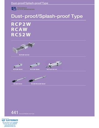
  • 1. Dust-proof/Splash-proof Type Dust-proof/Splash-proof Type RCP2W RCAW RCS2W RRCCPP22WW-RRAA1100CC RCP2W-SA16C RCP2W-RA4C RCP2W-RA6C RCAW-RA3C RCAW/RCS2W-RA4C 441 Dust-proof/Splash-proof Type Sold & Serviced By: ELECTROMATE Toll Free Phone (877) SERVO98 Toll Free Fax (877) SERV099 www.electromate.com sales@electromate.com
  • 2. RCP2W series Pulse Motor Type RCAW series 24V Servo Motor Type RCS2W series 200V Servo Motor Type Dust-proof/Splash-proof Type Slider Type Coupled 158mm width RCP2W-SA16C Rod Type Coupled 45mm width RCP2W-RA4C 64mm width RCP2W-RA6C High-thrust Type 100mm width RCP2W-RA10C Gripper Type Mini Slider Type 42mm width RCP2W-GRSS Mini Lever type 42mm width RCP2W-GRLS Rod Type Coupled ø32mm RCAW-RA3C Built-in ø32mm RCAW-RA3D Motor Side-mounted ø32mm RCAW-RA3R Rod Type Coupled ø37mm RCAW-RA4C Built-in ø37mm RCAW-RA4D Motor Side-mounted ø37mm RCAW-RA4R Rod Type Coupled ø37mm RCS2W-RA4C Built-in ø37mm RCS2W-RA4D Motor Side-mounted ø37mm RCS2W-RA4R 443 445 447 449 451 453 455 457 459 Dust-proof/Splash-proof Type 442 Slider Type Mini Standard Controllers Integrated Rod Type Mini Standard Controllers Integrated Table/Arm /Flat Type Mini Standard Gripper/ Rotary Type Linear Servo Type Cleanroom Type Splash-Proof Controllers PMEC /AMEC PSEP /ASEP ROBO NET ERC2 PCON ACON SCON PSEL ASEL SSEL XSEL Pulse Motor Servo Motor (24V) Servo Motor (200V) Linear Servo Motor Sold & Serviced By: ELECTROMATE Toll Free Phone (877) SERVO98 Toll Free Fax (877) SERV099 www.electromate.com sales@electromate.com
  • 3. RCP2W ROBO Cylinder RCP2W-SA16C ROBO Cylinder Water-proof Slider Type 158mm Width Pulse Motor Coupled ■ Configuration: RCP2W SA16C I 86P P2 Series Type Encoder Motor Lead Stroke Compatible Controllers Cable Length Option * See page Pre-35 for explanation of each code that makes up the configuration name. O I N 50 100 150 200 250 300 350 400 450 500 550 600 4mm lead Type Cable Symbol Standard Price Standard Special Lengths Robot Cable P (1m) S (3m) M (5m) X06 (6m) ~ X10 (10m) X11 (11m) ~ X15 (15m) X16 (16m) ~ X20 (20m) R01 (1m) ~ R03 (3m) R04 (4m) ~ R05 (5m) R06 (6m) ~ R10 (10m) R11 (11m) ~ R15 (15m) R16 (16m) ~ R20 (20m) − − − − − − − − − − − * See page A-39 for cables for maintenance. P. A-5 Technical References Max. Load Capacity (Note 1) Note ■ Speed vs. Load Capacity Due to the characteristics of the Pulse motor, the RCP2 series' load capacity decreases at high speeds. In the table below, check if your desired speed and load capacity are supported. Speed (mm/sec) 40 35 30 25 20 15 10 5 0 0 25 50 75 100 125 150 175 200 Load Capacity (kg) 8mm lead 1 Stroke List 2 Cable List 3 Option List Actuator Specifications Wi thout cover Wi th cover Name Option Code See Page Standard Price CO NM → 444 → A-33 With cover Reversed-home − − (Unit: mm/s) Actuator Specifications ■ Lead and Load Capacity (Note 1) Please note that the maximum load capacity decreases as the speed increases. ■ Stroke and Maximum Speed Stroke Lead 50~600 (50mm increments) 180 133 8 4 Legend 1 Stroke 2 Cable length 3 Options Lead (mm) 8 4 Horizontal (kg) ~25 ~35 Vertical (kg) Model Not Allowed Stroke (mm) 50~600 (50mm increments) − − − − − − − − − − − − − − − − − − − − − − − − Item Descr ipt ion Ball screw ø12mm C10 grade ±0.08mm 0.1 mm or less ø20 Non-lubricated Linear Sliding Guide 20.0N・m Ma direction 200mm or less IP67 0~40°C, 85%RH or less (Non-condensing) Drive System Positioning Repeatability Lost Motion Guide Allowable Static Load Moment Overhang Load Length Protection Structure Ambient Operating Temp./Humidity A dynamic moment isn't applicable for the SA16C for structural reasons. When an object is to be mounted on the slider, please fix it in a manner so that no moment load is applied in the direction Mb or Mc, and so that the load is distributed evenly. RCP2W-SA16C-I-86P-8- 1 -P2- 2 - 3 RCP2W-SA16C-I-86P-4- 1 -P2- 2 - 3 P T Notes on Selection (1) The actuator is limited to being installed horizontally. Please note that it can't be used when installed in a wrong direction (transverse, vertical or reverse). (The same goes for storage.) (2) When the stroke increases, the maximum speed will drop to prevent the ball screw from reaching the critical rotational speed. Use the actuator specification table below to check the maximum speed at the stroke you desire. (3) Since the RCP2 series use a pulse motor, the load capacity decreases at high speeds. Check in the Speed vs. Load Capacity graph to see if your desired speed and load capacity are supported. (4) The load capacity is based on operation at an acceleration of 0.2G. 0.2G is the upper limit for the acceleration. (5) The cable joint connector is not splash-proof; secure it in a place that is not prone to water spills. Stroke (mm) Standard Price 86P: Pulse motor 56 □ High Output I: Incremental Type N : None P : 1m S : 3m M : 5m X □□ : Custom Length R □□ : Robot Cable CO : With Cover NM : Reversed-home 8 : 8mm 4 : 4mm 50 : 50mm P2: PCON-CF 〜 600 : 600mm (50mm pitch increments) 443 RCP2W-SA16C Slider Type Mini Standard Controllers Integrated Rod Type Mini Standard Controllers Integrated Table/Arm /Flat Type Mini Standard Gripper/ Rotary Type Linear Servo Type Cleanroom Type Splash-Proof Controllers PMEC /AMEC PSEP /ASEP ROBO NET ERC2 PCON ACON SCON PSEL ASEL SSEL XSEL Pulse Motor Servo Motor (24V) Servo Motor (200V) Linear Servo Motor Sold & Serviced By: ELECTROMATE Toll Free Phone (877) SERVO98 Toll Free Fax (877) SERV099 www.electromate.com sales@electromate.com
  • 4. [No Cover] [With Cover] (Optional) 15 130 20 20 15 RCP2W ROBO Cylinder 155 ø90 (2m) 90 A B L 65 65 4-9 drilled, ø14 counterbore, depth 8.5 2-ø8H7 depth 10 S (Stroke) Home 53 25 125 30 5 130 4-M8 depth 20 105 80 25 52 115 100 158 4 Cable joint connector*1 Actuator cable*3 ME SE ME*2 Base plate Slider Slider rod Base plate Guide rod Motor cover 15 130 20 20 15 ø90 155 90 A B L 4-9 drilled, ø14 deep 65 65 counterbore, depth 8.5 2-ø8H10 depth 10 S (Stroke) 78 125 30 5 130 4-M8 depth 20 105 80 77 4 115 101.5 166 ME SE Home ME 4.3±0.2 7.3±0.2 8 6.5 2 A Details of A For Special Orders P. A-9 Dimensions Stroke 50 100 150 200 250 300 350 400 450 500 550 600 490 335 305 50 9 10.5 590 435 405 150 9.9 11.8 690 535 505 250 10.9 13.2 790 635 605 350 11.8 14.6 890 735 705 450 12.7 15.9 990 835 805 550 13.7 17.3 540 385 355 100 9.4 11.1 640 485 455 200 10.4 12.5 740 585 555 300 11.3 13.8 840 685 655 400 12.3 15.3 940 785 755 500 13.2 16.6 1040 885 855 600 15.1 18.9 ■ Dimensions/Weight by Stroke ※ For the reverse-home model, the dimensions (distance to home) on the motor-side and that on the opposite side are flipped. *1 A motor-encoder cable is connected here. Please note that motor cable is the same as the one in the RCP2 series, but that the encoder cable is a dedicated type. The cable joint connector is not splash-proof; therefore, please secure it in a place that is not prone to water spills. *2 When homing, the slider moves to the ME; therefore, please watch for any interference with the surrounding objects. ME: Mechanical end SE: Stroke end *3 The actuator cable is not a robot cable (flex resistant cable); therefore, please don't use it for movable parts such as in cable track. Compatible Controllers The controller for the RCP2W-SA16C type is a dedicated controller. Name External View Model Description Max. Positioning Points Input Voltage Power Supply Capacity Standard Price See Page Positioner Type Positioning possible for up to 512 points 512 points DC24V L A B S Weight without cover (kg) Weight with cover (kg) PCON-CF-86PI-NP-2-0 6A max. − → P525 Note: Please note that the encoder cable is a dedicated CF-type cable that is different from the PCON-C/CG/CY/PL/PO/SE controllers. RCP2W-SA16C 444 Slider Type Mini Standard Controllers Integrated Rod Type Mini Standard Controllers Integrated Table/Arm /Flat Type Mini Standard Gripper/ Rotary Type Linear Servo Type Cleanroom Type Splash-Proof Controllers PMEC /AMEC PSEP /ASEP ROBO NET ERC2 PCON ACON SCON PSEL ASEL SSEL XSEL Pulse Motor Servo Motor (24V) Servo Motor (200V) Linear Servo Motor Sold & Serviced By: ELECTROMATE Toll Free Phone (877) SERVO98 Toll Free Fax (877) SERV099 www.electromate.com sales@electromate.com
  • 5. RCP2W ROBO Cylinder RCP2W-RA4C ROBO Cylinder Splash-proof Rod Type 45mm Width Pulse Motor Coupled ■ Speed vs. Load Capacity 300 400 500 600 700 70 60 50 40 30 20 21 18 15 12 9 6 19 * See page Pre-35 for explanation of each code that makes up the configuration name. O I N Actuator Specifications P. A-5 Technical References Model Stroke Legend 1 Stroke 2 Compatible controller 3 Cable length 4 Options Max. Load Capacity (Note 1) Maximum Push 1 Stroke List 3 Cable List Type Cable Symbol Standard Price Standard Item Descr ipt ion Ball screw ø8mm C10 grade ±0.02mm 0.1 mm or less ø22mm ±1.5 degrees IP65 0~40°C, 85%RH or less (Non-condensing) Drive System Positioning Repeatability Lost Motion Rod diameter Rod non-rotational accuracy Protection Structure Ambient Operating Temp./Humidity Due to the characteristics of the Pulse motor, the RCP2 series' load capacity decreases at high speeds. In the table below, check if your desired speed and load capacity are supported. 0 0 100 200 Speed (mm/sec) 10 Horizontal 1L0emadm 1 l0ead 2.5mm lead 5mm lead 25 5 Load Capacity (kg) 00 50 100 150 200 250 300 350 Speed (mm/sec) 3 Vertical Lead 10 Lead 2.5 5mm lead 10mm lead 2.5mm lead 4.5 2.5 2.5 2 Load Capacity (kg) Special Lengths Robot Cable P (1m) S (3m) M (5m) X06 (6m ) ~ X10 (10m) X11 (11m) ~ X15 (15m) X16 (16m) ~ X20 (20m) R01 (1m) ~ R03 (3m) R04 (4m) ~ R05 (5m) R06 (6m) ~ R10 (10m) R11 (11m) ~ R15 (15m) R16 (16m) ~ R20 (20m) − − − − − − − − − − − * See page A-39 for cables for maintenance. 4 Option List Actuator Specifications ■ Stroke and Maximum Speed Stroke Lead 50~200 (50mm increments) 450 〈250〉 190 125 〈115〉 250 450 〈250〉 190 115 300 350 〈250〉 175 85 10 5 2.5 − − − − − − 50 100 150 200 250 300 Name Option Code See Page Standard Price B FL FT NM → A-25 → A-27 → A-29 → A-33 − − − − Brake-Equipped With Flange With Foot bracket Reversed-home (Unit: mm/s) ■ Lead and Load Capacity (Note 1) Please note that the maximum load capacity decreases as the speed increases. Lead (mm) Horizontal ( k g ) Vertical (kg) Force (N) (Note 2) (mm) RCP2W-RA4C-I-42P-10- 1 - 2 - 3 - 4 RCP2W-RA4C-I-42P-5- 1 - 2 - 3 - 4 RCP2W-RA4C-I-42P-2.5- 1 - 2 - 3 - 4 10 5 2.5 ~25 40 40 ~4.5 ~12 ~19 150 284 358 50~300 (50mm increments) (Note 2) See page A-69 for push force graph. * The value inside < > applies to vertical setting. P T Notes on Selection (1) When the stroke increases, the maximum speed will drop to prevent the ball screw from reaching the critical rotational speed. Use the actuator specification table below to check the maximum speed at the stroke you desire. (2) Since the RCP2 series use a pulse motor, the load capacity decreases at high speeds. Check in the Speed vs. Load Capacity graph on the above right to see if your desired speed and load capacity are supported. (3) The load capacity is based on operation at an acceleration of 0.2G. 0.2G is the upper limit for the acceleration. (4) The cable joint connector is not splash-proof; secure it in a place that is not prone to water spills. Stroke (mm) Standard Price 42P: Pulse motor 42 □ size I: Incremental Type * The simple absolute encoder is also considered type "I". N : None P : 1m S : 3m M : 5m X □□ : Custom R □□ : Robot Cable B : Brake-Equipped FL : With Flange FT : With Foot bracket NM : Reversed-home 10 : 10mm 5 : 5mm 2.5 : 2.5mm ■ Configuration: RCP2W RA4C I 42P Series Type Encoder Motor Lead Stroke Compatible Controllers Cable Length Option P1 : PCON RPCON PSEL P3 : PMEC PSEP 50: 50mm 〜 300: 300mm (50mm pitch increments) 445 RCP2W-RA4C Slider Type Mini Standard Controllers Integrated Rod Type Mini Standard Controllers Integrated Table/Arm /Flat Type Mini Standard Gripper/ Rotary Type Linear Servo Type Cleanroom Type Splash-Proof Controllers PMEC /AMEC PSEP /ASEP ROBO NET ERC2 PCON ACON SCON PSEL ASEL SSEL XSEL Pulse Motor Servo Motor (24V) Servo Motor (200V) Linear Servo Motor Sold & Serviced By: ELECTROMATE Toll Free Phone (877) SERVO98 Toll Free Fax (877) SERV099 www.electromate.com sales@electromate.com
  • 6. RCP2W ROBO Cylinder Cable joint connector *2 Actuator cable*5 7 Square nut insertion inlet * M10X 1.25 Secure at least 100 Intake port*1 (360 deg rotatable) Please don't apply an external force coming from a direction other than that of the rod's advance. The rotation stopper may break if a force coming from right angle or rotating direction is applied to the rod. 7.5 (width across flats) 4-M8 depth 12 Home A Sec Dimensions of Supplied Nut for Rod Tip Effective T-slot range*4 With Brake Note: Details of A Section Brake unit Rod diameter ø22 24.3 Dimensions of Supplied Square Nut for T-slot (4 nuts provided) Dimensions * Adding a brake increases overall length by 58mm and its weight by 0.4kg. 2 Compatible Controllers The RCP2W series actuators can operate with the controllers below. Select the controller according to your usage. For Special Orders P. A-9 Stroke 50 100 150 200 250 300 ℓ L Weight (kg) 132.5 223 1.9 182.5 273 2.1 232.5 323 2.2 282.5 373 2.5 332.5 423 2.9 382.5 473 3.1 ■ Dimensions/Weight by Stroke * 1. Intake/exhaust port is the air exhaust tube in the main body. Insert OD ø6 mm tube and use it extended to a place that is not prone to water spills or intake. * 2. Connect motor encoder cable . See page A-39 for details on cables. The cable joint connector is not splash-proof; therefore, please secure it in a place that is not prone to water spills. * 3. When homing, the rod moves to the ME; therefore, please watch for any interference with the surrounding objects. ME:Mechanical End SE:Stroke end The dimensions enclosed in "( )" are reference dimensions. * 4. Please note that there is no T-slot in the bottom of brake unit. * 5. The actuator cable is not a robot cable (flex resistant cable); therefore, please don't use it for movable parts such as cable track. Name External View Model Description Max. Positioning Points Input Voltage Power Supply Capacity Standard Price See Page Solenoid Valve Type PMEC-C-42PI-NP-2- 1 Easy-to-use controller, even for beginners. 3 points AC100V AC200V See P481 − → P477 PSEP-C-42PI-NP-2-0 Operable with same signal as solenoid valve. Supports both single and double solenoid types. No homing necessary with simple absolute type. DC24V 2A max. − → P487 Splash-Proof Solenoid Valve Type PSEP-CW-42PI-NP-2-0 − Positioner Type PCON-C-42PI-NP-2-0 Positioning possible for up to 512 points 512 points − → P525 Safety Category Compliant Positioner Type PCON-CG-42PI-NP-2-0 − Pulse Train Input Type (Differential Line Driver) PCON-PL-42PI-NP-2-0 Differential line driver support Pulse Train Input Type (−) − Pulse Train Input Type (Open Collector) PCON-PO-42PI-NP-2-0 Open Collector Pulse Train Input Type − Serial PCON-SE-42PI-N-0-0 Dedicated to serial Communication Type communication 64 points − Field Network Type RPCON-42P Dedicated to field network 768 points − → P503 Program Control Type PSEL-C-1-42PI-NP-2-0 Programmed operation is possible Can operate up to 2 axes 1500 points − → P557 * This is for the single-axis PSEL. *1 is a placeholder for the power supply voltage (1:100V/2:100~240V). RCP2W-RA4C 446 Slider Type Mini Standard Controllers Integrated Rod Type Mini Standard Controllers Integrated Table/Arm /Flat Type Mini Standard Gripper/ Rotary Type Linear Servo Type Cleanroom Type Splash-Proof Controllers PMEC /AMEC PSEP /ASEP ROBO NET ERC2 PCON ACON SCON PSEL ASEL SSEL XSEL Pulse Motor Servo Motor (24V) Servo Motor (200V) Linear Servo Motor Sold & Serviced By: ELECTROMATE Toll Free Phone (877) SERVO98 Toll Free Fax (877) SERV099 www.electromate.com sales@electromate.com
  • 7. RCP2W ROBO Cylinder RCP2W-RA6C ROBO Cylinder Splash-proof Rod Type 64mm Width Pulse Motor Coupled ■ Speed vs. Load Capacity 300 400 500 600 700 70 60 50 40 30 20 4mm lead 35 30 25 20 15 10 * See page Pre-35 for explanation of each code that makes up the configuration name. O I N Actuator Specifications P. A-5 Technical References Model Stroke Legend 1 Stroke 2 Compatible controller 3 Cable length 4 Options Max. Load Capacity (Note 1) Maximum Push ■ Stroke and Maximum Speed 1 Stroke List 3 Cable List Type Cable Symbol Standard Price Standard Item Descr ipt ion Ball screw ø12mm C10 grade ±0.02mm 0.1 mm or less ø30mm ±1.0 degrees IP65 0~40°C, 85%RH or less (Non-condensing) Drive System Positioning Repeatability Lost Motion Rod diameter Rod non-rotational accuracy Protection Structure Ambient Operating Temp./Humidity Due to the characteristics of the Pulse motor, the RCP2 series' load capacity decreases at high speeds. In the table below, check if your desired speed and load capacity are supported. 0 0 100 200 Speed (mm/sec) 10 Horizontal 16mm lead 8mm lead 16mm lead 554mm Load Capacity (kg) 00 50 100 150 200 250 300 350 Speed (mm/sec) 5 Vertical 8mm lead 16mm lead 4mm lead 2 1 26 17.5 Load Capacity (kg) Special Lengths Robot Cable P (1m) S (3m) M (5m) X06 (6m) ~ X10 (10m) X11 (11m) ~ X15 (15m) X16 (16m) ~ X20 (20m) R01 (1m) ~ R03 (3m) R04 (4m) ~ R05 (5m) R06 (6m) ~ R10 (10m) R11 (11m) ~ R15 (15m) R16 (16m) ~ R20 (20m) − − − − − − − − − − − * See page A-39 for cables for maintenance. − − − − − − 50 100 150 200 250 300 4 Option List Actuator Specifications Name Opt ion Code See Page Standard Pr ice B FL FT NM → A-25 → A-27 → A-29 → A-33 − − − − Brake-Equipped With Flange With Foot bracket Reversed-home (Unit: mm/s) ■ Lead and Load Capacity (Note 1) Please note that the maximum load capacity decreases as the speed increases. Lead (mm) Horizontal( k g ) Vertical(kg) Force (N) (Note 2) (mm) RCP2W-RA6C-I-56P-16- 1 - 2 - 3 - 4 RCP2W-RA6C-I-56P-8- 1 - 2 - 3 - 4 RCP2W-RA6C-I-56P-4- 1 - 2 - 3 - 4 16 8 4 ~40 50 55 ~5 ~17.5 ~26 240 470 800 50~300 (50mm increments) Stroke Lead 50~300 (50mm increments) 320〈265〉 200 100 16 8 4 (Note 2) See page A-69 for push force graph. * The value inside < > applies to vertical setting. P T Notes on Selection (1) When the stroke increases, the maximum speed will drop to prevent the ball screw from reaching the critical rotational speed. Use the actuator specification table below to check the maximum speed at the stroke you desire. (2) Since the RCP2 series use the pulse motor, the load capacity decreases at high speeds. Check in the Speed vs. Load Capacity graph on the above right to see if your desired speed and load capacity are supported. (3) The load capacity is based on operation at an acceleration of 0.2G. 0.2G is the upper limit for the acceleration. (4) The cable joint connector is not splash-proof; secure it in a place that is not prone to water spills. Stroke (mm) Standard Price 56P: Pulse motor 56 □ size I: Incremental Type * The simple absolute encoder is also considered type "I". N : None P : 1m S : 3m M : 5m X □□ : Custom Length R □□ : Robot Cable B : Brake-Equipped FL : With Flange FT : With Foot bracket NM : Reversed-home 16 : 16mm 8 : 8mm 4 : 4mm ■ Configuration: RCP2W RA6C I 56P Series Type Encoder Motor Lead Stroke Compatible Controllers Cable Length Option P1 : PCON RPCON PSEL P3 : PMEC PSEP 50: 50mm 〜 300: 300mm (50mm pitch increments) 447 RCP2W-RA6C Slider Type Mini Standard Controllers Integrated Rod Type Mini Standard Controllers Integrated Table/Arm /Flat Type Mini Standard Gripper/ Rotary Type Linear Servo Type Cleanroom Type Splash-Proof Controllers PMEC /AMEC PSEP /ASEP ROBO NET ERC2 PCON ACON SCON PSEL ASEL SSEL XSEL Pulse Motor Servo Motor (24V) Servo Motor (200V) Linear Servo Motor Sold & Serviced By: ELECTROMATE Toll Free Phone (877) SERVO98 Toll Free Fax (877) SERV099 www.electromate.com sales@electromate.com
  • 8. RCP2W ROBO Cylinder Actuator cable*5 Intake port*1 (360 deg rotatable) Square nut insertion inlet Dimensions of Supplied Nut for Rod Tip 4-M8 depth 15 A Sec. Please don't apply an external force coming from a direction other than that of the rod's advance. The rotation stopper may break if a force coming from right angle or rotating direction is applied to the rod. Dimensions of Supplied Square Nut for T-slot (4 nuts provided) Home ME *3 Note: Details of A Section Hex Socket Bolt: 4-M5X20 Effective T-slot range*4 With Brake Cable joint connector *2) Secure at least 100 9.5 (width across flats) Brake unit Rod diameter ø30 Dimensions * Adding a brake increases overall length by 72.5mm and its weight by 0.9kg. 2 Compatible Controllers The RCP2W series actuators can operate with the controllers below. Select the controller according to your usage. For Special Orders P. A-9 *1. Intake/exhaust port is the air exhaust tube in the main body. Insert OD ø6 mm tube and use it extended to a place that is not prone to water spills or intake. *2. Connect motor encoder cable . See page A-39 for details on cables. The cable joint connector is not splash-proof; therefore, please secure it in a place that is not prone to water spills. *3. When homing, the rod moves to the ME; therefore, please watch for any interference with the surrounding objects. ME: Mechanical End SE: Stroke end The dimensions enclosed in "( )" are reference dimensions. *4. Please note that there is no T-slot in the bottom of brake unit. *5. The actuator cable is not a robot cable (flex resistant cable); therefore, please don't use it for movable parts such as cable track. Stroke 50 100 150 200 250 300 ℓ L Weight (kg) 150 266 3.5 200 316 4.0 250 366 4.5 300 416 5.0 350 466 5.5 400 516 6.0 ■ Dimensions/Weight by Stroke Name External View Model Description Max. Positioning Points Input Voltage Power Supply Capacity Standard Price See Page Solenoid Valve Type PMEC-C-56PI-NP-2-1 Easy-to-use controller, even for beginners. 3 points AC100V AC200V See P481 − → P477 PSEP-C-56PI-NP-2-0 Operable with same signal as solenoid valve. Supports both single and double solenoid types. No homing necessary with simple absolute type. DC24V 2A max. − → P487 Splash-Proof Solenoid ValveType PSEP-CW-56PI-NP-2-0 − Positioner Type PCON-C-56PI-NP-2-0 Positioning possible for up to 512 points 512 points − → P525 Safety Category Compliant Positioner Type PCON-CG-56PI-NP-2-0 − Pulse Train Input ype (Differential Line Driver) PCON-PL-56PI-NP-2-0 Differential line driver support Pulse Train Input Type (−) − Pulse Train Input Type (Open Collector) PCON-PO-56PI-NP-2-0 Open Collector Pulse Train Input Type − Serial Dedicated to serial Communication Type PCON-SE-56PI-N-0-0 communication 64 points − Field Network Type RPCON-56P Dedicated to field network 768 points − → P503 Program Control Type PSEL-C-1-56PI-NP-2-0 Programmed operation is possible Can operate up to 2 axes 1500 points − → P557 * This is for the single-axis PSEL. *1 is a placeholder for the power supply voltage (1:100V / 2:100~240V) RCP2W-RA6C 448 Slider Type Mini Standard Controllers Integrated Rod Type Mini Standard Controllers Integrated Table/Arm /Flat Type Mini Standard Gripper/ Rotary Type Linear Servo Type Cleanroom Type Splash-Proof Controllers PMEC /AMEC PSEP /ASEP ROBO NET ERC2 PCON ACON SCON PSEL ASEL SSEL XSEL Pulse Motor Servo Motor (24V) Servo Motor (200V) Linear Servo Motor Sold & Serviced By: ELECTROMATE Toll Free Phone (877) SERVO98 Toll Free Fax (877) SERV099 www.electromate.com sales@electromate.com
  • 9. RCP2W ROBO Cylinder RCP2W-RA10C ROBO Cylinder High-thrust Dust-proof Rod Type 100mm Width Pulse Motor ■ Configuration: RCP2W RA10C I 86P P2 O I N P T Notes on Selection Series Type Encoder Motor Lead Stroke Compatible Controllers Cable Length Option ■ Speed vs. Load Capacity 1000 100 Horizontal 10mm lead 2.5mm lead 5mm lead 300 150 80 Vertical 10mm lead 1000 100 10 150 80 10 Actuator Specifications 86P: Pulse motor 86 □ size P. A-5 Technical References I: Incremental Type Model Stroke Legend 1 Stroke 2 Cable length 3 Options Max. Load Capacity (Note 1) Maximum Push 1 Stroke List 2 Cable List Type Cable Symbol Standard Price Standard Item Descr ipt ion 6 5mm lead 3 Ball screw C10 grade ±0.02mm 0.1 mm or less ø40mm ±1.0 degrees IP54 0~40°C, 85%RH or less (Non-condensing) Drive System Positioning Repeatability Lost Motion Rod diameter Rod non-rotational accuracy Protection Structure Ambient Operating Temp./Humidity Due to the characteristics of the Pulse motor, the RCP2 series' load capacity decreases at high speeds. In the table below, check if your desired speed and load capacity are supported. Speed (mm/s) 10 15 0 50 100 150 200 250 300 Load Capacity (kg) Speed (mm/s) 2.5mm lead 1 0 50 100 150 200 Load Capacity (kg) (1) Minimum speed is set for each lead. (Lead 10: 10mm/s, Lead 5: 5mm/s, Lead 2.5: 1mm/s) Please note that vibration etc. may occur when operated at minimum speed. (2) Since the RCP2 series use a pulse motor, the load capacity decreases at high speeds. Check the Speed vs. Load Capacity on the right hand graph to see if your desired speed and load capacity are supported. (3) The load capacity is based on operation at lead 10: 0.04G, lead 5: 0.02G and lead 2.5: 0.01G. These values are the upper limits for the acceleration. Also, this is when the load capacity is attached to the external guide. The rotation stopper may break if an external force coming from a direction other than that of rod's advance is applied. (4) The cable joint connector is not splash-proof; secure it in a place that is not prone to water spills. Special Lengths Robot Cable P (1m) S (3m) M (5m) X06 (6m) ~ X10 (10m) X11 (11m) ~ X15 (15m) X16 (16m) ~ X20 (20m) R01 (1m) ~ R03 (3m) R04 (4m) ~ R05 (5m) R06 (6m) ~ R10 (10m) R11 (11m) ~ R15 (15m) R16 (16m) ~ R20 (20m) − − − − − − − − − − − * See page A-39 for cables for maintenance. 3 Option List Actuator Specifications ■ Stroke and Maximum Speed − − − − − − 50 100 150 200 250 300 (Unit: mm/s) ■ Lead and Load Capacity (Note 1) Please note that the maximum load capacity decreases as the speed increases. Lead (mm) Horizontal(kg) Vertical(kg) Force (N) (Note 2) (mm) RCP2W-RA10C-I-86P-10- 1 -P2- 2 - 3 RCP2W-RA10C-I-86P-5- 1 -P2- 2 - 3 RCP2W-RA10C-I-86P-2.5- 1 -P2- 2 - 3 10 5 2.5 ~80 150 300 ~80 ~100 ~150 1500 3000 6000 50~300 (50mm increments) Stroke Lead 50~300 (50mm increments) 250〈167〉 125 63 10 5 2.5 Name Option Code See Page Standard Price A1~A3 B FL FT → A-25 → A-25 → A-27 → A-29 Connector cable outlet direction changed Brake Flange Foot bracket − − − − (Note 2) See page A-70 for push force graph. * The value inside < > applies to vertical setting. Stroke (mm) Standard Price Coupled * See page Pre-35 for explanation of each code that makes up the configuration name. N : None P : 1m S : 3m M : 5m X □□ : Custom Length R □□ : Robot Cable A1~A3 : Connector cable Cable outlet direction changed B : Brake-Equipped FL : With Flange FT : With Foot bracket 10 : 10mm 5 : 5mm 2.5 : 2.5mm 50: 50mm P2 : PCON-CF 〜 300: 300mm (50mm pitch increments) 449 RCP2W-RA10C Slider Type Mini Standard Controllers Integrated Rod Type Mini Standard Controllers Integrated Table/Arm /Flat Type Mini Standard Gripper/ Rotary Type Linear Servo Type Cleanroom Type Splash-Proof Controllers PMEC /AMEC PSEP /ASEP ROBO NET ERC2 PCON ACON SCON PSEL ASEL SSEL XSEL Pulse Motor Servo Motor (24V) Servo Motor (200V) Linear Servo Motor Sold & Serviced By: ELECTROMATE Toll Free Phone (877) SERVO98 Toll Free Fax (877) SERV099 www.electromate.com sales@electromate.com
  • 10. RCP2W ROBO Cylinder Dimensions Supplied Nut Cable joint 52.5 45.5 117.5 (1) Dimensions of the Brake Section 37 ST+115 13.5 (wi d th across flats)*3 37 (effective screw thread range) 26 diagonal L 117.5 (2m) 52.5 32 diagonal 80 95 M22×1.5 37 13 4-M10 depth 18 100 5 100 ME SE Home ME*2 (1) ø70h10 120 4-M10 through 40 M22×1.5 5 2 7.5 Intake/exhaust port*4 5 Effective ST (81) 40 20 ST+60 80 connector*1 Actuator cable *5 The joint can rotate 360° Dimensions For Special Orders P. A-9 *1. A motor-encoder cable is connected here. Please note that motor cable is the same as the one in the RCP2 series, but that the encoder cable is a dedicated type. See page A-39 for details on cables. The cable joint connector is not splash-proof; therefore, please secure it in a place that is not prone to water spills. *2. When homing, the rod moves to the ME; therefore, please watch for any interference with the surrounding objects. ME: Mechanical end SE: Stroke end The dimensions enclosed in "( )" are reference dimensions. *3. The direction of across-flats will vary depending on the product. *4. Intake/exhaust port is the air exhaust tube in the main body. *5. The actuator cable is not a robot cable (flex resistant cable); therefore, please don't use it for movable parts such as cable track. * Adding a brake increases overall length by 45.5mm and its weight by 1.5kg. Stroke 50 100 150 200 250 300 L Weight (kg) 372 9 422 9.5 472 10 522 10.5 572 11 622 11.5 ■ Dimensions/Weight by Stroke * Please note that reversed home position is unavailable for the RA10C type for structural reasons. Compatible Controllers The controller for the RCP2W-RA10C type is a dedicated controller. Name External View Model Description Max. Positioning Points Input Voltage Power Supply Capacity Standard Price See Page Positioner Type Positioning possible for up to 512 points PCON-CF-86PI-NP-2-0 512 points DC24V 6A max. − → P525 Note: Please note that the encoder cable is a dedicated CF-type cable that is different from the PCON-C/CG/CY/PL/PO/SE controllers. RCP2W-RA10C 450 Slider Type Mini Standard Controllers Integrated Rod Type Mini Standard Controllers Integrated Table/Arm /Flat Type Mini Standard Gripper/ Rotary Type Linear Servo Type Cleanroom Type Splash-Proof Controllers PMEC /AMEC PSEP /ASEP ROBO NET ERC2 PCON ACON SCON PSEL ASEL SSEL XSEL Pulse Motor Servo Motor (24V) Servo Motor (200V) Linear Servo Motor Sold & Serviced By: ELECTROMATE Toll Free Phone (877) SERVO98 Toll Free Fax (877) SERV099 www.electromate.com sales@electromate.com
  • 11. RCP2W ROBO Cylinder RCP2W-GRSS ROBO Cylinder 2-Finger Gripper Mini Slider Type 42mm Width Pulse Motor ■ Configuration: RCP2W GRSS I 20P 30 8 O I N P T Notes on Selection Series Type Encoder Motor Lead Stroke Compatible Controllers Cable Length Option 20P: Pulse motor 20 □ size I: Incremental Type * The simple absolute encoder is also considered type "I". (1) The max. open/close speed represents one side operating speed. (2) The max. grip force will be the sum of the two fingers grip force when the distance for grip point and over hang is 0. The actual work part weight which can be transported depends on the friction constant between finger and work material, and the form; typically it is 1/10~1/20 or less than gripping force. (See page A-74 for details.) (3) The rated acceleration at transportation is 0.3G. (4) Please note that the product has no splash-proof function. Model Max. Grip Force Stroke (N) Legend 1 Compatible controller 2 Cable length 3 Options (Unit: mm/s) Name Option Code See Page Standard Price NM FB SB → A-33 → 26 → 36 Reversed-home Flange Bracket Shaft Bracket − − − ■ Grip Force Arrangement Through push operation the grip force (push force) can be arranged freely within the range of 20%-70% of current limit value of the controller. * Grip force noted in the figure below is the sum of the grip force of two fingers. 16 14 12 10 8 6 4 0 0 10 20 30 40 50 60 70 Current Limit (% ratio) 2 Gripping force (N) Stroke List 2 Cable List Type Cable Symbol Standard Price Standard (Robot Cables) 3 Option List Actuator Specifications Item Descr ipt ion Worm gear + Helical gear + Helical rack ±0.01mm 0.2 mm or less for one side (stressed by spring on the side which is opened always) 0.05mm or less one side Linear Guide Ma:0.5N・m Mb:0.5N・m Mc:1.5N・m 0.2kg 0~40°C, 85%RH or less (Non-condensing) Drive System Positioning Repeatability Backlash Lost Motion Guide Statically Allowable Load Moment Weight Ambient Operating Temp./Humidity Actuator Specifications ■ Lead and Load Capacity ■ Stroke and Maximum Open/Close Speed Deceleration ratio 30 14 (mm) RCP2W-GRSS-I-20P-30-8- 1 - 2 - 3 8 (One side 4) Stroke Decele-ration ratio 8 (mm) 30 78 8 − Technical References P. A-5 * Please note when gripping (pushing) is performed the speed will be fixed at 5 mm/s. Stroke (mm) Standard Price Special Lengths P (1m) S (3m) M (5m) X06 (6m) ~ X10 (10m) X11 (11m) ~ X15 (15m) X16 (16m) ~ X20 (20m) − − − − − − * The standard cable is the motor-encoder integrated robot cable. * See page A-39 for cables for maintenance. * See page Pre-35 for explanation of each code that makes up the configuration name. N : None P : 1m S : 3m M : 5m X □□ : Custom Length NM : Reversed-home FB : Flange Bracket SB : Shaft Bracket 30 : Deceleration ratio 1/30 P1 : PCON RPCON PSEL P3 : PMEC PSEP 8 : 8mm (One side 4mm) 451 RCP2W-GRSS Slider Type Mini Standard Controllers Integrated Rod Type Mini Standard Controllers Integrated Table/Arm /Flat Type Mini Standard Gripper/ Rotary Type Linear Servo Type Cleanroom Type Splash-Proof Controllers PMEC /AMEC PSEP /ASEP ROBO NET ERC2 PCON ACON SCON PSEL ASEL SSEL XSEL Pulse Motor Servo Motor (24V) Servo Motor (200V) Linear Servo Motor Sold & Serviced By: ELECTROMATE Toll Free Phone (877) SERVO98 Toll Free Fax (877) SERV099 www.electromate.com sales@electromate.com
  • 12. RCP2W ROBO Cylinder Cable joint connector*1 Secure at least 100 −0.05 11+0 94 2×2-M3 (same with opposite side) MAX22 MIN14 46 17 8.5 +0.03 0 depth 3 8-M3 depth 5 (same with opposite side) 4-M3 depth 5 2−3 +0.05 0 depth 3 (same with opposite side) 34 4 4 3+0.05 0 depth 3 2-ø3 +0.03 0 depth 3 (same with opposite side) ø3 42 36 33 17 8.5 4 3+0.05 ø3 +0.03 0 depth 3 4-M3 depth 5 0 depth 3 24 30 5 ø4 61.5 9 2.5 6 57.5 35 17 For Special Order P. A-9 Dimensions * Open side of slider will be home position. *1 A motor-encoder cable is connected here. See page A-39 for details on cables. Weight (kg) 0.2 1 Compatible Controllers The RCP2W series actuators can operate with the controllers below. Select the controller according to your usage. Name External View Model Description Max. Positioning Points Input Voltage Power Supply Capacity Standard Price See Page Solenoid ValveType PMEC-C-20PI-NP-2-1 Easy-to-use controller, even for beginners. 3 points AC100V AC200V See P481 − → P477 PSEP-C-20PI-NP-2-0 Operable with same signal as solenoid valve. Supports both single and double solenoid types. No homing necessary with simple absolute type. DC24V 2A max. − → P487 Splash-Proof Solenoid Type PSEP-CW-20PI-NP-2-0 − Positioner Type PCON-C-20PI-NP-2-0 Positioning possible for up to 512 points 512 points − → P525 Safety Category Compliant Positioner Type PCON-CG-20PI-NP-2-0 − Pulse Train Input Type (Differential Line Driver) PCON-PL-20PI-NP-2-0 Differential line driver support Pulse Train Input Type (−) − Pulse Train Input Type (Open Collector) PCON-PO-20PI-NP-2-0 Open Collector Pulse Train Input Type − Type PCON-SE-20PI-N-0-0 Dedicated to serial Serial Communication communication 64 points − Field NetworkType RPCON-20P Dedicated to field network 768 points − → P503 Program Control Type PSEL-C-1-20PI-NP-2-0 Programmed operation is possible Can operate up to 2 axes 1500 points − → P557 * This is for the single-axis PSEL. * 1 is a placeholder for the power supply voltage (1:100V / 2:100~240V). CAD drawings can be downloaded from IAI website. www.intelligentactuator.com RCP2W-GRSS 452 Slider Type Mini Standard Controllers Integrated Rod Type Mini Standard Controllers Integrated Table/Arm /Flat Type Mini Standard Gripper/ Rotary Type Linear Servo Type Cleanroom Type Splash-Proof Controllers PMEC /AMEC PSEP /ASEP ROBO NET ERC2 PCON ACON SCON PSEL ASEL SSEL XSEL Pulse Motor Servo Motor (24V) Servo Motor (200V) Linear Servo Motor Sold & Serviced By: ELECTROMATE Toll Free Phone (877) SERVO98 Toll Free Fax (877) SERV099 www.electromate.com sales@electromate.com
  • 13. RCP2W ROBO Cylinder RCP2W-GRLS ROBO Cylinder 2-Finger Gripper Mini Lever Type 42mm Width Pulse Motor ■ Configuration: RCP2W GRLS I 20P 30 180 O I N P T Notes on Selection Series Type Encoder Motor Lead Stroke Compatible Controllers Cable Length Option ■ Grip Force Arrangement Through push operation the grip force (push force) can be arranged freely within the range of 20%~70% of current limit value of the controller. * Grip force noted in the figure below is the sum of the grip force of two fingers. 7 6 5 4 3 2 0 0 10 20 30 40 50 60 70 Current Limit (% ratio) 1 Gripping force (N) 20P: Pulse motor 20 □ size I: Incremental Type * The simple absolute encoder is also considered type "I". (1) The max. open/close speed represents one side operating speed. (2) The max. grip force will be the sum of the two fingers grip force when the distance for grip point and over hang is 0. The actual work part weight which can be transported depends on the friction constant between finger and work part material, and the form; typically it is 1/10 ~ 1/20 or less than gripping force. (See page A-77 for details.) (3) The rated acceleration at transportation is 0.3G. (4) Please note that the product has no splash-proof function. Model Max. Grip Force Stroke (N) Legend 1 Compatible controller 2 Cable length 3 Options (Unit: degrees/s) Stroke List 2 Cable List Type Cable Symbol Standard Price Standard (Robot Cables) Actuator Specifications Item Description Worm gear + Helical gear ±0.01mm 1 degree or less for one side (stressed by spring on the side which is opened always) 0.1 mm or less one side − − 0.2kg 0~40°C, 85%RH or less (Non-condensing) Drive System Positioning Repeatability Backlash Lost Motion Guide Statically Allowable Load Moment Weight Ambient Operating Temp./Humidity Actuator Specifications ■ Lead and Load Capacity ■ Stroke and Maximum Open/Close Speed Stroke Deceleration ratio 180 (degrees) 30 600 Technical References P. A-5 * Please note when gripping (pushing) is performed the speed will be fixed at 5 degrees/sec. Stroke (degrees) Standard Price 180 − Name Option Code See Page Standard Price NM FB SB A-33 26 36 Reversed-home Flange Bracket Shaft Bracket − − − 3 Option List Special Lengths P (1m) S (3m) M (5m) X06 (6m) ~ X10 (10m) X11 (11m) ~ X15 (15m) X16 (16m) ~ X20 (20m) − − − − − − * The standard cable is the motor-encoder integrated robot cable. * See page A-39 for cables for maintenance. Deceleration ratio 30 6.4 degrees) RCP2W-GRLS-I-20P-30-180- 1 - 2 - 3 180 (One side 90) * See page Pre-35 for explanation of each code that makes up the configuration name. N : None P : 1m S : 3m M : 5m X □□ : Custom Length NM : Reversed-home FB : Flange Bracket SB : Shaft Bracket 30 : Deceleration ratio 1/30 P1 : PCON RPCON PSEL P3 : PMEC PSEP 180 : 180 Degress (One side 90 dedress) 453 RCP2W-GRLS Slider Type Mini Standard Controllers Integrated Rod Type Mini Standard Controllers Integrated Table/Arm /Flat Type Mini Standard Gripper/ Rotary Type Linear Servo Type Cleanroom Type Splash-Proof Controllers PMEC /AMEC PSEP /ASEP ROBO NET ERC2 PCON ACON SCON PSEL ASEL SSEL XSEL Pulse Motor Servo Motor (24V) Servo Motor (200V) Linear Servo Motor Sold & Serviced By: ELECTROMATE Toll Free Phone (877) SERVO98 Toll Free Fax (877) SERV099 www.electromate.com sales@electromate.com
  • 14. CAD drawings can be downloaded from IAI website. www.intelligentactuator.com Secure at least 100 RCP2W ROBO Cylinder Cable joint connector*1 +0.03 0 +0.03 15.5 MAX 180° MIN 0° 73 9 −0.05 18 +0 34 Depth 3 4 ø4 17 8.5 4 2-3 Depth 3 (same with opposite side) 4-M3 depth 5 49 42 2-ø3 3 0 +0.05 0 +0.05 0 +0.03 0 Depth 3 (same with opposite side) ø3 Depth 3 8-M3 depth 5 (same with opposite side) 45 67.5 24 2-ø4 Depth 2.5 4-M4 through 18 9 36 9 55 35 For Special Order P. A-9 Dimensions * Open side of slider will be home position. *1 A motor-encoder cable is connected here. See page A-39 for details on cables. Weight (kg) 0.2 1 Compatible Controllers The RCP2W series actuators can operate with the controllers below. Select the controller according to your usage. Name External View Model Description Max. Positioning Points Input Voltage Power Supply Capacity Standard Price See Page Solenoid ValveType PMEC-C-20PI-NP-2-1 Easy-to-use controller, even for beginners. 3 points AC100V AC200V See P481 − → P477 PSEP-C-20PI-NP-2-0 Operable with same signal as solenoid valve. Supports both single and double solenoid types. No homing necessary with simple absolute type. DC24V 2A max. − → P487 Splash-Proof Solenoid Valve Type PSEP-CW-20PI-NP-2-0 − Positioner Type PCON-C-20PI-NP-2-0 Positioning possible for up to 512 points 512 points − → P525 Safety Category Compliant Positioner Type PCON-CG-20PI-NP-2-0 − Pulse Train Input Type (Differential Line Driver) PCON-PL-20PI-NP-2-0 Differential line driver support Pulse Train Input Type (−) − Pulse Train Input Type (Open Collector) PCON-PO-20PI-NP-2-0 Open Collector Pulse Train Input Type − Serial Communication Type PCON-SE-20PI-N-0-0 Dedicated to serial communication 64 points − Field Dedicated to field NetworkType RPCON-20P network 768 points − → P503 Program Control Type PSEL-C-1-20PI-NP-2-0 Programmed operation is possible Can operate up to 2 axes 1500 points − → P557 * This is for the single-axis PSEL. * 1 is a placeholder for the power supply voltage (1:100V / 2:100~240V). RCP2W-GRLS 454 Slider Type Mini Standard Controllers Integrated Rod Type Mini Standard Controllers Integrated Table/Arm /Flat Type Mini Standard Gripper/ Rotary Type Linear Servo Type Cleanroom Type Splash-Proof Controllers PMEC /AMEC PSEP /ASEP ROBO NET ERC2 PCON ACON SCON PSEL ASEL SSEL XSEL Pulse Motor Servo Motor (24V) Servo Motor (200V) Linear Servo Motor Sold & Serviced By: ELECTROMATE Toll Free Phone (877) SERVO98 Toll Free Fax (877) SERV099 www.electromate.com sales@electromate.com
  • 15. RCAW ROBO Cylinder RCAW-RA3C/RA3D/RA3R ROBO Cylinder Splash-proof Rod Type Actuator Specifications 10 : 10mm See Options below 5 : 5mm 2.5 : 2.5mm O I N ø32mm Diameter 24V Servo Motor Coupled/Built-in/Side-Mounted Motor Specification 20 : 20W servo motor I: Incremental Type * The simple absolute encoder is also considered type "I". ■ Lead and Load Capacity ■ Stroke and Maximum Speed Model Stroke Legend 1 Type 2 Stroke 3 Compatible controller 4 Cable length 5 Options Max. load capacity Rated Encoder & Stroke List 4 Cable List Item Type Cable Symbol Standard Price Standard Special Lengths Robot Cable P (1m) S (3m) M (5m) X06 (6m) ~ X10 (10m) X11 (11m) ~ X15 (15m) X16 (16m) ~ X20 (20m) R01 (1m) ~ R03 (3m) R04 (4m) ~ R05 (5m) R06 (6m) ~ R10 (10m) R11 (11m) ~ R15 (15m) R16 (16m) ~ R20 (20m) − − − − − − − − − − − * See page A-39 for cables for maintenance. 5 Option List − − − − − − − − − − − − 50 100 150 200 Standard Price RA3C RA3D RA3R 2 Stroke (mm) (Unit: mm/s) Motor Output (W) Lead (mm) Horizontal(kg) Vertical(kg) thrust (N) (mm) RCAW- 1 -I-20-10- 2 - 3 - 4 - 5 RCAW- 1 -I-20-5- 2 - 3 - 4 - 5 RCAW- 1 -I-20-2.5- 2 - 3 - 4 - 5 20 10 5 2.5 4 9 18 1.5 3 6.5 36.2 72.4 144.8 50~200 (50mm increments) Stroke Lead 50~200 (50mm increments) 500 250 125 10 5 2.5 Name Opt ion Code See Page Standard Pr ice B FL FT HS LA NJ NM QR RP TRF TRR → A-25 → A-27 → A-29 → A-32 → A-32 → A-34 → A-33 → A-34 → A-33 → A-38 → A-38 Brake (*1) Flange bracket Foot bracket Home confirmation sensor (*2) Power-saving Knuckle Joint Reversed-home (*2) Clevis Bracket (*3) Rear mounting plate (*3) Trunnion Bracket (Front) (*4) Trunnion Bracket (Back) (*4) − − − − − − − − − − − Actuator Specifications (*1) No brake option for RA3D. (*2) Home sensor (HS) can't be used with reversed-home (NM). (*3) Clevis bracket and rear mounting plate only available for RA3R. (*4) Trunnion bracket (rear) only available for RA3C/RA3D. P T Notes on Selection (1) When the stroke increases, the maximum speed will drop to prevent the ball screw from reaching the critical rotational speed. Use the actuator specification table below to check the maximum speed at the stroke you desire. (2) The load capacity is based on operation at an acceleration of 0.3G (0.2G for the 2.5mm-lead model). These values are the upper limits for the acceleration. (3) Please use external guide combination for horizontal load capacity; the value is for when no external force coming from a direction other than that of rod's advance is applied. (4) The cable joint connector is not splash-proof; secure it in a place that is not prone to water spills. P. A-5 Technical References Descr ipt ion Ball screw ø8mm C10 grade ±0.02mm 0.1 mm or less Material: Aluminum (white alumite treated) ø16mm ±1.0 degrees IP54 0~40°C, 85%RH or less (Non-condensing) Drive System Positioning Repeatability Lost Motion Base Rod diameter Rod non-rotational accuracy Protection Structure Ambient Operating Temp./Humidity Power-saving * See page Pre-35 for explanation of each code that makes up the configuration name. N : None P : 1m S : 3m M : 5m X □□ : Custom Length R □□ : Robot Cable ■ Configuration: RCAW I 20 Series Type Encoder Motor Lead Stroke Compatible Controllers Cable Length Option A1 : ACON RACON ASEL A3 : AMEC ASEP 50:50mm 〜 200:200mm (50mm pitch increments) RA3C: Coupled type RA3D: Built-in RA3R: Side-Mounted Motor 455 RCAW-RA3C/RA3D/RA3R Slider Type Mini Standard Controllers Integrated Rod Type Mini Standard Controllers Integrated Table/Arm /Flat Type Mini Standard Gripper/ Rotary Type Linear Servo Type Cleanroom Type Splash-Proof Controllers PMEC /AMEC PSEP /ASEP ROBO NET ERC2 PCON ACON SCON PSEL ASEL SSEL XSEL Pulse Motor Servo Motor (24V) Servo Motor (200V) Linear Servo Motor Sold & Serviced By: ELECTROMATE Toll Free Phone (877) SERVO98 Toll Free Fax (877) SERV099 www.electromate.com sales@electromate.com
  • 16. RCAW ROBO Cylinder ■ Dimensions/Weight by Stroke RCAW-RA3C/RA3D/RA3R (without brake) 200 528.9 509.9 463.4 282 282 270 144.4 144.4 144.4 200 Stroke 50 100 150 RCAW-RA3C/RA3D/RA3R (with brake) No brake-equipped model. No brake-equipped model. 124.5 No brake-equipped model. 124.5 567.9 463.4 282 270 144.4 No brake-equipped model. 144.4 1.5 1.5 1.6 85.5 66.5 85.5 Weight (kg) Secure at least 100 M8 depth 15 84.4 42.4 Bellows ME SE Home ME*2 ME SE Home ME*2 ø48.6 (15.01) 5 13 8 46 ø34 M26x1.5 7 32 M35x1.5 M8×1.25 Intake/exhaust port (can rotate by 360゚) 18 20 20 M8×1.25 (effective screw range 16) M35×1.5 (effective screw range 17.5) M26×1.5 (effective screw range 17.5) 6 11 (across flats) 32 (across flats) Nut A 32 (across flats) 40 (across flats) 3 st 3 n 14 *1 22 10 17 L ø42 ø35 ø32 38.6 56.1 n 41 12 m 9.5 Nut B Nut C Bellows 44 36.4 ø48.6 36.4 44 ø45 ø42 32 (across flats) 31 18 L ℓ 10 m 6 9.5 ø32 ø45 ø35 Nut A 6 11 (across flats) 32 (across flats) Nut A 3 st 3 n 22 38.6 56.1 n 41 12 Nut C Bellows [RA3C/RA3D] [RA3R] Cable joint connector*1 (2m) * The actuator cable is the same as RA3C/RA3D. Dimensions of Nut A Dimensions of Nut B Dimensions of Nut C ℓ Dimensions *1 A motor-encoder cable is connected here. See page A-39 for details on cables. *2 When homing, the slider moves to the ME; therefore, please watch for any interference with the surrounding objects. ME: Mechanical end SE: Stroke end Stroke 50 100 150 L ℓ m n Weight (kg) RA3C RA3D RA3R RA3C RA3D RA3R RA3C RA3D RA3R RA3C RA3D RA3R RA3C RA3D RA3R 387.9 283.4 132 120 114.4 114.4 447.9 343.4 182 170 124.4 124.4 507.9 403.4 232 220 134.4 134.4 1.2 1.2 1.3 1.3 1.3 1.4 1.4 1.4 1.5 L ℓ m n RA3C RA3D RA3R RA3C RA3D RA3R RA3C RA3D RA3R RA3C RA3D RA3R RA3C RA3D RA3R 348.9 329.9 283.4 132 132 120 114.4 114.4 114.4 408.9 389.9 343.4 182 182 170 124.4 124.4 124.4 468.9 449.9 403.4 232 232 220 134.4 134.4 134.4 1.0 1.0 1.1 1.1 1.1 1.2 1.2 1.2 1.3 1.3 1.3 1.4 3 Compatible Controllers The RCAW series actuators can operate with the controllers below. Select the controller according to your usage. For Special Orders P. A-9 Note: No 3D CAD data for RA3D type. * This is for the single-axis ASEL. * 1 is a placeholder for the code "LA", when the the energy-saving option is selected. Name External View Model Description Max. Positioning Points Input Voltage Power Supply Capacity Standard Price See Page Solenoid ValveType AMEC-C-20SI 1-NP-2-1 Easy-to-use controller, even for beginners. 3 points AC100V 2.4A rated − → P477 ASEP-C-20SI 1-NP-2-0 Operable with same signal as solenoid valve. Supports both single and double solenoid types. No homing necessary with simple absolute type. DC24V 1.7A rated 5.1A peak − → P487 Splash-Proof Solenoid ValveType ASEP-CW-20SI 1-NP-2-0 − Positioner Type ACON-C-20SI 1-NP-2-0 Positioning possible for up to 512 points 512 points − → P535 Safety Category Compliant Positioner Type ACON-CG-20SI 1-NP-2-0 − Pulse Train Input Type (Differential Line Driver) ACON-PL-20SI 1-NP-2-0 Differential line driver support Pulse Train Input Type (−) − Pulse Train Input Type (Open Collector) ACON-PO-20SI 1-NP-2-0 Open Collector Pulse Train Input Type − Serial Communication Type ACON-SE-20SI 1-N-0-0 Dedicated to serial communication 64 points − Field NetworkType RACON-20S 1 Dedicated to field network 768 points − → P503 Program Control Type ASEL-C-1-20SI 1-NP-2-0 Programmed operation is possible Can operate up to 2 axes 1500 points − → P567 RCAW-RA3C/RA3D/RA3R 456 Slider Type Mini Standard Controllers Integrated Rod Type Mini Standard Controllers Integrated Table/Arm /Flat Type Mini Standard Gripper/ Rotary Type Linear Servo Type Cleanroom Type Splash-Proof Controllers PMEC /AMEC PSEP /ASEP ROBO NET ERC2 PCON ACON SCON PSEL ASEL SSEL XSEL Pulse Motor Servo Motor (24V) Servo Motor (200V) Linear Servo Motor Sold & Serviced By: ELECTROMATE Toll Free Phone (877) SERVO98 Toll Free Fax (877) SERV099 www.electromate.com sales@electromate.com
  • 17. RCAW ROBO Cylinder RCAW-RA4C/RA4D/RA4R ROBO Cylinder Splash-proof Rod Type 20 : 20W servo Motor Output (W) 12 : 12mm See Options below 6 : 6mm 3 : 3mm O I N Max. load capacity Rated thrust Encoder & Stroke List 5 Cable List Type Cable Symbol Standard Price Standard Ball screw ø10mm C10 grade ±0.02mm 0.1 mm or less Material: Aluminum (white alumite treated) ø20mm ±1.0 degrees IP54 0~40°C, 85%RH or less (Non-condensing) Item Model Special Lengths Robot Cable P (1m) S (3m) M (5m) X06 (6m) ~ X10 (10m) X11 (11m) ~ X15 (15m) X16 (16m) ~ X20 (20m) R01 (1m) ~ R03 (3m) R04 (4m) ~ R05 (5m) R06 (6m) ~ R10 (10m) R11 (11m) ~ R15 (15m) R16 (16m) ~ R20 (20m) − − − − − − − − − − − * See page A-39 for cables for maintenance. 6 Option List − − − − − − − − − − − − − − − − − − − − − − − − − − − − − − − − − − − − − − − − − − − − − − − − Incremental Absolute Motor power output Motor power output 20W 30W 20W 30W 50 100 150 200 250 300 Incremental Absolute Motor power output Motor power output 20W 30W 20W 30W Actuator Specifications ■ Lead and Load Capacity ■ Stroke and Maximum Speed Standard Price RA4C/RA4D RA4R 2 Encoder Type 2 Encoder Type 3 Stroke (mm) (Unit: mm/s) Stroke Lead 50~ 300 (50mm increments) 600 300 150 12 6 3 Actuator Specifications (*1) No brake setting for RA4D. (*2) Home sensor (HS) can't be used under reversed-home (NM). (*3) Clevis bracket and rear mounting plate only available for RA4R. (*4) Trunnion bracket only available for RA4C/RA4D. Lead (mm) Horizontal (kg) Vertical (kg) (N) Stroke (mm) RCAW- 1 - 2 -20-12- 3 - 4 - 5 - 6 RCAW- 1 - 2 -20-6- 3 - 4 - 5 - 6 RCAW- 1 - 2 -20-3- 3 - 4 - 5 - 6 RCAW- 1 - 2 -30-12- 3 - 4 - 5 - 6 RCAW- 1 - 2 -30-6- 3 - 4 - 5 - 6 RCAW- 1 - 2 -30-3- 3 - 4 - 5 - 6 20 30 12 6 3 12 6 3 3.0 6.0 12.0 4.0 9.0 18.0 1.0 2.0 4.0 1.5 3.0 6.5 18.9 37.7 75.4 28.3 56.6 113.1 50~300 (50mm increments) Name Option Code See Page Standard Price B FL FT HS LA NJ NM QR RP TRF TRR → A-25 → A-27 → A-29 → A-32 → A-32 → A-34 → A-33 → A-34 → A-33 → A-38 → A-38 Brake (*1) Flange bracket Foot bracket Home confirmation sensor (*2) Power-saving Knuckle Joint Reversed-home (*2) Clevis Bracket (*3) Rear mounting plate (*3) Trunnion Bracket (Front) (* 4) Trunnion Bracket (Back) (* 4) −−−−−−−−−−− Descr ipt ion Drive System Positioning Repeatability Lost Motion Base Rod diameter Rod non-rotational accuracy Protection Structure Ambient Operating Temp./Humidity P T Notes on Selection (1) When the stroke increases, the maximum speed will drop to prevent the ball screw from reaching the critical rotational speed. Use the actuator specification table below to check the maximum speed at the stroke you desire. (2) The load capacity is based on operation at an acceleration of 0.3G (0.2G for the 3mm-lead model). These values are the upper limits for the acceleration. (3) Please use external guide combination for horizontal load capacity; the value is for when no external force coming from a direction other than that of rod's advance is applied. (4) The cable joint connector is not splash-proof; secure it in a place that is not prone to water spills. Power-saving P. A-5 Technical References Legend 1 Type 2 Encoder 3 Stroke 4 Compatible controler 5 Cable lengh 6 Options ø37mm Diameter 24V Servo Motor Coupled/Built-in/Side-Mounted Motor Specification * See page Pre-35 for explanation of each code that makes up the configuration name. motor 30 : 30W servo motor I : Incremental Type A : Absolute Type N : None P : 1m S : 3m M : 5m X □□ : Custom Length R □□ : Robot Cable ■ Configuration: RCAW Series Type Encoder Motor Lead Stroke Compatible Controllers Cable Length Option A1 : ACON RACON ASEL A3 : AMEC ASEP 50:50mm 〜 300:300mm (50mm pitch increments) RA4C: Coupled type RA4D Built-in RA4R: Side-Mounted Motor * The absolute model can only use ASEL. The simple absolute type is considered an incremental model. 457 RCAW-RA4C/RA4D/RA4R Slider Type Mini Standard Controllers Integrated Rod Type Mini Standard Controllers Integrated Table/Arm /Flat Type Mini Standard Gripper/ Rotary Type Linear Servo Type Cleanroom Type Splash-Proof Controllers PMEC /AMEC PSEP /ASEP ROBO NET ERC2 PCON ACON SCON PSEL ASEL SSEL XSEL Pulse Motor Servo Motor (24V) Servo Motor (200V) Linear Servo Motor Sold & Serviced By: ELECTROMATE Toll Free Phone (877) SERVO98 Toll Free Fax (877) SERV099 www.electromate.com sales@electromate.com
  • 18. RCAW ROBO Cylinder ■ Dimensions/Weight by Stroke RCAW-RA4C/RA4D/RA4R (without brake) Stroke 50 345.4 358.4 360.4 373.4 323.4 336.4 338.4 351.4 299.9 299.9 299.9 299.9 137 137 137 137 125 125 121.9 121.9 121.9 121.9 121.9 121.9 1.4 1.3 1.5 67.5 80.5 82.5 95.5 45.5 58.5 60.5 73.5 67.5 80.5 82.5 95.5 [RA4C/RA4D] [RA4R] 44.1 58.1 20 ø52.8 ME SE Nut C Nut C M40×1.5 10 50 ø40.2 M30×1.5 8 38 (19.6) M10x1.25 6 17 Intake/exhaust port (can rotate by 360゚) 22 22 22 M10×1.25 (effective screw range 20) M40×1.5 (effective screw range 19.5) M30×1.5 (effective screw range 17.5) L ℓ ℓ m st 3 3 38 (across flats) Incremental ø42 Absolute ø48 Incremental ø42 Absolute ø48 ø50 ø37 7.5 n 44 15 16 9.5 19 10 n 22 44.1 58.1 19 (across flats) Nut A 36 (across flats) 47 (across flats) Nut B ME*2 Home ø45 47 39.4 47 39.4 ø52.8 ø37 ø45 ø50 m 36 (across flats) L n 33 53 10 26 9.5 Nut A st 3 3 38 (across flats) 7.5 n 44 15 22 19 (across flats) Nut A ME Home ME SE 48 Secure at least 100 M10 depth 18 50.5 98.5 * The actuator cable is the same as RA3C/RA3D. Cable joint connector*1 (2m) Dimensions of Nut A Dimensions of Nut B Dimensions of Nut C m Incremental Absolute Incremental Absolute Incremental Absolute Incremental Absolute Incremental Absolute Incremental Absolute n Weight (kg) Dimensions * 1 A motor-encoder cable is connected here. See page A-39 for details on cables. * 2 When homing, the slider moves to the ME; therefore, please watch for any interference with the surrounding objects. ME: Mechanical end SE: Stroke end * Adding a brake increases the RA4C type's overall length by 43mm. Adding a brake also increases the RA4R type's motor portion length by 43mm. However, the overall length does not change because the type is a Side-Mounted type. No brake setting for the RA4D type. Also the weight increases by 0.2kg for all types. L RA4C RA4D RA4R 20W 30W 20W 30W 20W 30W Incremental Absolute Incremental Absolute Incremental Absolute Incremental Absolute Incremental Absolute Incremental Absolute Incremental Absolute Common Incremental Absolute Common 20W 30W 20W 30W 20W 30W 20W 30W 20W 30W 20W 30W RA4C RA4D RA4R RA4C RA4D RA4R 20W 30W 20W 30W 20W 30W 20W/30W 20W/30W 20W/30W 131.9 131.9 131.9 131.9 131.9 131.9 141.9 141.9 141.9 141.9 141.9 141.9 151.9 151.9 151.9 151.9 151.9 151.9 162.9 162.9 162.9 162.9 162.9 162.9 173.9 173.9 173.9 173.9 173.9 173.9 100 405.4 418.4 420.4 433.4 383.4 396.4 398.4 411.4 359.9 359.9 359.9 359.9 187 187 187 187 175 175 150 465.4 478.4 480.4 493.4 443.4 456.4 458.4 471.4 419.9 419.9 419.9 419.9 237 237 237 237 225 225 200 525.4 538.4 540.4 553.4 503.4 516.4 518.4 531.4 479.9 479.9 479.9 479.9 287 287 287 287 275 275 250 586.4 599.4 601.4 614.4 564.4 577.4 579.4 592.4 540.9 540.9 540.9 540.9 337 337 337 337 325 325 300 647.4 660.4 662.4 675.4 625.4 638.4 640.4 653.4 601.9 601.9 601.9 601.9 387 387 387 387 375 375 1.5 1.5 1.7 1.7 1.6 1.8 1.8 1.8 2.0 2.0 1.9 2.1 2.1 2.1 2.3 ℓ RA4C RA4D RA4R RA4C RA4D RA4R For Special Orders P. A-9 Note: No 3D CAD data for RA4D type. 4 Compatible Controllers The RCAW series actuators can operate with the controllers below. Select the controller according to your usage. Name External View Model Description Max. Positioning Points Input Voltage Power Supply Capacity Standard Price See Page Solenoid ValveType AMEC-C-20I 2-NP-2-1 AMEC-C-30I 2-NP-2-1 Easy-to-use controller, even for beginners. 3 points AC100V 2.4A rated − → P477 ASEP-C-20I 2-NP-2-0 ASEP-C-30I 2-NP-2-0 Operable with same signal as solenoid valve. Supports both single and double solenoid types. No homing necessary with simple absolute type. DC24V 20W 1.3A rated 5.1A peak 30W 1.3A rated 5.1A peak − → P487 Splash-Proof Solenoid ValveType ASEP-CW-20I 2-NP-2-0 ASEP-CW-30I 2-NP-2-0 − Positioner Type ACON-C-20I 2-NP-2-0 ACON-C-30I 2-NP-2-0 Positioning possible for up to 512 points 512 points − → P535 Safety Category Compliant Positioner Type ACON-CG-200I 2-NP-2-0 ACON-CG-300I 2-NP-2-0 − Pulse Train Input Type (Differential Line Driver) ACON-PL-20I 2-NP-2-0 ACON-PL-30I 2-NP-2-0 Differential line driver support Pulse Train Input Type (−) − Pulse Train Input Type (Open Collector) ACON-PO-20I 2-NP-2-0 ACON-PO-30I 2-NP-2-0 Open Collector Pulse Train Input Type − Serial Communication Type ACON-SE-20I 2-N-0-0 ACON-SE-30I 2-N-0-0 Dedicated to serial communication 64 points − Field NetworkType RACON-20 2 RACON-30 2 Dedicated to field network 768 points − → P503 Program Control Type ASEL-C-1-20 1 2-NP-2-0 ASEL-C-1-30 1 2-NP-2-0 Programmed operation is possible Can operate up to 2 axes 1500 points − → P567 * This is for the single-axis ASEL. * 1 is a placeholder for the encoder type (I : incremental, A : absolute). * 2 is a placeholder for the code"LA", when the energy-saving option is selected. RCAW-RA4C/RA4D/RA4R 458 Slider Type Mini Standard Controllers Integrated Rod Type Mini Standard Controllers Integrated Table/Arm /Flat Type Mini Standard Gripper/ Rotary Type Linear Servo Type Cleanroom Type Splash-Proof Controllers PMEC /AMEC PSEP /ASEP ROBO NET ERC2 PCON ACON SCON PSEL ASEL SSEL XSEL Pulse Motor Servo Motor (24V) Servo Motor (200V) Linear Servo Motor Sold & Serviced By: ELECTROMATE Toll Free Phone (877) SERVO98 Toll Free Fax (877) SERV099 www.electromate.com sales@electromate.com
  • 19. RCS2W-RA4C/RA4D/RA4R ROBO Cylinder Splash-proof Rod Type 12 : 12mm See Options below 6 : 6mm 3 : 3mm O I N 20 : 20W servo motor 30 : 30W servo motor Max. load capacity Rated thrust I : Incremental Type A : Absolute Type Model Stroke Encoder & Stroke List 5 Cable List Type Cable Symbol Standard Price Standard Special Lengths Robot Cable P (1m) S (3m) M (5m) X06 (6m) ~ X10 (10m) X11 (11m) ~ X15 (15m) X16 (16m) ~ X20 (20m) R01 (1m) ~ R03 (3m) R04 (4m) ~ R05 (5m) R06 (6m) ~ R10 (10m) R11 (11m) ~ R15 (15m) R16 (16m) ~ R20 (20m) − − − − − − − − − − − * See page A-39 for cables for maintenance. Actuator Specifications ■ Lead and Load Capacity ■ Stroke and Maximum Speed (Unit: mm/s) Stroke Lead 50~300 (50mm increments) 600 300 150 12 6 3 Actuator Specifications Motor Output (W) Lead (mm) Horizontal(kg) Vertical(kg) (N) (mm) RCS2W- 1 - 2 -20-12- 3 - 4 - 5 - 6 RCS2W- 1 - 2 -20-6- 3 - 4 - 5 - 6 RCS2W- 1 - 2 -20-3- 3 - 4 - 5 - 6 RCS2W- 1 - 2 -30-12- 3 - 4 - 5 - 6 RCS2W- 1 - 2 -30-6- 3 - 4 - 5 - 6 RCS2W- 1 - 2 -30-3- 3 - 4 - 5 - 6 20 30 12 6 3 12 6 3 3.0 6.0 12.0 4.0 9.0 18.0 1.0 2.0 4.0 1.5 3.0 6.5 18.9 37.7 75.4 28.3 56.6 113.1 50~300 (50mm increments) − − − − − − RA4C/RA4D RA4R 2 Encoder Type 2 Encoder Type − − − − − − − − − − − − Standard Price − − − − − − − − − − − − − − − − − − − − − − − − − − − − − − Incremental Absolute Motor power output Motor power output 20W 30W 20W 30W 50 100 150 200 250 300 Incremental Absolute Motor power output Motor power output 20W 30W 20W 30W 3 Stroke (mm) 6 Option List Name Option Code See Page Standard Price B FL FT HS NJ NM QR RP TRF TRR → A-25 → A-27 → A-29 → A-32 → A-34 → A-33 → A-34 → A-33 → A-38 → A-38 Brake (*1) Flange bracket Foot bracket Home confirmation sensor (*2) Knuckle Joint Reversed-home (*2) Clevis Bracket (*3) Rear mounting plate (*3) Trunnion Bracket (Front) (*4) Trunnion Bracket (Back) (*4) (*1) No brake setting for RA4D. (*2) Home sensor (HS) can't be used under reversed-home (NM). (*3) Clevis bracket and rear mounting plate only available for RA4R. (*4) Trunnion bracket only available for RA4C/RA4D. − − − − − − − − − − Item Description Ball screw ø10mm C10 grade ±0.02mm 0.1 mm or less Material: Aluminum (white alumite treated) ø20mm ±1.0 degrees IP54 0~40°C, 85%RH or less (Non-condensing) Drive System Positioning Repeatability Lost Motion Base Rod diameter Rod non-rotational accuracy Protection Structure Ambient Operating Temp./Humidity P T Notes on Selection (1) When the stroke increases, the maximum speed will drop to prevent the ball screw from reaching the critical rotational speed. Use the actuator specification table below to check the maximum speed at the stroke you desire. (2) The load capacity is based on operation at an acceleration of 0.3G (0.2G for the 3mm-lead model). These values are the upper limits for the acceleration. (3) Please use external guide combination for horizontal load capacity; the value is for when no external force coming from a direction other than that of rod's advance is applied. (4) The cable joint connector is not splash-proof; secure it in a place that is not prone to water spills. P. A-5 Technical References Legend 1 Type 2 Encoder 3 Stroke 4 Compatible controler 5 Cable lengh 6 Options ø37mm Diameter 200V Servo Motor Coupled/Built-in/Side-Mounted Motor Specification * See page Pre-35 for explanation of each code that makes up the configuration name. N : None P : 1m S : 3m M : 5m X □□ : Custom Length R □□ : Robot Cable ■ Configuration: RCS2W Series Type Encoder Motor Lead Stroke Compatible Controllers Cable Length Option T1 : XSEL-J/K T2 : SCON SSEL XEL-P/Q 50:50mm 〜 300:300mm (50mm pitch increments) RA4C: Coupled type RA4D Built-in RA4R: Side-Mounted Motor Slider Type Mini Standard Controllers Integrated Rod Type Mini Standard Controllers Integrated Table/Arm /Flat Type Mini Standard Gripper/ Rotary Type Linear Servo Type Cleanroom Type Splash Proof Controllers PMEC /AMEC PSEP /ASEP ROBO NET ERC2 PCON ACON SCON PSEL ASEL SSEL XSEL Pulse Motor Servo Motor (24V) Servo Motor (200V) Linear Servo Motor RCS2W ROBO Cylinder 459 RCS2W-RA4C/RA4D/RA4R Sold & Serviced By: ELECTROMATE Toll Free Phone (877) SERVO98 Toll Free Fax (877) SERV099 www.electromate.com sales@electromate.com
  • 20. 40° [RA4C/RA4D] Dimensions of Nut A Note: No 3D CAD data for RA4D type. Nut C ME SE Nut C Dimensions of Nut B 44.1 58.1 20 Dimensions of Nut C [RA4R] ø52.8 M40×1.5 ø40.2 10 50 M30×1.5 8 38 (19.6) M10x1.25 6 17 Intake/exhaust port (can rotate by 360゚) 22 22 22 M10×1.25 (effective screw range 20) M40×1.5 (effective screw range 19.5) M30×1.5 (effective screw range 17.5) L m st 3 3 38 (across flats) ø48 ø50 ø37 7.5 n 44 15 16 9.5 19 10 n 22 44.1 58.1 19 (across flats) Nut A 36 (across flats) Nut B 47 (across flats) ME*2 Home ø45 47 39.4 47 39.4 ø52.8 ø37 ø45 ø48 ø50 m 36 (across flats) L n 33 53 10 26 9.5 Nut A st 3 3 38 (across flats) 7.5 n 44 15 22 19 (across flats) Nut A ME Home ME SE 48 M10 depth 18 50.5 98.5 *1 *1 Secure at least 100 (2m) ℓ ℓ Dimensions * 1 Cable joint connector and cable bending space are the same as for RCS2-RA4C. (See P236) * 2 When homing, the slider moves to the ME; therefore, please watch for any interference with the surrounding objects. ME: Mechanical end SE: Stroke end ■ Dimensions/Weight by Stroke RCS2W-RA4C/RA4D/RA4R (without brake) Stroke 50 100 150 200 250 300 RCS2W-RA4C/RA4D/RA4R (with brake) Stroke 50 100 150 200 250 300 L RA4C RA4D RA4R 20W 30W 20W 30W 20W 30W 20W 30W 20W 30W 20W 30W 20W 30W 20W 30W 20W 30W 20W 30W 20W 30W 20W 30W 20W/30W 20W/30W 20W/30W RA4C RA4D RA4R 401.4 416.4 299.9 299.9 137 137 125 125 121.9 121.9 121.9 121.9 461.4 476.4 359.9 359.9 187 187 175 175 131.9 131.9 131.9 131.9 521.4 536.4 419.9 419.9 237 237 225 225 141.9 141.9 141.9 141.9 581.4 596.4 479.9 479.9 287 287 275 275 151.9 151.9 151.9 151.9 642.4 657.4 540.9 540.9 337 337 325 325 162.9 162.9 162.9 162.9 173.9 173.9 173.9 173.9 No brake-equipped model. No brake-equipped model. No brake-equipped model. No brake-equipped model. 703.4 718.4 601.9 601.9 387 387 375 375 123.5 138.5 123.5 138.5 1.6 1.7 − 1.7 1.9 1.9 2.0 2.0 2.2 2.2 2.3 2.3 2.5 ℓ RA4C RA4D RA4R m n RA4C RA4D RA4R RA4C RA4D RA4R L Weight (kg) RA4C RA4D RA4R 20W 30W 20W 30W 20W 30W 20W 30W 20W 30W 20W 30W 20W 30W 20W 30W 20W 30W 20W 30W 20W 30W 20W 30W 20W/30W 20W/30W 20W/30W RA4C RA4D RA4R 358.4 373.4 336.4 351.4 299.9 299.9 137 137 137 137 125 125 121.9 121.9 121.9 121.9 121.9 121.9 131.9 131.9 131.9 131.9 131.9 131.9 141.9 141.9 141.9 141.9 141.9 141.9 151.9 151.9 151.9 151.9 151.9 151.9 162.9 162.9 162.9 162.9 162.9 162.9 173.9 173.9 173.9 173.9 173.9 173.9 478.4 493.4 456.4 471.4 419.9 419.9 237 237 237 237 225 225 599.4 614.4 577.4 592.4 540.9 540.9 337 337 337 337 325 325 418.4 433.4 396.4 411.4 359.9 359.9 187 187 187 187 175 175 538.4 553.4 516.4 531.4 479.9 479.9 287 287 287 287 275 275 660.4 675.4 638.4 653.4 601.9 601.9 387 387 387 387 375 375 80.5 95.5 58.5 73.5 80.5 95.5 1.4 1.3 1.5 1.5 1.5 1.7 1.7 1.6 1.8 1.8 1.8 2.0 2.0 1.9 2.1 2.1 2.1 2.3 r RA4C RA4D RA4R m RA4C RA4D RA4R n RA4C RA4D RA4R For Special Orders P. A-9 4 Compatible Controllers The RCS2W series actuators can operate with the controllers below. Select the controller according to your usage. Name External View Model Description Max. Positioning Points Input Voltage Power Supply Capacity Standard Price See Page Positioner Mode Solenoid Valve Mode Pulse Train Input Control Type Program control 1-6 Axes type Positioning possible for up to 512 points 512 points Single-Phase AC 100V Single-Phase AC 200V 3-Phase AC 200V (XSEL-P/Q only) Maximum 360VA *1 axis type When operating 150W Operation possible with the same controls as solenoid valve. 7 points Dedicated to serial communication 64 points Open Collector Pulse Train Input Type (−) Programmed operation is possible Can operate up to 2 axes Programmed operation is possible Can operate up to 6 axes 20000 points 20000 points → P547 → P577 → P587 − − − Serial Communication Type Program control 1-2 Axes type * For SSEL and XSEL, only applicable to the single-axis model. * 1 is a placeholder for the encoder type (I: incremental, A: absolute.) * 2 is a placeholder for the power supply voltage (1: 100V, 2: single-phase 200V) * 3 is a placeholder for the XSEL type name (J, K, P, or Q) * 4 is a placeholder for the power supply voltage (1: 100V, 2: single-phase 200V, 3: 3-phase 200V). SCON-C-20 1-NP-2-2 SCON-C-30D1-NP-2-2 SSEL-C-1-201-NP-2-2 SSEL-C-1-30D1-NP-2-2 XSEL-3-1-201-N1-EEE-2-4 XSEL-3-1-30D1-N1-EEE-2-4 Weight (kg) Slider Type Mini Standard Controllers Integrated Rod Type Mini Standard Controllers Integrated Table/Arm /Flat Type Mini Standard Gripper/ Rotary Type Linear Servo Type Cleanroom Type Splash Proof Controllers PMEC /AMEC PSEP /ASEP ROBO NET ERC2 PCON ACON SCON PSEL ASEL SSEL XSEL Pulse Motor Servo Motor (24V) Servo Motor (200V) Linear Servo Motor RCS2W ROBO Cylinder RCS2W-RA4C/RA4D/RA4R 460 Sold & Serviced By: ELECTROMATE Toll Free Phone (877) SERVO98 Toll Free Fax (877) SERV099 www.electromate.com sales@electromate.com