1. BD30A Series
BD30A SERIES BRUSHLESS SERVO AMPLIFIERS
Models: BD30A8, BD25A20, BD40A8, BD40A20
Sold & Serviced By:
ELECTROMATE
Toll Free Phone (877) SERVO98
Toll Free Fax (877) SERV099
www.electromate.com
sales@electromate.com
FEATURES:
* Surface-mount technology
* Small size, low cost,
ease of use
* Input signal isolation
* Four quadrant
regenerative operation
* Hall sensor commutation
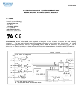
DESCRIPTION: BD30A Series PWM servo amplifiers are designed to drive brushless DC motors at a high switching
frequency. They are fully protected against over-voltage, over-current, over-heating and short-circuits. All models
interface with digital controllers that have a digital PWM output. PWM IN determines the output duty cycle. DIR IN
determines the direction of rotation. A single red/green LED indicates operating status. Current limit, set by DIP switches.
2. Sold & Serviced By:
ELECTROMATE
Toll Free Phone (877) SERVO98
Toll Free Fax (877) SERV099
BD30A Series
MODELS
POWER STAGE SPECIFICATIONS BD30A8 BD25A20 BD40A8 BD40A20
www.electromate.com
sales@electromate.com
DC SUPPLY VOLTAGE 20 - 80 V 40 - 190 V 20 - 80 V 40 - 190 V
PEAK CURRENT (2 sec. max., internally limited) ± 30 A ± 25 A ± 40 A ± 40 A
MAX. CONTINUOUS CURRENT (internally limited) ± 15 A ± 12.5 A ± 20 A ± 20 A
MINIMUM LOAD INDUCTANCE* 200 μH 250 μH 200 μH 250 μH
SWITCHING FREQUENCY 5 - 45 KHz
HEATSINK (BASE) TEMPERATURE RANGE -25o to +65o C, disables if > 65o C
POWER DISSIPATION AT CONT. CURRENT 25 W 55 W 35 W 90 W
OVER-VOLTAGE SHUT-DOWN (self reset) 86 V 195 V 86 V 195 V
MECHANICAL SPECIFICATIONS
POWER CONNECTOR Screw terminals
SIGNAL CONNECTOR Molex connector
SIZE 7.35 x 4.40 x 1.00 inches
186.7 x 111.7 x 25.4 mm
WEIGHT 1.5 lb.
0.68 kg
* Low inductance motors require external inductors.
3. BD30A Series
Sold & Serviced By:
PIN FUNCTIONS
CONNECTOR PIN NAME DESCRIPTION / NOTES I/O
1 MOTOR A Motor phase A connection O
2 MOTOR B Motor phase B connection O
P2 3 MOTOR C Motor phase C connection O
4 POWER GND Power ground GND
5 HIGH VOLTAGE DC power input I
1 PWM+ Same as pin 9 I
2 PWM- Pulse width modulated digital input I
3 DIR+ Same as pin 9 I
4 DIR- Direction input I
5 INH+ Same as pin 9 I
6 INH- Pull low to enable I
7 +FAULT Output transistor turns on and becomes high during
output short circuit, over-voltage, over O
P1 8 -FAULT
temperature, inhibit, and during power-up reset. Fault
condition indicated by red LED.
9 +5 IN +5 V in to drive opto coupler inputs. I
10 +V HALL 30 mA OUT
Power for HALL sensors,
short circuit protected, O
11 GND + 6 V @ 30 mA GND
12 HALL 1 HALL sensor inputs, logic levels,internal 2 KΩ pull-up.
13 HALL 2 Maximum low level input is 1.5 V, I
14 HALL 3 minimum high level input is 3.5 V
15 CURRENT MONITOR
OUT
Current monitor.
See B-20 for scaling. O
16 NC
ELECTROMATE
Toll Free Phone (877) SERVO98
Toll Free Fax (877) SERV099
www.electromate.com
sales@electromate.com
4. Sold & Serviced By:
ELECTROMATE
Toll Free Phone (877) SERVO98
Toll Free Fax (877) SERV099
BD30A Series
www.electromate.com
sales@electromate.com
SET-UP
See section "G" for engineering and installation notes.
CURRENT LIMIT ADJUSTMENTS
These amplifiers feature peak and continuous current limit adjustments. DIP switches reduce both peak and continuous
current limit. The ratio of peak/continuous current limit is fixed. The switches also adjust the scaling of CURR-MONITOR
output.
SW3 SW2 SW1 Peak current
(% of max.)
Continuous current
(% of max. cont.)
Current
BD25/30
Monitor
BD40
ON ON ON 100 % 100 % 4 A/V 4.8 A/V
OFF ON ON 50 % 50 % 2 A/V 2.4 A/V
OFF OFF ON 25 % 25 % 1 A/V 1.2 A/V
OFF OFF OFF 12.5 % 12.5 % 0.5 A/V 0.6 A/V
The actual current can be monitored at pin P1-15.
OPTICAL INPUT SIGNAL ISOLATION
PWM, DIR, INH, FAULT inputs are always isolated from the power section. If the isolation option is selected the Hall sensor
inputs (P1-10 through 14) are also isolated.
ORDERING INFORMATION
Models: BD30A8X, BD25A20X, BD40A8X, BD40A20X
With isolation:
Models: BD30A8IX, BD25A20IX, BD40A8IX, BD40A20IX
X indicates the current revision letter.
MOUNTING DIMENSIONS: See page E-6.