The most important mineral resource in Estonia is a specific kind of oil shale. About 99% of electric
and large share of thermal energy are being generated from oil shale. The importance of oil shale
production can not be overestimated for development of Estonian economy. It is estimated that about
80-90% of the total underground oil shale production is obtained by room-and-pillar method with
blasting. The method is cheap, highly productive and relatively simple to apply.
Call for Papers - International Journal of Intelligent Systems and Applicatio...
Room and pillar stability
1. METHODS OF MINING BLOCK STABILITY ANALYSIS FOR ROOM-AND-PILLAR
MINING WITH CONTINUOUS MINER IN ESTONIAN OIL SHALE MINES
Juri-Rivaldo Pastarus
Tallinn Technical University, Department of Mining, 82 Kopli St., 10412 Tallinn ESTONIA
Oleg Nikitin
Tallinn Technical University, Department of Mining, 82 Kopli St., 10412 Tallinn ESTONIA
ABSTRACT: The paper deals with prognosis and design methods for room-and-pillar mining with
continuous miner. Investigation based on the conventional calculation and conditional thickness
methods. The random inclination of real mining parameters from project one is taken into
consideration. Used methods guarantee the long-term stability of the roof and pillars. It is applicable in
different geological conditions, where the room-and-pillar mining system is used.
1. Introduction
The most important mineral resource in Estonia is a specific kind of oil shale. About 99% of electric
and large share of thermal energy are being generated from oil shale. The importance of oil shale
production can not be overestimated for development of Estonian economy. It is estimated that about
80-90% of the total underground oil shale production is obtained by room-and-pillar method with
blasting. The method is cheap, highly productive and relatively simple to apply. Now, it appears some
problems:
Decreasing of amount of oil shale production ( about 50%);
Old technology and fashioned mining machinery (low extraction factor);
Mining block stability (collapse and surface subsidence).
Elaborated new room-and-pillar mining method with continuous miner allows to give greatest
extraction factor, high productivity and leave no-conditional rock mass in underground mined out
areas. It is known that the deposit of oil shale is located in a densely populated and intensely farmed
district. Consequently, the mining system must guarantee the long-term stability of the pillars and roof.
Determination of the pillars and roof optimum parameters for new mining technology is the main aim
of the present work.
The conventional calculation formulas and conditional thickness methods were used. It is taken into
consideration the random inclination of the real mining parameters from project one. Used methods
allow to determine the room-and-pillar mining system parameters, which guarantee the long-term
stability. Used calculation methods give excellent results.
2. Geology
The commercially important oil shale bed is situated in the north-eastern part of Estonia. It stretches
from west to east for 200 km, and from north to south for 30 km. The oil shale bed lays in the form of a
flat bed having a small inclination in southern direction. It depth varies from 5 to 150 m. The oil shale
reserves in Estonia are estimated approximately at 4 thousand million tons.
The oil shale seams occur among the limestone seams in the Kukruse Regional Stage of the Middle
Ordovician. The commercial oil shale bed and immediate roof consist of oil shale and limestone seams.
The main roof consists of carbonate rocks of various thickness. The characteristics of the certain oil
shale and limestone seams are quite different. The compressive strength of oil shale is 20-40 MPa and
that of limestone is 40-80 MPa. The strength of the rocks increases in the southward direction. The
volume density is 1.5-1.8 Mg/m3
and 2.2-2.6 Mg/m3
respectively. The calorific value of dry oil shale is
about 7.5-18.8 MJ/kg depending of the seam and the area in the deposit.
3. Current and new mining systems
In Estonian oil shale mines the room-and-pillar mining system with blasting is used (Fig.1). It gives
the extraction factor about 80%. The field of an oil shale mine is divided into panels, which are
subdivided into mining blocks, approximately 300-350 m in width and from 600-800 m in length each.
2. Fig.1. Schematic layout of room-and-pillar mining in Estonia oil shale mines
A mining block usually consists of two semi-blocks. The oil shale bed is embedded at the depth of 40-
70 m. The height of the room is 2.8 m. The room is very stable when it is 6-10 m wide. In this case, the
bolting must still support the immediate roof. The pillars in a mining block are arranged in a singular
grid. Actual mining practice has shown that pillars with a square cross-section (30-40 m2
) suit best. A
work cycle lasts for over a week.
The area mined by room-and-pillar method reaches 100 km2
. It has become apparent that the
processes in overburden rocks and pillars have caused the mining block collapse accompanied by
significant subsidence of the ground surface. Up to present, 73 failures in Estonian oil shale mines have
been registered, which make up 11% of the total number of mining blocks and 3% of the mined out
area. It is visible that the problems of the mining blocks stability are very actual.
As a background for new room-and-pillar mining method with continuous miner was taking double-
face-longwall mining with blasting, used in ex-Leningrad oil shale minefields at the end of the 1970-s
(Nikitin 2001). Analysis showed that new mining method gives greatest extraction factor (up to 90%).
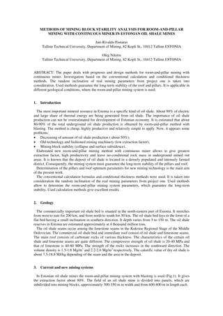
Room-and-pillar mining method with continuous miner is presented in Fig. 2. By this mining system,
the main and immediate roofs are supported by the pillars of different cross-sectional area. In this case,
bolting must still support the immediate roof. Very important environmental aspect is main roof control
method, which guarantee mining block stability for a long time without collapse of pillars and surface
subsidence.
3. Fig.2. Room-and-pillar mining method with continuous miner. Overburden load distribution on the
different pillars.
h – height of the room; H – depth of excavation; hi – thickness of the immediate roof; Hk – thickness of
the covered carbonate rock mass; Pf1 – load on the intra-block pillar; Pf2 – load on the intra-room pillar
4. Theoretical background
The parameters of new mining system can calculate by conventional formulas, used in Estonian oil
shale mines (Flow fleet…1988). This method is applicable for the room and pillar parameters
calculations up to 5 years. For the long-term calculations (over 5 years) it is recommended to increase
the factor of safety up to 1.5. The life-time of the pillars is verified by conditional thickness method.
The support coefficient and conditional thickness are presented by following formulas (Talve 1978,
Pastarus & Toomik 2000):
K = Sp/Sr, C = H/K (1)
where K – support coefficient; C – conditional thickness, m; Sp – cross-sectional area of a pillar, m2
; Sr
– roof area per pillar, m2
; H – thickness of the overburden rocks, m.
Geometrical interpretation of support coefficient and conditional thickness is given in Figure 3.
A B
Fig.3. Geometrical interpretation of support coefficient (A) and conditional thickness (B) (Talve 1978)
4. Conditional thickness represent the height of a prism whose cross-section equals the pillar cross-
section area. It contains sufficient information and is suitable for stability calculations. Conditional
thickness is related to the load on a pillar:
= C (2)
where - normal stress at the top of a pillar, Pa; - weight density of overburden rock, N/m3
.
Investigations showed that a mining block is stable if the conditional thickness C 350 m (Pastarus &
Toomik 2001). By these calculations the relative uncertainty in conditional thickness does not exceed
34 % at the 95 % confidence level. Consequently, a mining block is stable if the conditional thickness
C<230 m. The conditional thickness allows to calculate the stable dimensions of a pillar (Formula 1).
The comparison of the conditional thickness and conventional calculation methods is presented in
Fig.4.
0,0
5,0
10,0
15,0
20,0
25,0
30,0
35,0
40,0
45,0
20 30 40 50 60 70 80 90
Depth of excavation H,m
Widthofthepillarsx,m
Conditional thickness method; Conventional calculation method
Fig.4. Comparison of the conditional thickness and conventional calculation methods
The critical width of the immediate and main roof is determined of in situ conditions in Estonian oil
shale mines. The critical width is the greatest width that the rock above the mine can span before its
failure (Parker 1993). It is estimated that the first collapse of the main roof reaches up to 11.6 m.
On the other hand the real parameters of the roof and pillars depends on the applied technology and
quality of the mining works. Investigation has shown that by using the continuous miner, the random
inclination of the real pillars and room parameters from project one is less than 0.2 m. This factor is
taken into consideration in design of pillars and room parameters.
5. Design of the pillars and room parameters
The calculations are performed in the conditions of mine Ahtme. The excavation depth equals 42 m
and thickness of the commercial oil shale bed is 2.8 m. The length of the intra-block pillar is constant
(12 m), which is determined by technology. Minimum dimension of a pillar is limited and equals 2 m
(Flow fleet…1988). The results of the calculations are presented in Table 1.
Table 1. Pillar dimensions and conditional thickness parameters by different calculation methods
Conventional calculation
method
Conditional thickness
method
Real parameters
(project)
Type of
pillars
Width x length, m C*, m Width x length, m C*, m Width x length, m C*, m
Intra-block
Intra-room
8 x 12
1.2 x1.2
257
278
9.9 x 12
1.3 x 1.3
227
237
10 x 12
2 x 2**
225
100
* conditional thickness.
** limited by instruction for Estonian oil shale mines (Flow fleet…1988).
5. Investigation showed that the intra-block pillar dimensions equals 10 12 m, which gives the
conditional thickness C=225 m. The intra-room pillars dimensions are 2 2 m (C=100 m). These
parameters guarantee the long-term stability of the pillars and exclude the collapse of a mining block.
The influence of the random inclinations of the real room parameters on the stability of the
immediate and main roof is insignificant. In the calculations, it is not taken into consideration. The
immediate and main roof parameters are given in Table 2.
Table 2. Roof and room parameters in Estonian oil shale mines
Type of roof Thickness of the roof,
m
Critical width of the
roof, m
Width of the room
(project), m
Immediate roof
Main roof
Main roof (up to
height of 11.6 m)
3-4
35-45
11,6
12-15
45-60
35-39
8
-
28
Investigation showed that the safety factor of the calculated room parameters (8 and 28 m) is enough
large. Previous experiences in Estonian oil shale mines have shown that these parameters guarantee the
long-term stability of the rooms.
6 Conclusions and recommendations
1. The problem of the mining block stability and surface subsidence is very actual in a densely
populated and intensely farmed district, like NE Estonia.
2. The life-time of the pillars is calculated by conventional calculation formulas, used in Estonian oil
shale mines. The conditional thickness method allows to improve the quality of the calculations
and determine the stable parameters of the pillars and roof. Applied calculation method guarantee
the long time stability of the room and pillars. Collapse of a mining block and ground surface
subsidence is excluded.
3. Elaborated method is applicable in different geological conditions, where the room-and-pillar
mining system is used.
Estonian Science Foundation (Grant No. 5164, 2002-2005) supported the research.
References
1. Flow fleet of driving and extraction in the Estonian oil shale deposit by using mobile face haulage
units. 1988. Moscow (in Russian).
2. Nikitin, O. 2001. Monitoring and analysis of room-and-pillar mining with continuous miner in
Estonian oil shale mines. 3 International Conference “Environment. Technology. Resources.”
Rezekne, Latvia, 19-21 June 2001. P.116-121.
3. Parker, I. 1993. Mine pillar design in 1993: Computers have become the opiate of the mining
engineers. Mining Engineering, London, July and August: 714-717 and 1047-1050.
4. Pastarus, J.-R., Toomik, A. 2000. Environmental issues in oil shale mining. Mine Land
Reclamation and Ecological Restoration for the 21 Century. Proc. Int. Symp., Beijing, 16-18 May
2000, p. 406-411.
5. Pastarus, J.-R., Toomik,A. 2001. Roof and pillar stability prognosis in Estonian oil shale mines.
Rock Mechanics. Proc. of the ISRM Regional Symposium EUROCK 2001 “Rock Mechanics a
challenge for society”. Espoo, Finland, 4-7 June 2001, A.A.Balkema/Lisse/Abingdon/Exton
(PA)/Tokyo, p.849-853.
6. Talve, L. 1978. Check-up of real parameters of room-and-pillar mining in Estonia’s oil shale
mines. Ibid. 451: 23-35. (in Russian)