Power Line LiDAR Processing and Analysis
•Transferir como PPTX, PDF•
4 gostaram•1,745 visualizações

Power Lines LiDAR mapping and Offending vegetation detection.QA/QC Power lines analysis and Corridor Mapping. Customized engineering services from LiDAR procesing. PLS-CADD

Recomendados
Mais conteúdo relacionado
Semelhante a Power Line LiDAR Processing and Analysis
Semelhante a Power Line LiDAR Processing and Analysis (20)
Último
Último (20)
Power Line LiDAR Processing and Analysis
- 1. POWER LINES PROCESSING STEPS
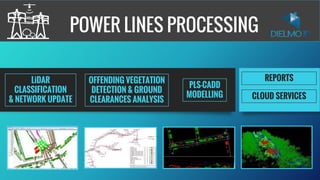
- 2. MAIN PRODUCTS REPORTS PLS-CADD MODELLING LiDAR CLASSIFICATION & NETWORK UPDATE OFFENDING VEGETATION DETECTION & GROUND CLEARANCE ANALYSIS CLOUD SERVICES
- 3. OUR EXPERIENCE AND BACKGROUND FLEXIBLE IN-HOUSE SOFTWARE CUSTOMIZED PRODUCTS AND SERVICES BEST QUALITY COMPETITIVE PRICING QA/QC 99,99% ACCURACY INTERNATIONAL EXPERIENCE + 85.000 KM With more than 85.000 km of experience in power line projects, we leverage extensive experience for your project. The ability to adapt our own software to provide optimal LiDAR processing solutions enables us to be flexible to any Client's specific requirements. This makes us an attractive alternative to traditional fixed flow line LiDAR processing solutions
- 4. LIDAR PROCESSING STEPS Delivery of raw LAS files. Auto classification of raw data Measure FL and Z errors in overlaps. Flight line adjustment in Z. Check and correct errors in XY. Select FL to refly Intensity image and objects > 3m mask. 2D vector of poles and conductors. QA of vectors with objects > 3m mask and reference vectors Check non capture regions Report non capture regions if necessary Select Study Data from Total Data Pool and Auto-classify Poles and Conductors Apply the flight line adjustment. LAS manual editing. Roads vectors. QA of vectors / Ids Compute PI and ground QA. QA of LAS classification Compute and edit patches. 2D vector of crossings. Prepare vectors to compute offending Vegetation (OV). Compute OV v1 QA of OV v1 Edit errors detected in OV v1. Recompute OV v2 Second QA of OV2. Edit errors detected in OV2. Compute the OV volume by span Prepare delivery of Offending Vegetation. Delivery of Offending Vegetation. Compute Report Premodeling QA of Report Premodeling. Edit errors detected in report pre-modeling. Insert Roads and MKP in LAS files. QA of overlaps with other Blocks. Prepare delivery of the other products. Delivery of the other products. 2- LiDAR CLASSIFICATION, QUALITY CONTROL, OFFENDING VEGETATION AND ERROR CORRECTION 1- DATA PREPARATION AND CORRECTION BEFORE CLASSIFICATION 3- PRE-MODELLING, REPORTS AND FINAL PRODUCTS GENERATION 1 2 3 4 5 6 7 8 9 10 11 12 13 14 15 16 17 18 19 20 21
- 5. LIDAR PROCESSING STEPS Description 1 2 3 4 5 6 7 8 9 10 11 12 13 14 15 16 17 18 19 20 21 Delivery of raw LAS files. Auto classification of raw data Measure FL and Z errors in overlaps. Flight line adjustment in Z. Check errors in XY. Correct errors in XY or select FL to refly. Intensity image and objects > 3m mask. 2D vector of poles and conductors. QA of vectors with objects > 3m mask and reference vectors Check non capture regions Report non capture regions if necessary Select Study Data from Total Data Pool and Auto-classify Poles and Conductors Apply the flight line adjustment. 1- DATA PREPARATION AND CORRECTION BEFORE CLASSIFICATION 6 WORKING DAYS
- 6. The LiDAR processing team receives raw .las files to begin the processing. We need a connected network of data before we are able start processing the depot. Disconnected parts or small parts are not suitable. We split the project in quadrants when working in large networks or projects DATA PREPARATION AND CORRECTION Delivery of raw LAS files
- 7. - Convert the original LAS files in ellipsoidal heights to orthometric heights. - Divide into 1x1 km tiles per flight line for efficient processing. - DTM, DSM, intensity images - LAS only with ground points - LAS with points > 3m. - Mask with points > 3m. DATA PREPARATION AND CORRECTION Auto processing of raw data
- 8. Based in the automatic DTM obtained in the previous point, algorithms examine height differences where flight lines overlap. DATA PREPARATION AND CORRECTION Measure Flight Line and height misalignments in overlaps
- 9. We identify the optimal correction factor to add to each flight line to minimize the Z (vertical) small misalignments in the overlaps. Any misalignment detected is examined individually and a flight line adjustment will be done to achieve the technical specifications. Survey points are used for ground truthing. DATA PREPARATION AND CORRECTION Flight line adjustment in Z
- 10. Visually we inspect the overlaps of flight lines to detect misalignments in XY. We examine any variations and choose between manual adjustment or re-flying the affected part. Rarely are significant issues identified at this stage but it is an important QA step DATA PREPARATION AND CORRECTION Check errors in XY
- 11. Any inconsistency detected is examined individually and points in error are removed. Usually these issues are solved removing the overlaps affected by the errors. If appropriate adjustments cannot be applied to deliver the specified accuracy, a recommendation is made to re-fly the affected flight line. DATA PREPARATION AND CORRECTION Correct Errors in XY or Select Flight Line to Re-fly
- 12. From the corrected LAS files, we prepare raster layers with the LiDAR intensity. The intensity image is used in the creation and QA of the road vectors (every physical material reflects the laser differently). We also prepare a raster layer mosaic with the points that are more than 3m above ground level. This mask is used for one stage of the QA of the conductor vectors, because we can identify easily them in the image. DATA PREPARATION AND CORRECTION Intensity image and objects > 3m mask
- 13. Using the GIS reference layers, we generate vector GIS layers with conductors and poles for the whole survey area. A layer is created for each voltage on the network. DATA PREPARATION AND CORRECTION 2D vector of poles and conductors
- 14. We then conduct a manual QA check to ensure consistency between the vectors created from the LiDAR data and utility- supplied reference layers. DATA PREPARATION AND CORRECTION QA of vectors with objects > 3m mask and reference vectors
- 15. Once the conductor vectors are done, we identify the regions that have not been captured and perform a QA to confirm their status, and identify no-fly areas. The non-captured regions are reported to the data capture team to re-fly. DATA PREPARATION AND CORRECTION Check Non-Captured Regions
- 16. Using the 2D vectors, we create new LAS files containing only the points inside a buffer from the conductors and poles. We clip the data set to minimize the processor time for each subsequent processing step. After that we use our custom software to automate the classification of poles based in the 2D vectors of poles obtained previously. DATA PREPARATION AND CORRECTION Select Study Data from Total Data Pool and Auto-classify Poles and Conductors
- 17. Join the LAS files in a single tile with all the flight lines. We prepare the corrected LAS files and add the height of each point to the correction factor from the corresponding flight line, obtained in a previous step. Join Flight Lines and Apply the Flight Line Adjustments DATA PREPARATION AND CORRECTION
- 18. Day 1 2 3 4 5 6 7 8 9 10 11 12 13 14 15 16 17 18 19 20 21 LAS manual editing. Roads vectors. QA of vectors / IDs Compute PI and ground QA. QA of LAS classification Compute and edit patches. 2D vector of crossings. Prepare vectors to compute offending Vegetation (OV). Compute OV v1 QA of OV v1 Edit errors detected in OV v1. Recompute OV v2 Second QA of OV2. Edit errors detected in OV2. Compute the OV volume by span Prepare delivery of Offending Vegetation. 2.- DATA PROCESSING, CLASSIFICATION, ANALYSYS & QC/QA LIDAR PROCESSING STEPS 10 WORKING DAYS
- 19. LAS manual editing Manual editing of the point cloud to match the classification table. DATA PROCESSING, ANALYSYS & QC/QA
- 20. LAS manual editing Manual editing of the point cloud to match the classification table. DATA PROCESSING, ANALYSYS & QC/QA
- 21. Road Vectors Using the .las files and intensity image, we prepare a vector layer of the roads crossing the network. DATA PROCESSING, ANALYSYS & QC/QA
- 22. QA of Vectors/IDs We assign references to the digital data of poles and conductors correlated to the utility-supplied GIS reference layers. Using GIS techniques, we assign the references automatically and carry out a QA and manual editing of the IDs based on the reference layers. DATA PROCESSING, ANALYSYS & QC/QA
- 23. Compute PI and ground QA We perform a QA of the ground classification to confirm that we have enough points in the ground in all the regions and that the DTM is correct. We also run an algorithm to compute the Points of Intersection (PI). We derive the X,Y for each PI using the poles vector layer. The height is calculated as the average of the ground points heights in a 1m buffer from the poles. DATA PROCESSING, ANALYSYS & QC/QA
- 24. QA of LAS classification After the manual classification, a different person checks the consistency of the data and the correspondence of the LAS classifications with the reference layers. DATA PROCESSING, ANALYSYS & QC/QA
- 25. 2D vector of crossings Once the LAS classification has been QA checked, we automatically develop a vector layer with the points that have been classified as crossings of any kind. We check this layer, then develop manually a separate vector layer of the crossings for each voltages. DATA PROCESSING, ANALYSYS & QC/QA
- 26. OV Specifications (Issc3 + 0.5 + 5.5) DATA PROCESSING, ANALYSYS & QC/QA
- 27. How Our Algorithm Works DATA PROCESSING, ANALYSYS & QC/QA
- 28. Prepare vectors to compute offending Vegetation (OV) Prepare the data to run the algorithm to detect the offending vegetation according to the specifications. - Tiles - Poles - Conductors - Classified LAS files DATA PROCESSING, ANALYSYS & QC/QA
- 29. Using our custom in-house software, we apply the algorithms to the data set of this depot, automatically and precisely generating a new LAS file with the offending vegetation classified according the specifications. For each voltage, we also generate a vector layer of polygons showing the extension of the OV and the minimum 3D distance. Compute OV V1 DATA PROCESSING, ANALYSYS & QC/QA
- 30. QA of OV v1 The results are validated against the specification. We have internal software to automatically zoom to each polygon ensuring that we check all the polygons to confirm each one is offending vegetation and not an error in the .las classification. DATA PROCESSING, ANALYSYS & QC/QA
- 31. Edit Errors Detected in OV v1 Manual correction of any misclassified points. DATA PROCESSING, ANALYSYS & QC/QA
- 32. Recompute OV v2 Once the errors detected have been corrected, we reapply the algorithms to the dataset of this block, automatically generating a second version of the .las files with the offending vegetation and the vectors for each voltage. DATA PROCESSING, ANALYSYS & QC/QA
- 33. QA of OV v2 We check the conformance of the result of the OV v2 to the specifications, paying particular attention to the classes with more risk and small polygons that could correspond to single points that are noise in the LAS files. Manual correction of any misclassified points. DATA PROCESSING, ANALYSYS & QC/QA
- 34. Day 1 2 3 4 5 6 7 8 9 10 11 12 13 14 15 16 17 18 19 20 21 Delivery of Offending Vegetation. Compute Report Premodelling QA of Report Premodelling. Edit errors detected in report pre-modelling. Insert Roads and MKP in LAS files. QA of overlaps with other Blocks. Prepare delivery of the other products. Delivery of the other products. 3.- Rest of products and final delivery LIDAR PROCESSING STEPS 8 WORKING DAYS
- 35. Report Pre-Modelling Specifications QA, REPORTS & DELIVERIES
- 36. Compute Report Pre-modelling Automatically measure the ground clearances between the ground/road surface and the conductor using the LiDAR data at ambient conditions for each different voltage and circuit present on the network, resulting in a vector layer with the results. It also indicates clearances to other circuits within the same span (attached) and circuits located on unattached structures. QA, REPORTS & DELIVERIES
- 37. QA of Report Premodelling Check the conformance of the result to the specifications. We have internal software to automatically zoom to each clearance measurement, ensuring that we check all the points to confirm that the measurement is accurate QA, REPORTS & DELIVERIES
- 38. QA of Report Premodelling QA, REPORTS & DELIVERIES
- 39. Edit errors detected in report pre-modelling Manual correction of errors in LiDAR classification. QA, REPORTS & DELIVERIES
- 40. Insert Roads and MKP in LAS files Finally, we compute the Model Key Points (MKP) from the ground points and we use the road vectors to automatically reclassify the ground points inside the road polygons from ground class to the ground in roads. QA, REPORTS & DELIVERIES
- 41. QA of overlaps with other Blocks To prepare the delivery of the LAS files, we check the consistency with overlapping depots to ensure continuity in the classification of the LAS files and in the height adjustment. QA, REPORTS & DELIVERIES
- 42. Prepare delivery We export the data to the different formats as requested in the specifications and merge with the data previously delivered. QA, REPORTS & DELIVERIES
- 43. POINTSTREES CLASSIFICATION DEACTIVATION INSERT SUPPORTSECTIONS CREATION LINE AT 50º LINE AT 75ºRE-INSERTING TREES PLS-CADD MODELLING OTHER LIDAR PROCESSING STEPS
- 44. OFFENDING VEGETATION ANALYSIS AND TREE FALL BY SPECIES OTHER LIDAR PROCESSING STEPS Offending vegetation detection and tree fall analysis by species. Estimations for X years period. • Offending vegetation distances and classes • Ground clearances and distances among wires. • Risk simulation for forestry species. • Tree fall risk for different species
- 45. FFCC AND CORRIDOR MAPPING FOR VEGETATION AND RISK DETECTION OTHER LIDAR PROCESSING STEPS Safety parameters modification and new algorithms generation for the analysis of railway and road infrastructures. • Safety distances to the ground. • Tree fall risk for flat areas but also for irregular areas and big slopes. • Other potential risks
- 46. CLOUD & ONLINE SOLUTIONS ONLINE PROJECTS, CLOUD SERVERS AND GEO-LINKS FOR POWER LINES LiDAR DATA SERVERS GIS WEB PORTALS ONLINE GIS PROJECTS & TOOLS GEO-LINK CLOUD SERVICES
- 47. ONLINE DATA MANAGEMENT AND PUBLICATION LiDAR DATA SERVER & WEB PORTALS LiDAR, Raster & Vector Web Portal customization Online tools, 3D and more Content Manager SEE VIDEO ONLINE
- 48. CLOUD SERVICES GEO-LINKS CLOUD DOWNLOAD PDF ONLINE HERE