Motor Control Using AND Gate
•Transferir como DOCX, PDF•
0 gostou•289 visualizações

Motor Control Using AND Gate

Recomendados
Mais conteúdo relacionado
Mais procurados
Mais procurados (16)
Semelhante a Motor Control Using AND Gate
Semelhante a Motor Control Using AND Gate (20)
Mais de Darani Daran
Mais de Darani Daran (20)
Último
Último (20)
Motor Control Using AND Gate
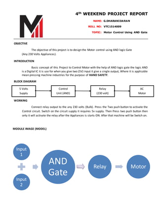
- 1. Relay Motor 4th WEEKEND PROJECT REPORT NAME: G.DHARANIDARAN ROLL NO: VTC1514009……… TOPIC: Motor Control Using AND Gate OBJECTIVE The objective of this project is to design the Motor control using AND logic Gate (Any 230 Volts Appliances). INTRODUCTION Basic concept of this Project to Control Motor with the help of AND logic gate the logic AND is a Digital IC it is use for when you give two (5V) input it give a single output, Where it is applicable mean pressing machine industries for the purpose of HAND SAFETY. BLOCK DIAGRAM WORKING Connect relay output to the any 230 volts (Bulb). Press the Two push button to activate the Control circuit. Switch on the circuit supply it requires 5v supply. Then Press two push button then only it will activate the relay after the Appliances is starts ON. After that machine will be Switch on. MODULE IMAGE (MODEL) 5 Volts Supply Control Unit (AND) Relay (230 volt) AC Motor Input 1 Input 2 AND Gate
- 2. PROJECT MODULE IMAGE LEARNINGS By doing in this project I learn working of AND logic gate and relay working how it changing the switch alternatingly (NO and NC).