Design and Simulation of Low Noise Amplifiers at 180nm and 90nm Technologies
A low power rf id transponder
1. RF design awards
A Low Power RF ID Transponder
By Raymond Page batteries require periodic field into a data-modulated signal
Wenzel Associates replacement, and the solar cell which can be transmitted back to
option would be both expensive the reader contributes to the low
This is the Grand Prize winner and vulnerable to the environment. manufacturing cost of this
in the design category of the 1993 A passive design eliminates the transponder design. The circuit
RF Design Awards Contest. This need for batteries by rectifying uses only one inexpensive
entry exhibited both innovative energy from the interrogating RF microwave semiconductor (a
use of RF technology and an field to power the circuitry. The diode) and allows all parts to be
elegant implementation of that harsh environment presented to an mounted on an FR-4 printed circuit
technology. The author was RF device mounted on the side of board with the patch antennas
awarded a NOISE COM model a rail car is a challenging problem. (Figure 1). By contrast, other
UFX-BER noise generator for bit Minimum clearance requirements, approaches use expensive
error rate testing. dirt, weather, vibration and an microwave parts, including SAW
extremely large chunk of ferro- devices, oscillators, mixers, filters
F or some time railroad magnetic material near the and amplifiers. Designs involving
companies have been antenna have to be considered. more RF circuitry tend to be power
wrestling with the problem of Additionally, the unit should be hungry, requiring increased RF
tracking rail cars. This has encapsulated.. Microstrip patch interrogation fields.
traditionally required manual log antennas have come to the rescue. Figure 2 shows the block
entry of identification numbers They afford a low profile and can diagram of the low power
displayed on the cars as they pass be made with an ordinary double- transponder. A 915 MHz receive
through the switching yard. Some sided printed circuit board. The antenna powers the
years ago, an effort was patch antenna is on the top and a rectifier/frequency doubler/AM
undertaken to use an optically ground plane is on the bottom, modulator. It provides a rectified
scanned ID system. Dirt and thereby eliminating the effects of DC source to the MCU which
optical registration problems led to the steel mounting surface. returns data to be AM modulated
its demise, forcing railroad onto the doubled frequency. An
companies to revert to the manual A Low Cost Transponder 1830 MHz antenna transmits the
system. RF engineers have come An unusually simple method of modulated carrier.
up with a solution, using converting the interrogating RF A reader, incorporating an
transponders mounted on the side
of the cars which are read by
interrogating transceivers
positioned along the track.
Design Considerations
A practical transponder design
must include minimal maintenance,
a rugged low profile and low cost.
The most elusive of these has
been low cost. Presented here is a
design which meets these
requirements along with a brief
discussion on the current state-of-
the-art in passive RF identification
transponders. An important design
constraint is that the transponder
require little or no maintenance.
Since no power is available from
the rail car, the only conventional
options are batteries or solar cells
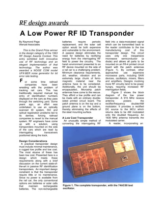
that maintain rechargeable Figure 1. The complete transponder, with the 74AC00 test
batteries. The non-rechargeable oscillator.
2. dB) and received with an antenna
915 MHz 1830 MHz unmodulated 915 MHz gain of 2 (3 dB) allows the
interrogation transmitter with low transponder to function from as far
(< -60 dBc) second harmonic as 20 feet away. This suggests that
Rectifier
distortion and an 1830 MHz AM just over 1 mW is adequate to
Frequency Doubler
receiver, is placed a relatively short energize the transponder.
AM Modulator
distance away from where the The transponder's surprisingly
Power Data transponder will pass (Figure 3). low power requirement is due to its
The amount of transmitted RF efficient means of rectification,
interrogation power needed to frequency doubling and
MCU
make the system function properly modulation. All of these functions
at a given distance can be are accomplished by a single
estimated by equation 1: microwave diode. A hybrid
Figure 2. Block diagram of the
schematic in Figure 4 details the
passive transponder.
Pr = PtGtGrλ2/(4πR)2 (1) circuit. The 915 MHz patch
10 '
antenna has two connections, a
Where Pr is the received power, DC return path connected at the
and Pt is the transmitted power zero impedance point and a
915 MHz
radiated by an antenna of gain Gt. transmission line matched to the
Gr is the gain of the receive 120 ohm impedance at the edge of
antenna, h is the free space the antenna. The transmission line
Reader
1830 MHz transceiver wavelength and R is the distance routes the signal to CR1 for
between transmitters. Gt and Gr rectification. A DC tap on the 1830
are the gains over an isotropic MHz antenna provides the power
radiator. A sufficient second connection for the MCU. (See side
harmonic return path signal will bar on microstrip patch antennas.)
occur for any combination of power Careful placement of CR1 along
gain and distance capable of the transmission line is crucial in
Figure 3. RF ID reader and energizing the MCU. creating the proper AC
transponder with rail car. One watt of power transmitted impedances for efficient frequency
with an antenna gain of 31.6 (16 doubling. The 1830 MHz antenna
becomes a 90 degree open stub at
915 MHz at the cathode of CR1,
effectively giving the 915 MHz
Trace length 2L signal a low impedance trap to
90 open stub
(including diode) work against (Figure 5). Since the
at 1830 MHz
Zo = 120 ohms transmission line does not provide
a similar low impedance on the
anode side of CR1, a 90 degree
open stub at 1830 MHz must be
1830 MHz CR1 added.
915 MHz Less than 100 uA are required
to power the MCU (Figure 6).
Consequently, little second
harmonic is produced by CR1,
C1 leaving plenty of modulation
CR2 headroom. Increased frequency
R1 multiplication occurs when the
output port of the MCU goes low
+VCC MCU providing a path to ground for
Output
Test Oscillator C2 rectified current via the 1 kohm
Port resistor, R1. Varying the value of
VCC R1 controls the modulation depth.
CR1, HP2811 CR2 and C2 work together to
CR2, HP5711 maintain sufficient voltage to the
C1, 100pF MCU while the voltage at C1 is
C2, 0.1 uF being pulled down by the
R1, 1K modulation action.
FB1 & FB2, SMT Ferrite Bead
MCU, MC68HC04
Figure 4. Hybrid schematic of transponder circuit.
3. Performance Improvements oscillators, phase locked frequency
As previously noted, the system Inherent compatibility with sources, multipliers and dividers. In
can operate up to 20 feet away. spread spectrum is provided by addition to having fun with
However, performance is this design since the returned electronics, he enjoys outdoor
measured at the 10-foot separation signal frequency is derived directly sports and music. He can be
required during normal operation. from the interrogation signal. reached at Wenzel Associates. by
For test purposes, a spectrum Frequency spreading is limited only equation 1 at a distance of 10 feet.
analyzer functions as the receiver. by the bandwidth of the patch
A 74AC00 gate oscillator in Figure antennas. With the simple addition Appendix A:
4 is substituted for the MCU to of a micro-power line receiver and Rectangular Microstrip Patch
simulate load and logic level the associated communications Antenna
conditions. The oscillator simplifies software, the transponder can be
confirmation of the concept. Three upgraded for two-way information The rectangular patch antenna is
kHz modulation is used for easy applications. Size reduction can be essentially a resonant microstrip
detection by the analyzer. accomplished by increasing with an electrical length of 1/2 the
The transponder transmits data operating frequency at the expense wavelength of the frequency to be
at 94 percent AM modulation. of costlier substrate material. transmitted or received. Microstrip
Measurements of the rectified Borrowing technology from missile patch antennas work well for
voltage (2.7 VDC) and current and aircraft radar technology the applications requiring a low profile,
(1.45 mA DC) give 3.9 mW total transponder could be made a part offering a height equal to the
power which correlates nicely with of the "skin" of its host. thickness of the printed circuit
the received power (5.3 mW) board from which they are made.
predicted by equation 1 at a Summary PTFE substrates are normally used
distance of 10 feet. This paper has described the to minimize dielectric losses which
design, 'operation and application affect the efficiency of patch
of a low-power RF identification antennas. However, FR-4 is a cost
transponder. The simple design is effective alternative for low power
spectrum friendly, requiring applications at frequencies below 2
minimal interrogation power and GHz. Microstrip antennas come in
allows easy conversion to spread all sizes and shapes. A rectangular
spectrum without modification to patch is chosen for its simple
the transponder. Designed with geometry and linear polarization
one inexpensive microwave part on when fed from the center of an
a single piece of FR-4 substrate, edge. The input impedance varies
component and manufacturing as a function of feed location. The
costs are kept down, potentially edge of a 112 wavelength antenna
opening up markets served has an input impedance of
Figure 5. Equivalent AC circuit exclusively by bar coding approximately 120 ohms which
of transponder showing RF technology. Other uses include drops to zero ohms as the feed
traps. automatic tolling, inventory tracking point is moved inboard to the
and military vehicle security. center of the antenna. This allows
easy impedance matching and
References provides a convenient means of
1. Howard W. Sams & Co., DC tapping the antenna as seen in
Reference Data for Radio the transponder design. For
Engineers, Chapter 27, Sixth simplicity, the dimensions of the
Edition, 1977. microstrip patch antennas in Figure
2. Robert E. Munson, “Conformal 9 are in terms of L, which is equal
Microstrip Antennas,” Microwave to 1/2 the electrical wavelength of
Journal, March 1988, pp. 91-109. the receive antenna (915 MHz). L
3. Alan Tam, “Principles of can be determined by equation 2:
Microstrip Design,” RF Design,
June 1988, pp. 29-34. L = 0.49 ( λ / εR ) (2)
Our Design Contest Winner where λ is the free-space
Figure 6. Current vs. clock fre- Raymond Page is a design wavelength and εR is the relative
quency for a typical 68HC04 engineer for Wenzel Associates, a permittivity of the printed circuit
MCU. manufacturer of high performance board. Bandwidth is determined by
crystal oscillators and frequency the substrate thickness and can be
standards. Ray specializes in low approximated for an SWR of less
noise designs for devices including than 2 by equation 3:
4. BW = I28 f2 t (3)
BW is in MHz, f is the operating
frequency in GHz, and t is the
substrate thickness in inches.
Applying equations 1 and 2 to the
transponder design using 0.125
inch FR-4 substrate material with
an effective permittivity of 4.7
results in a value of 2.92 inches for
L and a bandwidth of 13.4 MHz at
915 MHz.