

Recomendados
Mais conteúdo relacionado
Mais procurados
Mais procurados (20)
Destaque
Destaque (20)
Semelhante a Cairns-Kuranda Railway
Semelhante a Cairns-Kuranda Railway (20)
Mais de Australian Steamtrains
Mais de Australian Steamtrains (17)
Cairns-Kuranda Railway
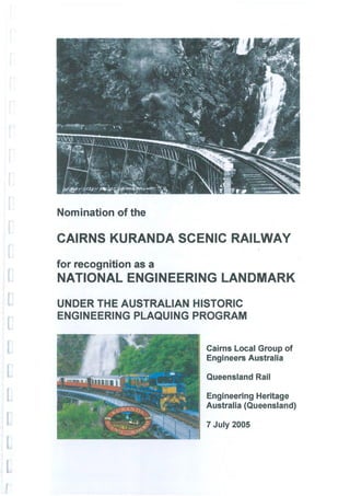
- 1. Nomination of the CAIRNS KURANDA SCENIC RAILWAY for recognition as a NATIONAL ENGINEERING LANDMARK UNDER THE AUSTRALIAN HISTORIC ENGINEERING PLAQUING PROGRAM Cairns Local Group of Engineers Australia Queensland Rail Engineering Heritage Australia (Queensland) 7 July 2005
- 2. NOMINATION FORM AUSTRALIAN HISTORIC ENGINEERING PLAQUING PROGRAM The Administrator Engineering Heritage Australia The Institution of Engineers Australia Engineering House 11 National Circuit Barton ACT 2600 Dear Madam, AUSTRALIAN HISTORIC ENGINEERING PLAQUING PROGRAM NOMINATION OF THE CAIRNS-KURANDA SCENIC RAILWAY FOR THE AWARD OF A NATIONAL ENGINEERING LANDMARK PLAQUE Location: This nomination covers a section of operating railway extending from central Cairns City to the top of the coastal range at Kuranda in Far North Queensland. Owner: Queensland Railways. The owner has been advised of this nomination and a letter of agreement is attached. Access to Site: Cairns and Kuranda are linked by both road and rail and are easily accessible. Sections of the line are accessible by road at various at grade crossings and are visible at the grade separation of the track and the western arterial by-pass of the city. Being an operating railway, the work may be inspected during the rail journey up the range. Passengers on special tourist trains are given a commentary on the works, their construction, the people involved, and the subsequent use of the line. The institution's plaques will be placed on an adjoining face of an existing 1991 plaqued pyramidal cairn, which commemorates the centenary of the completion of the railway on the Kuranda station platform, near a wheelchair lift and which is accessible by all train passengers. Nominating Body: Cairns Local Group, Engineers Australia We hope this nomination provides the Plaquing Committee with sufficient material on which to access the nomination, but we will be happy to supply further information if it is desired, and is available. The owner and our committee would like to have the Plaquing ceremony in conjunction with the Northern Engineering Conference on the rd 3 September 2005. The owner is planning to provide a special train for the event. Peter DeRoma - ~ Chairman - Cai~L6cal Group, Engineers Australia Date· · i 0·C Robi ck C man - Engineering Heritage Australia (Queensland) Date.... S/l/q.f. . . .
- 3. ENGINEERING HERITAGE AUSTRALIA PLAQUING NOMINATION ASSESSMENT FORM 1. BASIC DATA: Item Name: CAIRNS KURANDA RAILWAY Other/Former Names: Redlynch Kuranda railway Barron Gorge railway Location: Cairns Railway Station 0 0 16 58.6'S 145 46.4'E [369300mE 8128200mN] Kuranda Railway Station 0 0 16 49.2'8 145 38.4'E [355000mE 8139800mN] (Plaque to be installed at Kuranda Railway Station) Map references are to GDA94 Zone 55K Address: Situated partly in Cairns City and partly in Mareeba Shire Suburb or nearest town: Cairns suburbs of City, North Cairns, Edge Hill, Aeroglen, Freshwater, Redlynch and Kamerunga. Barron Gorge National Park and Kuranda Township within Mareeba Shire State: Queensland Local Government Areas: Cairns City and Mareeba Shire Owner: Queensland Railways Current Use: Scenic tourist railway Former Use: Arterial rail feeder for mining, agricultural, and timber exports through the port of Cairns and for passenger transport in Far North Queensland Designer: Queensland Government Railways (now QR) Maker or Builder: John Robb, contractor for Queensland Railways Year Started: 1886 Year Completed: 1891 Physical Description: Like all Queensland railway lines the Cairns-Kuranda Railway (33.233 km.), is of narrow gauge (1067mm) construction. It extends from the Cairns Central Business District generally in a north-westerly, thence westerly and south-westerly direction to the foot of the main coastal range at Redlynch station. The Redlynch- Kuranda section (21.666km.) is a continuous climb. The line initially heads south up Freshwater Creek valley to Horseshoe Bend and then back north along the slopes of the Lamb Range to gain height above Redlynch at grades of 1 in 48. It then proceeds in a general north- westerly and westerly direction up the slopes of the
- 4. Barron River gorge to the top of the Barron falls at Kuranda at an average grade of 1 in 60 with 5 chain radius curves Construction of the railway included 106 cuttings, 15 tunnels totalling 1,746 metres in length, 244 metres of steel bridge spans and 1,894 metres of timber bridges. The side slopes of the gorge are between 40° and 50° and equal the natural angle of repose for the loose material as shown in photographs. These slopes are believed to be uniquely steeper and looser than those of other mountain railways in Australia. The steepness of the slopes and their geological structure have resulted in major stability problems during construction and for the maintenance and operation of the track during more than one hundred and ten years since completion. The station building at Kuranda is the oldest surviving reinforced concrete station in Queensland and also one of the few remaining fully signal-interlocked stations. Physical Condition: The track structures, rock side slopes and embankments have received continuous upgrading and stabilisation since original construction, yet still retain much of their original integrity. Very high seasonal rainfall has regularly induced major landslides and rock falls, which have required cleaning and stabilisation to allow resumption of safe train operations. Due to topographical and geological restraints, only minimal realignment has been undertaken since construction. Further realignment would involve major earth and rock works and would result in the shortening and steepening of the track. Much of the original rainforest which covered the slopes was cleared during construction but has regenerated to the extent that most of the range through which the railway passes is now a World Heritage Listed National Park. It remains, together with its minimum radius curves, permanent way of design frozen in time but is a safe and adequate track for the moderately slow picturesque tourist trains using the facility. Modifications: The original 60lb O.S. rails were progressively replaced with stronger 631b A.S. rails along with replacement of sleepers during routine maintenance over the years since construction. Complete re-railing with 41 kg rails and re-sleepering with a combination of steel and timber sleepers was undertaken between 1997 and 2001. The bridges on this railway were originally constructed for 8 tonne axle load rolling stock. In.1926, as a result of the introduction of heavier rolling stock, Queensland Rail upgraded the bridges to carry 10 tonne axle loads. In 1998 all of the bridges were again strengthened to carry 16 tonne axle loads to accommodate sugar traffic
- 5. from the Atherton Tablelands. Other significant structural modifications include: • Stoney Ck bridge, which is the most outstanding feature of this Railway, was originally constructed with a ballast deck, which was replaced by timber longitudinals in 1922. • Surprise Ck bridge was originally constructed with a steel lattice truss main span and timber approach spans. The timber spans were replaced with steel lattice truss spans reclaimed from the old Indooroopilly Bridge in Brisbane in the early 1900's. • The original timber bridge over Mervyn Ck was replaced by a steel plate girder bridge on a new alignment in 1920. • The timber spans over the main channel of Jumrum Ck were replaced with a steel BFB span in 1962. Historical Notes & Dates: The settlement of the port of Cairns in 1876 provided the closest outlet for the new Hodgkinson Goldfield discovered in 1876 at Thornborough (west of Mareeba). In 1880 tin was discovered at Herberton (south of Mareeba) and in February 1882, the Queensland Government decided the mines warranted a railway. A report by Surveyor Monk in 1884 culminated in a Government decision on 10 September to select Cairns as the terminus over Geraldton (now Innisfail) and Port Douglas. The Queensland Parliament approved plans on 30 October 1885 and the first contract was awarded on April 1 1886. The Cairns Kuranda railway was constructed in two sections. The first of 11.567km to the foot of the range was first let to contractor P C Smith, then to W McBride, and was finally completed by government day labour. Work started on 10 May 1886 and the section was opened on 8 October 1887. The second contract of 25.448km was for the range section and was awarded to John Robb of Melbourne on 28 January 1887. That section was opened to Myola at the top of the range, and 3.782km beyond Kuranda on 15 June 1891. The schedule of rates contract price was approximately £290,000 and the final cost including extras approximately £900,000 with some £240,000 disallowed under arbitration. These costs exclude the steel for the rails and bridges, which were imported from the UK by the Queensland Government and supplied to the contractor. Design and most of the supervision of the contract was by the Chief Engineer for the Northern Division, Willoughby Hannam MICE. During the 104 years since completion, a great many landslides and washouts have occurred. These are associated with the annual wet seasons during which the rainfall averages 1768mm over 5 months. The maximum recorded one-day rainfall is 512mm.ln 1911,
- 6. more than 3000mm of rain occurred in conjunction with three cyclones and over the 4-month period from 1 January to 30 April, the line was closed for all but two weeks due to major restoration and repairs with up to 800 men employed. Listings: Queensland Heritage Register www.epa.q/d.gov.au/cu/turaLheritage 5 listings 600676 Christmas Creek Rail Bridge 600685 Stoney Creek Rail Bridge 600686 Surprise Creek Rail Bridge 600755 Cairns to Kuranda Railway 601502 Kuranda Railway Station National Trust of Queensland have ceased listing Australian Heritage Database www.deh.gov.au/heritage/commonwea/th 3 listings 15964 Christmas Creek Rail Bridge 15965 Surprise Creek Rail Bridge 15966 Stoney Creek Rail Bridge Location Map: Extract from NATMAP Topographic Map SE 55-02 Edition 2 1996 CAIRNS 1:250000
- 7. 2. ASSESSMENT OF SIGNIFICANCE Historic Phase: The Cairns-Kuranda railway was built during a significant period of rapid discovery and exploitation of Australia's mineral wealth. Government owned railways were seen as the main mode of transport for passengers and freight. Development in the 1880's boom was so rapid that some projects were what we now refer to as fast tracked with construction approved and commencing before adequate engineering investigations were performed. Construction of this line required a largely manual workforce of about 1500, which was recruited from Ireland and Italy. Many of the workers elected to remain in Australia afterwards. Historic Individuals or Association: The survey was commenced by Robert Ballard MICE. The remainder of the survey, the design of works and the majority of the supervision was controlled by Willoughby Hannam MICE, Chief Engineer of the Northern Division of Queensland Govemment Railways. The work was completed under T H Annett, after Hannam's death. Hannam's son engineered many Queensland branch lines, and his grandson Henry was Project Engineer for the major Mareeba-Dimbulah Irrigation Project. The contractor was the nationally famed John Robb (1834- 1896) of Melbourne who arrived in Australia about 1854 and as Overend & Robb or by himself performed large civil and railway works in Victoria, South Australia, Western Australia, before his work on the Cairns-Kuranda line. Robb invested in NSW sugar mills and pastoral properties, Victorian banks and real estate, and South Australian real estate. The depression of the early 1890s and his losses in Cairns bankrupted him. (See the article from the Australian Dictionary of Biography in the Appendix 4). Creative or technical achievement: The construction was a technical feat of its time due to its benching in old slide planes of decomposed rock, much of it at the natural angle of repose reaching to the bed of the river hundreds of metres below. The degree of weathering of the underlying metamorphic rock, together with deep movement of such material for many centuries, involved uphill batter slopes of height to 175 metres. No doubt much of the finished work contributed to the future high maintenance costs from lack of knowledge of modern soil/rock mechanics. The curved steel lattice bridge at the head of the short Stoney Creek valley passes across the almost sheer face of Stoney Creek falls is certainly unique on Queensland Railways. It has always been recognised, as being of great aesthetic appeal. With the falls as a background the bridge has provided a spectacle for millions of private and publicity photographs.
- 8. Research Potential Experience gained from the maintenance of the cuttings, embankments and underlying rock would have played no small part in the appraisal of the tunnelling design on the same southern slopes of the gorge for the second Barron Falls Hydro-Electric Scheme, constructed in 1959-1961. At one stage, that design was altered to relocate deeper in to the side of the gorge avoiding ancient slip material. Social: There are three major aspects to the social significance of the Cairns-Kuranda railway line. Firstly the line provided the most important catalyst for the development of Cairns and the permanent settlement of the Atherton and Evelyn Tablelands. The network behind Cairns had grown to about 800 km by 1926. At the same time as mining activity declined, other industries were developed. Subsequent major industries were the felling, milling and transportation of cabinet and structural timbers. In different areas timber clearing was followed by dairying and agriculture, while in the dryer areas mining was followed by irrigated tobacco, rice, sugar and coffee. Further to the west the railway serviced a huge pastoral area. Secondly during World War 2 the railway serviced a transitory Australian and U.S. military population of about 250,000. They assembled and trained on the tablelands and later returned for R&R or hospitalisation. Thirdly, though improvements in roads and vehicles have seen the closure of about half of the network, the line has served the new tourist industry. General affluence and globalisation have led to Cairns and the Tableland becoming desirable tourist destinations, and the Cairns-Kuranda railway becoming a key tourist attraction. Rarity: Australia, as an old eroded continent, has few gorges and escarpments, and fewer still that have been conquered by railway engineers. The gorge section of the railway is believed to be the most extensive section of precipitous range railway construction in the Commonwealth. The line and its fifteen tunnels were all largely excavated by hand and explosives. The steel lattice bridge, curved in plan, passing across the almost sheer face of Stoney Creek falls is certainly unique on Queensland Railways. DeSigned by District Engineer for the Cairns Railway by John Gwynneth, the bridge consists of four, fifty foot spans alternating with three thirty foot tower spans and timber approaches on concrete piers, all on a four chain radius curve. It has been recognised from the time of its construction, as of great aesthetic appeal and provides a spectacle, along with the falls as a background, such as is generally achieved by even more spectacular and technically adventurous bridges. Representativeness: - The railway with its vista backdrop has survived its original
- 9. construction purpose as an element of pioneering necessity in the development of Far Northern Australia. It has evolved into a focus for part of the overseas visitor tourism agenda and represents an excellent example of the past fulfilment of the need for transportation of goods and people. In this it perhaps equals or surpasses the difficulty of a 3 feet gauge rail construction in Alaska in 1897-9 from Skagway through White Pass to Whitehorse for the KlondikelYukon goldfields access. Integrity/Intactness: The alignment and many of the structures are in their original condition. The whole of the permanent way, together with its structures are of a high standard for a Queensland Railway branch line, it having been upgraded to take the additional loadings anticipated from the new sugar industry of the tablelands. It has been maintained to the high standards for which the civil engineering branch in the Department is well known. 3. STATEMENT OF SIGNIFICANCE: Cairns Kuranda railway is of unique historic, technical, aesthetic and cultural significance to the nation. Built at the end of the 19th century it illustrates the use of railways as a development tool for the nation. It played its part in making Australia, for a time, the world's leading producer of gold and tin. The contractor, John Robb, was a man with a national reputation. His subsequent bankruptcy illustrates the catastrophic results of the depression of the nineties. As an engineering feat, it is the only example in Australia of a narrow gauge railway constructed in an otherwise inaccessible gorge through rainforest and under tropical weather conditions. It was constructed at a time when the region was deemed too harsh an environment for Europeans to work in. The social significance of the railway is both national and regional. The migrant labour aided population growth, the industries serviced by the railway attracted further population. In World War 2 the line was vitally significant infrastructure in the defence of Australia. The Cairns-Kuranda scenic railway is highly significant aesthetically. The railway forms the premier scenic public transport medium in Australia. Surrounded by the World Heritage Wet Tropics, it is unique in providing the sole land based access to the Barron Gorge. It also includes the unique Stoney Creek Falls Bridge which is curved in plan, and is arguably Australia's most photographed rail bridge. This is a real railway, with an authentic history, and whose structures and alignment are essentially as they were at the end th of the 19 century. In a leisurely fashion, Australian and overseas visitors can see the railway structures, the rainforest, the distant coral reefs, and the cane fields framed by the gorge.
- 10. Assessed Significance: National Images: see Appendix 1 References: Broughton, A 0, (1991) Cairns Range Railway 1886-1891, Cairns Historical Society. Kerr, J, (1993) ORlDEH Historical Survey of OR Hallam, G (2004) private communication (see Appendix 3) Nairn, B, (1976) Australian Dictionary of Biography Vol. 6 p33-4 Hobler, G A, (1903) The Construction of the Mountain Section of the Cairns Railway, Minutes of Proceedings Vol. 153 Part 3, Institution of Civil Engineers (see Appendix 2)
- 11. Proposed Plaque Wording: CAIRNS KURANDA TOURIST RAILWAY This dramatic railway climbs 323m in 21.7km through the rainforest of the World Heritage Wet Tropics and across the very steep loose sides of Barron Gorge. John Robb, the contractor, and his European migrant workforce men built the line, bridges and tunnels between 1886 and 1891. The Chief Engineers, Willoughby Hannam and T H Annett designed and supervised the railway for the Queensland Government Railways. The railway developed a large mineral and agricultural area of Far North Queensland. During World War 2 it serviced huge camps and hospitals. The railway is now the premier scenic public transport experience in Australia. The Institution of Engineers Australia Queensland Railways 2005 (100 words)
- 12. Chief Executive Officer GPO Box 1429 Brisbane Qld 4001 Floor 14 Railcentre 1 305 Edward Street Brisbane Qld 4000 Telephone 0732351371 Facsimile 0732351856 Email: ceoffice@qr.com.au Mr Stephen Davies Secretary Caims Local Group Queensland Division Engineers Australia PO Box 7953 CAIRNS QLD 4870 Dear Mr Davies PROPOSED PLAQUING OF THE KURANDA RANGE RAILWAY Thank you for your letter of 25 August 2004 advising that your Group wishes to nominate the Cairns Kuranda Railway for recognition as a National Engineering Landmark. In view of the significance of this railway in the development of QR and of Far North Queensland, it is a pleasure to support this nomination. I agree with a plaque being installed at a mutually acceptable location. This could possibly be located on the platform at Kuranda at a location which compliments the Centenary Cairn which was placed there some years ago. Would you please liaise with Mr Greg Hallam (Phone No. 3235-1367) regarding appropriate representation from QR on the local plaquing committee. Yours sincerely Bob Scheuber Chief Executive Officer "0 5 September 2004 A.B. N. 47 S64 947 2&4
- 13. APPENDICES THESE PAGES ARE NOT NUMBERED BECAUSE OF THE DIFFERENT FILE TYPES AND SOURCES USED The material is in the order listed below Appendix 1: Images Appendix 2: Hobner's ICE paper Appendix 3: Kerr and Hallam line-side notes Appendix 4: Biography of John Robb Appendix 5: Biography of W Hannam
- 14. Barron Gorge from near Robb's Monument. The gorge is geologically recent being the result of the Barron River's capture of the headwaters of the Mitchell River. Photo 69640r from the John Oxley Library (State Library of Queensland Barron Falls with dry-weather flow before Tinaroo Dam was built Photo 116477r from the John Oxley Library (State Library of Queensland)
- 15. "Robb's monument" at the paint of a major spur
- 16. I " 'I' ,', -:~ . , ~ 'VI~~ :" Working conditions on the line. Photos 67224r and 27405r John Oxley Library
- 17. Willoughby Hannam (1838-1893) Chief Engineer of the Northern Division of the Queensland Government Railways 1885-9 Photo 162892r John Oxley Library Current plaque on the cairn at Kuranda Railway Station
- 18. Cairn at Kuranda Railway Station
- 19. 214 nOBLER ON OONSTRUOTION OF MOUNTAIN SECTION OF [Selected SECT. IIo-OTHER SELECTED PAPERS. (Paper No. 3368.) " The Construotion of the Mountain Seotion of the Cairns Railway, Queensland." By GEORGE ALExANnER HOBLER, Assoc. M. Inst. CoEo TilE Queensland Government Railway between Cairns and Mareeba has a total length of 4.6 miles 50 chains, and was con- structed in three sections, the work being let by a separate contract for each section. Section No. 1 is 8 miles in length; section No. 2 is 15 miles 18 chains (Fig. ], PIa te 5); and section No. 3, ending at Mareeba, is 23 miles 20 chains. In this Paper the Author presents a description of the principal works oomprised in Seotion No. 2, the mountain section, of the line, and the general methods adopted in its construotion. Description of the country.-For about 60 miles northwards and about 100 miles southwards from Trinity Harbour, upon the shores of which Cairns is situated, there rises the face of an immense table-land at a distance from the sea-coast varying, approximately, between 1 mile and 15 miles. rrhe height of this table-land ranges between about 1,100 feet and 3,500 feet above sea-level. The country between the sea-coast and the face of the table-land being practioally flat, and having a rich soil, well watered, and covered with dense jungle, a humid atmosphere, with no frosts, and an annual rainfall ranging between 90 inches and 200 inches, is an ideal country for sugar-cultivation; consequently a large and increasing industry is carried on. The eastern face of the table- land is covered with heavy jungle, which extends back for a con- siderable distance on the top of the table-land. ~rhe soil is immensely rioh, and the jungle is 80 feet to 150 feet in height, and is full of almost unlimited quantities of valuable timbers suitable for furniture, house-building, etc., including immense quantities of red cedar. The marketable trees of the latter range between 7 feet and 27 feet in girth at the butt, and in some cases attain a height of about 200 feet. The dense mass of under- growth consists chiefly of lawyer thorn vines, stinging-tree, wild banana, creepers, etc., which render surveying a difficult and often a painful operation Severe frosts are occasionally experienced
- 20. Papers.] THE OAlRNS RAILWA.Y, QUEENSLAND. 215 on the higher portions of the table-land, as muoh as 17° F. below freezing-point having been registered. Leaving the jungle oountry and going further west or inland, the oountry becomes very dry and barren, but immensely rioh in gold, copper, silver, tin, lead, and other metals. Passing through the main traot of this mineral- bearing oountry further into the interior, large tracts of fine grazing country are met with, upon which a oonsiderable number of cattle are raised. It will, therefore, be seen that for the supply of provisions, etc., to this inland country, and in order to give facilities for opening up the mining, agrioultural and pastoral industries, a railwaY)Jp the faoe of this table-land, and running inland, was absolutely necessary. After a considerable amount of exploration and surveying, the Government decided to construct the line from Cairns, and it has now been completed as far as Mareeba,46i miles, from which point the Chillagoe Company have continued it for a distance of 102 miles further west, with several branoh-lines, and the Government have approved of the extension of a branoh from Mareebn., 22 miles in length, along the table-land, parallel with the sea-coast, to tap the timber and agricultural land at Atherton. Location of the Line.-The location of the line, espeoially the preliminary surveys, was an arduous and difficult undertaking, owing to the steep hill-sides, the dense jungle, and the hostility of the natives, who, at that time, were very treaoherous, and constantly looted the survey-camps, besides spearing any white people who fell into their hands. Trial lines were run down from the top of the table-land, on gradients of 1 in 60 and 1 in 50, and from these cross-seotions were taken and the permanent line was located. The asoent of the face of the table-land begins at 71 miles, near Redlynch Station on Seotion No. 1, at a height above sea-level of 18 feet (Fig. 2, Plate 5) and with the exception of 10 chains of level line at 11 miles, ascends by gradients ranging between 1 in 50 and 1 in 99, to 11~ miles; the ruling gradient on this portion of the section is 1 in 50, with 5-chain curves. Between 11~. miles and 14~ miles (Stoney Creek) a gradient of 1 in 60, with 5-ohain ourves, is maintained continuously throughout. Between 14! miles and 19 miles 10 chains, the summit of the asoent, 1,073 feet above sea-level, the ruling gradient is 1 in 55, with 5-ohain curves, the easiest gradient on this portion 'of the line being 1 in 103, for a length of 13 chains. Between 19 miles 10 ohains and the end of the seotion, at 23 miles 30 chains, the line is practically level. The ascent from foot to top of the table-land is therefore 1,055 feet in 11 miles 70 chains, or an average rise of 88 feet per
- 21. 216 nOBLER ON OONSTRUOTION OF MOUNTA.IN SEOTION OF [Selected mile. With the exoeption of a 4-chain curve at Stoney Creek Bridge, and two other curves of 4! chains radius, the sharpest curves are of 5 chains radius. In the total length of this section, 15! miles, there are 9 chains length of 4-chain curve, 14 chains of 4~-chain curves, 4 miles 20 chains of 5-chain curves, 74 chains of 6-chain curves, and 74 chains of curves not less than 7 chains radius, leaving 8 miles 67 chains of straight road. The minimum length of straight line between reverse-curves of 5 chains radius is 90 links. The average annual rainfall in this portion of the Cairns District is about 90 inches to 100 inches, and as much as 72 inches was registered in one month during the construction of this section. The prinoipal portion of the rain falls generally during the months of January, February, March and April. Oarriage of Material and Plant.-Owing to the rugged nature of the country, the construction of dray-roads was not practicable along the site of the works. Pack-tra(ks were therefore made, contouring round the ravines and mountain-spurs, at formation- level of the rail way. Tracks were also cut down the leading spurs of the mountain to the main Government camp at Kamerunga, and to the contractor's camp at Stoney Creek. Up and along these tracks, the plant, tools and explosives for culverts, earthworks, etc., and the cement and sand for concrete culverts, were trans- ported on mule-back, mules being found more serviceable than horses. The sand had to be taken from the Barron River, none being obtainable in the gullies on the sides of the hill. The Portland cement was imported from England in barrels, each containing 4k cubic feet. As the barrels were too unwieldly and heavy to lift and pack on the mules, thick canvas bags, each holding about 1 cwt. of cement, were made, and when filled were carried on the mules up to the site of the works. The sand required for use in the bridge-piers and culverts was also taken up in a similar manner. As the plate-laying advanced, the material was taken to the head of the road and was carried on along the line by mules. Sand and cement for lining tunnels were, of course, taken up by trains, the rails being laid through the tunnels as soon as these were excava ted. Olearing.-Owing to the steepness of the mountain-side, the distance to whioh the slopes of the cuttings ran baok, and the great height of the jungle, a considerable quantity of clearing had to be done above these slopes, on the high side of the line. The clearing cost approximately £770 per mile. Earthworks.-The earthworks were heavy, especially in cuttings and embankments. A large amount of benching in the seats of
- 22. Papers.] THE OAlliNS RAlLWAY, QUEENSLAND. 217 embankments had also to be done, owing to the steep slope of the hill-sides. The width of formation in cuttings and embankments was 14 feet, the formation being level across on straight road, and canted on curves to suit the super-elevation of the outer rail. No definite slopes could be fixed for the upper or higher side of the cuttings between about 12 miles and 19 miles, as, owing to the steep and treacherous nature of the ground, the slopes had to be suited to each individual cutting; they are, therefore, somewhat irregular, ranging principally between! to 1 and 1 to 1. The slopes of embankments are I! to 1. Cross-sections of the original surface of the ground were taken, and when the outtings were completed cross-sections of the aotual excavation were taken, at the same points of chainage, and from these the contents were cal- culated. The cross-sections were taken with the theodolite, readings on the staff being taken upon angles of elevation or depression. Owing to the ourves in cuttings being, of oourse, principally con- cave towards the mountain-spurs, and the centres of gravity of the oross-sections considerably inwards from the oentre-line of the railway, it follows that the product of the mean area of the crOS8- section and the length measured on the oentre-line of the rail way, would give in such curves much more than the actual volume of the excavation. Similarly, less than the actual volume would be given on convex ourves. The following method of oalculating the amount of excavation from cuttings on curves was therefore adopted. Eaoh cross-seotion, after being plotted, was divided into sections by vertical lines 20 feet apart, measured from the centre- line. These were lettered A, B, e, etc. Tables were prepared giving the distances apart, measured parallel to the centre-line, of the middle ordinates of oorresponding lettered sections. The mean areas of the oorresponding lettered sections were then multiplied by the tabular distance apart of these sections. Many of the upper or higher sides of the outtings exceed 300 feet in height measured along the slope, which, in such oases, is roughly i to 1. By following this method of measurement in the outtings between 121 miles and 18 miles, the total quantity excavated was fo~nd to be 2,261,482 cubic yards, whereas the volume obtained by multi- plying the mean area of the cross-sections by their dista.nce apart, measured on the centre-line, was 2,333,326 oubio yards, an excess of 71,844 cubic yards above that obtained by the more correot method. Between 8 miles and 12 miles, and between 19 miles and the end of the section, the material excavated in cuttings was principally red soil and decomposed rock. Between 12 miles and 19 miles the
- 23. 218 HOBLER ON CONSTRUCTION OF MOUNTAIN SEorION OF [Selected country was of an exceedingly treacherous nature, especially in the Barron Gorge, between 16 miles and 19 miles, where the average angle of slope of the ground was about 45°. Almost the whole of the surface of the ground in this gorge was covered with a layer of loose disjointed rotten rook and soil to a depth of 15 feet to 25 feet. The line had therefore to be kept well into the hill- side, and the batters of the upper sides of the cuttings had to be carried up a great distance in consequence, Figs. 3, Plate 5. The cross-section at 16 miles 78 chains shows a large land-slip above the top of the cutting, which took place a few months after the cutting was finished to the original slopes. The earth appears to have slipped oft' a large greasy rock, and, since the opening of the line for traffio, has broken further baok still, causing continual inconvenience during the wet weather, to which this district is BU bject. Between 16 miles and 19 miles there are only a few small embankments; the bulk of the material from cuttings on this portion of the section was therefore run right over the side of the formation in one handling. The total quantity of earthwork, including excavation for tunnels, culverts and bridges, was about 3,076,000 cubic yards. Of this amount, 2,823,983 cubic yards was in cutting to bank and spoil, 34-,962 cubic yards was in side- cutting, and 74,169 cubic yards was in diverts, inlets and outlets. The actual cost to the contractor, of exoavation in centre-cutting to bank and spoil, was approximately 2 shillings per cubic yard. Bridges and Oulverts.-The following riveted steel lattice-girder bridges were erected : -..- bridge of one lOO-foot span with timber approaches, the girders resting upon wrought-iron cylinders, 3 feet 6 inches in diameter, set in concrete; a bridge of one lOO-foot span on concrete piers with timber approaches; a bridge of one lOO-foot span on concrete abutments; a bridge of one 75·foot span on concrete piers with timber approaches; and a bridge of two 50-foot spans and one 30-foot span built upon a 5-chain ourve, and having concrete piers at each end and timber approaches, the 30-foot span forming a tower-span between the two 50-foot spans, with wrought- iron lattice-piers, footed in concrete. A bridge at Stoney Creek Falls, built upon a 4-chain curve, consists of four 50-foot spans alternating with three 30-foot tower-spans, with wrought-iron lattice legs, the end piers being of concrete and the approaches of timber, Figs. 4, Plate 5. The total length of steel bridges on this section is 800 feet. The oontractor was paid £15 per ton for the erection of the sub-structure of all bridges and the girders of Stoney Creek Bridge, and £20 per ton for the erection of the super-structure of
- 24. Papers.] THE OAIRNS RAILWA.Y, QUEENSLAND. 219 the other bridges. Altogether, there are 339 tons of ironwork in these bridges. The ironwork was all out out and fitted and partly riveted up at MeRsrs. Walkers, Limited, of Maryborough, Queens- land. The girders were sent from these works in seotions oon- venient for handling in the steamers and on the railway, and when landed at the bridge-site, the riveting was oompleted, and the girders were launched into their plaoes by means of derrioks. The total oost of the ironwork, delivered at Cairns, was £7,850 ; the cost of oarriage to the site, and erection by the oontraotor, amounted to £6,330, making a total of £14,180, equal to an average price of about £42 per ton for the ironwork erected in place. The contraot prioes for the different portions of the ironwork, deliverec1 in Cairns from Messrs. Walkers, were the following :- Cast iron • • £18 to £20 per ton. Wrought iron. • • . • • • 24" 28 Steel 23" 80 All the bridges were designed to carry locomotives with a maximum axle-load of 9 tons. In addition to these bridges, fifty-nine wooden trestle-bridges were built, having an aggregate length of 6,215 feet, many of them upon 5-chain curves. On shallow bridges the spans are alternately 14 feet and 18 feet, without corbels, the two single girders being round logs 17 inches in diameter, faoed on the top to receive the transoms and faced at the ends underneath to rest upon the head- stocks. The deeper bridges have spans of 22 feet, 24 feet, 26 feet and 28 feet. The 22-foot spans consist of two double girders with corbels, and the 24-foot, 26-foot and 28-foot spans consist of three double girders with oorbels, each double girder being composed of two logs 17 inches in diameter, faced where they rest on each other, and the upper one faced on the top for transoms. The trestles are built of two to five round piles, according to the height of the bridge and the span used; in deep bridges the outside piles are battered 1 in 6, and, if the line is curved, double piers 5 feet apart are used. The trestles are braced with sawn hardwood waling and bracing, 9 inches by 5 inches, and the transoms are of hardwood, 8 feet by 9 inches by 5 inches. The bottoms of the excavation for the trestle-piers were levelled up with cement-concrete, and on this the sills were laid. In many of the ravines where the flow of water was not sufficient to necessitate the erection of a bridge, it was still found necessary, owing to the steepness of the ground, to build bridges, the ground being too steep for banks to stand, and adequate retaining-walls
- 25. 220 HOBLER ON CONSTRUCTION OF MOUNT.A.IN SECTION OF [Selected could only have been provided at a much greater cost than that of the bridges. For example, at 13k miles a ravine having a drainage-area of 15 acres, and requiring a waterway of about 8 square feet, had to be crossed by a timber tresUe-bridge, 252 feet in length, the sills of the trestle-piers being, in several cases, 60 feet below rail-level; the average slope of the mountain side at this place is about i to 1. The minor waterways were provided for by conorete culverts, ranging between 2 feet and. 7 feet in diameter, and also by log- culverts and box-culverts. The concrete used in culverts was gauged 4 of broken stone and 2 of sand to 1 of Portland cement. Concrete culverts were placed under deep embankments. Log- oulvel't.~ were plaoed in shallow embankments where box-culverts oould not be made large enough to carry the water. Log-culverts were made in the following sizes-2 feet by 2 feet, 3 feet by 2 feet, 3 feet by 3 feet, 4 feet by 2 feet, double 3 feet by 2 feet, and double 4 feet by 2 feet. They are constructed of side-logs, faced on three sides and tre-nailed together, the floor and top being made of split slabs and the head wall of dressed logs. Box-culverts were made of sawn hardwood, 2 inches in thickness, the maximum size of culvert used being 2 feet by 2 feet. In many of the ravines the upper sides of the banks were filled in to formation-level with spoil from the outtings, and the water was divided and led by contour- drains to short culverts through the line at formation-level, at each end of the embankment, thus saving the necessity for long concrete culverts low down in the embankments. During the construction of this section the difficulty of procuring good forest timber was very great, and a large quantity of jungle timbers was therefore used in the bridges, but with unsatis- factory results, these timbers proving unsuitable for piles, head- stocks, corbels and girders-especially for girders. At the same time, one of these timbers, hickory, has proved a very useful timber for baoking-boards, foot-planking, sleepers, crossing-timbers, box-drains, fencing and house-building. From experience gained on this line in the maintenance of timber struotures, the Author considers that in building railways through long stretches of tropical jungle, the employment of jungle timbers in permanent bridge structures should only be resorted to if it cannot possibly be avoided, and the most vigilant discrimination should be observed in the selection of the timber, for, apart from the risk of accident involved, the cost of maintenance and renewals constitutes a serious item. Retaining- Walls.-On the flatter portions of the line, retaining- walls were made of dry-sto~J.e work, large roughly-dressed stones
- 26. Papers.] THE OAIRNS RAILWA.Y, QUEENSLAND. 221 being used, well packed with spawls and with concrete copings on top. On the steep mountain-sides the walls were made of cement-concrete composed of broken stone, sand and cement, gauged 6, 3, and 1. - Tunnels.-There are fifteen tunnels on this section, Nos. 1 to 14 ranging between 56 yards and 196 yards in length, and No. 15 being 470 yards in length. The total length of tunnelling is 1,910 yards. Twelve of these tunnels are built partly on 5-chain curves. In Tunnel No. 11 there are 5-chain reverse-curves, and in No. 15 there is a 7!-chain curve at one end, a I5-chain curve at the other end, and a 5-chain curve in the middle. The cross-section of the tunnels is shown in Figs. 5, Plate 5. They are lined with cement- concrete throughout, the minimum thickness of the lining being 15 inches, increased to a maximum thickness of 21 inches in treach- erous ground, where extra pressure was likely to occur. No inverts were put in, but footings under the side-walls were shaped to form water-tables on each side of the road. The tunnels are 17 feet in height from formation-level, 14 feet in width at formation-level, and 15 feet in width at 6 feet above formation-level, and are built for a single road. The formation was made level across, and the necessary super-elevation of the outer rail on curved portions was given by extra ballast under the sleepers. The ground through which the tunnels were driven consisted almost entirely of disjointed rock of an exceedingly treacherous nature, and in such ground the contractor preferred to carry out the excavation by top-headings, except where the necessity of taking through material from adjacent cuttings, or for assisting the work beyond, made it more economical to use bottom-head- ings. In solid rock, top-headings were used. Top-headings were 9 feet by 9 feet and bottom-headings 11 feet by 10 feet. When widened out to full dimensions, the tunnel was timbered as shown in Figs. 5, Plate 5, and the permanent-way was laid to enable construction-trains to pass through. The tunnels, as excavated, were supported upon the timbers for 3 months to 15 months before the concrete lining was put in. This may be considered rather a long time, especially in country subject to a heavy rain- fall, but practically no detrimental results were apparent from the practice followed. Particulars of the time occupied in excavating and lining each tunnel, including headwalls, etc., are given in the Appendix. In the majority of cases all timber was taken out as the concrete lining was put in. In a few instances it was con- iidered impossible to take several of the crown-bars out without risking the colb,ps6 of the tunnel, and they were accordingly left
- 27. 222 nOBLER ON OONSTR'UO'XION OF MOUNTAIN SEOTION OF [Selected in, being packed round with extra concrete. Tunnels Nos. 1 to 13 were lined throughout with cement-conorete composed of broken stone, fine sand, and Portland cement, gauged 4, 2, and 1. Nos. 14 and 15 were lined with concrete, made of river gravel and cement, gauged 6 to 1, the gravel being tested to ensure the presence of a sufficient percentage of fine sand. The tunnels are all on gradients ranging between 1 in 50 and 1 in 60. The concrete was mixed at the higher ends of the tunnels, except in Tunnel No. 15 which was concreted from both ends, so that the loaded trollies could be run down-hill to the point where the lining operations were in pro- gress. The excavation was taken out as nearly as possible to the exact dimensions for concrete lining, cavities being packed with stone, and weep-holes provided at formation-level about every 10 feet. After the footings had been put in, the concrete lining was brought up on each side, with wooden centering; the side-walls were put in first, continuously, to a height of 11 feet 6 inches, then each side of the arch, leaving a keying-course of about 2 feet 6 inches in width, which was filled in from the end. In almost all cases, the tunnels being in very steep sidelong ground, the main thrust is at an angle of about 45°, and the Author is of opinion that, where the thrust of the ground is not vertical, the method adopted of building in the concrete lining is open to objection, it being essential that the lining should form a continuous bond. Subsequent events during the maintenance of the line have tended to support this view. In February, 1896, a shock of earthquake caused fraoture of a portion of the lining at the Mareeba end of Tunnel No. 15. Apparently through the stone packing outside the lining of the outer or weaker side having been defective, the weight of the ground twisted the tunnel over a few inches, and the keying-course moved a way from the inner half of the arch and slightly downwards; the thrust of the ground then fractured the inner half of the arch right down to the top of the side-wall. A length of about 60 feet of the lining, from the top of the side-wall on the left-hand side to within 2 feet of the footings on the right- hand side, had to be out out and renewed. The lining was then built in sections of 6 feet in length and was carrieu round in one operation. At Tunnel No. 15, the original survey ran round the outside of the hill, where it was proposed to build an iron bridge and two short tunnels, but having regard to the nature of the ground it was deoided to put the whole of this part of the line into one tunnel. To prevent delay to the works which had been started along the line ahead of this place, it was necessary. to drive the
- 28. Papers.] THE OAIRNS RAILWA.Y, QUEENSLAND. 223 tunnel as quickly as possible, and for this purpose three ad its were driven in from the side of the hill to the centre-line of the railway, and the driving of the tunnel was carried on from eigh faces at once. The average quantity of excavation per lineal yard in tunnels was 32 cubio yards, the quantity of concrete required for lining being 8 cubio yards. The cost of the cement-concrete used in tunnels was about 55 shillings per cubic yard, including the cost of centering and general supervision. The cost of cement landed on the site of the works was about 20 shillings per cask, machine-broken stone costing 5 shillings per cubic yard and sand 2 shillings per cubio yard. The cost of mixing the concrete and putting it in place was, on an average, about 8 shillings per cubic yard. The cost of excavation was, on an average, about 15 shillings per cubic yard, including timbering and explosives; and the cost of the tunnels completed was approximately £46 per lineal yard. The driving of the tunnels was all done by hand. Per'lnanent-way.-From the beginning of this section to 9 miles 6 chains the road was laid with steel rails, 26 feet in length, of Vignoles pattern, weighing 41± lbs. per yard with four-hole strap fish-plates, weighing 10 lbs. per pair, the rails being spiked to the sleepers with fir-inch dog-spikes. The remainder of the road was laid with 60-lh. steel rails, 24 feet in length, of Vignoles pattern, with four-hole strap fish-plates, weighing 15 lbs. per pair, the rails being spiked to the sleepers with ~-inch dog-spikes. The rails were bent with So hand screw-press. A portion of the sleepers were of sawn timbers, 6 feet 9 inches, by 9 inches, by 4~ inches, and the remainder were half-round, cut from trees ranging between 10 inches and 1 foot in diameter. The timber principally used for sleepers was hickory from the jungle, and bloodwood from the forest country. The contractor's price for sleepers was 3 shillings each. Gravel ballast was procured from the bed of the Barron River at Kamerunga, to which place a temporary branch-line, about 11 mile in length, was laid. The contractor's price for ballast was 4 shillings per cubic yard. There are 2,640 sleepers to the mile on straight road, and curves flatter than 7 chains radius, and 2,880 sleepers to the mile on curves of radius not exceeding 7 chains. Approximately 960 cubio yards of ballast was used per mile of line, the dept.h of ballast under the sleepers being 4 inches. The.·Author is of opinion, from experience gained in the subsequent maintenance of this line, that in tropical countries having a heavy rainfall and a humid atmosphere, where the growth of grass and weeds constitutes a. serious item in the cost of maintenance, gra.vel
- 29. 224 HOBLER ON CONSTRUCTION OF MOUNTAIN SECTION OF [Selected ballast is much superior to broken-stone ballast, the cost of weeding being reduced to approximately one-sixth. The roots of grass and weeds in gravel can be easily, quickly, and effectively removed, whereas in broken stone the roots break off in the metal and sprout up again almost immediately; the broken metal also cuts and jars the men's hands. The gauge of the line is 3 feet 6 inches on the straight, and the rule now in force with regard to the gauge on curves is that it shall be 3 feet 6~ inches on curves of radius not exceeding 7 chains, and 3 feet 6i inches on curves of radius between 8 chains and 20 chains. The weights and costs of the permanent-way material used are given in the Appendix. The maximum speed round sharp curves allowed on this section is 18 miles an hour for passenger-trains, and 15 miles an hour for mixed passenger- and goods-trains. The rates of wages paid by the contractor through- out were, for labourers, 8s. per day, gangers, 128. per day, carpen- ters, 128. to 148. per day, hammer- and drill-men, 98. per day, and for plate-layers 88. and 98. per day. Locomotives.-The engines at present in use on this line are of two classes, known as "B 13" and" B 15" of the Queensland Railways. The former has six wheels coupled, the diameter of the wheels being 3 feet 3 inches, and the wheel-base 10 feet 4 inches; the cynnders are 13 inches in diameter, and the load on each axle of the coupled wheels is 51,l tons. The weight of the engine is 23 tons 16 cwts., and of the tender 22 tons 10 cwts., or a total weight of 46 tons 6 cwts. The" B 15" class of engine has six wheels coupled, 3 feet in diameter, the wheel-base being 8 feet 9 inches; the cylinders are 15 hlChes in diameter, and the load on each axle of the coupled wheels is 7 tons. The weight of the engine is 27 tons 19 cwts., and of the tender 23 tons 15 cwts, or a combined weight of 51 tons 14 cwts. From Redlynch to Kuranda the" B 13" engine hauls a load. of about 80 tons, and the" B 15" engine 120 tons, exclusivo of engine and tender. The survey of this section was commenced under Mr. Robert Ballard, M. Inst. C.E., then Chief Engineer of the Central and Northern Division of the Queensland Rail ways, and was con tinued under the late Mr. Willoughby Hannam, M. Inst. C.E., Chief Engineer of the Northern Division, under whom also the works were designed and the construction partly carried out. The work was finally completed under Mr. T. H. Annett, Mr. Hannam's suocessor. The construotion was commenoed in January 1887, and was completed in June 1891. The total amount paid to the contractor, Mr. John Robb, exclusive of arbitration fees, was
- 30. Papers.] THE CAIRNS RAILWAY, QUEENSLAND. 225 £891,916, equal to £58,779 per mile. Rails and fastenings and iron- work for the iron and steel bridges were provided by the Government Rail way Department, and the cost of these is therefore not included in this amount. All the surveys were carried out by the Govern- ment Railway Surveyors. The Author was engaged as Assistant Surveyor in the survey of the line' and in the preparation of drawings, and afterwards as Assistant Engineer in the construction of the line, and on two occasions had charge of the work as Acting Resident Engineer, for about 5 months and 7 months respectively, during the absence on leave of Mr. J. G. Gwynneth, the Resident Engineer. On the completion of this section, the Author was appointed Distriot Engineer for Maintenance and Construction in the Cairns District. The Paper is acompanied by two tracings, from which Plate 5 has been prepared; and by nine photographs, and the following Appendix. [ApPE}lDU. [TIlE INST. C.E. VOL. CLm.] Q
- 31. 226 nOBLER ON CONSTRUOTION OF MOtliT.AIN ~EC'1ION OF [E'e]ected APPENDIX. Tnm OccurIED IN EXCAVATING TUNNELS, IKCL"CDING HEADWALLS, ETC. Tuun~l ! Wo~k Done I W0t: k Done Total Exca- ~umber.; Commenced. Completed. " DUTlllg First DUTlllg LWlt 'I'vatlon. Month. Month. -----------I ----- Cubic Yards. -----_._- Cuhlc Yards. Cubic Yards . 1 •Tune,1887 September, ]887 ,B60 440 2308 2 June,1887 September, 1887 ]28 150 2723 a July, ]887 April, 1888 188 48 3864 4 July, 1887 :May, 1888 30 50 3271 5 August, 1887 July,IR88 50 485 2842 G August, 1887 May, 1888 90 50 :-3920 7 August, 1887 ' February, 1888 20 40 18U9 8 July, 1887 I October, 1888 60 'i0 3714 9 September 1887 • November, 1888 40 5 633S. 10 April,1888 : June, 18139 '25 5 4021 11 September, 18871 May, 1889 '50 5 2968 12 January, 1888 August, 1888' 10 2G4 2881 13 April,1888 September, 1889 90 10 3126 14 I March, 1890 I June, 1890 10 2999 15 12 April, 1890 November, 1890 I 10 15264 TIME OCOUPIED IN L1NING TtNNELB. Tunnel Commenced. Completed. Total Number. COllcrete used. - - - - . : - - - - - - - - - - ----_._-----_. - - - - Yards. Cubic -- 1 31 August, 1888 17 October, 1888 694 2 September, 1888 November, 1888 698 3 25 October, 1888 23 January. 1889 978 4 20 January, 1889 20 April, 1889 834 5 28 January, 1889 22 April, 1889 726 6 3 April. 1889 3t May, 1889 994 7 20 April, 1889 27 May, 1889 474 8 25 May, 1889 20 July, 1889 938 9 3t May, 1889 20 August, 1889 1586 10 24 July, 1889 18 September, 1889 1018 11 17 August, 1889 30 September, 1889 758 12 23 September, 1889 9 November, 1889 738 13 22 October, 1889 9 December, 1889 794 14 19 July, 1890 4 October, 1890 766 15 3 November, 1890 30 March, 1891 3791
- 32. Papers.] TIIE OAIRNS RAILWA.Y, QUEENSLAND. 227 WEIGHTS AND COSTS OF RAILS AND F ASTENINGS PER MILE OF LINE. 4l1-Lb. Materia.l.-Rails, 64'82 tons; fish-pl1l.tes, 1'82 ton; fish·bolts, O' 50 ton: dog-spikes, 2' 36 tons. 60-Lb. Materia1.-Rails. 94: 28 tons; fish-plates, 2' 95 tons: fish-bolts, o'93 ton: dog-spikes, 2' 65 tons. The approximate costs of rails and fastenings delivered at Cairns from England were- 4ll-Lb. Material :- Per 'run. £. 8. d. Rails 580 Fish-plates 700 Fish-holts • 16 3 0 Dog-spikes 16 6 0 GO-Lb. Material :- Per Ton. £. 8. d. Rails • 6 11 0 Fish-plates 840 Fish-bolts . 17 14 11 Dog-spikes 17 4 0 QUANTITIES OF THE PRINCIPAL ITEMS OF WORK, ETC., BY FINAL MEA8unElIEN'TS. Clearing Earthworks :- Cutting to bank and spoil • 2,823,983 cubic yards. Excavation in water-tables 828 " drains at ends of cuttings 1,664 " " side-cutting 34,962 " " side-drains • 22,253 " " diverts, inlets and outlets 74,169 " " benching seats of embank-} " " ments. • . . • 4,454 " " " ,. station-yards 624 ., " Surface forming. 51 lineal chains. Fencing • 585 " " Iron and steel bridges:- Exca.vation for foundations for piers. 10,426 oubic yards. Cement concrete in piers 3,138 " " Iron and steel work 389 tons. Pa.inting • 7,081 eqUlue yard& Q 2 .
- 33. 228 HOBLER ON MOUNTAIN SEOTION OF CAIR:KS RAILWAY, [Selected Timber bridges :- Excavation for foundations, etc. • 36,26:1 cubic yards. Cemet;lt-concrete under wooden trestle-} pIers. . . . • , . • • . 1,538 " Round timber in piles, head stocks, girders} and corbels. . . . , . • . 74,{,98 lineal feet. Sawn timber in transoms, wales and f hra~s, footplo.uks, longitudinals and 23,130 cubic feet. backlDg-logs . . . . . . . Ironwork. IB5,758Ibs. Painting, 26,122 square yards. Tu.rring . 8,215 Timber and concrete culverts:- Dox-drains 12 inches by 12 inches to.} 2,852 lincal feet. 24 inches by 2:1 inches Log culverts 2 feet by 2 feet to 7 feet} by 2 feet • • . • . • . . 913 Earthenwa.re pipe-drains 3 inches to} 18 inches in diameter • . 5,253 Excavation for concrete in culverts 2,888 cubic yarus. Cement-concrete in cuh.. crts 1,119 " Retaining-walls ;- Dry-stone work , 419 Cement-concrete work • 5i7 Tunnel~:- Excavation in tunnels • 62,048 " ,. side drives-tullnel No. 15 1,602 Cement-concrete in tunnels 15,687 Stone packing in side drives . 288 ElI.rth-filliug in side drives 511 " " Stone pitching-9 inches deep 613 square yards. Permanent way ;- Sleepers • 38,351 Ballast 14,645 cubic yards. Squared timber in points and crossings. 146 feet.
- 35. LINE-SIDE NOTES ON THE CAIRNS-KURANDA RAILWAY 1999 Greg Hallam, Historical Adviser, QR John Kerr, Historian and advisor to QR and Queensland EPA Cairns was proclaimed a port in October 1876, the closest outlet for the new Hodgkinson Goldfield south of the Palmer. The subsequent discovery of tin at Herberton proved to be sufficiently profitable to warrant a railway. Herberton was 882 metres above sea level, making any railway a difficult undertaking. There were three rival termini, Mourilyan Harbour, Cairns and Port Douglas. The 'bump' road from Port Douglas provided the best access to the tinfield, far easier than the alternative, pack tracks from Cairns. Cairns had been established to provide a shorter route to the Hodkinson Goldfield than from Cooktown. The difficulties of crossing the coastal range meant that with the establishment of Port Douglas with its much easier track to the Hodkinson field, Cairns decreased in importance. The surveying of the projected route was delayed due to the difficulty of contracting surveyors who had experience enough in surveying a railway line. Surveyor G W Monk was commissioned and marked a line from Herberton to the coast at Cairns. After two years of railway survey, the Government announced on 10 September 1884 that it had chosen Cairns. It was the better port and surveyors Stuart, Amos and Monk, considered the precipitous slopes of the Barron Gorge offered a better route than lines from Port Douglas or up the Mulgrave valley. The decision fuelled land speculation at Cairns and vehement opposition from Port Douglas. Cairns had been chosen in ignorance of the unstable geology of the Barron Gorge, otherwise Port Douglas or the scarcely explored route from Mourilyan Harbour might have been selected. Parliament approved plans for the first 39 kilometres on 30 October 1885 but the contract let to P C Smith on 1 April 1886 was for only a third of the distance. Smith lacked the experience for even such a short section and was allowed to transfer it to W McBride. The line opened on 8 October 1887 with two return services provided four days per week. The terminus at the 8 mile was named Redlynch within weeks of the opening. The original survey to the base of the range was through Brinsmead Gap but a cheaper although longer route survey skirting Edge Hill was adopted instead. A deviation was constructed in 1911 with a direct route through to North Cairns. The major section of the ascent of the Barron Gorge began with the awarding of Section 2 of the contract to John Robb on 26 January 1887 for £ 290, 984. It began with a long horseshoe to gain height, followed by a 15 kilometre railway line with 15 tunnels ascending the gorge to the top of Barron Falls 317 metres above Redlynch. Nineteen tunnels had been originally planned but four were subsequently replaced by cuttings. The line then followed the Barron River to Kuranda, terminating at Myola. Robb was an experienced contractor, and brought hundreds of men to the job, many of them from Italy. To aid construction, he built a two kilometre long branch from Redlynch to the main construction camp at Kamerunga beside the Barron River. Public trains extended to Kamerunga from 20 October 1888, two return trips daily except Sundays. Trains had to reverse at Redlynch as the line was built mainly for the hauling of construction material up the range. Services to Kamerunga ended when trains began running to Myola. Kerr and Hallam Line-side notes on the Cairns-Kuranda Line Page 1 of 4
- 36. During the construction, camps for navvies were established at most of the cuttings and at each of the tunnel headings along the range section. Kamerunga which was situated at the base of the range section was the headquarters John Robbls main office. At the height of construction over 1500 workers were employed along the length of line. Sand from the bed of the Barron River was used as the base material for concrete work on the second section. Wagons were forwarded along the permanent way to the limit of major construction work, at which point sand was bagged, packed onto mules and forwarded along ledges worked into the mountainside to the various jobs. The building of the longest tunnel, No. 15, was the most difficult of the tunnel jobs on the range. The difficulties encountered meant that in 1889 a temporary hold up in construction took place. Chief Engineer Stanley and one of the three railway commissioners arrived in November to authorize construction of deviation work within the tunnel. When work was recommenced additional drives were started allowing eight faces to be worked on simultaneously. Most of the work undertaken in driving of the tunnels was by hand. The ground was especially treacherous to work on within the Barron Gorge. The average slope of the ground was 45 degrees, covered with a disjointed layer of decomposed soil and rock varying in depth from 5 to 8 metres. The usual danger from the extensive use of explosives in the tunnels and cuttings was increased by the unstable nature of the rock and the precipitate drop down the side of the gorge. What was probably the first death on the range occurred on 18 July 1887 when Ganger Willoughby was killed by flying stone at the 12 mile during blasting. In November Martin Brennan and A Corbett were killed when three metres of the Herberton end of Tunnel No. 4 collapsed. 23 deaths were confirmed on the construction of the range section. Bridgework was also a major element of the construction work on Section Two. Total length of steel required to complete the bridgework was around 800 feet (260 metres), utilising nearly three hundred (290 tonnes) tons of steel. The steel work was all cut, fitted and partly riveted by Walkers Ltd of Maryborough at a cost of £7,850. The Stoney Creek Bridge built across Stoney Creek falls, is the best known, and most photographed engineering structure on a line. The bridge is built on a 4 chain radius curve (80 metre) Both the contract price and the completion date of 26 July 1888 were greatly exceeded. In common with all railway contracts, the price was calculated by multiplying the quantity of each type of work required by the quoted price and summing up the individual amounts. If the survey was altered to require more excavation, the government paid for the extra at the schedule rate. This schedule of prices system reduced the risk to the contractor and resulted in keener prices. For Robbls contract, the extra work was so large that he was paid £880,406 plus £20,807 as a result of the arbitration of his £262,311 claim for extras. Despite the enormous difficulties encountered during construction, the line proved to be well built, a tribute to Willoughby Hannam who had to survey many deviations when the original route proved impossible to construct. The line opened to Myola on 15 June 1891. By this stage Kuranda had become the most important station on the section, and a tourist location due to its proximity to the Barron Falls. The initial timetable provided two trains each way daily, and allowed only 75 minutes for the journey, even with the sharp succession of curves. A timetable issued in August re-timetabled the range climb for 90 minutes. The railway between Cairns and Mareeba was constructed in three sections, of which Section 2, between Redlynch and Myola, was the most difficult and expensive to construct, but which now makes accessible some of the most spectacular scenery in Queensland. Kerr and Hallam Line-side notes on the Cairns-Kuranda Line Page 2 of 4
- 37. The railway runs nearly south-south-east from Redlynch station (7 miles 15 chains-11.567km, elevation: 34 feet-10.4m) with easy curves and grades to Jungara (8 miles 47 chains- 13.820km, elev.: 169 feet-54.5m). Just over half a mile south of Jungara there is a 5 chain (100.65 metre) horseshoe curve at which point the main ascent begins. The line now proceeds northwards along the lower slopes of the Lamb Range to the first of the fifteen tunnels, thirteen of which are between Jungara and Stoney Creek, a distance of less than four miles (6.5km). There are also 14 bridges in this section mostly timber trestle, but also one with a 100 foot (30.5 metre) lattice girder span (Bridge No.21) and another with an 80 foot (24.4m) span (No. 23). As the line climbs through four and five chain curves (80m-100m) around North Peak, with grades up to in 1 in 50 (every fifty feet of forward travel corresponds to an increase of 1 foot in elevation) easing later to 1 in 55/60 feet, there are views north and east over the lower reaches of the Barron River and the canefields north of Cairns. About half a mile beyond Tunnel 1 the line begins tending westerly and after Tunnel 7 there are glimpses of Lake Placid and the entrance of the Barron Gorge. Beyond Tunnel 9 the line turns west-south-westerly and climbs into the Stoney Creek valley through a further four tunnels and a succession of 5 chain curves, including a reverse curve inside Tunnel 11. Shortly before the eastern portal of Tunnel 13 are the home and distant signals for the unattended Stoney Creek station (14 miles 11 chains- 22.752km elevation 674 feet-205.6m), which is reached just beyond this tunnel. At this point the line has climbed 640 feet (195.1 m) in 6 miles 76 chains (10.61 km) from Redlynch. Approximately 400 metres beyond Stoney Creek station there is a second horseshoe curve as the line crosses Stoney Creek Bridge at bridge No. 30 onto the northern side of the valley. Stoney Creek Bridge Stoney Creek Bridge at 23.155km (14 miles 29 chain) consists of seven lattice girder spans of two girders each with steel cross girders and timber longitudinals. The spans are of 50, 30, 50, 30, 50, 30 and 50 feet spans. They are supported on three trestle piers, one concrete pier, two timber piers and at the ends, one concrete abutment and one timber abutment. The Stoney Creek bridge is the most outstanding feature of the Redlynch to Kuranda Range Railway It was built as part of Section 2, Redlynch to Myola, by contractor John Robb. By the end of 1887, the concrete foundations on which the wrought iron columns were erected were well forward at bridge 26, Stoney Creek. By mid 1890 the iron lattice bridge near Stoney Creek Falls was complete. The bridge was regarded as special from the time of its construction, and when the Governor, Sir Henry Norman, visited Cairns on 28 April 1890, he was taken to Stoney Creek by rail and lunch was spread on the bridge, photographs showing that elaborate arrangements were made to turn the bridge into a decorated tent with open sides for the governor to lunch. The testing of the bridge with the test of a locomotive reputedly took place on 30 June 1892. In a century since its construction, the bridge has not been substantially altered. Work was done in 1916 strengthening riveted connections, and in 1922 timber longitudinals were substituted for the ballast floor of the original structure. This would have reduced corrosion problems. In 1980 drawings were prepared for a replacement spreader between piers 6 and 7. The design of this bridge is unique on Queensland Railways. The Stoney Creek Falls provided no alternative but to bridge the gap between the spurs, and the confined space made a four-chain radius curve on the bridge the only means of avoiding much more expensive tunnelling. The bridge was recognised at its construction as a bridge of great aesthetic appeal located in front of the natural Stoney Creek Falls without interfering them more than could be avoided. It is the most photographed railway bridge in Queensland and has a very high recognition, as generally achieved only by much more spectacular and technically adventurous bridges. Kerr and Hallam Line-side notes on the Cairns-Kuranda Line Page 3 of 4
- 38. Beyond Stoney Creek Bridge The continues climbing in a north-easterly direction, through Tunnel 14 and around the steep sides of Red Bluff to enter the Barron Gorge at over 600 feet (183m). The line now turns north-west and enters Tunnel 15 which is the longest of the tunnels, with a 7.5 chain curve (150 metres) at one end, a 15 chain (300 metres) curve at the other portal, and a five chain (100 metre) curve in the centre of the tunnel. Extensive views over and out of the Barron River gorge towards Cairns and its coastal plain are possible from this location until Barron Falls station (19 miles 5 chains- 30.640 kilometres, elevation: 1075 feet- 327m). During this part of the climb the line passes Robb's Monument, a rock outcrop left during construction of the line as a memorial to the builders, and crosses Surprise, Christmas and Mervyn creeks. Barron River station provides the first views of the Barron Falls. The line continues to climb at an easier grade until Kuranda station (20 miles 52 chains- 33.233km, elevation: 1081 feet- 321 m). Kuranda station is a staffed station with a raised platform, Refreshment Rooms and the destination for the tourist train from Cairns. KURANDA The Federation style station building is a long rectangular single storey building designed to house booking lobby and office, a public space and waiting shed, ladies room, a passage and a refreshment room, kitchen, scullery, pantry and yard. Closets, lamp room and store room were housed in a separate building adjacent to this yard. The structure is concrete and in the ladies room and booking mall, the floor was given a marblecrete finish and in the booking office, public space, kitchen and refreshment room, tongue and groove boards are supported on splayed battens set into the concrete slab. The signal cabin is a lowset structure with a suspended timber floor, walls with a solid concrete base and a post frame supporting concrete slab infill panels from floor to ceiling. The timber framed hipped roof has gabled end and was clad in Marseilles tiles. Joinery comprises casement windows and a four panel door. When the railway opened to Myola on 15 June 1891, Kuranda immediately became the principal station beside Cairns. The initial station was provided by moving the station from Kamerunga which was closed when Kuranda opened. A water supply for locomotives was provided. Refreshment rooms were provided at Kuranda from 1894 and operated by the proprietor of the nearby Kuranda Hotel, a not uncommon arrangement at the time. Major reconstruction work began in 1913, the yard being extended into the side of a hill, a footbridge built for passengers, the station completely signalled and interlocked and a new station building built of reinforced concrete. It was one of the first such stations built in Queensland, using standard concrete units, the first, at Northgate Junction built in 191112, and another early example, at Chelmer in 1913 have both been demolished. The work was completed in 1914-15 and acetylene gas lighting was installed. The Annual Garden Competition started by the Commissioner about 1914 provided a stimulus to soften the harsh lines of reinforced concrete with tropical vegetation. Kuranda won the Northern Division competition in 1915 It won the competition many years and it became folklore that it won the competition every year. Although Kuranda has for one hundred years been an important tourist destination, growing rapidly in the last two decades, it was important for freight purposes being at the top of the range climb. Commonly extra trains ran to Kuranda only, one train being able to haul west of Kuranda practically double the load up the range. Kerr and Hallam Line-side notes on the Cairns-Kuranda Line Page 4 of 4
- 39. Biography of John Robb [Australian Dictionary of Biography Vol. 6 p33-4] ROBB, JOHN (1834-1896), contractor, was born in Londonderry, Northern Ireland, son of Arthur Robb, gentleman, and his wife Sarah, nee Bird. He arrived in Victoria about 1854, visited various goldfields and turned to contracting, first with Best Overend as Overend and Robb, and on his own after Overend's death in 1877. Their first large government contract was in 1863 for the removal of Batman's Hill to make way for Spencer Street railway station in Melbourne. In 1868 the firm constructed the Launceston and Western Railway in Tasmania. For a few years their contracts in Victoria were for water-supply and drainage, but from 1874 they concentrated on railways, building the Wangaratta-Beechworth line, sections of the Geelong-Colac line and the Ararat-Hamilton line. In 1877 in South Australia they built the railway from Kapunda to the Murray River. In 1880 Robb built the Victor Harbour breakwater and a section of the Adelaide sewers. He also constructed the first section of the Freemantle to Guildford railway in Western Australia; when the governor opened the line in September 1880 he said that "not a single case of dispute between the Works Department and the contractors had been brought to his notice". Other contracts held by Robb in Victoria included the Morwell-Mirboo (1884), Footscray-Bacchus March (1884-87), Murtoa-Warracknabeal (1885-88) and Moe-Narracan (1886-88) lines. Constantly on the move, at various times Robb had mining interests in Ballarat, Rutherglen, and Tasmania. He was founding director of the Federal Bank in 1881 and of the Melbourne Hydraulic Power Co. in 1887. Robb's Buildings (1885) on the corner of Collins and King streets was reputedly the highest structure in Melbourne. By 1889 he held valuable freeholds and leaseholds in Victoria and South Australia and had £30,000 invested in the Cudgen Sugar Plantation on the Tweed River in New South Wales. In 1881-2 he had bought Talawanta and Toulby stations in the Warrego district of New South Wales in partnership with James Blackwood's [q.v.] son, Arthur. Robb's 1887 contract for the second section of the Cairns-Herberton railway led to litigation with the Queensland government. Robb claimed in excess of £250,000, was awarded £20,800 and incurred costs of £28,000. By mid-1893 the case had been settled, but he was in serious financial trouble with large rurallosse and the collapse of the inflated value of his real estate at the end of the Victorian land boom. The Federal Bank closed and an investigation in 1893 disclosed Robb's part in prodigal milking of the funds by its directors. Robb had an overdraft of £21 ,000. Insolvent in October 1894 by £680,000 and supported by relations, he eventually paid 1s 6d in the pound. For many years Robb lived at Coonac, Toorak; aged 62 he died suddenly on 18 May 1896 of apoplexy while on business in the city. He was survived by his wife Elizabeth, nee Stranger, three of their eight sons and three daughters. The funeral cortege was joined at Princes Bridge by two hundred of his workmen, who marched in two lines to the Melbourne general cemetery. When the news of his death reached Adelaide, the flag was flown at half-mast from the Royal Exchange. A Presbyterian, Robb had "a quiet and effective way" and a "distinct talent for managing men". He left personalty of £2000.
- 40. Biography of Willoughby Hannam HANNAM, WILLOUGHBY MICE (1838-1891893), civil engineer and surveyor, was born in Burcote, Oxfordshire, England, son of Henry Jessard Hannam. He served his apprenticeship with H Du Boys Civil Engineer of Reading. In 1860 he arrived in Victoria and was employed as assistant surveyor on the Melbourne and River Murray Railway. In 1861 Hannam joined the Moreton Bay Tramway Company and completed the surveys for the Ipswich to Darling Downs railway which was later taken over by the Queensland Government. Following a short period in the Roads Department he was appointed District Engineer in 1864, and served under Chief Engineer Fitzgibbon until the latter's resignation. Between 1868 and 1872 Hannam served as contractor's engineer to Williams on the Warwick line. In 1872 he rejoined the Railway Department as District Engineer and Engineer in charge of surveys under Chief Engineer Ballard. In 1885 Hannam was appointed Chief Engineer of the Northern Division and was principally concerned with the Cairns Railway until he resigned in 1889. Hannam died at Kuranda in 1893 and was buried in Cairns. His son, Willoughby A Hannam, had a long career in the Queensland Railways, and his grandson, Henry Hannam was Project Engineer for the very large Mareeba-Dimbulah irrigation scheme based on water from Tinaroo Dam on the Barron River. In 1991 Hannam's theodolite was donated to the Queensland Mapping and Surveying Museum and it is currently displayed in the Cairns office of Queensland Department of Natural Resources and Mines.