SlideShare uma empresa Scribd logo
1 de 11
IDEF3 PROCESS FLOW
   Un modello di processo IDEF3 descrive ciò che un sistema fa (per esempio un Sistema
   di gestione per la Qualità). Questo modello cattura I vincoli del sistema, quali le risorse
   ed i legami temporali.
   Gli elementi di base per la descrizione di un diagramma IDEF3 Process Flow sono:

                       •   UOBs
                       •   junctions
                       •   links
                       •   referents
                       •   decompositions
                       •   matrices


Proprietà
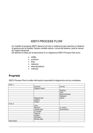
IDEF3 Process Flow ha delle informazioni associabili al diagramma nel suo complesso

Form 1
                               Scenario                        (nome)
                               Diagram status
                                                               Working
                                                               Draft
                                                               Recommended
                                                               Released
                               Diagram text                    (testo)
                               Used at
                               Project
Form 2
                               View
                               Revision                        (n. intero)
                               Update date                     (automatica)
                               C-number
                               Page No
                               Analyst
                               Reviewer
                               Review date
Swim lanes
Horizontal
                                Vertical
                                None


Poi ci sono informazioni correlate ad ognuna delle Swim Lanes:

Name
Definition
                                Descrizione
                                Ruoli                             Define
Symbol
                                Graphic Comment
DEFINIZIONI
               1. UOB’s (Units of Behaviour)

È un termine utilizzato per descrivere diversi tipi di “accadimenti”. Concetti come funzione,
processo, scenario, attività, operazione, decisione, azione, evento, procedura, ecc.,
rappresentano “accadimenti” che implicano una qualche forma di “comportamento”
(behaviour) circoscritto.

Description
                       Glossary Text              (testo)
Elaboration
                       Object                     Define v
                                                  Glossary Text            (testo)
                                                  Object Type
                                                                           Affected
                                                                           Agent
                                                                           Created
                                                                           Destroyed
                                                                           Participant
                       Facts                      Define v
                                                  Description
                       Constraints                Define v
                                                  Description
Project Planning
                       Tempo
                       Time Measure               Day, hr, min, …….
                       Fixed Time                 Yes/No
                       Budgeted Cost
                       Fixed Cost
                       Actual Cost
                       Milestone                  Yes/No
                       Summary Task               Yes/No
                       Priority                   High, low….
                       WBS Code
Matrices               (vedi Matrici)

Symbol
                       Graphic Comment
                       Number
                       IDEF Ref No.
2. Junction

È un elemento di un diagramma IDEF3 che identifica un “branch logico”.

Description
                        Glossary Text
Elaboration
                        Object                        Define v
                                                      Glossary Text    (testo)
                                                      Object Type
                                                                       Affected
                                                                       Agent
                                                                       Created
                                                                       Destroyed
                                                                       Participant
                        Facts                         Define v
                                                      Description
                        Constraints                   Define v
                                                      Description
Symbol
                        Graphic Comment
                        Number
                        Logic
                                                      And
                                                      OR
                                                      XOR
                        Timing
                                                      Synchronous
                                                      Asynchronous


              3. Link

È un elemento sintattico di un diagramma IDEF3 usato per connettere altri elementi del
diagramma. I links denotano le correlazioni significative tra UOB’s, object states e objects.
Esistono tre tipi di link:

              •   Precedence Link
              •   Relational Link
              •   Object Flow Link


3.1 Precedence Link

Rappresenta semplicemente una precedenza temporale tra l’attivazione (instance) di una
UOB e quella di un’altra.


Name
Description
                                      Glossary Text
Elaboration
Object                        Define v
                                                                Glossary Text
                                                                Object Type


                                  Facts                         Define v
                                                                Description
                                  Constraints                   Define v
Source&Destination Form
                                  From UOB                      (automatico)
                                  To UOB                        (automatico)
Symbol
                                  Graphic Comment


3.2 Relational Link -- (chiamato anche “user-defined link”)
Denota l’esistenza di una correlazione ”user-defined” tra due o più UOB’s. Vale la tabella
precedente.


3.3 Object Flow Link
Denota la presenza di un oggetto (object) nell’attivazione di due UOB’s e implica inoltre un
vincolo di precedenza.


Name
Description
                                  Glossary Text
Elaboration
                                  Object                        Define v
                                                                Glossary Text
                                                                Object Type


                                  Facts                         Define v
                                                                Description
                                  Constraints                   Define v
Source&Destination Form
                                  From UOB                      (automatico)
                                  To UOB                        (automatico)
Symbol
                                  Graphic Comment


              4. Referent
È un elemento di un diagramma IDEF3 usato per fare riferimento ad uno
scenario, una UOB o ad un “transition schematic”.
Name
Introduction
                   Referent Type
                                             Object
                                             OSTN
                                             Scenario
                                             UOB
                   Elab                      Define vv
                                             Description        Glossary Text
                                             Elaboration
                                                                Objects           Define
                                                                Facts             Define
                                                                Constraints       Define
                   Go-to UOB symbol
                   Junction                  Define
                   Note Text
                   IDEF3 Object
                   OSTN
                   IDEF3 Scenario            Define             Description       (testo)
                                                                Need              (testo)
                                                                Purpose           (testo)
                                                                Scope             (testo)
                                                                Time Frame
                                                                                  “As is/To be”
                   UOB                       Define
Symbol
                   Graphic Comment
                   Locator
                                             UOB Number
                                             Scenario Nr.
                                             OSTN Nr.
                   Timing
                                             Unconditional
                                             Synchronous
                                             Aynchronous
                   Attached to               (automatic)


               5. Decomposition

Decomposition is the act of breaking a system into its component subsystems, processes,
and sub-processes. Each level of abstraction reveals more or less detail about the overall
system.


               6. Matrici
Name
Matrices
                Applications
                                   Introduction
                                                      Description
                                                      Related EBP ‘s
                                   Technologies       Define           (dimmed)
                                   Application Type
Application Type (testo)
                                              Application      Define >>    (vedi
                                              Sub-Type                      Applications)
                               Application    Define vv
                               Interfaces
                                              Interfaces
                                              Interface
                                              Definition


  IDEF3 Object State Transition Network (OSTN Diagrams)
An Object State Transition Network (OSTN) diagram is used to model the behavior of an
object as it transitions from state to state, based on events. You may specify what object
the OSTN diagram shows behavior for, in the OSTN diagram properties.


Proprietà
La tabella seguente illustra le proprietà associate al diagramma stesso:
Description
              Scenario         Define vv
                               Description     (testo)
                               Need            (testo)
                               Purpose         (testo)
                               Scope           (testo)
                               Time Frame      “As is/To be”
              Object           Define vv
                               Glossary Text
                               Object Type
                                               Affected
                                               Agent
                                               Created
                                               Destroyed
                                               Participant
              OSTN Glossary
Form 1
              Diagram Status
                               Working
                               Draft
                               Recommended
                               Released
              Used At
              Project
              View
              Revision
              UpdateDate       (automatic)
Form 2
              View
              Revision         (n. intero)
              Update date      (automatica)
              C-number
              Page No
              Analyst
              Reviewer
              Review date
OSTN
Elaboration
                   OSTN Set         (IDEF3 OST’s)
                   Scenario Set     (IDEF3 Process
                                    Flow’s)
                   Object State Set (States)               Define >>           (vedi “State”)
                   UOB Set          (UOB’s)                Define >>           (vedi “UOB”)


              1. Transitions (Dictionary Object)

Transitions represent allowable changes between states. One of the first steps in the
development of an Object State Transition Network (OSTN) is to identify all possible states
in which the object can exist. Though a real-world object often evolves through a
continuum of states, an OSTN diagram focuses on those distinguished states that are of
particular interest to the domain expert. For each of these states, the OSTN diagram
supports the specification of:
   •   the conditions that characterize the state
   •   the conditions that will permit a transition into the state (entry conditions)
   •   the conditions that need to hold for the object to transition out of the state (exit
       conditions
2. State (Model object)
Name
Introduction
                   Description
                   Object Name     Define >>        Glossary Text
                                                    Object Type
                                                                    Affected
                                                                    Agent
                                                                    Created
                                                                    Destroyed
                                                                    Participant
Object State Set Define
Entry Conditions
Sets
                 Entry From State (State)           Define
                 Entry From       (Fact)            Define
                 Facts
                 Entry From       (Constraint)      Define
                 Constraints
                 State
                 Descriptiom
                 Conditions
                                  Facts             (Fact)          Define
                                  Constraints       (Constraint)    Define
                 Exit Conditions
                 Set
                                  Exit To State     (State)         Define
                                  Exit To facts     (Fact)          Define
                                  Exit To           (Constraint)    Define
                                  Constraints
Symbol           Graphic
                 Description


               3. Transition Arrow (Model Object)

                      Name
                      Definition      Description
                      Symbol          Graphic
                                      Comment
Sa2001 idef3
Sa2001 idef3

Mais conteúdo relacionado

Mais de Arnaldo Colombo

Mais de Arnaldo Colombo (19)

Value Reference Model - Sales
Value Reference Model - SalesValue Reference Model - Sales
Value Reference Model - Sales
 
Value Reference Model - Supply Chain
Value Reference Model - Supply ChainValue Reference Model - Supply Chain
Value Reference Model - Supply Chain
 
Value Reference Model - Development
Value Reference Model - DevelopmentValue Reference Model - Development
Value Reference Model - Development
 
Value Reference Model - Executing
Value Reference Model - ExecutingValue Reference Model - Executing
Value Reference Model - Executing
 
Value Reference Model - Enterprise Architecture
Value Reference Model  - Enterprise ArchitectureValue Reference Model  - Enterprise Architecture
Value Reference Model - Enterprise Architecture
 
Value Reference Model - Governing
Value Reference Model - GoverningValue Reference Model - Governing
Value Reference Model - Governing
 
Value Reference Model - Planning
Value Reference Model - PlanningValue Reference Model - Planning
Value Reference Model - Planning
 
Factory control system
Factory control systemFactory control system
Factory control system
 
Versions management
Versions managementVersions management
Versions management
 
Qualità dei documenti
Qualità dei documentiQualità dei documenti
Qualità dei documenti
 
Innovazione
InnovazioneInnovazione
Innovazione
 
Idef3
Idef3Idef3
Idef3
 
Idef0
Idef0Idef0
Idef0
 
Idef0
Idef0Idef0
Idef0
 
Sa framework
Sa frameworkSa framework
Sa framework
 
Quality Function Deployment
Quality Function DeploymentQuality Function Deployment
Quality Function Deployment
 
Business Modeling
Business ModelingBusiness Modeling
Business Modeling
 
Balanced Scorecards
Balanced ScorecardsBalanced Scorecards
Balanced Scorecards
 
Business Process Modeling
Business Process ModelingBusiness Process Modeling
Business Process Modeling
 

Sa2001 idef3

  • 1. IDEF3 PROCESS FLOW Un modello di processo IDEF3 descrive ciò che un sistema fa (per esempio un Sistema di gestione per la Qualità). Questo modello cattura I vincoli del sistema, quali le risorse ed i legami temporali. Gli elementi di base per la descrizione di un diagramma IDEF3 Process Flow sono: • UOBs • junctions • links • referents • decompositions • matrices Proprietà IDEF3 Process Flow ha delle informazioni associabili al diagramma nel suo complesso Form 1 Scenario (nome) Diagram status Working Draft Recommended Released Diagram text (testo) Used at Project Form 2 View Revision (n. intero) Update date (automatica) C-number Page No Analyst Reviewer Review date Swim lanes
  • 2. Horizontal Vertical None Poi ci sono informazioni correlate ad ognuna delle Swim Lanes: Name Definition Descrizione Ruoli Define Symbol Graphic Comment DEFINIZIONI 1. UOB’s (Units of Behaviour) È un termine utilizzato per descrivere diversi tipi di “accadimenti”. Concetti come funzione, processo, scenario, attività, operazione, decisione, azione, evento, procedura, ecc., rappresentano “accadimenti” che implicano una qualche forma di “comportamento” (behaviour) circoscritto. Description Glossary Text (testo) Elaboration Object Define v Glossary Text (testo) Object Type Affected Agent Created Destroyed Participant Facts Define v Description Constraints Define v Description Project Planning Tempo Time Measure Day, hr, min, ……. Fixed Time Yes/No Budgeted Cost Fixed Cost Actual Cost Milestone Yes/No Summary Task Yes/No Priority High, low…. WBS Code Matrices (vedi Matrici) Symbol Graphic Comment Number IDEF Ref No.
  • 3. 2. Junction È un elemento di un diagramma IDEF3 che identifica un “branch logico”. Description Glossary Text Elaboration Object Define v Glossary Text (testo) Object Type Affected Agent Created Destroyed Participant Facts Define v Description Constraints Define v Description Symbol Graphic Comment Number Logic And OR XOR Timing Synchronous Asynchronous 3. Link È un elemento sintattico di un diagramma IDEF3 usato per connettere altri elementi del diagramma. I links denotano le correlazioni significative tra UOB’s, object states e objects. Esistono tre tipi di link: • Precedence Link • Relational Link • Object Flow Link 3.1 Precedence Link Rappresenta semplicemente una precedenza temporale tra l’attivazione (instance) di una UOB e quella di un’altra. Name Description Glossary Text Elaboration
  • 4. Object Define v Glossary Text Object Type Facts Define v Description Constraints Define v Source&Destination Form From UOB (automatico) To UOB (automatico) Symbol Graphic Comment 3.2 Relational Link -- (chiamato anche “user-defined link”) Denota l’esistenza di una correlazione ”user-defined” tra due o più UOB’s. Vale la tabella precedente. 3.3 Object Flow Link Denota la presenza di un oggetto (object) nell’attivazione di due UOB’s e implica inoltre un vincolo di precedenza. Name Description Glossary Text Elaboration Object Define v Glossary Text Object Type Facts Define v Description Constraints Define v Source&Destination Form From UOB (automatico) To UOB (automatico) Symbol Graphic Comment 4. Referent È un elemento di un diagramma IDEF3 usato per fare riferimento ad uno scenario, una UOB o ad un “transition schematic”.
  • 5. Name Introduction Referent Type Object OSTN Scenario UOB Elab Define vv Description Glossary Text Elaboration Objects Define Facts Define Constraints Define Go-to UOB symbol Junction Define Note Text IDEF3 Object OSTN IDEF3 Scenario Define Description (testo) Need (testo) Purpose (testo) Scope (testo) Time Frame “As is/To be” UOB Define Symbol Graphic Comment Locator UOB Number Scenario Nr. OSTN Nr. Timing Unconditional Synchronous Aynchronous Attached to (automatic) 5. Decomposition Decomposition is the act of breaking a system into its component subsystems, processes, and sub-processes. Each level of abstraction reveals more or less detail about the overall system. 6. Matrici Name Matrices Applications Introduction Description Related EBP ‘s Technologies Define (dimmed) Application Type
  • 6. Application Type (testo) Application Define >> (vedi Sub-Type Applications) Application Define vv Interfaces Interfaces Interface Definition IDEF3 Object State Transition Network (OSTN Diagrams) An Object State Transition Network (OSTN) diagram is used to model the behavior of an object as it transitions from state to state, based on events. You may specify what object the OSTN diagram shows behavior for, in the OSTN diagram properties. Proprietà La tabella seguente illustra le proprietà associate al diagramma stesso:
  • 7. Description Scenario Define vv Description (testo) Need (testo) Purpose (testo) Scope (testo) Time Frame “As is/To be” Object Define vv Glossary Text Object Type Affected Agent Created Destroyed Participant OSTN Glossary Form 1 Diagram Status Working Draft Recommended Released Used At Project View Revision UpdateDate (automatic) Form 2 View Revision (n. intero) Update date (automatica) C-number Page No Analyst Reviewer Review date
  • 8. OSTN Elaboration OSTN Set (IDEF3 OST’s) Scenario Set (IDEF3 Process Flow’s) Object State Set (States) Define >> (vedi “State”) UOB Set (UOB’s) Define >> (vedi “UOB”) 1. Transitions (Dictionary Object) Transitions represent allowable changes between states. One of the first steps in the development of an Object State Transition Network (OSTN) is to identify all possible states in which the object can exist. Though a real-world object often evolves through a continuum of states, an OSTN diagram focuses on those distinguished states that are of particular interest to the domain expert. For each of these states, the OSTN diagram supports the specification of: • the conditions that characterize the state • the conditions that will permit a transition into the state (entry conditions) • the conditions that need to hold for the object to transition out of the state (exit conditions
  • 9. 2. State (Model object) Name Introduction Description Object Name Define >> Glossary Text Object Type Affected Agent Created Destroyed Participant Object State Set Define Entry Conditions Sets Entry From State (State) Define Entry From (Fact) Define Facts Entry From (Constraint) Define Constraints State Descriptiom Conditions Facts (Fact) Define Constraints (Constraint) Define Exit Conditions Set Exit To State (State) Define Exit To facts (Fact) Define Exit To (Constraint) Define Constraints Symbol Graphic Description 3. Transition Arrow (Model Object) Name Definition Description Symbol Graphic Comment