SlideShare uma empresa Scribd logo
1 de 17
Baixar para ler offline
VIRTUAL OUTRIGGERS IN TALL BUILDINGS
Andrew J. Horton
ABSTRACT: As stated by Nair (1998) the conventional outrigger concept is in widespread use
today in the design of tall buildings. In this concept, outrigger trusses (or, occasionally, girders)
extend from a lateral load-resisting core to columns at the exterior of the building (see Stafford
Smith and Coull 1991). It is, in its simplest form, a one-stage, 2-D (planar) concept in the
vertical plane. The core may consist of either shear walls or braced frames. Conventional
outrigger systems can lead to very efficient use of structural materials by mobilizing the axial
strength and stiffness of exterior columns to resist part of the overturning moment produced by
lateral loading. There are, however, some important space-planning limitations and certain
structural complications associated with the use of conventional outriggers in tall buildings. A
variation on the conventional outrigger concept is the offset outrigger concept and associated
alternative offset outrigger concept (see Stafford Smith, Cruvellier, Nollet & Mahyari 1996).
These are, in their simplest forms, two-stage, 2-D concepts, with the first stage in the horizontal
plane and the second in the vertical plane. Offset and alternative offset outriggers can overcome
or circumvent many of the problems associated with conventional outriggers. The alternative
offset outrigger concept was “re-branded” by Nair (1998) as the “virtual outrigger concept”
with respect to the use of belt trusses and belt walls as alternative offset outrigger elements.
This was again a two-stage, 2-D concept, first in the horizontal plane and then in the vertical
plane. He did however introduce a more specialized development of the alternative offset
outrigger concept – the design philosophy of which the present author considers to be a more
fitting definition of the virtual outrigger concept – in the use of basement walls as virtual
outriggers for tall buildings. This is first a 2-D concept in the horizontal plane (via floor
diaphragms) and then a 3-D concept in the vertical plane (transferring the resultant loadings to
the basement end walls and their foundation systems – through their connection to the basement
side walls – as well as to the basement side walls and their foundation systems). The
application of Nair’s virtual outrigger concept for basement walls, as described above, is
applied to continuous, perimeter belt trusses or belt walls at outrigger levels in this paper.
KEY WORDS: conventional outrigger concept; outrigger trusses; offset outrigger concept;
alternative offset outrigger concept; belt trusses; belt walls; virtual outrigger concept
1. BACKGROUND & INTRODUCTION
According to Stafford Smith et al (1996), at the time of writing their paper introducing the offset
outrigger and alternative offset outrigger concept, the conventional outrigger concept had already
been in use in the design of tall buildings for 30 years.
The present author investigated the 10 tallest skyscrapers either completed or expected to be
completed in 2010 and discovered that the 7 tallest, along with the 10th
tallest, all incorporate the
conventional outrigger concept as an integral part of their design, Table 1.
The 8th
tallest, Willis Tower (formerly Sears Tower) was completed in 1973 and utilized a
bundled tube system of construction stepping from 9 bundles at the base to 2 bundles at the top,
Figure 1.
The 9th
tallest, Guangzhou West Tower (still under construction) is utilizing a twin tube system
of construction with the outer tube (perimeter) being comprised of a diagonal grid (diagrid) of
1600 mm diameter concrete filled tubes with ring beams linked back to the inner tube (core) with
tie beams, Figure 2.
Table 1: Usage of Conventional Outrigger Concept in Ten Tallest Skyscrapers
# Building City Country Height
(m)
Floors Completed # of
Outrigger
Levels
1 Burj Khalifa Dubai UAE 828 160 2010 5
2 Taipei 101 Taipei Taiwan (ROC) 509 101 2004 11
3 Shanghai World Financial Centre Shanghai China (PRC) 492 101 2008 8
4 International Commerce Centre Kowloon Hong Kong 483 118 2010
(Expected)
4
5 Petronas Tower 1 Kuala
Lumpur
Malaysia 452 88 1998 1
6 Petronas Tower 2 Kuala
Lumpur
Malaysia 452 88 1998 1
7 Nanjing Greenland Financial Centre Nanjing China (PRC) 450 89 2010
(Expected)
3
8 Willis Tower
(formerly Sears Tower)
Chicago USA 442 108 1973 0
9 Guangzhou West Tower Guangzhou China (PRC) 440 103 2010
(Expected)
0
10 Trump International Hotel and Tower Chicago USA 423 96 2010 3
Figure 1: Willis Tower, Chicago, USA Figure 2: Guangzhou West Tower,
Guangzhou, China
The present author also conducted an investigation to ascertain the usage of the offset outrigger,
alternative offset outrigger and virtual outrigger concepts in approved or completed tall buildings
to date, Table 2.
Table 2: Usage of Offset, Alternative Offset or Virtual Outrigger Concept in
Approved or Completed Tall Buildings
# Building City Country Height
(m)
Floors Approved /
Completed
# of Outrigger Levels
1 Dubai Tower
Doha
Doha Qatar 438 90 Approved /
Partially Completed /
On Hold
3
(1 Conventional; 2
Mixed Conventional /
Alternative Offset)
2 Plaza Rakyat
Office Tower
Kuala
Lumpur
Malaysia 382 79 Approved /
Partially Completed /
On Hold
3
(1 Conventional; 2
Virtual)
3 Aston
Apartments
Residential
Tower
Sydney Australia 90 30 1998 2
(1 Alternative Offset; 1
Mixed Offset/Alternative
Offset)
A relative dearth of information is available in the literature regarding the offset, alternative
offset and virtual outrigger concepts compared to a relative wealth of information regarding the
conventional outrigger concept. The following discussion, after laying the ground work for an
understanding of the conventional, offset and alternative offset outrigger concepts, seeks to
elaborate further on the use of belt trusses and belt walls, as virtual outriggers in tall buildings.
2. DISCUSSION
2.1 Conventional Outrigger Concept
2.1.1 Explanation
Stafford Smith et al (1996) stated that up until that point in time, the outrigger concept, speaking
of the conventional outrigger system, had been governed mainly by a planar conceptualization of
the interactions between the core walls, the outrigger arms and the exterior columns.
Summarizing the functioning of this system, in its simplest form, they stated, that when lateral
loading acts along the plane of the outrigger bent, the bending of the core rotates the stiff
outrigger arms that cantilever from it, inducing tension in the upwind column and compression in
the downwind column. These column forces, acting at the extremities of the outrigger arms,
form a couple that restrains the bending and deflection of the core, Figure 3 (taken from Stafford
Smith and Coull 1991).
Stafford Smith and Coull (1991) stated that in addition to those columns located at the ends of
the outriggers, it is usual to also mobilize other peripheral columns to assist in restraining the
outriggers. This is achieved by including a deep spandrel girder, or “belt” truss, around the
structure at the levels of the outriggers, hence the name, “belt-braced structure”, Figure 4. The
present author also makes use of this technique in § 2.3.1, § 2.3.3 and Appendix A of this paper.
Figure 3 (a): Outrigger Structure Displaced under Lateral Loading,
(b): Resultant Deflections and (c): Resultant Core Moments.
Figure 4: Conventional Outrigger Structure with Belt Girders
The large, often two-storey, depths of the outrigger and perimeter trusses make it desirable to
locate them within the plant levels of the building.
Stafford Smith and Coull (1991) further stated that the degree to which the perimeter columns of
an outrigger structure behave compositely with the core depends on the number of levels of
outriggers and their stiffness. Multilevel outrigger structures show a considerable increase in
their effective moment of resistance over single level outrigger structures. Each additional level
of outriggers increases the lateral stiffness, but by a smaller amount than the previous additional
level with four or five levels appearing to be the economic limit for a tall building. They found
that in any outrigger system it is, perhaps unexpectedly, structurally inefficient to locate an
outrigger level at the top of the building and that this should only be undertaken when dictated
by other constraints, e.g. a plant floor needing to be located at the top of the building.
By making the necessary simplifying assumptions, i.e. the structure is linearly elastic, only axial
forces are induced in the columns, the outriggers are rigidly attached to the core, the core is
rigidly attached to the foundation, the sectional properties of the core, columns and outriggers are
uniform throughout their height and expressing the applied lateral load as a uniformly distributed
horizontal load over the full height of the building, Stafford Smith and Coull (1991) used
established structural theory, i.e. the moment area method, the moment equation for a vertical
cantilever, the deflection equation for a vertical cantilever and various axial and flexural stiffness
representations, to develop charts expressing the optimum location of outriggers, for an n-
outrigger system (where 1 < n < 4), to minimise top of structure lateral deflections.
Generally, by making a further (hypothetical) simplifying assumption, i.e. that the outriggers are
flexurally rigid, they found, for the optimum performance of an n-outrigger structure, that the
outriggers should be placed at the 1/(n+1), 2/(n+1), up to the n/(n+1) height locations, i.e. for a
one-outrigger structure at approximately half-height, for a two-outrigger structure at
approximately one-third and two-thirds heights, for a three-outrigger structure at approximately
one-quarter, one-half and three-quarter heights, and so on. The present author comments that
these findings also hold true for the subsequently discussed offset, alternative offset and virtual
outrigger systems under similar simplifying assumptions.
It should be noted that the optimum outrigger arrangement for the maximum reduction in drift
was not found to simultaneously cause the maximum reduction in the core base moment. For
this, the outriggers would have to be lowered toward the base. It was suggested in cases where
drift control is not critical, that the design emphasis could change to controlling the core
moments by lowering the heights of the outrigger levels from the base until the drift limitations
are just satisfied but noted, due to other constraints, that this might only be achievable in reality.
Wu and Li (2003) followed up on the above optimum outrigger arrangement work by Stafford
Smith and Coull (1991) for the case where the applied lateral load is modelled as both a
triangular and uniformly distributed horizontal load over the full height of the building. They
found when an outrigger-braced structure is subjected to horizontal triangular loads, the optimum
locations of outriggers are 4 – 5% higher than those of the structure subjected to horizontal
uniform load. In lieu of any further investigation their findings could be used to give a
conservative upper bound for optimum outrigger positions under horizontal trapezoidal loading.
While the conventional outrigger system is very effective in increasing the structures flexural
stiffness, it does not increase its resistance to shear, which has to be carried mainly by the core
(Stafford Smith and Coull 1991). The present author comments that this principle also holds true
for the subsequently discussed offset, alternative offset and virtual outrigger systems.
2.1.2 Examples
The 492 m height, 101 floors, Shanghai World Financial Centre, designed by Leslie E.
Robertson Associates, completed in 2008 in China, has 8 conventional outrigger levels, Figure 5.
Figures 5 (a) and (b): Model showing the
Building’s Mega-Structure System of
Mega-Columns, Diagonals and Belt
Trusses along with Concrete Core
Walls and Outrigger Trusses
Figure 5 (c): Tie Columns, Diagonals,
Belt Trusses and Outrigger Trusses
Connected to the Concrete
Shear Walls of the
Service Core
The 450 m height, 89 floors, Nanjing Greenland Financial Centre, designed by Skidmore,
Owings and Merrill (SOM), presently under construction in China, has 3 conventional outrigger
levels, Figure 6.
Figure 6 (a): Outrigger and Belt Truss Configuration, (b): Typical Outrigger Truss –
Continuous through Core and (c): Photograph of Outrigger Truss Construction
The 360 m height, 93 floors, Federation Tower, Tower A, designed by Thornton Tomasetti,
presently under construction in Moscow, Russia, has 2 conventional outrigger levels, Figure 7.
Figure 7 (a): Model of
61st
Floor Outrigger
Level
Figure 7 (b): 33rd
Floor Outrigger
Trusses linking the Belt Trusses
(Left) to the Central Core
2.2 Offset and Alternative Offset Outrigger Concepts
2.2.1 Explanation
Stafford Smith et al (1996) proposed that the outriggers may be located elsewhere than in the
planes of the core walls, while retaining all the advantages and mitigating some of the
disadvantages of the conventional outrigger system. They proposed to move, or offset, the
outrigger arms horizontally within the floor plan, away from the central elevator core, Figure 8.
Detailed structural analysis conducted on buildings incorporating such laterally shifted outriggers
indicated that, compared to the conventional arrangement – Figure 8 (b) – the offset outrigger
concept – Figure 8 (c) – as defined above and compared with the conventional outrigger system,
was virtually 100% effective in reducing the building deflections and the core bending stresses
resulting from centred wind or earthquake loading (Stafford Smith et al 1996).
Moreover, for typical floor slab plan dimensions and thicknesses, they discovered that there was
little reduction in the effectiveness of the offset outrigger as it is shifted further from the central
core – becoming the alternative offset concept, as represented in Figure 8 (d).
For the offset outrigger system to work, it is essential that the floor slabs be effectively rigid and
strong enough in their planes to transfer the horizontal plane shears between the outrigger arm
and the core. For typical residential and office floor layouts, the slabs will be thick enough and
the building dimensions will be sufficient to ensure that this condition is easily met (Stafford
Smith et al 1996).
They further noted that it is also necessary for the outrigger arm to be as rigid as possible in
flexure across the width of the building (similar to the stiffness requirement for the conventional
outrigger). In both cases – offset and alternative offset – there are many ways to achieve
adequate stiffness, be it with diagonal bracing (belt trusses) or reinforced concrete in-filled
panels (belt walls). Just as in the case of the conventional outrigger system, the outrigger arm in
the offset system may also be spread vertically over several stories in order to reduce the
obstruction at any individual floor level.
Stafford Smith et al (1996) also alluded to studies indicating potentially significant structural
benefits arising from the offset outrigger system in terms of the building’s torsional response to
off centre loading. The maximum benefit was reported to be obtained by offsetting the
outriggers on plan as far as possible from the centre of rotation of the building, i.e. to the
perimeter.
With the addition of a full-depth of outrigger level, continuous, perimeter belt truss or belt walls
to the two remaining horizontal sides of Figure 8 (d) the alternative offset outrigger concept
would match the definition provided by the present author of the virtual outrigger concept stated
in § 2.3.1 of this paper.
Figure 8 (a): Typical Floor Plan Figure 8 (b): Conventional Outrigger
Plan
Figure 8 (c): Offset Outrigger Plan Figure 8 (d): Alternative Offset Outrigger
Plan
In summary the case was made by Stafford Smith et al (1996) that, in terms of structural
efficiency, nothing is lost by laterally offsetting outriggers from the plane of the central core
walls and that a considerable advantage of this new configuration is greater flexibility of the
building floor plan to met functional and aesthetic design requirements.
The relevant load transfer mechanism for the alternative offset outrigger concept shown below in
Figure 9 is fully explained in Stafford Smith et al (1996).
Figure 9 (a): Axonometric View Figure 9 (b): Relative Displacements of
Slabs considering only the Core Wall
Figure 9 (c): Outrigger subject to
Couple from Slabs
Figure 9 (d): Restraining Couple from
Perimeter Columns
Figure 9 (e): Restraining Couple from Perimeter Columns
back through Slabs to Core
2.2.2 Example
The 90m height, 30 floors, Aston Apartments Residential Tower, designed by Connell Wagner,
completed in 1998 in Sydney, Australia, has 1 alternative offset outrigger level (roof) and 1
mixed offset and alternative offset outrigger level (mid-height), Figure 10 (taken from Dean,
Martin, Emery and Chancellor 2001).
The reinforced concrete frame structure with central lift core – quoted as being the first “offset
outrigger” building in Australasia – is only 13m wide in the North-South direction resulting in a
slender height-to-base ratio of 7:1. The “offset outriggers” – comprising of two storey high shear
walls 200 mm thick – significantly reduce building deflections and core bending moments. Core
wall thicknesses were able to be limited to 200 mm even in the lower levels (Dean et al 2001).
Figure 10: Frame Perspective – Aston Apartments Residential Tower
2.3 Virtual Outrigger Concept
2.3.1 Explanation
Following on from Stafford Smith et al (1996), Nair (1998) coined the phrase “virtual”
outriggers to refer to a subset of offset outriggers, previously termed alternative offset outriggers,
which were to be located only at the perimeter of the building and which were not to be directly
attached to the core, stating that belt trusses and belt walls were well suited for use as “virtual”
outriggers. A close investigation, however, of Nair (1998) reveals that, with respect to the belt
trusses (or belt walls) at outrigger level, Nair was not considering that the belt trusses (or belt
walls) in the plane perpendicular to the action of lateral load could also be mobilised to distribute
the resultant tensile and compressive “stresses”, refer to Figure 12 below, to all of the perimeter
columns, refer also to § 2.3.3 and Appendix A.
Nair (1998) also used the phrase to refer to a “more specialized development” of the alternative
offset outrigger concept – the design philosophy of which the present author considers to be a
more fitting definition of the virtual outrigger concept – in the use of basement walls as “virtual”
outriggers for tall buildings.
This is first a 2-D concept in the horizontal plane (via floor diaphragms) and then a 3-D concept
in the vertical plane (transferring the resultant loadings to the basement end walls and their
foundation systems – through their connection to the basement side walls – as well as to the
basement side walls and their foundation systems), Figure 11 (taken from Nair 1998).
Figure 11. Force Transfer using Basement as Virtual Outrigger System
For the purpose of this paper, the present author would like to define the virtual outrigger
concept as being where belt trusses or belt walls are provided, full depth, continuously, around
the perimeter of an outrigger level – in a square or appropriately proportioned rectangular on
plan building – and act, together with the top and bottom structural diaphragm of the outrigger
level, to transfer substantially the same magnitude of overturning moment from the core to the
perimeter columns – engaging axially all of the perimeter columns – as could realistically be
achieved via the use of conventional outriggers.
Leonard (2007), speaking with reference to framed tube structures but equally applicable to
virtual outrigger structures, stated that shear lag effects can be reduced by employing additional
structural systems which increase the stiffness of the overall structural system, Figure 12.
He further stated that belt trusses effectively increase the shear stiffness of framed tube structures
by integrating all the columns in the same face of the building. He additionally stated that belt
trusses can also be added at multiple levels of a framed tube system. He finally stated that one of
the ideas similar to the belt truss system was the offset outrigger system proposed by Stafford
Smith et al (1996) and Nair (1998).
Figure 12: Axial Stress Distribution in Box Structure:
(a) Without Shear Lag and (b) With Shear Lag
If the stiffness of the belt truss or belt wall system in the virtual outrigger concept defined by the
present author can cause the axial loads on the “flange” perimeter columns to approach what is
depicted in Figure 12 (a) above then the capability of the system would better any conventional
outrigger system which did not have a belt truss or belt wall system sufficient to spread axial
loads along the “flange” and rival any conventional outrigger system which did.
2.3.2 Example
The 382 m height, 79 floors, Plaza Rakyat Office Tower, designed by SOM, construction
commenced circa 1996, stalled due to the 1997 Asian Financial Crisis and presently still on hold
in Kuala Lumpur, Malaysia, has 1 conventional outrigger level at roof height and two virtual
outrigger levels, Figure 13. Further information is available in Baker, Brown and Sinn (1997).
Figure 13: Model of Plaza Rakyat Office Tower (taken from SOM)
2.3.3 Finite Element Model (FEM) Investigation
A FEM was prepared for purpose of comparison with the results stated by Nair (1998) for his
example “75-story steel framed office tower”. The present author noted that the chamfered
corners in plan and light bracing in elevation adopted by Nair around these chamfered corners
effectively inhibited the full potential of the virtual outrigger concept, as defined by the present
author, from being realised. The FEM prepared removed the chamfers, placed “super-columns”
at the corners and continued the belt truss bracing around the entire outrigger level. Apart from
this modification the FEM compared “apples with apples” based on Nair’s provided information.
With the above modification the present author discovered that the onerous and inhibitive
measures proposed by Nair as being necessary to “match” the performance of a conventional
outrigger system were no longer required. In summary, a 2-fold increase in outrigger diaphragm
thicknesses (not a 10-fold increase in stiffness as proposed by Nair) coupled with a 16% increase
in belt truss area (not 10-fold increase in stiffness as proposed by Nair) sufficed to enable the
virtual outrigger system to perform within 4% of the lateral deflection capacity achieved by the
conventional outrigger system.
Concrete belt walls were also substituted for the steel belt trusses at outrigger levels to good
effect in the FEM and an alternative reinforced concrete structure was also modelled with virtual
versus conventional outrigger performance compared.
The results of the FEM investigation are included in Appendix A.
3. SUMMARY & CONCLUSION
The virtual outrigger system, as defined by the present author, is found to be capable of
providing comparable performance to the conventional outrigger system.
The virtual outrigger system thus employed would eliminate the need to attach outrigger
members to the core for square or appropriately proportioned rectangular on plan buildings.
Additionally, when utilizing the virtual outrigger system, outrigger levels could be placed at
optimum levels up the height of the building, as the virtual outrigger members, i.e. belt trusses or
belt walls, are positioned on the perimeter of the building.
Furthermore, the adoption of the virtual outrigger system, with its full depth, continuous,
perimeter belt trusses or belt walls at outrigger levels would result in a reduction in potential
“shear lag” type effects in the perimeter columns of the building.
Finally, the virtual outrigger system would also dually offer the building enhanced torsional
resistance and reduced susceptibility to the differential shortening effects encountered by the
conventional outrigger system.
REFERENCES
Baker, W. F., Brown, C. D. and Sinn, R. C. (1997). Structural Analysis and Design of the World’s
Tallest Reinforced Concrete Building. E & FN Spon. Multi-Purpose High-Rise Towers and Tall
Buildings, 333–346.
Dean, B., Martin, O., Emery, D. and Chancellor, P. (2001). Tall Building Design Innovations in
Australia. Tall Buildings and Urban Habitat, Cities in the Third Millennium, 6th
World Congress of
the Council On Tall Buildings and Urban Habitat, Melbourne, 26 February to 2 March 2001.
Planning and Architecture, 393–394.
Leonard, J. (2007) Investigation of Shear Lag Effect in High-Rise Buildings with Diagrid Systems.
Degree of Master of Engineering in Civil and Environmental Engineering. Department of Civil and
Environmental Engineering, Massachusetts Institute of Technology.
Nair, R. Shankar (1998) Belt Trusses and Basements as “Virtual” Outriggers for Tall Buildings.
American Institute of Steel Construction. Engineering Journal, Fourth Quarter, 140–146.
Stafford Smith, B. and Coull, A. (1991) Tall Building Structures: Analysis and Design. John Wiley and
Sons, Inc. Chapter 14, Outrigger-Braced Structures, 355–371.
Stafford Smith, B., Cruvellier, M., Nollet, M-J. and Mahyari, A. T. (1996) Offset Outrigger Concept for
Tall Building Structures. Council on Tall Buildings and Urban Habitat. Tall Building Structures – A
World View, 73–80.
Wo J. R. and Li, Q. S. (2003) Structural Performance of Multi-Outrigger-Braced Tall Buildings.
Published online in Wiley InterScience (www.interscience.wiley.com). DOI:10.1002/tal.219. The
Structural Design of Tall and Special Buildings 12, 155–176.
ABOUT THE AUTHOR
Andrew J. Horton, BE(Hons), MIPENZ(Structural), CPEng, IntPE(NZ), Structural Design Manager,
Hyder Consulting Middle East Ltd, Global Design Centre – Manila, Philippines.
Email: andrew.horton@hyderconsulting.com.
ACKNOWLEDGEMENTS
Francis O. Macatingrao, B.S. C.E., Graduate Structural Engineer and Carlos Alfonso V. Fabie, B.S. C.E.,
Assistant Structural Engineer, Hyder Consulting Middle East Ltd, Global Design Centre – Manila,
Philippines. Email: francis.macatingrao@hyderconsulting.com and carlos.fabie@hyderconsulting.com.
Milan Petrovic, dipl.inž., Senior Structural Engineer, Hyder Consulting Middle East Ltd, Dubai, UAE.
Email: milan.petrovic@hyderconsulting.com.
Marie-José Nollet, ing., Ph.D., Département de génie de la construction, École de technologie supérieure,
1100, rue Notre-Dame ouest, Montréal, Qc, H3C 1K3, Canada. Email: marie-jose.nollet@etsmtl.ca.
APPENDIX A
STEEL FEM SUMMARY
Ratio of Lateral Displacement at Top for Outrigger Type i
Versus
Lateral Displacement at Top without Outriggers
(SLS Wind)
Type of Outrigger
From Present FEM Analysis From Literature
(%) (%)
Conventional Outrigger 22.2 23.3
Belt Truss as Virtual Outrigger 25.7 34.2
Ratio of Σ Total Outrigger Moment Type i at Base
Versus
Σ Total Moment at Base
Type of Outrigger
From Present FEM Analysis
(%)
Conventional Outrigger 56.9
Belt Truss as Virtual Outrigger 52.0
As shown in the following table, in the Steel FEM Analysis an equivalent 100mm thick continuous perimeter concrete
belt wall may be used to replace the above continuous perimeter steel belt truss system – holding everything else
constant – to achieve the same lateral performance. Moreover, the performance of the structure may be further
enhanced by thickening these concrete belt walls.
Using Concrete Belt Walls as Virtual Outriggers
Thickness
Lateral Displacement at
Top due to SLS Wind (m)
Reduction in Lateral Displacement
at Top compared with Steel Belt
Truss (%)
100mm 0.620 0.9
200mm 0.565 8.6
300mm 0.543 13.0
CONCRETE FEM SUMMARY
Type of Outrigger
Ratio of Lateral Displacement at Top for Outrigger Type i
Versus
Lateral Displacement at Top without Outriggers
(SLS Wind)
(%)
Conventional Outrigger 29.2
Belt Wall as Virtual Outrigger 27.2
Type of Outrigger
Ratio of Σ Total Outrigger Moment Type i at Base
Versus
Σ Total Moment at Base
(%)
Conventional Outrigger 54.0
Belt Truss as Virtual Outrigger 52.0
MODELLING ASSUMPTIONS
1. The structural diaphragms were assumed to have no out of plane stiffness.
2. SLS Wind Combinations and Wind Loads were as per ASCE 7-05 code provisions.
ADDITIONAL FEM ANALYSIS
Subsequent modifications to the steel belt truss system were performed in the Steel FEM in order to achieve the
same lateral performance as the conventional outrigger system. This is summarized in the tables below.
Before any modifications were made the following table shows the results:
Type of Outrigger
Lateral Displacement at Top due to
SLS Wind
(m)
Without Outrigger 2.386
Conventional Outrigger 0.529
Virtual Outrigger 0.614
The ratio of virtual outrigger to conventional outrigger displacement is approx 16.1%.
The following modifications were then made to the steel beam truss virtual outrigger system:
Modifications to Belt Truss System
(Normal-Weight Concrete)
SLS Deflection
(m)
Comparison to Performance of
Conventional Outrigger
(% Difference)
1.6 x Increase in Outrigger Diaphragm Thicknesses 0.599 13.2
2.0 x Increase in Outrigger Diaphragm Thicknesses 0.592 11.9
Increase Bracing Size in Belt Trusses from W14x730 to
W36x848 (Increase in Area by 15.8%) without Increasing
Outrigger Diaphragm Thicknesses
0.593 12.1
Combined 2.0 x Increase in Outrigger Diaphragm
Thicknesses and Increase in Bracing Size from W14x730
to W36x848
0.552 4.3
The above table shows that an increase in outrigger diaphragm thicknesses alone has no significant effect on the
lateral performance of the structure. An increase in bracing size alone, likewise exhibits similar behaviour.
A combination of increased outrigger diaphragm thicknesses and bracing size are required in order to achieve a
comparable lateral performance with the conventional outrigger system. However, this is not considered to be a
cause for concern since the required structural system can be designed economically to meet the necessary demand.
Virtual Outriggers in Tall Buildings

Mais conteúdo relacionado

Mais procurados

Pre-tensioning Prestresssed Devices
Pre-tensioning Prestresssed DevicesPre-tensioning Prestresssed Devices
Pre-tensioning Prestresssed DevicesDavinderpal Singh
 
Technology materials of tall buildings highrise
Technology materials of tall buildings highriseTechnology materials of tall buildings highrise
Technology materials of tall buildings highriseBee Key Verma
 
Portal frame 1
Portal  frame 1Portal  frame 1
Portal frame 1Est
 
Outrigger belt trusses design - الجائز الشبكي المركزي والحزام المحيطي مع جد...
Outrigger belt  trusses design - الجائز الشبكي المركزي  والحزام المحيطي مع جد...Outrigger belt  trusses design - الجائز الشبكي المركزي  والحزام المحيطي مع جد...
Outrigger belt trusses design - الجائز الشبكي المركزي والحزام المحيطي مع جد...Dr.Youssef Hammida
 
Mat or raft foundation
Mat or raft foundationMat or raft foundation
Mat or raft foundationNoroz Malghani
 
Seismic design philosophy
Seismic design philosophySeismic design philosophy
Seismic design philosophySwatiPandey131
 
Case Study: High Rise Buildings
Case Study: High Rise BuildingsCase Study: High Rise Buildings
Case Study: High Rise BuildingsPrasad Thanthratey
 
Wind analysis of structure by SHYAMSUNDAR BOSU,INDIA
Wind analysis of structure by SHYAMSUNDAR BOSU,INDIAWind analysis of structure by SHYAMSUNDAR BOSU,INDIA
Wind analysis of structure by SHYAMSUNDAR BOSU,INDIASHYAMSUNDARBOSU
 
L5 Vertical Structure Pt 3
L5 Vertical Structure Pt 3L5 Vertical Structure Pt 3
L5 Vertical Structure Pt 3chuhonsan
 
Diagrid Systems : Future of Tall buildings, Technical Paper by Jagmohan Garg ...
Diagrid Systems : Future of Tall buildings, Technical Paper by Jagmohan Garg ...Diagrid Systems : Future of Tall buildings, Technical Paper by Jagmohan Garg ...
Diagrid Systems : Future of Tall buildings, Technical Paper by Jagmohan Garg ...Jagmohan Garg
 
Prestressed concrete
Prestressed concretePrestressed concrete
Prestressed concreteRajesh Burde
 
Moment Resisting Frame.pdf
Moment Resisting Frame.pdfMoment Resisting Frame.pdf
Moment Resisting Frame.pdfZeinab Awada
 

Mais procurados (20)

Pre-tensioning Prestresssed Devices
Pre-tensioning Prestresssed DevicesPre-tensioning Prestresssed Devices
Pre-tensioning Prestresssed Devices
 
Cast in situ Pile
Cast in situ PileCast in situ Pile
Cast in situ Pile
 
Shear walls
Shear wallsShear walls
Shear walls
 
presentation ON TALL BUILDING
 presentation ON TALL BUILDING presentation ON TALL BUILDING
presentation ON TALL BUILDING
 
Technology materials of tall buildings highrise
Technology materials of tall buildings highriseTechnology materials of tall buildings highrise
Technology materials of tall buildings highrise
 
Portal frame 1
Portal  frame 1Portal  frame 1
Portal frame 1
 
Outrigger belt trusses design - الجائز الشبكي المركزي والحزام المحيطي مع جد...
Outrigger belt  trusses design - الجائز الشبكي المركزي  والحزام المحيطي مع جد...Outrigger belt  trusses design - الجائز الشبكي المركزي  والحزام المحيطي مع جد...
Outrigger belt trusses design - الجائز الشبكي المركزي والحزام المحيطي مع جد...
 
Shear wall ppt
Shear wall ppt Shear wall ppt
Shear wall ppt
 
Mat or raft foundation
Mat or raft foundationMat or raft foundation
Mat or raft foundation
 
Seismic design philosophy
Seismic design philosophySeismic design philosophy
Seismic design philosophy
 
Foundation & Footings
Foundation & FootingsFoundation & Footings
Foundation & Footings
 
Case Study: High Rise Buildings
Case Study: High Rise BuildingsCase Study: High Rise Buildings
Case Study: High Rise Buildings
 
Tube structures
Tube structuresTube structures
Tube structures
 
seismic retrofit
seismic retrofitseismic retrofit
seismic retrofit
 
Wind analysis of structure by SHYAMSUNDAR BOSU,INDIA
Wind analysis of structure by SHYAMSUNDAR BOSU,INDIAWind analysis of structure by SHYAMSUNDAR BOSU,INDIA
Wind analysis of structure by SHYAMSUNDAR BOSU,INDIA
 
L5 Vertical Structure Pt 3
L5 Vertical Structure Pt 3L5 Vertical Structure Pt 3
L5 Vertical Structure Pt 3
 
Structural System in High Rise building
Structural System in High Rise buildingStructural System in High Rise building
Structural System in High Rise building
 
Diagrid Systems : Future of Tall buildings, Technical Paper by Jagmohan Garg ...
Diagrid Systems : Future of Tall buildings, Technical Paper by Jagmohan Garg ...Diagrid Systems : Future of Tall buildings, Technical Paper by Jagmohan Garg ...
Diagrid Systems : Future of Tall buildings, Technical Paper by Jagmohan Garg ...
 
Prestressed concrete
Prestressed concretePrestressed concrete
Prestressed concrete
 
Moment Resisting Frame.pdf
Moment Resisting Frame.pdfMoment Resisting Frame.pdf
Moment Resisting Frame.pdf
 

Destaque

Prefabricated structures
Prefabricated structuresPrefabricated structures
Prefabricated structuresFAIZAL MUHAMMED
 
analysis of high rise building
analysis of high rise buildinganalysis of high rise building
analysis of high rise buildingishant_kukreja
 
High Rise Building Research Document
High Rise Building Research DocumentHigh Rise Building Research Document
High Rise Building Research DocumentNicholas Socrates
 
Structural systems in high rise buildings
Structural systems in high rise buildingsStructural systems in high rise buildings
Structural systems in high rise buildingsKarthik Suresh
 
Precast concrete construction
Precast concrete constructionPrecast concrete construction
Precast concrete constructionMadan Mohan Jana
 

Destaque (6)

Prefabricated structures
Prefabricated structuresPrefabricated structures
Prefabricated structures
 
High rise structure & core
High rise  structure & coreHigh rise  structure & core
High rise structure & core
 
analysis of high rise building
analysis of high rise buildinganalysis of high rise building
analysis of high rise building
 
High Rise Building Research Document
High Rise Building Research DocumentHigh Rise Building Research Document
High Rise Building Research Document
 
Structural systems in high rise buildings
Structural systems in high rise buildingsStructural systems in high rise buildings
Structural systems in high rise buildings
 
Precast concrete construction
Precast concrete constructionPrecast concrete construction
Precast concrete construction
 

Semelhante a Virtual Outriggers in Tall Buildings

IRJET - Review on Behavior of Outrigger System in High Rise Building
IRJET - Review on Behavior of Outrigger System in High Rise BuildingIRJET - Review on Behavior of Outrigger System in High Rise Building
IRJET - Review on Behavior of Outrigger System in High Rise BuildingIRJET Journal
 
Seismic Response of Structure with Single Core
Seismic Response of Structure with Single CoreSeismic Response of Structure with Single Core
Seismic Response of Structure with Single Coreijtsrd
 
RESPONSE OF LATERAL SYSTEM IN HIGH RISE BUILDING UNDER SEISMIC LOADS
RESPONSE OF LATERAL SYSTEM IN HIGH RISE BUILDING UNDER SEISMIC LOADSRESPONSE OF LATERAL SYSTEM IN HIGH RISE BUILDING UNDER SEISMIC LOADS
RESPONSE OF LATERAL SYSTEM IN HIGH RISE BUILDING UNDER SEISMIC LOADSIjripublishers Ijri
 
EFFECT OF COLUMN, BEAM SHAPE AND SHEAR WALL ON STOREY DRIFT
EFFECT OF COLUMN, BEAM SHAPE AND SHEAR WALL ON STOREY DRIFTEFFECT OF COLUMN, BEAM SHAPE AND SHEAR WALL ON STOREY DRIFT
EFFECT OF COLUMN, BEAM SHAPE AND SHEAR WALL ON STOREY DRIFTKhaza Ahmed Palash
 
Seismic Analysis of High Rise Building Using Outriggers and Belt- Truss System
Seismic Analysis of High Rise Building Using Outriggers and Belt- Truss SystemSeismic Analysis of High Rise Building Using Outriggers and Belt- Truss System
Seismic Analysis of High Rise Building Using Outriggers and Belt- Truss SystemIRJET Journal
 
Seismic performance of friction pendulum bearing by considering storey drift ...
Seismic performance of friction pendulum bearing by considering storey drift ...Seismic performance of friction pendulum bearing by considering storey drift ...
Seismic performance of friction pendulum bearing by considering storey drift ...eSAT Publishing House
 
Barrette foundation
Barrette foundationBarrette foundation
Barrette foundationHassnAlaa
 
A Critical Review of Flat Slabs under different parameters
A Critical Review of Flat Slabs under different parametersA Critical Review of Flat Slabs under different parameters
A Critical Review of Flat Slabs under different parametersIRJET Journal
 
Pre enginnered buildings master-builder_july08, pp.48-62
Pre enginnered buildings master-builder_july08, pp.48-62Pre enginnered buildings master-builder_july08, pp.48-62
Pre enginnered buildings master-builder_july08, pp.48-62hlksd
 
Use of flat slabs in multi storey commercial building situated in high seismi...
Use of flat slabs in multi storey commercial building situated in high seismi...Use of flat slabs in multi storey commercial building situated in high seismi...
Use of flat slabs in multi storey commercial building situated in high seismi...eSAT Publishing House
 
Precast Connection Lecture (updates till 24-10-18 IES).pdf
Precast Connection Lecture (updates till 24-10-18 IES).pdfPrecast Connection Lecture (updates till 24-10-18 IES).pdf
Precast Connection Lecture (updates till 24-10-18 IES).pdfPhDHHG1
 
IRJET- A Performance Study of (G+20) RCC Structure using Framed Bundled B...
IRJET-  	  A Performance Study of (G+20) RCC Structure using Framed Bundled B...IRJET-  	  A Performance Study of (G+20) RCC Structure using Framed Bundled B...
IRJET- A Performance Study of (G+20) RCC Structure using Framed Bundled B...IRJET Journal
 
Analysis and Design of Power Transmission Lines Steel Towers.docx
Analysis and Design of Power Transmission Lines Steel Towers.docxAnalysis and Design of Power Transmission Lines Steel Towers.docx
Analysis and Design of Power Transmission Lines Steel Towers.docxAdnan Lazem
 
is.13920.1993.pdf
is.13920.1993.pdfis.13920.1993.pdf
is.13920.1993.pdfDeltaClain
 
Is.13920.1993 ductile detailing of reinforcement
Is.13920.1993 ductile detailing of reinforcementIs.13920.1993 ductile detailing of reinforcement
Is.13920.1993 ductile detailing of reinforcementShahidNazir54
 
Thesis on drift control of rcc building 01
Thesis on drift control of rcc building 01Thesis on drift control of rcc building 01
Thesis on drift control of rcc building 01Khaza Ahmed Palash
 
Seismic Response of RCC Building under Column Removal Scenario
Seismic Response of RCC Building under Column Removal ScenarioSeismic Response of RCC Building under Column Removal Scenario
Seismic Response of RCC Building under Column Removal ScenarioIRJET Journal
 

Semelhante a Virtual Outriggers in Tall Buildings (20)

IRJET - Review on Behavior of Outrigger System in High Rise Building
IRJET - Review on Behavior of Outrigger System in High Rise BuildingIRJET - Review on Behavior of Outrigger System in High Rise Building
IRJET - Review on Behavior of Outrigger System in High Rise Building
 
Seismic Response of Structure with Single Core
Seismic Response of Structure with Single CoreSeismic Response of Structure with Single Core
Seismic Response of Structure with Single Core
 
RESPONSE OF LATERAL SYSTEM IN HIGH RISE BUILDING UNDER SEISMIC LOADS
RESPONSE OF LATERAL SYSTEM IN HIGH RISE BUILDING UNDER SEISMIC LOADSRESPONSE OF LATERAL SYSTEM IN HIGH RISE BUILDING UNDER SEISMIC LOADS
RESPONSE OF LATERAL SYSTEM IN HIGH RISE BUILDING UNDER SEISMIC LOADS
 
Project report
Project reportProject report
Project report
 
EFFECT OF COLUMN, BEAM SHAPE AND SHEAR WALL ON STOREY DRIFT
EFFECT OF COLUMN, BEAM SHAPE AND SHEAR WALL ON STOREY DRIFTEFFECT OF COLUMN, BEAM SHAPE AND SHEAR WALL ON STOREY DRIFT
EFFECT OF COLUMN, BEAM SHAPE AND SHEAR WALL ON STOREY DRIFT
 
Seismic Analysis of High Rise Building Using Outriggers and Belt- Truss System
Seismic Analysis of High Rise Building Using Outriggers and Belt- Truss SystemSeismic Analysis of High Rise Building Using Outriggers and Belt- Truss System
Seismic Analysis of High Rise Building Using Outriggers and Belt- Truss System
 
I012225463
I012225463I012225463
I012225463
 
Seismic performance of friction pendulum bearing by considering storey drift ...
Seismic performance of friction pendulum bearing by considering storey drift ...Seismic performance of friction pendulum bearing by considering storey drift ...
Seismic performance of friction pendulum bearing by considering storey drift ...
 
Barrette foundation
Barrette foundationBarrette foundation
Barrette foundation
 
A Critical Review of Flat Slabs under different parameters
A Critical Review of Flat Slabs under different parametersA Critical Review of Flat Slabs under different parameters
A Critical Review of Flat Slabs under different parameters
 
Pre enginnered buildings master-builder_july08, pp.48-62
Pre enginnered buildings master-builder_july08, pp.48-62Pre enginnered buildings master-builder_july08, pp.48-62
Pre enginnered buildings master-builder_july08, pp.48-62
 
Design of footing as per IS 456-2000
Design of footing as per IS 456-2000Design of footing as per IS 456-2000
Design of footing as per IS 456-2000
 
Use of flat slabs in multi storey commercial building situated in high seismi...
Use of flat slabs in multi storey commercial building situated in high seismi...Use of flat slabs in multi storey commercial building situated in high seismi...
Use of flat slabs in multi storey commercial building situated in high seismi...
 
Precast Connection Lecture (updates till 24-10-18 IES).pdf
Precast Connection Lecture (updates till 24-10-18 IES).pdfPrecast Connection Lecture (updates till 24-10-18 IES).pdf
Precast Connection Lecture (updates till 24-10-18 IES).pdf
 
IRJET- A Performance Study of (G+20) RCC Structure using Framed Bundled B...
IRJET-  	  A Performance Study of (G+20) RCC Structure using Framed Bundled B...IRJET-  	  A Performance Study of (G+20) RCC Structure using Framed Bundled B...
IRJET- A Performance Study of (G+20) RCC Structure using Framed Bundled B...
 
Analysis and Design of Power Transmission Lines Steel Towers.docx
Analysis and Design of Power Transmission Lines Steel Towers.docxAnalysis and Design of Power Transmission Lines Steel Towers.docx
Analysis and Design of Power Transmission Lines Steel Towers.docx
 
is.13920.1993.pdf
is.13920.1993.pdfis.13920.1993.pdf
is.13920.1993.pdf
 
Is.13920.1993 ductile detailing of reinforcement
Is.13920.1993 ductile detailing of reinforcementIs.13920.1993 ductile detailing of reinforcement
Is.13920.1993 ductile detailing of reinforcement
 
Thesis on drift control of rcc building 01
Thesis on drift control of rcc building 01Thesis on drift control of rcc building 01
Thesis on drift control of rcc building 01
 
Seismic Response of RCC Building under Column Removal Scenario
Seismic Response of RCC Building under Column Removal ScenarioSeismic Response of RCC Building under Column Removal Scenario
Seismic Response of RCC Building under Column Removal Scenario
 

Virtual Outriggers in Tall Buildings

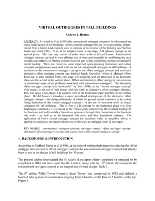
  • 1. VIRTUAL OUTRIGGERS IN TALL BUILDINGS Andrew J. Horton ABSTRACT: As stated by Nair (1998) the conventional outrigger concept is in widespread use today in the design of tall buildings. In this concept, outrigger trusses (or, occasionally, girders) extend from a lateral load-resisting core to columns at the exterior of the building (see Stafford Smith and Coull 1991). It is, in its simplest form, a one-stage, 2-D (planar) concept in the vertical plane. The core may consist of either shear walls or braced frames. Conventional outrigger systems can lead to very efficient use of structural materials by mobilizing the axial strength and stiffness of exterior columns to resist part of the overturning moment produced by lateral loading. There are, however, some important space-planning limitations and certain structural complications associated with the use of conventional outriggers in tall buildings. A variation on the conventional outrigger concept is the offset outrigger concept and associated alternative offset outrigger concept (see Stafford Smith, Cruvellier, Nollet & Mahyari 1996). These are, in their simplest forms, two-stage, 2-D concepts, with the first stage in the horizontal plane and the second in the vertical plane. Offset and alternative offset outriggers can overcome or circumvent many of the problems associated with conventional outriggers. The alternative offset outrigger concept was “re-branded” by Nair (1998) as the “virtual outrigger concept” with respect to the use of belt trusses and belt walls as alternative offset outrigger elements. This was again a two-stage, 2-D concept, first in the horizontal plane and then in the vertical plane. He did however introduce a more specialized development of the alternative offset outrigger concept – the design philosophy of which the present author considers to be a more fitting definition of the virtual outrigger concept – in the use of basement walls as virtual outriggers for tall buildings. This is first a 2-D concept in the horizontal plane (via floor diaphragms) and then a 3-D concept in the vertical plane (transferring the resultant loadings to the basement end walls and their foundation systems – through their connection to the basement side walls – as well as to the basement side walls and their foundation systems). The application of Nair’s virtual outrigger concept for basement walls, as described above, is applied to continuous, perimeter belt trusses or belt walls at outrigger levels in this paper. KEY WORDS: conventional outrigger concept; outrigger trusses; offset outrigger concept; alternative offset outrigger concept; belt trusses; belt walls; virtual outrigger concept 1. BACKGROUND & INTRODUCTION According to Stafford Smith et al (1996), at the time of writing their paper introducing the offset outrigger and alternative offset outrigger concept, the conventional outrigger concept had already been in use in the design of tall buildings for 30 years. The present author investigated the 10 tallest skyscrapers either completed or expected to be completed in 2010 and discovered that the 7 tallest, along with the 10th tallest, all incorporate the conventional outrigger concept as an integral part of their design, Table 1. The 8th tallest, Willis Tower (formerly Sears Tower) was completed in 1973 and utilized a bundled tube system of construction stepping from 9 bundles at the base to 2 bundles at the top, Figure 1.
  • 2. The 9th tallest, Guangzhou West Tower (still under construction) is utilizing a twin tube system of construction with the outer tube (perimeter) being comprised of a diagonal grid (diagrid) of 1600 mm diameter concrete filled tubes with ring beams linked back to the inner tube (core) with tie beams, Figure 2. Table 1: Usage of Conventional Outrigger Concept in Ten Tallest Skyscrapers # Building City Country Height (m) Floors Completed # of Outrigger Levels 1 Burj Khalifa Dubai UAE 828 160 2010 5 2 Taipei 101 Taipei Taiwan (ROC) 509 101 2004 11 3 Shanghai World Financial Centre Shanghai China (PRC) 492 101 2008 8 4 International Commerce Centre Kowloon Hong Kong 483 118 2010 (Expected) 4 5 Petronas Tower 1 Kuala Lumpur Malaysia 452 88 1998 1 6 Petronas Tower 2 Kuala Lumpur Malaysia 452 88 1998 1 7 Nanjing Greenland Financial Centre Nanjing China (PRC) 450 89 2010 (Expected) 3 8 Willis Tower (formerly Sears Tower) Chicago USA 442 108 1973 0 9 Guangzhou West Tower Guangzhou China (PRC) 440 103 2010 (Expected) 0 10 Trump International Hotel and Tower Chicago USA 423 96 2010 3 Figure 1: Willis Tower, Chicago, USA Figure 2: Guangzhou West Tower, Guangzhou, China
  • 3. The present author also conducted an investigation to ascertain the usage of the offset outrigger, alternative offset outrigger and virtual outrigger concepts in approved or completed tall buildings to date, Table 2. Table 2: Usage of Offset, Alternative Offset or Virtual Outrigger Concept in Approved or Completed Tall Buildings # Building City Country Height (m) Floors Approved / Completed # of Outrigger Levels 1 Dubai Tower Doha Doha Qatar 438 90 Approved / Partially Completed / On Hold 3 (1 Conventional; 2 Mixed Conventional / Alternative Offset) 2 Plaza Rakyat Office Tower Kuala Lumpur Malaysia 382 79 Approved / Partially Completed / On Hold 3 (1 Conventional; 2 Virtual) 3 Aston Apartments Residential Tower Sydney Australia 90 30 1998 2 (1 Alternative Offset; 1 Mixed Offset/Alternative Offset) A relative dearth of information is available in the literature regarding the offset, alternative offset and virtual outrigger concepts compared to a relative wealth of information regarding the conventional outrigger concept. The following discussion, after laying the ground work for an understanding of the conventional, offset and alternative offset outrigger concepts, seeks to elaborate further on the use of belt trusses and belt walls, as virtual outriggers in tall buildings. 2. DISCUSSION 2.1 Conventional Outrigger Concept 2.1.1 Explanation Stafford Smith et al (1996) stated that up until that point in time, the outrigger concept, speaking of the conventional outrigger system, had been governed mainly by a planar conceptualization of the interactions between the core walls, the outrigger arms and the exterior columns. Summarizing the functioning of this system, in its simplest form, they stated, that when lateral loading acts along the plane of the outrigger bent, the bending of the core rotates the stiff outrigger arms that cantilever from it, inducing tension in the upwind column and compression in the downwind column. These column forces, acting at the extremities of the outrigger arms, form a couple that restrains the bending and deflection of the core, Figure 3 (taken from Stafford Smith and Coull 1991). Stafford Smith and Coull (1991) stated that in addition to those columns located at the ends of the outriggers, it is usual to also mobilize other peripheral columns to assist in restraining the outriggers. This is achieved by including a deep spandrel girder, or “belt” truss, around the structure at the levels of the outriggers, hence the name, “belt-braced structure”, Figure 4. The present author also makes use of this technique in § 2.3.1, § 2.3.3 and Appendix A of this paper.
  • 4. Figure 3 (a): Outrigger Structure Displaced under Lateral Loading, (b): Resultant Deflections and (c): Resultant Core Moments. Figure 4: Conventional Outrigger Structure with Belt Girders The large, often two-storey, depths of the outrigger and perimeter trusses make it desirable to locate them within the plant levels of the building.
  • 5. Stafford Smith and Coull (1991) further stated that the degree to which the perimeter columns of an outrigger structure behave compositely with the core depends on the number of levels of outriggers and their stiffness. Multilevel outrigger structures show a considerable increase in their effective moment of resistance over single level outrigger structures. Each additional level of outriggers increases the lateral stiffness, but by a smaller amount than the previous additional level with four or five levels appearing to be the economic limit for a tall building. They found that in any outrigger system it is, perhaps unexpectedly, structurally inefficient to locate an outrigger level at the top of the building and that this should only be undertaken when dictated by other constraints, e.g. a plant floor needing to be located at the top of the building. By making the necessary simplifying assumptions, i.e. the structure is linearly elastic, only axial forces are induced in the columns, the outriggers are rigidly attached to the core, the core is rigidly attached to the foundation, the sectional properties of the core, columns and outriggers are uniform throughout their height and expressing the applied lateral load as a uniformly distributed horizontal load over the full height of the building, Stafford Smith and Coull (1991) used established structural theory, i.e. the moment area method, the moment equation for a vertical cantilever, the deflection equation for a vertical cantilever and various axial and flexural stiffness representations, to develop charts expressing the optimum location of outriggers, for an n- outrigger system (where 1 < n < 4), to minimise top of structure lateral deflections. Generally, by making a further (hypothetical) simplifying assumption, i.e. that the outriggers are flexurally rigid, they found, for the optimum performance of an n-outrigger structure, that the outriggers should be placed at the 1/(n+1), 2/(n+1), up to the n/(n+1) height locations, i.e. for a one-outrigger structure at approximately half-height, for a two-outrigger structure at approximately one-third and two-thirds heights, for a three-outrigger structure at approximately one-quarter, one-half and three-quarter heights, and so on. The present author comments that these findings also hold true for the subsequently discussed offset, alternative offset and virtual outrigger systems under similar simplifying assumptions. It should be noted that the optimum outrigger arrangement for the maximum reduction in drift was not found to simultaneously cause the maximum reduction in the core base moment. For this, the outriggers would have to be lowered toward the base. It was suggested in cases where drift control is not critical, that the design emphasis could change to controlling the core moments by lowering the heights of the outrigger levels from the base until the drift limitations are just satisfied but noted, due to other constraints, that this might only be achievable in reality. Wu and Li (2003) followed up on the above optimum outrigger arrangement work by Stafford Smith and Coull (1991) for the case where the applied lateral load is modelled as both a triangular and uniformly distributed horizontal load over the full height of the building. They found when an outrigger-braced structure is subjected to horizontal triangular loads, the optimum locations of outriggers are 4 – 5% higher than those of the structure subjected to horizontal uniform load. In lieu of any further investigation their findings could be used to give a conservative upper bound for optimum outrigger positions under horizontal trapezoidal loading.
  • 6. While the conventional outrigger system is very effective in increasing the structures flexural stiffness, it does not increase its resistance to shear, which has to be carried mainly by the core (Stafford Smith and Coull 1991). The present author comments that this principle also holds true for the subsequently discussed offset, alternative offset and virtual outrigger systems. 2.1.2 Examples The 492 m height, 101 floors, Shanghai World Financial Centre, designed by Leslie E. Robertson Associates, completed in 2008 in China, has 8 conventional outrigger levels, Figure 5. Figures 5 (a) and (b): Model showing the Building’s Mega-Structure System of Mega-Columns, Diagonals and Belt Trusses along with Concrete Core Walls and Outrigger Trusses Figure 5 (c): Tie Columns, Diagonals, Belt Trusses and Outrigger Trusses Connected to the Concrete Shear Walls of the Service Core The 450 m height, 89 floors, Nanjing Greenland Financial Centre, designed by Skidmore, Owings and Merrill (SOM), presently under construction in China, has 3 conventional outrigger levels, Figure 6. Figure 6 (a): Outrigger and Belt Truss Configuration, (b): Typical Outrigger Truss – Continuous through Core and (c): Photograph of Outrigger Truss Construction
  • 7. The 360 m height, 93 floors, Federation Tower, Tower A, designed by Thornton Tomasetti, presently under construction in Moscow, Russia, has 2 conventional outrigger levels, Figure 7. Figure 7 (a): Model of 61st Floor Outrigger Level Figure 7 (b): 33rd Floor Outrigger Trusses linking the Belt Trusses (Left) to the Central Core 2.2 Offset and Alternative Offset Outrigger Concepts 2.2.1 Explanation Stafford Smith et al (1996) proposed that the outriggers may be located elsewhere than in the planes of the core walls, while retaining all the advantages and mitigating some of the disadvantages of the conventional outrigger system. They proposed to move, or offset, the outrigger arms horizontally within the floor plan, away from the central elevator core, Figure 8. Detailed structural analysis conducted on buildings incorporating such laterally shifted outriggers indicated that, compared to the conventional arrangement – Figure 8 (b) – the offset outrigger concept – Figure 8 (c) – as defined above and compared with the conventional outrigger system, was virtually 100% effective in reducing the building deflections and the core bending stresses resulting from centred wind or earthquake loading (Stafford Smith et al 1996). Moreover, for typical floor slab plan dimensions and thicknesses, they discovered that there was little reduction in the effectiveness of the offset outrigger as it is shifted further from the central core – becoming the alternative offset concept, as represented in Figure 8 (d). For the offset outrigger system to work, it is essential that the floor slabs be effectively rigid and strong enough in their planes to transfer the horizontal plane shears between the outrigger arm and the core. For typical residential and office floor layouts, the slabs will be thick enough and the building dimensions will be sufficient to ensure that this condition is easily met (Stafford Smith et al 1996).
  • 8. They further noted that it is also necessary for the outrigger arm to be as rigid as possible in flexure across the width of the building (similar to the stiffness requirement for the conventional outrigger). In both cases – offset and alternative offset – there are many ways to achieve adequate stiffness, be it with diagonal bracing (belt trusses) or reinforced concrete in-filled panels (belt walls). Just as in the case of the conventional outrigger system, the outrigger arm in the offset system may also be spread vertically over several stories in order to reduce the obstruction at any individual floor level. Stafford Smith et al (1996) also alluded to studies indicating potentially significant structural benefits arising from the offset outrigger system in terms of the building’s torsional response to off centre loading. The maximum benefit was reported to be obtained by offsetting the outriggers on plan as far as possible from the centre of rotation of the building, i.e. to the perimeter. With the addition of a full-depth of outrigger level, continuous, perimeter belt truss or belt walls to the two remaining horizontal sides of Figure 8 (d) the alternative offset outrigger concept would match the definition provided by the present author of the virtual outrigger concept stated in § 2.3.1 of this paper. Figure 8 (a): Typical Floor Plan Figure 8 (b): Conventional Outrigger Plan Figure 8 (c): Offset Outrigger Plan Figure 8 (d): Alternative Offset Outrigger Plan In summary the case was made by Stafford Smith et al (1996) that, in terms of structural efficiency, nothing is lost by laterally offsetting outriggers from the plane of the central core walls and that a considerable advantage of this new configuration is greater flexibility of the building floor plan to met functional and aesthetic design requirements.
  • 9. The relevant load transfer mechanism for the alternative offset outrigger concept shown below in Figure 9 is fully explained in Stafford Smith et al (1996). Figure 9 (a): Axonometric View Figure 9 (b): Relative Displacements of Slabs considering only the Core Wall Figure 9 (c): Outrigger subject to Couple from Slabs Figure 9 (d): Restraining Couple from Perimeter Columns Figure 9 (e): Restraining Couple from Perimeter Columns back through Slabs to Core 2.2.2 Example The 90m height, 30 floors, Aston Apartments Residential Tower, designed by Connell Wagner, completed in 1998 in Sydney, Australia, has 1 alternative offset outrigger level (roof) and 1 mixed offset and alternative offset outrigger level (mid-height), Figure 10 (taken from Dean, Martin, Emery and Chancellor 2001).
  • 10. The reinforced concrete frame structure with central lift core – quoted as being the first “offset outrigger” building in Australasia – is only 13m wide in the North-South direction resulting in a slender height-to-base ratio of 7:1. The “offset outriggers” – comprising of two storey high shear walls 200 mm thick – significantly reduce building deflections and core bending moments. Core wall thicknesses were able to be limited to 200 mm even in the lower levels (Dean et al 2001). Figure 10: Frame Perspective – Aston Apartments Residential Tower 2.3 Virtual Outrigger Concept 2.3.1 Explanation Following on from Stafford Smith et al (1996), Nair (1998) coined the phrase “virtual” outriggers to refer to a subset of offset outriggers, previously termed alternative offset outriggers, which were to be located only at the perimeter of the building and which were not to be directly attached to the core, stating that belt trusses and belt walls were well suited for use as “virtual” outriggers. A close investigation, however, of Nair (1998) reveals that, with respect to the belt trusses (or belt walls) at outrigger level, Nair was not considering that the belt trusses (or belt walls) in the plane perpendicular to the action of lateral load could also be mobilised to distribute the resultant tensile and compressive “stresses”, refer to Figure 12 below, to all of the perimeter columns, refer also to § 2.3.3 and Appendix A.
  • 11. Nair (1998) also used the phrase to refer to a “more specialized development” of the alternative offset outrigger concept – the design philosophy of which the present author considers to be a more fitting definition of the virtual outrigger concept – in the use of basement walls as “virtual” outriggers for tall buildings. This is first a 2-D concept in the horizontal plane (via floor diaphragms) and then a 3-D concept in the vertical plane (transferring the resultant loadings to the basement end walls and their foundation systems – through their connection to the basement side walls – as well as to the basement side walls and their foundation systems), Figure 11 (taken from Nair 1998). Figure 11. Force Transfer using Basement as Virtual Outrigger System For the purpose of this paper, the present author would like to define the virtual outrigger concept as being where belt trusses or belt walls are provided, full depth, continuously, around the perimeter of an outrigger level – in a square or appropriately proportioned rectangular on plan building – and act, together with the top and bottom structural diaphragm of the outrigger level, to transfer substantially the same magnitude of overturning moment from the core to the perimeter columns – engaging axially all of the perimeter columns – as could realistically be achieved via the use of conventional outriggers. Leonard (2007), speaking with reference to framed tube structures but equally applicable to virtual outrigger structures, stated that shear lag effects can be reduced by employing additional structural systems which increase the stiffness of the overall structural system, Figure 12. He further stated that belt trusses effectively increase the shear stiffness of framed tube structures by integrating all the columns in the same face of the building. He additionally stated that belt trusses can also be added at multiple levels of a framed tube system. He finally stated that one of the ideas similar to the belt truss system was the offset outrigger system proposed by Stafford Smith et al (1996) and Nair (1998).
  • 12. Figure 12: Axial Stress Distribution in Box Structure: (a) Without Shear Lag and (b) With Shear Lag If the stiffness of the belt truss or belt wall system in the virtual outrigger concept defined by the present author can cause the axial loads on the “flange” perimeter columns to approach what is depicted in Figure 12 (a) above then the capability of the system would better any conventional outrigger system which did not have a belt truss or belt wall system sufficient to spread axial loads along the “flange” and rival any conventional outrigger system which did. 2.3.2 Example The 382 m height, 79 floors, Plaza Rakyat Office Tower, designed by SOM, construction commenced circa 1996, stalled due to the 1997 Asian Financial Crisis and presently still on hold in Kuala Lumpur, Malaysia, has 1 conventional outrigger level at roof height and two virtual outrigger levels, Figure 13. Further information is available in Baker, Brown and Sinn (1997). Figure 13: Model of Plaza Rakyat Office Tower (taken from SOM)
  • 13. 2.3.3 Finite Element Model (FEM) Investigation A FEM was prepared for purpose of comparison with the results stated by Nair (1998) for his example “75-story steel framed office tower”. The present author noted that the chamfered corners in plan and light bracing in elevation adopted by Nair around these chamfered corners effectively inhibited the full potential of the virtual outrigger concept, as defined by the present author, from being realised. The FEM prepared removed the chamfers, placed “super-columns” at the corners and continued the belt truss bracing around the entire outrigger level. Apart from this modification the FEM compared “apples with apples” based on Nair’s provided information. With the above modification the present author discovered that the onerous and inhibitive measures proposed by Nair as being necessary to “match” the performance of a conventional outrigger system were no longer required. In summary, a 2-fold increase in outrigger diaphragm thicknesses (not a 10-fold increase in stiffness as proposed by Nair) coupled with a 16% increase in belt truss area (not 10-fold increase in stiffness as proposed by Nair) sufficed to enable the virtual outrigger system to perform within 4% of the lateral deflection capacity achieved by the conventional outrigger system. Concrete belt walls were also substituted for the steel belt trusses at outrigger levels to good effect in the FEM and an alternative reinforced concrete structure was also modelled with virtual versus conventional outrigger performance compared. The results of the FEM investigation are included in Appendix A. 3. SUMMARY & CONCLUSION The virtual outrigger system, as defined by the present author, is found to be capable of providing comparable performance to the conventional outrigger system. The virtual outrigger system thus employed would eliminate the need to attach outrigger members to the core for square or appropriately proportioned rectangular on plan buildings. Additionally, when utilizing the virtual outrigger system, outrigger levels could be placed at optimum levels up the height of the building, as the virtual outrigger members, i.e. belt trusses or belt walls, are positioned on the perimeter of the building. Furthermore, the adoption of the virtual outrigger system, with its full depth, continuous, perimeter belt trusses or belt walls at outrigger levels would result in a reduction in potential “shear lag” type effects in the perimeter columns of the building. Finally, the virtual outrigger system would also dually offer the building enhanced torsional resistance and reduced susceptibility to the differential shortening effects encountered by the conventional outrigger system.
  • 14. REFERENCES Baker, W. F., Brown, C. D. and Sinn, R. C. (1997). Structural Analysis and Design of the World’s Tallest Reinforced Concrete Building. E & FN Spon. Multi-Purpose High-Rise Towers and Tall Buildings, 333–346. Dean, B., Martin, O., Emery, D. and Chancellor, P. (2001). Tall Building Design Innovations in Australia. Tall Buildings and Urban Habitat, Cities in the Third Millennium, 6th World Congress of the Council On Tall Buildings and Urban Habitat, Melbourne, 26 February to 2 March 2001. Planning and Architecture, 393–394. Leonard, J. (2007) Investigation of Shear Lag Effect in High-Rise Buildings with Diagrid Systems. Degree of Master of Engineering in Civil and Environmental Engineering. Department of Civil and Environmental Engineering, Massachusetts Institute of Technology. Nair, R. Shankar (1998) Belt Trusses and Basements as “Virtual” Outriggers for Tall Buildings. American Institute of Steel Construction. Engineering Journal, Fourth Quarter, 140–146. Stafford Smith, B. and Coull, A. (1991) Tall Building Structures: Analysis and Design. John Wiley and Sons, Inc. Chapter 14, Outrigger-Braced Structures, 355–371. Stafford Smith, B., Cruvellier, M., Nollet, M-J. and Mahyari, A. T. (1996) Offset Outrigger Concept for Tall Building Structures. Council on Tall Buildings and Urban Habitat. Tall Building Structures – A World View, 73–80. Wo J. R. and Li, Q. S. (2003) Structural Performance of Multi-Outrigger-Braced Tall Buildings. Published online in Wiley InterScience (www.interscience.wiley.com). DOI:10.1002/tal.219. The Structural Design of Tall and Special Buildings 12, 155–176. ABOUT THE AUTHOR Andrew J. Horton, BE(Hons), MIPENZ(Structural), CPEng, IntPE(NZ), Structural Design Manager, Hyder Consulting Middle East Ltd, Global Design Centre – Manila, Philippines. Email: andrew.horton@hyderconsulting.com. ACKNOWLEDGEMENTS Francis O. Macatingrao, B.S. C.E., Graduate Structural Engineer and Carlos Alfonso V. Fabie, B.S. C.E., Assistant Structural Engineer, Hyder Consulting Middle East Ltd, Global Design Centre – Manila, Philippines. Email: francis.macatingrao@hyderconsulting.com and carlos.fabie@hyderconsulting.com. Milan Petrovic, dipl.inž., Senior Structural Engineer, Hyder Consulting Middle East Ltd, Dubai, UAE. Email: milan.petrovic@hyderconsulting.com. Marie-José Nollet, ing., Ph.D., Département de génie de la construction, École de technologie supérieure, 1100, rue Notre-Dame ouest, Montréal, Qc, H3C 1K3, Canada. Email: marie-jose.nollet@etsmtl.ca.
  • 15. APPENDIX A STEEL FEM SUMMARY Ratio of Lateral Displacement at Top for Outrigger Type i Versus Lateral Displacement at Top without Outriggers (SLS Wind) Type of Outrigger From Present FEM Analysis From Literature (%) (%) Conventional Outrigger 22.2 23.3 Belt Truss as Virtual Outrigger 25.7 34.2 Ratio of Σ Total Outrigger Moment Type i at Base Versus Σ Total Moment at Base Type of Outrigger From Present FEM Analysis (%) Conventional Outrigger 56.9 Belt Truss as Virtual Outrigger 52.0 As shown in the following table, in the Steel FEM Analysis an equivalent 100mm thick continuous perimeter concrete belt wall may be used to replace the above continuous perimeter steel belt truss system – holding everything else constant – to achieve the same lateral performance. Moreover, the performance of the structure may be further enhanced by thickening these concrete belt walls. Using Concrete Belt Walls as Virtual Outriggers Thickness Lateral Displacement at Top due to SLS Wind (m) Reduction in Lateral Displacement at Top compared with Steel Belt Truss (%) 100mm 0.620 0.9 200mm 0.565 8.6 300mm 0.543 13.0 CONCRETE FEM SUMMARY Type of Outrigger Ratio of Lateral Displacement at Top for Outrigger Type i Versus Lateral Displacement at Top without Outriggers (SLS Wind) (%) Conventional Outrigger 29.2 Belt Wall as Virtual Outrigger 27.2
  • 16. Type of Outrigger Ratio of Σ Total Outrigger Moment Type i at Base Versus Σ Total Moment at Base (%) Conventional Outrigger 54.0 Belt Truss as Virtual Outrigger 52.0 MODELLING ASSUMPTIONS 1. The structural diaphragms were assumed to have no out of plane stiffness. 2. SLS Wind Combinations and Wind Loads were as per ASCE 7-05 code provisions. ADDITIONAL FEM ANALYSIS Subsequent modifications to the steel belt truss system were performed in the Steel FEM in order to achieve the same lateral performance as the conventional outrigger system. This is summarized in the tables below. Before any modifications were made the following table shows the results: Type of Outrigger Lateral Displacement at Top due to SLS Wind (m) Without Outrigger 2.386 Conventional Outrigger 0.529 Virtual Outrigger 0.614 The ratio of virtual outrigger to conventional outrigger displacement is approx 16.1%. The following modifications were then made to the steel beam truss virtual outrigger system: Modifications to Belt Truss System (Normal-Weight Concrete) SLS Deflection (m) Comparison to Performance of Conventional Outrigger (% Difference) 1.6 x Increase in Outrigger Diaphragm Thicknesses 0.599 13.2 2.0 x Increase in Outrigger Diaphragm Thicknesses 0.592 11.9 Increase Bracing Size in Belt Trusses from W14x730 to W36x848 (Increase in Area by 15.8%) without Increasing Outrigger Diaphragm Thicknesses 0.593 12.1 Combined 2.0 x Increase in Outrigger Diaphragm Thicknesses and Increase in Bracing Size from W14x730 to W36x848 0.552 4.3 The above table shows that an increase in outrigger diaphragm thicknesses alone has no significant effect on the lateral performance of the structure. An increase in bracing size alone, likewise exhibits similar behaviour. A combination of increased outrigger diaphragm thicknesses and bracing size are required in order to achieve a comparable lateral performance with the conventional outrigger system. However, this is not considered to be a cause for concern since the required structural system can be designed economically to meet the necessary demand.