SlideShare uma empresa Scribd logo
1 de 2
Baixar para ler offline
TECHNICAL DIRECTORSTECHNICAL DIRECTORS28 29
Coping with flexible and umbilical laying:
state of art capabilities
Saipem S.p.A.
Saipem S.p.A.
Saipem S.p.A.
SPE Italian Section Proj-
ects, Facilities and Con-
struction Technical Director
Valerio Bregonzio
Roberto Raglione
Andrea Intieri
INTRODUCTION
The use of umbilicals and flexible pipes
in the Offshore Industry is today a wide-
spread option for the exploitation of oil
and gas reservoirs. The increased con-
fidence gained by the Operators with
these products, coupled with a clear
need to follow the trend for field devel-
opments in deep and ultra deep waters,
led the URF (Umbilicals, Risers, Flow-
lines) contractors develop high-tech
solutions in order to carry out safe and
reliable operations with these products.
This article provides an overview of a
typical flexible and umbilical laying sys-
tem also showing the main characteris-
tics of a state of the art equipment such
as the one onboard Saipem’s latest ves-
sel, Normand Maximus.
An overview of Flexible Laying Systems
A Flexible Laying System comprises a
storage system, a handling system and
a laying system either horizontal (HLS)
or vertical (VLS).
The function of the storage system is to
duly store the product(s) to be laid in the
most appropriate manner depending on
a number of factors such as product(s)
type, size, weight, stiffness, minimum
bending radius, storage specifications
etc; it is also in charge of the delivery of
the product to the downstream laying
system through the handling system.
A broad distinction can be made for
these types of systems as follows: Reel
Hub Drives, Carousels or Baskets. Oth-
er minor systems are less important. In
the following sections, a more detailed
description of the first and second items
will be provided.
The handling system has the function
to guide and contain the product prior to
its ingress in the laying system. It may
consist of rollerways with/without fric-
tion pads with ramps and bends upon
necessity. The guiding system serves to
connect the storage system to the lay-
ing system making sure the product is
transferred safely and efficiently. The
need and design of a handling system
depends on the deck layout, available
spaces and ancillary activities including
termination handling, crane, wire rope
access etc. To give an example, there
are cases where the product is routed
through the installation vessel deck and
an articulated handling system is envis-
aged, whereas where removable laying
systems are considered, e.g. removable
VLS tower and/or carousel, a handling
system may not be necessary and the
storage system may feed the laying sys-
tem directly, optionally requiring minor
modifications to the carousel spooling
tower at the tensioner outlet. (Fig. 1)
As said, the laying system can be broad-
ly divided into two categories: horizontal
and vertical. A horizontal flexible laying
system consists of one or two tensioners
arranged in a row horizontally or inclined
(roughly up to 45°) and an over-boarding
structure, mostly in the form of a chute
(but wheels and freeboards may be pos-
sible). A chute serves as a mean to launch
the product by guiding it from the outlet
of the tensioners all the way to a vertical
or near-vertical inclination. It is normally
designed as a fixed sliding surface with
containmentedges.Itistypicaltofindsys-
tems of 20Te to 75Te capacity, of compact
size also featuring removability, allowing
higher adaptability to variable deck con-
figurations.
In order to be able to exert higher laying
tensions while not loading the product ex-
cessivelyinaradialdirection(duetobend-
ing forces), a vertical laying system (VLS)
is more effective.
The idea is to vertically arrange one or two
tensioner(s) in a tower structure equipped
with a product inlet chute at the top (al-
ternative designs exist). The tower may
be fixed or inclinable normally up to 10°
with regards to the vertical position, offer-
ing an advantage with stiff products and/
or shallower waters. The tower may be of
permanent or removable type, but in the
latter case with a lower tensioning capac-
ity (around 100Te maximum): a suitable
example is Saipem’s 90Te removable VLS
tower, which can be efficiently installed on
board of an Offshore Construction Vessel
(OCV). Generally speaking, a VLS tower
may be installed either on a moon-pool or
on a side of the vessel or astern. From this
standpoint, industrially, there is a wide
variability of combinations of tower con-
figurations, tensioning capacities, num-
ber of tensioners and positions. Finally
yet importantly, it shall be remembered
that tensioners borne to handle flexible
products are characterized normally by
a 4-track design that allows maximizing
contact length vs contact pressure. Being
armed with special friction pads, contact
lengths range between 1,5m-2m to 4,5m-
5m depending on capacity and design.
Termination handling and opening/closing
most often call for openable tensioners,
where one track is mounted on a revolving
structure or more simply for retractable
tensioners.
There is also a number of ancillary sys-
tems, necessary for properly executing
laying operations that will not be treated
in this article: for example, A&R winches,
under-tower openable tables, emergency
clamps, tower cranes, routing arches.
Focus on storage systems:
Reel Hub Drives (RHD) and Carousels
Reeldrivesystems are mobile equipment
used for spooling and unspooling of rigid
and flexible pipe, umbilicals, risers and
other products for offshore applications,
stored on multiple vertical reels.
The RHD has a versatility to manage vari-
ous products, stored in the reels.
The reel drive system consists of two
drive/lifting towers that lift the reel from
its cradle for spooling. The towers can
move along two skid beams, skidding
from one spooling position to the next. At
this location, it will pick up a reel for un-
spooling.
The system can be built with various reel
interfaces suited for flexible pipes stan-
dards. The system is completed by:
• level winders to guide the products
• control systems to satisfy safety re-
quirements during product handling in
operation activities. Control system per-
mit to operate in Speed mode, Torque
mode, Tension Mode
• measure unit to calculate the products
length.
The main design considerations are: type
of vessel / operating conditions, deck /
system arrangement, available deck area,
vessel deck loading capacity, gross weight
of reel and product, reel diameter, reel
width, interface details, maximum torque,
angle or multiple reel handling, power
drive: hydraulic / electric.
Saipem is equipped with various of these
system, able to manage all offshore prod-
uctsandabletoworkworldwideforglobal
energy projects.
Basically, it consists of a motorized re-
volving drum of vertical axis: the prod-
uct is wound and packed under tension
around the core assisted by a spooling
tower, which acts also as a level winder,
between the roof and the floor.
It shall not be considered equivalent to
the carousel basket or turntable mod-
els, having them different features as re-
minded above. Baskets (Fig. 4) work in a
similar manner to Carousels except that
they feature a storing system consisting
of external containment walls/beams at
the periphery (and in some instances with
intermediate separate sectors along the
radius) and an open-top design.
The product is deployed into the basket
(horizontal layering) from a loading arm
allowing it to form a natural catenary
under its self-weight and making it easy
to manipulate within the basket. On the
opposite, on a carousel, the product is
spooled on under tension normally due to
the high product stiffness, using a spool-
ing unit that traverses vertically (vertical
layering) between the carousel flanges.
In a carousel the roof can be designed
closed with suitable openings (normally
45°), ‘wireframed’ or in some cases may
be absent. It has the function to support
the product ends (while allowing its ac-
cess underneath) prior to starting the
storage operation and to ease and secureFig.1: Reel hub drive
assembly
Fig.2: Reel with product
Fig.3: 20m OD carousel for flexible products
Fig.4: Basket
TECHNICAL DIRECTORSTECHNICAL DIRECTORS
Andrea Intieri
Andrea has more than ten years of experience in the
energy industry and currently works in Saipem’s Mar-
keting department. His interests include the genera-
tion and development of new technical-commercial op-
portunities in the offshore deep and ultra-deep water
oil & gas developments and in the subsea processing
technologies. Andrea holds a Master’s Degree with
honours in Industrial Engineering from the Technical
University of Milan, Italy, and a M.B.A. at the MIP School
of Management, Italy. He is the SPE Italian Section Project, Facilities, Construc-
tion Technical Director.
Valerio Bregonzio
Presently part of the Offshore R&D projects portfolio
management unit, he has 14 years of experience in
the offshore O&G industry. He committed many years
to Research and Development, starting out as an R&D
engineer in charge of the improvement of pipelay
equipment and at a later stage became R&D project
manager of technology innovation projects, growing
also intellectual property management competences.
He was also field engineer in the Green Stream pipelay
project, involved in the offshore field activities. In the last years, before joining the
Technology and innovation unit, he strengthened his technical background in the
Asset department for about two years, in charge of the preparation and upgrade
of flexible products lay systems.
the packing operation. Bearing capacity
of the roof structure plays an important
role and can reach tens of tons. The floor
supports the product weight, while trans-
ferring it to the drum support structure
(the physical interface with the vessel) of
which a variety of designs exist. There is
vast range of systems and designs avail-
able on the market today that offer differ-
ent features, but normally adjustable core
diameterandroofheightarecommonfea-
tures.
Smallest carousels range slightly below
1,000Te payload capacity with outer diam-
eters roughly around 10m while largest
carousels can reach 5,000Te to 10,000Te
and over 30m of outer diameter. Height
rangesvarywidelyaswell,but4m-6mcan
be considered a good reference. Last but
not least, carousels can be permanently
installed on a vessel (on deck or inside the
ship’s body) or can be of removable type,
i.e. they are not permanently installed
on- board of a vessel for obvious reasons.
Oneofthetypesofthelattermodelisaso-
called “liftable carousel” (reported in Fig.
6), an advantageous model which Saipem
has benefitted from since a few years. The
underlying concept is to take advantage of
the possibility to do a single lift of the en-
tire(loaded)carousel(Fig. 6)thusavoiding
otherwise costly or lengthy trans-pooling
operations. The system comes with the
additional flexibility to allow alternatively
the single lift of the (loaded) drum.
Focus on removable VLS
Saipem 90Te Vertical Laying System is a
removable piece of equipment where the
main components are a Steel framework
and a 90Te capacity tensioner.
The steel framework, named the Lay
Tower, has the function to accommodate
a 90Te Tensioner (complete with top arch
and work platforms) to perform umbilical,
flexible pipe and cable laying in deepwa-
ter.
The whole structure may be divided into
three main items:
• a fixed 3D base frame bolted to the deck
grillage,
• a vertical frame hinged at the column
base to the base and equipped two tilting
cylinders. The frame and the attached
tensioner may be tilted from vertical posi-
tion in the range from 0° to 10° (inboard).
A hydraulic centralizer and an emergency
clamp (for emergency cases) are also fea-
tured,
• a box girder formed in a top circular arch
whose function is to accommodate rollers
upon which the product will run.
A 4-track pipe tensioner is designed to
perform the laying of flexible pipelines in
the sea applying the required tension load
at the required speed.
State of art capabilities:
Normand Maximus’ vertical
laying system
Offshore contractors offer a wide range
of VLS capacities: beyond removable sys-
tems, 100Te-120Te permanent systems
exist as well as often in the 275Te-350Te
range. Top-range systems belong to the
permanent moon-pool tower type, typi-
cally featuring a laying capacity of 550Te
to 650Te.
A good example of a state-of-art vessel
is Saipem’s Normand Maximus (Fig. 8),
equipped with a permanent VLS of 550Te
capacity designed for the installation of
flexible and rigid reeled products ranging
from 50 mm to 700 mm outside diameter
(up to 12” for rigid pipes OD).
NormandMaximus,deliveredthisyearaf-
ter final outfittings in Norway, is the result
of an innovative design philosophy aimed
at combining SURF installation with field
development activities in ultra-deep wa-
ters. This DP3 vessel is about 178 meters
long, with a beam of 33 meters, a deck
area of more than 2.500 m2 and is able to
accommodate 180 people.
Normand Maximus provides unique op-
erational benefits in terms of versatility,
as it is reconfigurable for multiple and
simultaneous project tasks. It is designed
to perform in the harshest environmental
conditions thanks to its DNV Ice class C.
It is also equipped with latest generation
ROV, the Sonsub INNOVATOR 2.0.
The VLS is positioned aft of the vessel
moonpool and accommodates two 275Te
tensioners, also being able to be inclined
by +/-10˚. An under deck basket is locat-
ed aft of the VLS for the storage of up to
3,800Te of flexible products. Moreover,
additional removable Basket or RHD can
be accommodate on Vessel deck to supply
the product to the Tower.
Conclusions
The article provided an overview of a typ-
ical flexible and umbilical laying system,
describing its main components and char-
acteristics and also showing the main fea-
tures of a state of the art equipment such
as the one onboard Saipem’s latest ves-
sel, Normand Maximus.
Fig.5: Spooling tower (in foreground) and 20m OD
carousel
Fig.6: Unique lift of loaded carousel and basement
Fig.7: 90Te VLS on board of an OCV
Fig.8: Saipem’s Normand Maximus at the naming cerimony
Roberto Raglione
Roberto has more than fifteen years of experience in
the energy industry and currently works in Saipem’s
Asset Department. His interests include the develop-
ment of laying systems and new technical opportu-
nities in the offshore oil & gas field. Roberto holds a
Master’s Degree in Civil-structural Engineering from
the Pisa University, Italy, and Master in Engineering and
Contracting – Project Management at the MIP School of
Management, Italy. He is the SPE Italian Section Project, Facilities, Construction
member.

Mais conteúdo relacionado

Mais procurados

0020 introduction to fpso design
0020 introduction to fpso design0020 introduction to fpso design
0020 introduction to fpso designChieu Nguyen
 
Introduction to offshore structures
Introduction to offshore structuresIntroduction to offshore structures
Introduction to offshore structuresNitish Anand
 
Offshore 187
Offshore 187Offshore 187
Offshore 187leemayza
 
Report on Madras Atomic Power Station Emass Coolant Channel Replacement
Report on Madras Atomic Power Station Emass Coolant Channel ReplacementReport on Madras Atomic Power Station Emass Coolant Channel Replacement
Report on Madras Atomic Power Station Emass Coolant Channel ReplacementSujit Tharakan
 
Ppt report on offshore Platform Designs
Ppt report on offshore Platform DesignsPpt report on offshore Platform Designs
Ppt report on offshore Platform DesignsSUBHAM DEY
 
Offshore fixed platforms
Offshore fixed platformsOffshore fixed platforms
Offshore fixed platformsAmit Purohit
 
Aqua-Barrier Water Inflated Dams Literature
Aqua-Barrier Water Inflated Dams LiteratureAqua-Barrier Water Inflated Dams Literature
Aqua-Barrier Water Inflated Dams LiteratureDarren Miller
 
C9 FPSO Layout and Turret 2004
C9 FPSO Layout and Turret 2004C9 FPSO Layout and Turret 2004
C9 FPSO Layout and Turret 2004David Seow
 
Topsides installation options for semi-submersible floating production systems
Topsides installation options for semi-submersible floating production systemsTopsides installation options for semi-submersible floating production systems
Topsides installation options for semi-submersible floating production systemsNiels Haakman
 
FPSO Redeployment
FPSO RedeploymentFPSO Redeployment
FPSO RedeploymentDan Benson
 
PD193 FPSO & FLNG DESIGN & tECHNOLOGY -LEVEL 2
PD193 FPSO & FLNG DESIGN & tECHNOLOGY -LEVEL 2PD193 FPSO & FLNG DESIGN & tECHNOLOGY -LEVEL 2
PD193 FPSO & FLNG DESIGN & tECHNOLOGY -LEVEL 2Zaharah Kasim
 

Mais procurados (20)

0020 introduction to fpso design
0020 introduction to fpso design0020 introduction to fpso design
0020 introduction to fpso design
 
apl-brochure
apl-brochureapl-brochure
apl-brochure
 
Introduction to offshore structures
Introduction to offshore structuresIntroduction to offshore structures
Introduction to offshore structures
 
Offshore 187
Offshore 187Offshore 187
Offshore 187
 
Final ppt of ts
Final ppt of tsFinal ppt of ts
Final ppt of ts
 
Floting Production Storage and Offloading
Floting Production Storage  and OffloadingFloting Production Storage  and Offloading
Floting Production Storage and Offloading
 
Report
ReportReport
Report
 
Offshore structures
Offshore structuresOffshore structures
Offshore structures
 
Tensar mining brochure
Tensar mining brochureTensar mining brochure
Tensar mining brochure
 
Report on Madras Atomic Power Station Emass Coolant Channel Replacement
Report on Madras Atomic Power Station Emass Coolant Channel ReplacementReport on Madras Atomic Power Station Emass Coolant Channel Replacement
Report on Madras Atomic Power Station Emass Coolant Channel Replacement
 
Ppt report on offshore Platform Designs
Ppt report on offshore Platform DesignsPpt report on offshore Platform Designs
Ppt report on offshore Platform Designs
 
Shipyard layout improvement
Shipyard layout improvementShipyard layout improvement
Shipyard layout improvement
 
Offshore fixed platforms
Offshore fixed platformsOffshore fixed platforms
Offshore fixed platforms
 
Aqua-Barrier Water Inflated Dams Literature
Aqua-Barrier Water Inflated Dams LiteratureAqua-Barrier Water Inflated Dams Literature
Aqua-Barrier Water Inflated Dams Literature
 
Offshore Platforms
Offshore Platforms Offshore Platforms
Offshore Platforms
 
C9 FPSO Layout and Turret 2004
C9 FPSO Layout and Turret 2004C9 FPSO Layout and Turret 2004
C9 FPSO Layout and Turret 2004
 
Semi submersible
Semi submersibleSemi submersible
Semi submersible
 
Topsides installation options for semi-submersible floating production systems
Topsides installation options for semi-submersible floating production systemsTopsides installation options for semi-submersible floating production systems
Topsides installation options for semi-submersible floating production systems
 
FPSO Redeployment
FPSO RedeploymentFPSO Redeployment
FPSO Redeployment
 
PD193 FPSO & FLNG DESIGN & tECHNOLOGY -LEVEL 2
PD193 FPSO & FLNG DESIGN & tECHNOLOGY -LEVEL 2PD193 FPSO & FLNG DESIGN & tECHNOLOGY -LEVEL 2
PD193 FPSO & FLNG DESIGN & tECHNOLOGY -LEVEL 2
 

Semelhante a ottobre 2016 - articolo Saipem bollettino SPE

Seawind Copenhagen Paper 20150310
Seawind Copenhagen Paper 20150310Seawind Copenhagen Paper 20150310
Seawind Copenhagen Paper 20150310Ray Dackerman
 
Precision Processing Equipment Kolkata
Precision Processing Equipment KolkataPrecision Processing Equipment Kolkata
Precision Processing Equipment Kolkataprepec
 
Reverse stacking of containers
Reverse stacking of containersReverse stacking of containers
Reverse stacking of containersAveek Bhaduri
 
AViTEQ Linear Feeder Brochure
AViTEQ Linear Feeder BrochureAViTEQ Linear Feeder Brochure
AViTEQ Linear Feeder BrochurePaul Fletcher
 
4.2 Offshore platform.pptx
4.2 Offshore platform.pptx4.2 Offshore platform.pptx
4.2 Offshore platform.pptxVijayalakshmiR64
 
Stahl SH Wire Rope Hoist br_sz_sh_en_150325_web
Stahl SH Wire Rope Hoist br_sz_sh_en_150325_webStahl SH Wire Rope Hoist br_sz_sh_en_150325_web
Stahl SH Wire Rope Hoist br_sz_sh_en_150325_webMarvin Smith
 
Offshore Vessels Equipment New
Offshore Vessels Equipment NewOffshore Vessels Equipment New
Offshore Vessels Equipment Newluca1963
 
Design, Simulation & Optimization of Gravity Spiral Roller Conveyer with Auto...
Design, Simulation & Optimization of Gravity Spiral Roller Conveyer with Auto...Design, Simulation & Optimization of Gravity Spiral Roller Conveyer with Auto...
Design, Simulation & Optimization of Gravity Spiral Roller Conveyer with Auto...IRJET Journal
 
ORWELL OFFSHORE Brochure 2015 v13
ORWELL OFFSHORE Brochure 2015 v13ORWELL OFFSHORE Brochure 2015 v13
ORWELL OFFSHORE Brochure 2015 v13Stephen Adams
 
Scaffolding
ScaffoldingScaffolding
Scaffoldingstooty s
 
Scaffolding
ScaffoldingScaffolding
Scaffoldingstooty s
 
Scaffolding
ScaffoldingScaffolding
Scaffoldingstooty s
 
Ivt forking out on safe positions
Ivt forking out on safe positionsIvt forking out on safe positions
Ivt forking out on safe positionsUwe Killmann
 
Floor Loading Considerations for High Density Storage
Floor Loading Considerations for High Density StorageFloor Loading Considerations for High Density Storage
Floor Loading Considerations for High Density StorageSignUp.com
 
Ship unloading systems: Mechanical Vs Pneumatic?
Ship unloading systems: Mechanical Vs Pneumatic?Ship unloading systems: Mechanical Vs Pneumatic?
Ship unloading systems: Mechanical Vs Pneumatic?Milling and Grain magazine
 
heavylift and rigging.pdf
heavylift and rigging.pdfheavylift and rigging.pdf
heavylift and rigging.pdfssuser4af30f
 

Semelhante a ottobre 2016 - articolo Saipem bollettino SPE (20)

Seawind Copenhagen Paper 20150310
Seawind Copenhagen Paper 20150310Seawind Copenhagen Paper 20150310
Seawind Copenhagen Paper 20150310
 
Precision Processing Equipment Kolkata
Precision Processing Equipment KolkataPrecision Processing Equipment Kolkata
Precision Processing Equipment Kolkata
 
Reverse stacking of containers
Reverse stacking of containersReverse stacking of containers
Reverse stacking of containers
 
5
55
5
 
AViTEQ Linear Feeder Brochure
AViTEQ Linear Feeder BrochureAViTEQ Linear Feeder Brochure
AViTEQ Linear Feeder Brochure
 
4.2 Offshore platform.pptx
4.2 Offshore platform.pptx4.2 Offshore platform.pptx
4.2 Offshore platform.pptx
 
Stahl SH Wire Rope Hoist br_sz_sh_en_150325_web
Stahl SH Wire Rope Hoist br_sz_sh_en_150325_webStahl SH Wire Rope Hoist br_sz_sh_en_150325_web
Stahl SH Wire Rope Hoist br_sz_sh_en_150325_web
 
Offshore Vessels Equipment New
Offshore Vessels Equipment NewOffshore Vessels Equipment New
Offshore Vessels Equipment New
 
Design, Simulation & Optimization of Gravity Spiral Roller Conveyer with Auto...
Design, Simulation & Optimization of Gravity Spiral Roller Conveyer with Auto...Design, Simulation & Optimization of Gravity Spiral Roller Conveyer with Auto...
Design, Simulation & Optimization of Gravity Spiral Roller Conveyer with Auto...
 
ORWELL OFFSHORE Brochure 2015 v13
ORWELL OFFSHORE Brochure 2015 v13ORWELL OFFSHORE Brochure 2015 v13
ORWELL OFFSHORE Brochure 2015 v13
 
Scaffolding
ScaffoldingScaffolding
Scaffolding
 
Scaffolding
ScaffoldingScaffolding
Scaffolding
 
Scaffolding
ScaffoldingScaffolding
Scaffolding
 
What is Dock Leveler.docx
What is Dock Leveler.docxWhat is Dock Leveler.docx
What is Dock Leveler.docx
 
Conveyor
ConveyorConveyor
Conveyor
 
Ivt forking out on safe positions
Ivt forking out on safe positionsIvt forking out on safe positions
Ivt forking out on safe positions
 
Floor Loading Considerations for High Density Storage
Floor Loading Considerations for High Density StorageFloor Loading Considerations for High Density Storage
Floor Loading Considerations for High Density Storage
 
Pdf
PdfPdf
Pdf
 
Ship unloading systems: Mechanical Vs Pneumatic?
Ship unloading systems: Mechanical Vs Pneumatic?Ship unloading systems: Mechanical Vs Pneumatic?
Ship unloading systems: Mechanical Vs Pneumatic?
 
heavylift and rigging.pdf
heavylift and rigging.pdfheavylift and rigging.pdf
heavylift and rigging.pdf
 

ottobre 2016 - articolo Saipem bollettino SPE

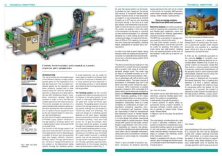
  • 1. TECHNICAL DIRECTORSTECHNICAL DIRECTORS28 29 Coping with flexible and umbilical laying: state of art capabilities Saipem S.p.A. Saipem S.p.A. Saipem S.p.A. SPE Italian Section Proj- ects, Facilities and Con- struction Technical Director Valerio Bregonzio Roberto Raglione Andrea Intieri INTRODUCTION The use of umbilicals and flexible pipes in the Offshore Industry is today a wide- spread option for the exploitation of oil and gas reservoirs. The increased con- fidence gained by the Operators with these products, coupled with a clear need to follow the trend for field devel- opments in deep and ultra deep waters, led the URF (Umbilicals, Risers, Flow- lines) contractors develop high-tech solutions in order to carry out safe and reliable operations with these products. This article provides an overview of a typical flexible and umbilical laying sys- tem also showing the main characteris- tics of a state of the art equipment such as the one onboard Saipem’s latest ves- sel, Normand Maximus. An overview of Flexible Laying Systems A Flexible Laying System comprises a storage system, a handling system and a laying system either horizontal (HLS) or vertical (VLS). The function of the storage system is to duly store the product(s) to be laid in the most appropriate manner depending on a number of factors such as product(s) type, size, weight, stiffness, minimum bending radius, storage specifications etc; it is also in charge of the delivery of the product to the downstream laying system through the handling system. A broad distinction can be made for these types of systems as follows: Reel Hub Drives, Carousels or Baskets. Oth- er minor systems are less important. In the following sections, a more detailed description of the first and second items will be provided. The handling system has the function to guide and contain the product prior to its ingress in the laying system. It may consist of rollerways with/without fric- tion pads with ramps and bends upon necessity. The guiding system serves to connect the storage system to the lay- ing system making sure the product is transferred safely and efficiently. The need and design of a handling system depends on the deck layout, available spaces and ancillary activities including termination handling, crane, wire rope access etc. To give an example, there are cases where the product is routed through the installation vessel deck and an articulated handling system is envis- aged, whereas where removable laying systems are considered, e.g. removable VLS tower and/or carousel, a handling system may not be necessary and the storage system may feed the laying sys- tem directly, optionally requiring minor modifications to the carousel spooling tower at the tensioner outlet. (Fig. 1) As said, the laying system can be broad- ly divided into two categories: horizontal and vertical. A horizontal flexible laying system consists of one or two tensioners arranged in a row horizontally or inclined (roughly up to 45°) and an over-boarding structure, mostly in the form of a chute (but wheels and freeboards may be pos- sible). A chute serves as a mean to launch the product by guiding it from the outlet of the tensioners all the way to a vertical or near-vertical inclination. It is normally designed as a fixed sliding surface with containmentedges.Itistypicaltofindsys- tems of 20Te to 75Te capacity, of compact size also featuring removability, allowing higher adaptability to variable deck con- figurations. In order to be able to exert higher laying tensions while not loading the product ex- cessivelyinaradialdirection(duetobend- ing forces), a vertical laying system (VLS) is more effective. The idea is to vertically arrange one or two tensioner(s) in a tower structure equipped with a product inlet chute at the top (al- ternative designs exist). The tower may be fixed or inclinable normally up to 10° with regards to the vertical position, offer- ing an advantage with stiff products and/ or shallower waters. The tower may be of permanent or removable type, but in the latter case with a lower tensioning capac- ity (around 100Te maximum): a suitable example is Saipem’s 90Te removable VLS tower, which can be efficiently installed on board of an Offshore Construction Vessel (OCV). Generally speaking, a VLS tower may be installed either on a moon-pool or on a side of the vessel or astern. From this standpoint, industrially, there is a wide variability of combinations of tower con- figurations, tensioning capacities, num- ber of tensioners and positions. Finally yet importantly, it shall be remembered that tensioners borne to handle flexible products are characterized normally by a 4-track design that allows maximizing contact length vs contact pressure. Being armed with special friction pads, contact lengths range between 1,5m-2m to 4,5m- 5m depending on capacity and design. Termination handling and opening/closing most often call for openable tensioners, where one track is mounted on a revolving structure or more simply for retractable tensioners. There is also a number of ancillary sys- tems, necessary for properly executing laying operations that will not be treated in this article: for example, A&R winches, under-tower openable tables, emergency clamps, tower cranes, routing arches. Focus on storage systems: Reel Hub Drives (RHD) and Carousels Reeldrivesystems are mobile equipment used for spooling and unspooling of rigid and flexible pipe, umbilicals, risers and other products for offshore applications, stored on multiple vertical reels. The RHD has a versatility to manage vari- ous products, stored in the reels. The reel drive system consists of two drive/lifting towers that lift the reel from its cradle for spooling. The towers can move along two skid beams, skidding from one spooling position to the next. At this location, it will pick up a reel for un- spooling. The system can be built with various reel interfaces suited for flexible pipes stan- dards. The system is completed by: • level winders to guide the products • control systems to satisfy safety re- quirements during product handling in operation activities. Control system per- mit to operate in Speed mode, Torque mode, Tension Mode • measure unit to calculate the products length. The main design considerations are: type of vessel / operating conditions, deck / system arrangement, available deck area, vessel deck loading capacity, gross weight of reel and product, reel diameter, reel width, interface details, maximum torque, angle or multiple reel handling, power drive: hydraulic / electric. Saipem is equipped with various of these system, able to manage all offshore prod- uctsandabletoworkworldwideforglobal energy projects. Basically, it consists of a motorized re- volving drum of vertical axis: the prod- uct is wound and packed under tension around the core assisted by a spooling tower, which acts also as a level winder, between the roof and the floor. It shall not be considered equivalent to the carousel basket or turntable mod- els, having them different features as re- minded above. Baskets (Fig. 4) work in a similar manner to Carousels except that they feature a storing system consisting of external containment walls/beams at the periphery (and in some instances with intermediate separate sectors along the radius) and an open-top design. The product is deployed into the basket (horizontal layering) from a loading arm allowing it to form a natural catenary under its self-weight and making it easy to manipulate within the basket. On the opposite, on a carousel, the product is spooled on under tension normally due to the high product stiffness, using a spool- ing unit that traverses vertically (vertical layering) between the carousel flanges. In a carousel the roof can be designed closed with suitable openings (normally 45°), ‘wireframed’ or in some cases may be absent. It has the function to support the product ends (while allowing its ac- cess underneath) prior to starting the storage operation and to ease and secureFig.1: Reel hub drive assembly Fig.2: Reel with product Fig.3: 20m OD carousel for flexible products Fig.4: Basket
  • 2. TECHNICAL DIRECTORSTECHNICAL DIRECTORS Andrea Intieri Andrea has more than ten years of experience in the energy industry and currently works in Saipem’s Mar- keting department. His interests include the genera- tion and development of new technical-commercial op- portunities in the offshore deep and ultra-deep water oil & gas developments and in the subsea processing technologies. Andrea holds a Master’s Degree with honours in Industrial Engineering from the Technical University of Milan, Italy, and a M.B.A. at the MIP School of Management, Italy. He is the SPE Italian Section Project, Facilities, Construc- tion Technical Director. Valerio Bregonzio Presently part of the Offshore R&D projects portfolio management unit, he has 14 years of experience in the offshore O&G industry. He committed many years to Research and Development, starting out as an R&D engineer in charge of the improvement of pipelay equipment and at a later stage became R&D project manager of technology innovation projects, growing also intellectual property management competences. He was also field engineer in the Green Stream pipelay project, involved in the offshore field activities. In the last years, before joining the Technology and innovation unit, he strengthened his technical background in the Asset department for about two years, in charge of the preparation and upgrade of flexible products lay systems. the packing operation. Bearing capacity of the roof structure plays an important role and can reach tens of tons. The floor supports the product weight, while trans- ferring it to the drum support structure (the physical interface with the vessel) of which a variety of designs exist. There is vast range of systems and designs avail- able on the market today that offer differ- ent features, but normally adjustable core diameterandroofheightarecommonfea- tures. Smallest carousels range slightly below 1,000Te payload capacity with outer diam- eters roughly around 10m while largest carousels can reach 5,000Te to 10,000Te and over 30m of outer diameter. Height rangesvarywidelyaswell,but4m-6mcan be considered a good reference. Last but not least, carousels can be permanently installed on a vessel (on deck or inside the ship’s body) or can be of removable type, i.e. they are not permanently installed on- board of a vessel for obvious reasons. Oneofthetypesofthelattermodelisaso- called “liftable carousel” (reported in Fig. 6), an advantageous model which Saipem has benefitted from since a few years. The underlying concept is to take advantage of the possibility to do a single lift of the en- tire(loaded)carousel(Fig. 6)thusavoiding otherwise costly or lengthy trans-pooling operations. The system comes with the additional flexibility to allow alternatively the single lift of the (loaded) drum. Focus on removable VLS Saipem 90Te Vertical Laying System is a removable piece of equipment where the main components are a Steel framework and a 90Te capacity tensioner. The steel framework, named the Lay Tower, has the function to accommodate a 90Te Tensioner (complete with top arch and work platforms) to perform umbilical, flexible pipe and cable laying in deepwa- ter. The whole structure may be divided into three main items: • a fixed 3D base frame bolted to the deck grillage, • a vertical frame hinged at the column base to the base and equipped two tilting cylinders. The frame and the attached tensioner may be tilted from vertical posi- tion in the range from 0° to 10° (inboard). A hydraulic centralizer and an emergency clamp (for emergency cases) are also fea- tured, • a box girder formed in a top circular arch whose function is to accommodate rollers upon which the product will run. A 4-track pipe tensioner is designed to perform the laying of flexible pipelines in the sea applying the required tension load at the required speed. State of art capabilities: Normand Maximus’ vertical laying system Offshore contractors offer a wide range of VLS capacities: beyond removable sys- tems, 100Te-120Te permanent systems exist as well as often in the 275Te-350Te range. Top-range systems belong to the permanent moon-pool tower type, typi- cally featuring a laying capacity of 550Te to 650Te. A good example of a state-of-art vessel is Saipem’s Normand Maximus (Fig. 8), equipped with a permanent VLS of 550Te capacity designed for the installation of flexible and rigid reeled products ranging from 50 mm to 700 mm outside diameter (up to 12” for rigid pipes OD). NormandMaximus,deliveredthisyearaf- ter final outfittings in Norway, is the result of an innovative design philosophy aimed at combining SURF installation with field development activities in ultra-deep wa- ters. This DP3 vessel is about 178 meters long, with a beam of 33 meters, a deck area of more than 2.500 m2 and is able to accommodate 180 people. Normand Maximus provides unique op- erational benefits in terms of versatility, as it is reconfigurable for multiple and simultaneous project tasks. It is designed to perform in the harshest environmental conditions thanks to its DNV Ice class C. It is also equipped with latest generation ROV, the Sonsub INNOVATOR 2.0. The VLS is positioned aft of the vessel moonpool and accommodates two 275Te tensioners, also being able to be inclined by +/-10˚. An under deck basket is locat- ed aft of the VLS for the storage of up to 3,800Te of flexible products. Moreover, additional removable Basket or RHD can be accommodate on Vessel deck to supply the product to the Tower. Conclusions The article provided an overview of a typ- ical flexible and umbilical laying system, describing its main components and char- acteristics and also showing the main fea- tures of a state of the art equipment such as the one onboard Saipem’s latest ves- sel, Normand Maximus. Fig.5: Spooling tower (in foreground) and 20m OD carousel Fig.6: Unique lift of loaded carousel and basement Fig.7: 90Te VLS on board of an OCV Fig.8: Saipem’s Normand Maximus at the naming cerimony Roberto Raglione Roberto has more than fifteen years of experience in the energy industry and currently works in Saipem’s Asset Department. His interests include the develop- ment of laying systems and new technical opportu- nities in the offshore oil & gas field. Roberto holds a Master’s Degree in Civil-structural Engineering from the Pisa University, Italy, and Master in Engineering and Contracting – Project Management at the MIP School of Management, Italy. He is the SPE Italian Section Project, Facilities, Construction member.