Analynk Industrial Wireless Demonstration System

For industrial and commercial installations. Test your potential wireless installation locations with Analynk's wireless demo unit, making sure the technology will work well at your site before ordering expensive process measurement and control instruments. The wireless demo kit includes a model A750 receiver and A753 transmitter both housed in NEMA 4 enclosures. The kit operates at 900 MHz with full 1W power. The A750 demo receiver includes an LCD indicator that allows monitoring of the A753 transmitter's signals; LEDs indicate the status of the two switch inputs on the transmitter. Other features include low battery indicators, an external RF connector for high gain antennas, and received signal strength mode (RSSI) mode. Both transmitter and receiver are water resistant. System can operate in simulation mode (demo mode) or standard mode for testing user inputs.

Recomendados
Recomendados
Mais conteúdo relacionado
Mais de Analynk Wireless, LLC
Mais de Analynk Wireless, LLC (8)
Último
Último (20)
Analynk Industrial Wireless Demonstration System
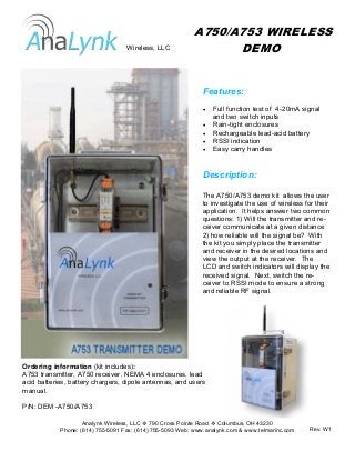
- 1. Analynk Wireless, LLC 790 Cross Pointe Road Columbus, OH 43230 Phone: (614) 755-5091 Fax: (614) 755-5093 Web: www.analynk.com & www.telmarinc.com Features: • Full function test of 4-20mA signal and two switch inputs • Rain-tight enclosures • Rechargeable lead-acid battery • RSSI indication • Easy carry handles Description: The A750/A753 demo kit allows the user to investigate the use of wireless for their application. It helps answer two common questions: 1) Will the transmitter and re- ceiver communicate at a given distance 2) how reliable will the signal be? With the kit you simply place the transmitter and receiver in the desired locations and view the output at the receiver. The LCD and switch indicators will display the received signal. Next, switch the re- ceiver to RSSI mode to ensure a strong and reliable RF signal. A750/A753 WIRELESS DEMO Ordering information (kit includes): A753 transmitter, A750 receiver, NEMA 4 enclosures, lead acid batteries, battery chargers, dipole antennas, and users manual. P/N: DEM -A750/A753 Wireless, LLC Rev. W1
- 2. Analynk Wireless, LLC 790 Cross Pointe Road Columbus, OH 43230 Phone: (614) 755-5091 Fax: (614) 755-5093 Web: www.analynk.com & www.telmarinc.com Operation Details In demo mode the A753 transmitter simulates inputs and transmits those to the receiver; the receiver responds ac- cordingly. The 4-20mA signal is auto- matically ramped up and down in 1mA increments. Switch 1 and 2 actuations are simulated at 8mA and 12mA. The output of the 4-20mA signal and switch states can be viewed on the A750’s LCD and switch status LEDS, respec- tively. The receiver has an optional RSSI mode. In this mode the received signal strength is displayed on the LEDs. An indication of field strength is deter- mined by the number of on LEDs, The receiver can operate in normal mode. In this mode the transmitter’s input can accept any 4-20 mA signal and up to two switch contacts (dry or wet). All modes of operation can be accessed via the front door of the receiver. Both transmitter and receiver come with a remov- able dipole antenna. Any antenna that accepts a RPSMA connector may be used. High Low