SlideShare uma empresa Scribd logo
1 de 1
Baixar para ler offline
DESIGN OF MACHINERY 3rd Ed.                             by ROBERT L. NORTON                              © McGraw-Hill 2004


                                                                             250
                                  43                              184
                                                                                                        17
                  43 typ.           90°     A1             B1
                                                                               45°
          86 typ.              17
                               typ.              52 typ.                         A2                            145

                                                 86 typ.                                  B2

                                                                                                   0°

            180                                                                            A3
                                                 base

                                                                                           B3


                                                 167                                    all dimensions in mm
FIGURE P3-13
Problems 3-46 to 3-48


  3-46   Design a fourbar linkage to move the object in Figure P3-13 from position 1 to 2 using
         points A and B for attachment. Add a driver dyad to limit its motion to the range of
         positions designed making it a sixbar. All fixed pivots should be on the base.
  3-47   Design a fourbar linkage to move the object in Figure P3-13 from position 2 to 3 using
         points A and B for attachment. Add a driver dyad to limit its motion to the range of
         positions designed making it a sixbar. All fixed pivots should be on the base.
  3-48   Design a fourbar linkage to move the object in Figure P3-13 through the three positions
         shown using points A and B for attachment. Add a driver dyad to limit its motion to the
         range of positions designed making it a sixbar. All fixed pivots should be on the base.

Mais conteúdo relacionado

Mais de Alane1967

Velocidad metodo grafico ci
Velocidad metodo grafico ciVelocidad metodo grafico ci
Velocidad metodo grafico ciAlane1967
 
Fundamentos de cinematica
Fundamentos de cinematicaFundamentos de cinematica
Fundamentos de cinematicaAlane1967
 
Aceleración de coriolis
Aceleración de coriolisAceleración de coriolis
Aceleración de coriolisAlane1967
 
Leccion4 analisis cinematico metodo grafico
Leccion4 analisis cinematico metodo graficoLeccion4 analisis cinematico metodo grafico
Leccion4 analisis cinematico metodo graficoAlane1967
 
Fundamentos de cinematica
Fundamentos de cinematicaFundamentos de cinematica
Fundamentos de cinematicaAlane1967
 
TEORÍA BÁSICA DE MOTORES DE COMBUSTIÓN INTERNA
TEORÍA BÁSICA DE MOTORES DE COMBUSTIÓN INTERNATEORÍA BÁSICA DE MOTORES DE COMBUSTIÓN INTERNA
TEORÍA BÁSICA DE MOTORES DE COMBUSTIÓN INTERNAAlane1967
 
Módulo de mecanismos
Módulo de mecanismosMódulo de mecanismos
Módulo de mecanismosAlane1967
 

Mais de Alane1967 (10)

Fig p3 18
Fig p3 18Fig p3 18
Fig p3 18
 
Fig p3 17
Fig p3 17Fig p3 17
Fig p3 17
 
Fig p3 16
Fig p3 16Fig p3 16
Fig p3 16
 
Velocidad metodo grafico ci
Velocidad metodo grafico ciVelocidad metodo grafico ci
Velocidad metodo grafico ci
 
Fundamentos de cinematica
Fundamentos de cinematicaFundamentos de cinematica
Fundamentos de cinematica
 
Aceleración de coriolis
Aceleración de coriolisAceleración de coriolis
Aceleración de coriolis
 
Leccion4 analisis cinematico metodo grafico
Leccion4 analisis cinematico metodo graficoLeccion4 analisis cinematico metodo grafico
Leccion4 analisis cinematico metodo grafico
 
Fundamentos de cinematica
Fundamentos de cinematicaFundamentos de cinematica
Fundamentos de cinematica
 
TEORÍA BÁSICA DE MOTORES DE COMBUSTIÓN INTERNA
TEORÍA BÁSICA DE MOTORES DE COMBUSTIÓN INTERNATEORÍA BÁSICA DE MOTORES DE COMBUSTIÓN INTERNA
TEORÍA BÁSICA DE MOTORES DE COMBUSTIÓN INTERNA
 
Módulo de mecanismos
Módulo de mecanismosMódulo de mecanismos
Módulo de mecanismos
 

Fig p3 13

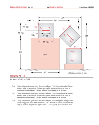
  • 1. DESIGN OF MACHINERY 3rd Ed. by ROBERT L. NORTON © McGraw-Hill 2004 250 43 184 17 43 typ. 90° A1 B1 45° 86 typ. 17 typ. 52 typ. A2 145 86 typ. B2 0° 180 A3 base B3 167 all dimensions in mm FIGURE P3-13 Problems 3-46 to 3-48 3-46 Design a fourbar linkage to move the object in Figure P3-13 from position 1 to 2 using points A and B for attachment. Add a driver dyad to limit its motion to the range of positions designed making it a sixbar. All fixed pivots should be on the base. 3-47 Design a fourbar linkage to move the object in Figure P3-13 from position 2 to 3 using points A and B for attachment. Add a driver dyad to limit its motion to the range of positions designed making it a sixbar. All fixed pivots should be on the base. 3-48 Design a fourbar linkage to move the object in Figure P3-13 through the three positions shown using points A and B for attachment. Add a driver dyad to limit its motion to the range of positions designed making it a sixbar. All fixed pivots should be on the base.