

Recomendados
Mais conteúdo relacionado
Mais de Akshay Sharma
Mais de Akshay Sharma (15)
Último
Último (20)
Est 10
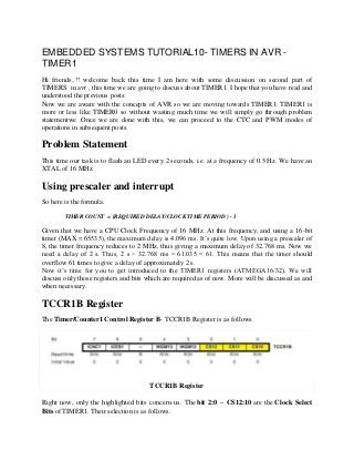
- 1. EMBEDDED SYSTEMS TUTORIAL10- TIMERS IN AVR TIMER1 Hi friends..!! welcome back this time I am here with some discussion on second part of TIMERS in avr , this time we are going to discuss about TIMER1. I hope that you have read and understood the previous posts: Now we are aware with the concepts of AVR so we are moving towards TIMER1. TIMER1 is more or less like TIMER0 so without wasting much time we will simply go through problem statementwe .Once we are done with this, we can proceed to the CTC and PWM modes of operations in subsequent posts. Problem Statement This time our task is to flash an LED every 2 seconds, i.e. at a frequency of 0.5 Hz. We have an XTAL of 16 MHz. Using prescaler and interrupt So here is the formula. TIMER COUNT = (REQUIRED DELAY/CLOCK TIME PERIOD ) - 1 Given that we have a CPU Clock Frequency of 16 MHz. At this frequency, and using a 16-bit timer (MAX = 65535), the maximum delay is 4.096 ms. It’s quite low. Upon using a prescaler of 8, the timer frequency reduces to 2 MHz, thus giving a maximum delay of 32.768 ms. Now we need a delay of 2 s. Thus, 2 s ÷ 32.768 ms = 61.035 ≈ 61. This means that the timer should overflow 61 times to give a delay of approximately 2 s. Now it’s time for you to get introduced to the TIMER1 registers (ATMEGA16/32). We will discuss only those registers and bits which are required as of now. More will be discussed as and when necessary. TCCR1B Register The Timer/Counter1 Control Register B- TCCR1B Register is as follows. TCCR1B Register Right now, only the highlighted bits concern us. The bit 2:0 – CS12:10 are the Clock Select Bits of TIMER1. Their selection is as follows.
- 2. Clock Select Bits Description Since we need a prescaler of 8, we choose the third option (010). TCNT1 Register The Timer/Counter1 - TCNT1 Register is as follows. TCNT1 Register It is 16 bits wide since the TIMER1 is a 16-bit register. TCNT1H represents the HIGH byte whereas TCNT1L represents the LOW byte. The timer/counter value is stored in these bytes. TIMSK Register The Timer/Counter Interrupt Mask Register – TIMSK Register is as follows.
- 3. TIMSK Register As we have discussed earlier, this is a common register for all the timers. The bits associated with other timers are greyed out. Bits 5:2 correspond to TIMER1. Right now, we are interested in the yellow bit only. Other bits are related to CTC mode which we will discuss later. Bit 2 – TOIE1 – Timer/Counter1 Overflow Interrupt Enable bit enables the overflow interrupt of TIMER1. We enable the overflow interrupt as we are making the timer overflow 61 times (refer to the methodology section above). TIFR Register The Timer/Counter Interrupt Flag Register – TIFR is as follows. TIFR Register Once again, just like TIMSK, TIFR is also a register common to all the timers. The greyed out bits correspond to different timers. Only Bits 5:2 are related to TIMER1. Of these, we are interested in Bit 2 – TOV1 – Timer/Counter1 Overflow Flag. This bit is set to ’1′ whenever the timer overflows. It is cleared (to zero) automatically as soon as the corresponding Interrupt Service Routine (ISR) is executed. Alternatively, if there is no ISR to execute, we can clear it by writing ’1′ to it. Code Now its time for coding its too easy like TIMER0, if you have not gone through TIMER0 please read TIMER0 tutorial first otherwise it will be a bit tough for you. /* * TIMER1.c * * Created: 1/28/2013 1:59:29 AM * Author: ABHILASH */ #include <avr/io.h> #include <avr/interrupt.h> // global variable to count the number of overflows
- 4. volatile uint8_t timer_overflow; // initialize timer, interrupt and variable void timer1_init() { // set up timer with prescaler = 8 TCCR1B |= (1 << CS11); // initialize counter TCNT1 = 0; // enable overflow interrupt TIMSK |= (1 << TOIE1); // enable global interrupts sei(); // initialize overflow counter variable timer_overflow = 0; } // TIMER1 overflow interrupt service routine // called whenever TCNT1 overflows ISR(TIMER1_OVF_vect) { // keep a track of number of overflows timer_overflow++; // check for number of overflows here itself // 61 overflows = 2 seconds delay (approx.) if (timer_overflow >= 61) // NOTE: '>=' used instead of '==' { PORTC ^= (1 << 0); // toggles the led // no timer reset required here as the timer // is reset every time it overflows timer_overflow = 0; // reset overflow counter } } int main(void) { // connect led to pin PC0 DDRC |= (1 << 0); // initialize timer timer1_init(); // loop forever while(1) { // do nothing // comparison is done in the ISR itself } }
- 5. So friends it was all about TIMER1 in AVR , in case of any query doubt or critical view just leave a comment here . in our next tutorial we will discuss about TIMER2 , till then bye…!!