vPC techonology for full ha from dc core to baremetel server.
•
0 gostou•429 visualizações

Full HA Redundancy from Data Center Core to Server in OpenStack cloud Environment.

Recomendados
Recomendados
Mais conteúdo relacionado
Mais procurados
Mais procurados (20)
Semelhante a vPC techonology for full ha from dc core to baremetel server.
Semelhante a vPC techonology for full ha from dc core to baremetel server. (20)
Mais de Ajeet Singh
Mais de Ajeet Singh (6)
Último
Último (20)
vPC techonology for full ha from dc core to baremetel server.
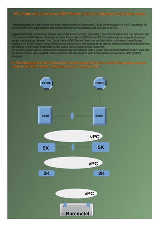
- 1. I had designed the Leaf-Spine with core deployment in Openstack Cloud Infrastructure. In a vPC topology, all links between the aggregation and access layers are forwarding and are part of a vPC. Gigabit Ethernet connectivity makes use of the FEX concept. Spanning Tree Protocol does not run between the Cisco Nexus 5000 Series Switches and the Cisco Nexus 2000 Series FEXs. Instead, proprietary technology keeps the topology between the Cisco Nexus 5000 Series Switches and the fabric extenders free of loops. Adding vPC to the Cisco Nexus 5000 Series Switches in the access layer allows additional load distribution from the server to the fabric extenders to the Cisco Nexus 5000 Series Switches. An existing Cisco Nexus 7000 Series Switch can be replaced with a Cisco Nexus 9500 platform switch with one exception: Cisco Nexus 9000 Series Switches do not support vPC active-active or two-layer vPC (eVPC) designes. In This Design have full HA from Core to Baremetel Server for cloud Enviorment and weIn This Design have full HA from Core to Baremetel Server for cloud Enviorment and we need to also NICs Bond in Baremetel server ends for vPC.need to also NICs Bond in Baremetel server ends for vPC. vPC Design with Cisco Nexus 9500 Platform in the Core OpenStack Cloud Data CentervPC Design with Cisco Nexus 9500 Platform in the Core OpenStack Cloud Data Center 2K 2K CORE CORE 9508 9508 5K 5K vPCvPC vPCvPC vPC BaremetelBaremetel
- 2. ConsolidationConsolidation:-:- Most data centers are the result of aconsolidation process that was facilitated by the availability of bandwidth to connect remote locations to centralized data centers. During the consolidation process, enterprises and service providers simplified the network and the storage infrastructure by adopting topologies that take advantage of virtuallocal area networks (VLANs) and the virtual storage area network (VSAN) technology.The same process of simplification is currently happening on the computing nodes. It involves both physical consolidation by means of blade enclosures and server virtuallization at the operating system(OS) level, which makes it possible to run multiple instances of variouss operating systems on the same physical machine. ●● End of the Row and Top of the Rack :-End of the Row and Top of the Rack :- Most existing data centers are deployed according to two design philosophies: End-of-the-row topologies:This topology consists of large, director-class switching devices at the end of each row of servers. End-of-the-row topologies require significant cabling bulk to be carried from all server racks to the network rack. The main advantage of end-of-the-row topologies is the fact that fewer configuration points (switches) control a large number of server port. ●● Top-of-the-rack topologies:-Top-of-the-rack topologies:- This topology consists of one-rack unit (1RU) or 2RU devices at the top or bottom of each server rack, providing server (or blade server) connectivity within each rack and aggregated ba switch at the aggregation layer. Top-of-the-rack topologies are more efficient in terms of cabling because fewer cables are required from each rack to the end-of-the-row switch.
- 3. On the other hand, top-of-the-rack topologies require more switches than end-of-the-row topologies require for the same number of switch ports,which increases the management Burden. Layer 2 Layer 2 has been well known for its flexibility in providing VLAN access anywhere in the data center. Layer 2 is alsoknown for the potential impact of Layer2 loops. Overall, the benefits of Layer 2 largely outweigh the risk of loops, somost environments today consist of Layer 2 pods or even have multiple pods that are part of the same Layer 2 domain.A Layer 3 boundary is always recommended to connect servers to clients. The placement of the Layer 3 boundarydefines the scale of the Layer2 domain, with the result that the size of Layer 2 domains varies enormously between Customers. ●● All Links Forwarding:-All Links Forwarding:- The next-generation data center provides the ability to use all links in the LAN topology by taking advantage of technologies such as virtual PortChannels (vPCs). VPCs enable full, cross-sectional bandwidth utilization among LANswitches, as well as between servers and LAN switches. ● Server Connectivity at 10 Gigabit Ethernet:- Most rackable servers today include redundant LAN-on-motherboard (LOM/iLO) interfaces for management, anintegrated-lights-out (iLO) standard-based port, and one or more GigabitEthernet interfaces, and redundant host busadapters (HBA). The adoption of 10 Gigabit Ethernet on the server simplifies server configuration by reducing The number of network adapters and providing enough bandwidth for virtualized servers. The data center design can befurther optimized with the use of Fibre Channelover Ethernet (FCoE) to build a unified fabric.Cost-effective 10 Gigabit Ethernet connectivity can be achieved by using copper twinax cabling with Small Form-
- 4. by using copper twinax cabling with Small Form-Factor Pluggable Plus (SFP+) connectors.A rackable server configured for 10 Gigabit Ethernet connectivity may have an iLO port, a dual- LOM, and a dual-port10 Gigabit Ethernet adapter (for example, a converged network adapter). This adapter would replace multiple QuadGigabit Ethernet adapters and, in case the adapter is also a Cisco Network Adapter, it would also replace an HBA. ●Fabric Extender:- Fabric extender technology simplifies the management of the many LAN switches in the data center by aggregating them in groups of 10 to 12 under the same management entity. In its current implementation, Cisco Nexus 2000 Series Fabric Extenders can be used to provide connectivity across 10 to 12 racks that are all managed from a single switching configuration point, thus bringing together the benefit s of top-of-the-rack and end-of-the-row topologies. Guys Please follow the below config :-Guys Please follow the below config :- version 7.0(2)N1(1) hostname Nexus 5K(Primary) feature telnet cfs ipv4 distribute cfs eth distribute feature ospf feature bgp feature interface-vlan feature hsrp feature lacp feature vpc feature lldp feature fex
- 5. banner motd #Nexus 6000 Switch # ip domain-lookup ip access-list 10 10 permit ip any any system qos service-policy type qos input fcoe-default-in-policy service-policy type queuing input fcoe-default-in-policy service-policy type queuing output fcoe-default-out-policy service-policy type network-qos fcoe-default-nq-policy fex 1 pinning max-links 1 description "FEX01" fex 2 pinning max-links 1 description "FEX02" fex 3 pinning max-links 1 description "FEX03" vlan 1 vlan7 name SW_MGMT vlan10 name iLO route-map Connected_Subnet permit 10 vrf context management vpc domain 30 peer-switch role priority 50 system-priority 100 peer-keepalive destination 10.x.x.y delay restore 150 auto-recovery
- 6. interface Vlan1 interface Vlan7 description **** no shutdown ip address ip router ospf 1 area 0.0.0.1 hsrp 50 preempt delay minimum 10 priority 50 timers 1 3 ip (ip Address) interface Vlan10 description **** no shutdown ip address (a.b.c.d) ip router ospf 1 area 0.0.0.1 hsrp 50 preempt delay minimum 10 priority 50 timers 1 3 ip (Floating ip) interface port-channel1 description ***VPC-Peer_Link-*** switchport mode trunk spanning-tree port type network speed 10000 vpc peer-link interface port-channel1 description ****** switchport mode fex-fabric switchport trunk allowed vlan10 fex associate 1 vpc 1
- 7. interface port-channel2 description ****** switchport mode fex-fabric switchport trunk allowed vlan10 fex associate 2 vpc 2 interface port-channel3 description ****** switchport mode fex-fabric switchport trunk allowed vlan10 fex associate 3 vpc 3 interface Ethernet1/1 description ****** switchport mode fex-fabric switchport trunk allowed vlan10 fex associate 1 Channel-group 1 interface Ethernet1/2 description ****** switchport mode fex-fabric switchport trunk allowed vlan10 fex associate 2 channel-group 2 interface Ethernet1/3 description ****** switchport mode fex-fabric switchport trunk allowed vlan10 fex associate 3 channel-group 3
- 8. interface Ethernet1/25 description ****** switchport mode trunk channel-group 1 mode active interface Ethernet1/26 description ****** switchport mode trunk channel-group 1 mode active interface Ethernet1/48 description ****** no switchport ip address e.f.g.h/30 ip ospf network point-to-point ip router ospf 1 area 0.0.0.1 interface mgmt0 vrf member management interface Ethernet101/1/1 description ****** switchport access vlan 3 interface Ethernet101/1/2 description ****** switchport access vlan 3 interface Ethernet101/1/3 description ****** switchport access vlan7 line console line vty boot kickstart bootflash:/n6000-uk9-kickstart.7.0.2.N1.1.bin boot system bootflash:/n6000-uk9.7.0.2.N1.1.bin router ospf 1 redistribute direct route-map Connected_Subnet poap transit
- 9. version 7.0(1)N1(1) hostname Nexus 5k (Secondary)hostname Nexus 5k (Secondary) feature telnet cfs eth distribute feature ospf feature bgp feature interface-vlan feature hsrp feature lacp feature vpc feature lldp feature fex banner motd #Nexus 6000 Switch # ip domain-lookup ip access-list 10 10 permit ip any any fex 1 pinning max-links 1 description "FEX01" fex 2 pinning max-links 1 description "FEX02" fex 3 pinning max-links 1 description "FEX03" vlan 1 vlan7 name ***SWITCH-MGMT*** Vlan10 name ******
- 10. route-map Connected_subnet permit 10 vrf context management vpc domain 30 role priority 100 system-priority 100 peer-keepalive destination (VPC Peer IP) delay restore 150 Auto-recovery interface Vlan1 interface Vlan7 description **SW-MGMT** no shutdown ip address X.Y.Z.Z/24 ip router ospf 1 area 0.0.0.1 hsrp 50 preempt delay minimum 10 priority 30 timers 1 3 ip (Floating IP) interface Vlan10 description **** no shutdown ip address A.B.C.D/23 ip router ospf 1 area 0.0.0.1 hsrp 50 preempt delay minimum 10 priority 30 timers 1 3 ip (Floating IP) interface port-channel1 description ***VPC-PAIRLINK-*** switchport mode trunk spanning-tree port type network Speed 10000 vpc peer-link
- 11. interface port-channel1 description ****** switchport mode fex-fabric switchport trunk allowed vlan10 fex associate 1 vpc 1 interface port-channel2 description ****** switchport mode fex-fabric switchport trunk allowed vlan10 fex associate 2 Vpc 2 interface port-channel3 description ****** switchport mode fex-fabric switchport trunk allowed vlan10 fex associate 3 vpc 3 interface Ethernet1/1 description ****** switchport mode fex-fabric switchport trunk allowed vlan10 fex associate 1 Channel-group 1 interface Ethernet1/2 description ****** switchport mode fex-fabric switchport trunk allowed vlan10 fex associate 2 channel-group 2
- 12. interface Ethernet1/3 description ****** switchport mode fex-fabric switchport trunk allowed vlan10 fex associate 3 Channel-group 3 interface Ethernet1/25 description ****** switchport mode trunk channel-group 1 mode active interface Ethernet1/26 description ****** switchport mode trunk channel-group 1 mode active interface Ethernet1/48 description ****** no switchport ip address A>B>C>D/30 ip ospf network point-to-point ip router ospf 1 area 0.0.0.1 interface mgmt0 vrf member management line console line vty boot kickstart bootflash:/n6000-uk9-kickstart.7.0.1.N1.1.bin boot system bootflash:/n6000-uk9.7.0.1.N1.1.bin router ospf 1 redistribute direct route-map Connected_subnet poap transit
- 13. Thank You Guys for Visit my refer GuideThank You Guys for Visit my refer Guide Cheers, Ajeet Singh Contact No:- +91 992039357 Linkedin:-https://in.linkedin.com/pub/ajeet-singh/3a/b42/895 Twitter:-@ajeet0537 Blog:-https://ajeets1.blogspot.in Facebook:-https://www.facebook.com/Technical.Rapiist