2 compression
•Transferir como DOC, PDF•
3 gostaram•1,058 visualizações

Material (III) Dr/ Ahmed Mohamed Hassan

Recomendados
Mais conteúdo relacionado
Mais procurados
Mais procurados (20)
Destaque
Semelhante a 2 compression
Semelhante a 2 compression (20)
Mais de Ahmed Gamal
Mais de Ahmed Gamal (20)
Último
Último (20)
2 compression
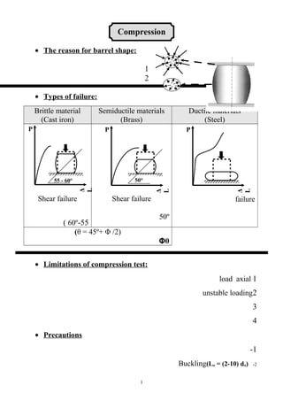
- 1. Compression • The reason for barrel shape: 1 2 • Types of failure: Brittle material (Cast iron) Semiductile materials (Brass) Ductile materials (Steel) Shear failure 55-60º( Shear failure 50º failure (θ = 45º+ Φ /2) θΦ • Limitations of compression test: 1load axial 2unstable loading 3 4 • Precautions 1- 2-)Lо = (2-10) dо(Buckling 1 P Δ L 55 - 60° Δ L P 50° P Δ L
- 2. Pp.l Aо Pmax Aо Aо Lо ½ Pp.l X ∆Lp.l Aо Lо ⅔ Pmax X ∆Lmax L D L D 3 43-14(° • The use of spherical bearing blocks 1 2 • UseSizeSpecimen For bearing materialsL = 0.9DShort Determination of compressive strengthL = (2- 3)Dmedium Drawing the P- ΔL and determining the Young's modulus L = (8-10)DLong 1.10 2.1.5Strength )L/D > 2) to provide suitable middle region free from end restarints σp.lElastic (proportional) limit stress σmaxUltimate compressive strength M.RModulus of resilience M.T. Modulus of toughness 2 Spherical block Specimen Machine head
- 3. ∆Lf Lо ε1 σ1 2 φ % Contraction tan βSecant modulus at stress σ1 • Prove that (θ = 45º+ ) θ Friction force = x =μF μtan Φ F= (Pcos θ) (tan Φ) τ = force/area Area = A/ cos θ τ = (cos θ/A)[Psin θ - Pcos θ tan Φ] τ = (P/A)[ sin θ cos θ - cos 2θ tan Φ] τ = (P/A)[ ½ sin 2θ - cos 2θ tan Φ] θτ dτ/dθ = 0 cos 2θ +2 sin θ cos θ tan Φ = 0 3 N μ N θ θ P P P sin θ P cosθ tanφ P cos θ
- 4. 2 φ cos 2θ + sin 2θ tan Φ = 0 cos 2θ / sin 2θ + tan Φ = 0 -tan Φ = cot 2θ -tan Φ = tan (90 - 2θ) θ = 45º+ Φ ( ) Determine the relative displacement of points A and D of a steel rod of variable cross section area shown in Fig. when subjected to 4 concentrated load forces P1, P2, P3, and P4 . (Es = 200 GPa). Cross sectional area of AB and CD = 0.001 m2 , and BC = 0.002 m2 ΔL = A1 = 0.001 m2 A2 = 0.002 m2 A3 = 0.001 m2 Tension Compression Tension 4 P1 = 100 KN 2m P 4 NK 001 = P 3 NK 001 = P 2 NK 001 = A B C D 1m 5.1m L P A E P 1 L 1 A E 1 P 2 L 2 A E 2 P 3 L 3 A E 3 01 x 2 x 001 3 00201 x 9 100.0 x 05101 x 1 x 3 01 x 002 9 200.0 x 01 x 5.1 x 05 3 00201 x 9 100.0 x NK001 2m NK 05NK 051NK 051NK001 1m 5.1m NK 05
- 5. ΔL1 = ΔL1 = ΔL2 = ΔL2 = ΔL3 = ΔL3 = ΔL1 = 0.001 m ΔL2 = 0.000375 ΔL3 = 0.000375 ΔLtot = ΔL1 + ΔL3 – ΔL2 = 0.001 m (Tension) ( ) A brass bar having cross-sectional area of 10 cm2 is subjected to axial forces as shown in Fig. 1. Find the total change in length of the bar. Eb = 1.05 x 10⁶ Kg/cm2 ΔL = Tension Compression Compression 5 5000 Kg 60 cm 1000 Kg2000 Kg8000 Kg 100 mc 021mc L P A E P 1 L 1 A E 1 P 2 L 2 A E 2 P 3 L 3 A E 3 06 x 0005 50.101 x 6 01 x 0003001 x 50.101 x 6 01 x 021 x 0001 50.101 x 6 01 x gK 0005 06mc gK 0001gK 0003gK 0003 gK0005 001 mc 021mc gK 0001
- 6. ΔL1 = ΔL1 = ΔL2 = ΔL2 = ΔL3 = ΔL3 = ΔL1 = 0.0286 cm ΔL2 = 0.0286 cm ΔL3 = 0.0114 cm ΔLtot = ΔL1 + ΔL3 – ΔL2 = 0.0114 cm ( ) A member formed by connecting a steel bar to an aluminum bar is shown in the Fig. (3). Assuming that the bars are presented from buckling sidewise, calculate the magnitude of force P that will cause the total length of the member to decrease 0.25 mm. The values of elastic modulus for steel and aluminum are 210 KN/mm2 and 70 KN/mm2 respectively. ΔL = ΔLtot = ΔLs + ΔLAl = 0.25 6 P L E A 300 P 21005 x 05 x P 083 07001 x 001 x rab munimulA 001001 x rab leetS 0505 x P 083 mm mm 003
- 7. + = 0.12 P = 224.4 kg ( ) A bar ABC shown in the Fig. (2) consists of two parts AB and BC, each part being 1 meter long and having cross-section area of 2 cm2 and 3 cm2 respectively. The bar is suspended from A and there is a rigid horizontal support at 2.001 m from A. A force of 10 tons acting vertically downwards is applied at B. Determine (i) the reaction produced by the rigid horizontal support, (ii) the stresses in parts AB and BC of the bar. Take E = 2 x 10⁶ kg/cm2 (i) ΔL = ΔLtot = ΔLAB - ΔLBC = 0.001 + = 0.1 7 A A1 = 2 cm2 10 not 1m m 1 1mm A 2 mc 3 = 2 B C L P A E 001 x (R – 01) 201 x 6 2 x 001 x R 201 x 6 3 x noisserpmoC R R noisneT 01- R 01- R PBA A о 6.3 – 01 2 PCB A о 6.3 3
- 8. R = 3.6 kg (ii) σAB = = = 3.2 kg/cm2 σBC = = = 1.2 kg/cm2 ( ) A reinforced concrete column of cross-section is shown in the figure. The section is reinforced by four steel bars of 20 mm diameter each. If the column carry a load of 80 ton, find the load carried by the steel and concrete, the contraction in the column is 0.5 mm. Find also the stress on the steel bars and on the concrete. Es = 206 GPa, Ec = 14 GPa Ptot = 80 ton = PS + PC ΔL = 0.5 mm ΔL = ΔLtot = ΔLS = ΔLC AS = 4 x (π/4)(20)2 = 1257 mm2 AC = (400 x 600) – 1257 = 238743 mm2 8 40 mc 06 mc P S A S P s L 60201 x 3 7521 x P c L 4101 x 3 347832 x L P A E 7.5 7521 P C A C 3.47 347832
- 9. Pmax Aо 250 177 0.05x 100 25 ∆Lf Lо % 455 0.0075/25 σ ε 0.5 = = PS L = 129.5 x 10⁶ PC L = 1671.2 x 106 PS = 0.07749 PC PC = 74.3 ton PS = 5.7 ton σS = = = 4.5 x 10⁻³ ton / mm2 σC = = = 3.11 x 10⁻⁴ ton / mm2 ( ) A concrete cylinder 15 cm in diameter with a gauge length of 25 cm is used to obtain the stress-strain diagram in compression. If the specimen failed at a load of 250 KN and a total contraction of 0.05 cm, determine the following: (i) The ultimate strength (ii) The percentage contraction (iii) The secant modulus at a stress of 455 N/cm2 and contraction of 0.0075cm D = 15 cm L = 25 cm Pmax = 250 KN ΔLmax = 0.05 cm Ao = (π/4) (15)2 = 177 cm2 i) Ultimate strength σmax = = = 1.41 KN/cm2 ii) % Contraction = = = 0.2% iii) tan α = = = 1516.7 KN/ /cm2 9
- 10. ( ) The following data were obtained in the compression test of a cast iron cylindrical specimen 35 mm diameter and 250 mm height. The load (P) and the corresponding decrease in height (h) were as follows: P (KN) 0 27 68 102 136 203 272 h(mm) 0 0.056 0.14 0.208 0.28 0.457 0.71 Draw the ordinary stress-strain diagram and determine the following: (i) The crushing stress (ii) The initial tangent modulus (iii) The secant modulus at a stress of 2100 kg/cm2 (iv) Modulus of toughness Lо = 250 mm Aо = π/4 (35)2 = 962 mm2 σ (N/mm2 ) 0 28 71 106 141.4 211 282.7 ε x 10-4 0 2.24 5.6 8.3 11.2 18.3 28.4 100 50 100 150 200 250 300 0 5 10 15 20 25 30 σ ε
- 11. Pmax Aо 272 962 εp.l σp.l ∆Lp.l x Aо Pp.l x Lо 0.056 x 962 27x 250 210 18.75 x 10⁻⁴ σ ε i) The crushing stress σmax = = = 0.283 KN/mm2 ii) Modulus of elasticity E = = = = 125.3 KN/mm2 iii) The secant modulus σ = 2100 kg/cm2 = 210 N/mm2 From drawing (ε) = 18.75 x 10⁻⁴ tan α = = = 11.2 x 10⁴ N/ /mm2 ( ) A compression test was carried out on a cast iron cylindrical specimen of 3.4 cm diameter and 25 cm length. The loads and corresponding decrease in height were as follow: Load (KN) 0 27 68 102 136 203 272 Decrease in height (mm) 0 0.056 0.14 0.208 0.28 0.457 0.71 Draw the ordinary stress-strain diagram and determine the following: (i) The fracture stress (ii) The modulus of elasticity (iii) The secant modulus at a stress of 21 KN/cm2 Lо = 25 cm Aо = π/4 (3.4)2 = 9.1 cm2 σ (KN/cm2 ) 0 2.9 7 7.47 11.2 14.94 22.3 29.89 ε x 10-3 0 2.2 4 5.6 8.3 11.2 18.3 28.4 11 σ ε 0 5 10 15 20 25 30 35 0 5 10 15 20 25 30
- 12. Pmax Aо 272 9.1 εp.l σp.l ∆Lp.l x Aо Pp.l x Lо 0.056 x 9.1 27x 25 21 17.25 x 10⁻³ σ ε 0 5 10 15 20 25 30 0 5 10 15 20 25 30 35 40 σ ε i) The fracture stress σmax = = = 29.9 KN/cm2 ii) Modulus of elasticity E = = = = 1324.6 KN/cm2 iii) The secant modulus σ = 2100 kg/cm2 = 21 KN/cm2 From drawing (ε) = 17.25 x 10⁻³ tan α = = = 1217.4 KN/cm2 ( ) A compressive test was carried out on a brass cylinder of 10 cm2 cross- section area and gauge length of 200 mm. The load and corresponding decrease in height were as follow: Load (Kg) 0 2700 6750 10100 12500 17500 20000 27000 Decrease in height (mm) 0 0.055 0.1375 0.205 0.255 0.365 0.445 0.700 Draw the stress-strain diagram and find: (a) Ultimate compressive strength (b) Modulus of resilience (c) Elastic compressive strength (d) The modulus of elasticity (e) Modulus of toughness (f) Contraction % (g) Secant modulus at a stress of 2400 Kg/cm2 Lо = 200 mm Aо = 1000 mm2 σ (Kg/mm2 ) 0 2.7 6.75 10.1 12.5 17.5 20 27 ε x 10-4 0 2.7 5 6.875 10.25 12.75 18.25 22.25 35 12
- 13. 2400 29 x 10-4 σ ε 0.7x 100 200 ∆Lf Lо % Aо x Lо ⅔ Pmax x ∆Lmax 1000 x 200 ⅔ x 27000 x 0.7 Pmax Aо 27000 1000 εp.l σp.l ∆Lp.l x Aо Pp.l x Lо 0.365 x 1000 17500x 200 Pp.l Aо 17500 1000 Aо x Lо ½Pp.l x ∆Lp.l 1000 x 200 ½ x 17500 x 0.365 (a) Ultimate compressive strength σmax = = = 27 Kg/mm2 (b) Modulus of resilience (M.R.) = = = 0.016 Kg/mm2 (c) Elastic compressive strength σP.l = = = 17.5 Kg/mm2 (d) Modulus of elasticity E = = = = 9.6 ton/mm2 (e) Modulus of toughness = = = 0.063 Kg/mm2 (f) % Contraction = = = 0.35% (g) The secant modulus σ = 2400 kg/cm2 = 24 kg/mm2 From drawing (ε) = 29 x 10-4 tan α = = = 8.3 x 10⁵ Kg/cm2 13
- 14. ( ) A compression test was carried out on a concrete cylinder of 20 cm in diameter and gage length of 25 cm. The following data load and were recorded: Load, ton 0 1.8 5.4 9 12.6 14.4 18 21.5 23.4 25.2 26 27 ∆L, mm x 10-2 0 0.66 2.05 4 6.6 8.3 15.4 23.4 29.7 40 47 59.5 Draw the stress-strain diagram and find: a- Ultimate compressive strength b- The initial modulus of elasticity c- The modulus of toughness d- Secant modulus at a stress of 45.5 Kg/cm2 e- Contraction % f- Explain the fracture characteristic of test specimen Lо = 25 cm Aо = (π/4) (Do)2 = 314 cm2 σ (Kg/cm2 ) 0 5.7 17.2 28. 7 40.1 45.9 57.3 68.5 74.5 80.3 82. 8 86 ε x 10-3 0 2.64 8.2 16 26.4 33.2 61.6 93.6 118. 8 160 188 238 14 0 10 20 30 40 50 60 70 80 90 100 0 15 30 45 60 75 90 105 120 135 150 165 180 195 210 225 240 255 σ ε
- 15. Pmax Aо 27000 314 εp.l σp.l ∆Lp.l x Aо Pp.l x Lо 2.64 5.7x 1000 45.5 34.5 x 10⁻³ σ ε 59.5x 100 250x 100 ∆Lf Lо % Aо x Lо ⅔ Pmax x ∆Lmax 314 x 25 x 1000 ⅔ x 27000 x 59.5 (a) Ultimate compressive strength σmax = = = 86 kg/cm2 (b) Modulus of elasticity E = = = = 2159 kg/cm2 (c) Modulus of toughness = = = 0.136 kg/cm2 (e) % Contraction = = = 0.238 % (d) The secant modulus σ = 45.5 kg/cm2 From drawing (ε) = 34.5 x 10⁻³ tan α = = = 1319 Kg/cm2 ( ) A compression test was carried out on a brass cylinder of 1000 mm2 cross section area and gauge length of 200 mm. Based on the shown stress-strain diagram calculate the following: 1- The proportional limit stress 2- The modulus of elasticity 3- The modulus of resilience 4- The modulus of toughness 5- Secant modulus at stress 210 MPa 6- Ultimate compressive strength 7- Contraction % 8-Explain the fracture characteristic of test specimen 15 55 - 60° 0 50 100 150 200 250 300 0 0.002 0.004 Stress,MPa Strain