SlideShare uma empresa Scribd logo
1 de 5
Baixar para ler offline
Figure 1 The FIFO Interface
Valid
Ready
Data
Module A
(Source)
Module B
(Sink)
In Figure 1, two modules (called the source and the sink) are connected to one another. When data
is being passed from module to module, the source is the module that is outputting data. The sink is
the module that is receiving that data.
In addition to showing the source and the sink, Figure 1 also shows three signals between the two:
Data, Valid, and Ready. Data is the wire that actually passes data from the source to the sink. Valid and
Ready are known as handshaking signals which allow the source and the sink to communicate with
regards to when it is time to pass the data.
The Valid signal (output from the source and input to the sink) indicates that the source has put
valid data on the Data line this cycle. Valid is what is called a state signal: it is high only when data
is valid. If data is not valid on the Data line during a particular cycle, Valid should be low during that
cycle.
The Ready signal (output from the sink and input to the source) indicates that the sink is ready to
receive new data. Ready can be asserted as soon as the sink is ready to receive new data. Whenever the
sink is not ready to receive new data, Ready should be low.
1
ECE105: Interfaces
KAUST College of Engineering
Department of Electrical Engineering and Computer Science
1 Overview
Perhaps the most important part of creating a large design is how well you connect the different pieces
that comprise the design. Specifically, you are concerned with how the outputs of one component connect
to the inputs of another component.
This document will discuss a general handshake-based interface (input/output port specification)
that modules in your design can conform to. By following this interface specification, you will be able to
connect different modules with no complexity or combinational logic stuck in between them. By following
this interface specification, you will also avoid designing around your own timing assumptions of when
different components need data. As the interface is handshake-based, modules will instead talk to one
another with regards to when they need data.
2 The FIFO Interface
This document’s interface specification, which we will the FIFO Interface as it works especially well
with units that pass data in a single direction, such as FIFOs, is shown in Figure 1.
3 The Handshake and Data Transfer
The FIFO Interface handshake ensures that data passes from the source to the sink only when the source
has valid data to pass and when the sink is ready to receive that data. In other words, when Valid and
Ready are both high, data on Data will be latched into the sink on the next rising edge. This is an
important point: since EECS150 is concerned with synchronous design, data will only be transferred at
the rising edge. This handshake, and when it passes data, is shown in Figure 2.
Figure 2 Data transfer at the rising edge
Clock
Valid
Ready
t
r
a
n
s
f
e
r
This transfer of data happens on every rising edge where Valid and Ready are both asserted. For each
rising edge, however, only one piece of data is transferred. For example, if Valid and Ready are both high
for two consecutive cycles, we transfer two data words (on consecutive clock cycles; see Figure 3).
Note that data transfer only occurs when both Valid and Ready are high. For example, in Figure 4,
neither Valid nor Ready are high. Thus, no data is transferred. Likewise in Figure 5 and Figure 6: if
only one of the two handshaking signals is high, no data is transferred. Figure 7 shows another example:
if the two handshaking signals are both high at some point, but are out of phase, no data is transferred.
4 Advantages of the FIFO Interface
The FIFO Interface eliminates timing assumptions in your design and removes intermediate combina-
tional logic between modules.
Modules that interface with different pieces of hardware must follow the rules laid out by that hard-
ware down to the cycle. To keep track of when every piece of data must be sent / every control signal
must be asserted, students will often construct external counters that count time to determine when
different events should happen. This type of design is crippled by the fact that students are making large
timing assumptions about when each of their modules requires data X or control signal Y. Each module
doesnt give feedback on these counters: they are either right or wrong, but are not based on the actual
state of the module. If a counter gets misaligned, the circuit will fail horribly.
By basing data transfer on handshaking, each module that is handling the data has input as to when
the data should and can be passed along. After designing each module, you as the student can forget
about the timing of that module, and trust that it will keep track of when it is done processing data
and when it is ready to receive more data. The second benefit of the FIFO interface is that it provides
a 2-wire standard for connecting modules. To connect to modules that follow the FIFO interface, all
2
Figure 3 Two data transfers at two consecutive rising edges
Clock
Valid
Ready
t
r
a
n
s
f
e
r
t
r
a
n
s
f
e
r
Figure 4 Both handshaking signals are low: no data is transferred
Clock
Valid
Ready
Figure 5 Valid is high and Ready is low: no data is transferred
Clock
Valid
Ready
3
Figure 6 Valid is low and Ready is high: no data is transferred
Clock
Valid
Ready
Figure 7 Both handshaking signals are high at some point, but are out of phase: no data is transferred
Clock
Valid
Ready
you have to do is connect the Data port from the source to the sink, the Valid port from the source to
the sink, and the Ready port from the sink to the source. When students don’t follow this standard,
they typically substitute in large and complex messes of combinational logic in between each of their
modules to connect them together. If you design by the FIFO interface, and internalize the
logic that generates Valid and Ready, when it comes time to connect modules, you can do so
by just connecting ports together. Down the road of the project, this will save you many hours
of frustration.
5 When to use the FIFO Interface
The FIFO Interface coordinates data transfer. Hence, whenever a module you write passes data to
another module, that data should have accompanying Valid and Ready signals. For each Data line that
you write these handshaking signals for, you eliminate your own timing assumptions about when that
data is supposed to be passed from source to sink, and eliminate a potentially nasty bed of combinational
logic between the source and sink.
Some modules will have more than one Data port. Such modules should have more than one pair of
handshaking signals. For example, the standard FIFO, for which this interface is named, takes data in
and passes data out again. A typical FIFO is shown in Figure 8. Notice that the FIFO serves as both a
source and sink. This is perfectly fine: the FIFO passes and receives data.
4
Figure 8 A FIFO functioning as both a source and sink
Valid
Ready
Data
Module A
(Source)
FIFO
Sink Source
Module B
(Sink)
Valid
Ready
Data
6 A Danger: Combinational Loops
When you design using the FIFO Interface, you must be sure that the Valid and Ready signals are not
combinationally linked at either end. In other words, you should not be able to trace a path from:
1. The output of the Valid signal (in the source)
2. Through the combinational logic that generates the Ready signal (in the sink)
3. Back to the combinational logic that generates the Valid signal (again, in the source)
and visa versa when tracing a path starting at the Ready signal. This path is illustrated in Figure 9.
Figure 9 A combinational loop: avoid this at all costs
Combinational Logic Combinational Logic
Valid
Source
Ready
Sink
If you don’t heed this advice, your design will contain a combinational loop. Treat combinational
loops as you would latches: if you have one in your design, your circuit will fail miserably.
Rev. Name Date Description
A Wrote new document; based on Greg Gibeling’s publications
on the FIFO Interface
5
Ahmed Abdelazeem 11/20/23

Mais conteúdo relacionado

Semelhante a ready_valid_interface.pdf

data link layer to print
data link layer to printdata link layer to print
data link layer to printBishalWosti1
 
Paper id 27201415
Paper id 27201415Paper id 27201415
Paper id 27201415IJRAT
 
Automation and Robotics 20ME51I Week 3 Theory Notes.pdf
Automation and Robotics 20ME51I Week 3 Theory Notes.pdfAutomation and Robotics 20ME51I Week 3 Theory Notes.pdf
Automation and Robotics 20ME51I Week 3 Theory Notes.pdfGandhibabu8
 
Unit 10 Assignment_2_Sig_Theory_and_Data Elements V3
Unit 10 Assignment_2_Sig_Theory_and_Data Elements V3Unit 10 Assignment_2_Sig_Theory_and_Data Elements V3
Unit 10 Assignment_2_Sig_Theory_and_Data Elements V3John Mathias
 
OSI MODEL AND ITS LAYERS FUNCTION
OSI  MODEL AND ITS LAYERS FUNCTIONOSI  MODEL AND ITS LAYERS FUNCTION
OSI MODEL AND ITS LAYERS FUNCTIONPooja Dewangan
 
Input output organization
Input output organizationInput output organization
Input output organizationabdulugc
 
Network protocol lectures
Network protocol  lecturesNetwork protocol  lectures
Network protocol lecturesmarwaeng
 
Unit1-INTRODUCTION AND PHYSICAL LAYER.pptx
Unit1-INTRODUCTION AND PHYSICAL LAYER.pptxUnit1-INTRODUCTION AND PHYSICAL LAYER.pptx
Unit1-INTRODUCTION AND PHYSICAL LAYER.pptxLAVANYAsrietacin
 
data link layer - Chapter 3
data link layer - Chapter 3data link layer - Chapter 3
data link layer - Chapter 3SakthiVinoth78
 
Asynchronous Data Transfer.pptx
Asynchronous Data Transfer.pptxAsynchronous Data Transfer.pptx
Asynchronous Data Transfer.pptxArunaDevi63
 
OSI - OSI Reference Model and TCP (Transmission Control Protocol)
OSI - OSI Reference Model and TCP (Transmission Control Protocol)OSI - OSI Reference Model and TCP (Transmission Control Protocol)
OSI - OSI Reference Model and TCP (Transmission Control Protocol)Dktechnozone.in
 
Asynchronous data transfer
Asynchronous  data  transferAsynchronous  data  transfer
Asynchronous data transferNancyBeaulah_R
 
BSA 385 Week 3 Individual Assignment Essay
BSA 385 Week 3 Individual Assignment EssayBSA 385 Week 3 Individual Assignment Essay
BSA 385 Week 3 Individual Assignment EssayTara Smith
 
Chapter 7 principles of data communication
Chapter 7   principles of data communicationChapter 7   principles of data communication
Chapter 7 principles of data communicationN. A. Sutisna
 

Semelhante a ready_valid_interface.pdf (20)

data link layer to print
data link layer to printdata link layer to print
data link layer to print
 
Paper id 27201415
Paper id 27201415Paper id 27201415
Paper id 27201415
 
NAVEEN UART BATCH 43
NAVEEN UART BATCH 43NAVEEN UART BATCH 43
NAVEEN UART BATCH 43
 
Automation and Robotics 20ME51I Week 3 Theory Notes.pdf
Automation and Robotics 20ME51I Week 3 Theory Notes.pdfAutomation and Robotics 20ME51I Week 3 Theory Notes.pdf
Automation and Robotics 20ME51I Week 3 Theory Notes.pdf
 
Unit 10 Assignment_2_Sig_Theory_and_Data Elements V3
Unit 10 Assignment_2_Sig_Theory_and_Data Elements V3Unit 10 Assignment_2_Sig_Theory_and_Data Elements V3
Unit 10 Assignment_2_Sig_Theory_and_Data Elements V3
 
Osi(1)
Osi(1)Osi(1)
Osi(1)
 
OSI MODEL AND ITS LAYERS FUNCTION
OSI  MODEL AND ITS LAYERS FUNCTIONOSI  MODEL AND ITS LAYERS FUNCTION
OSI MODEL AND ITS LAYERS FUNCTION
 
Input output organization
Input output organizationInput output organization
Input output organization
 
Network protocol lectures
Network protocol  lecturesNetwork protocol  lectures
Network protocol lectures
 
Unit1-INTRODUCTION AND PHYSICAL LAYER.pptx
Unit1-INTRODUCTION AND PHYSICAL LAYER.pptxUnit1-INTRODUCTION AND PHYSICAL LAYER.pptx
Unit1-INTRODUCTION AND PHYSICAL LAYER.pptx
 
data link layer - Chapter 3
data link layer - Chapter 3data link layer - Chapter 3
data link layer - Chapter 3
 
Osi model
Osi modelOsi model
Osi model
 
Asynchronous Data Transfer.pptx
Asynchronous Data Transfer.pptxAsynchronous Data Transfer.pptx
Asynchronous Data Transfer.pptx
 
Chapter 6 pc
Chapter 6 pcChapter 6 pc
Chapter 6 pc
 
OSI - OSI Reference Model and TCP (Transmission Control Protocol)
OSI - OSI Reference Model and TCP (Transmission Control Protocol)OSI - OSI Reference Model and TCP (Transmission Control Protocol)
OSI - OSI Reference Model and TCP (Transmission Control Protocol)
 
Mobile Imaging Whitepaper
Mobile Imaging WhitepaperMobile Imaging Whitepaper
Mobile Imaging Whitepaper
 
Class notes 1
Class notes 1Class notes 1
Class notes 1
 
Asynchronous data transfer
Asynchronous  data  transferAsynchronous  data  transfer
Asynchronous data transfer
 
BSA 385 Week 3 Individual Assignment Essay
BSA 385 Week 3 Individual Assignment EssayBSA 385 Week 3 Individual Assignment Essay
BSA 385 Week 3 Individual Assignment Essay
 
Chapter 7 principles of data communication
Chapter 7   principles of data communicationChapter 7   principles of data communication
Chapter 7 principles of data communication
 

Mais de Ahmed Abdelazeem

Memory compiler tutorial – TSMC 40nm technology
Memory compiler tutorial – TSMC 40nm technologyMemory compiler tutorial – TSMC 40nm technology
Memory compiler tutorial – TSMC 40nm technologyAhmed Abdelazeem
 
8. Clock Tree Synthesis.pdf
8. Clock Tree Synthesis.pdf8. Clock Tree Synthesis.pdf
8. Clock Tree Synthesis.pdfAhmed Abdelazeem
 
5. Data and Timing Setup Introduction.pdf
5. Data and Timing Setup Introduction.pdf5. Data and Timing Setup Introduction.pdf
5. Data and Timing Setup Introduction.pdfAhmed Abdelazeem
 
What is the Difference Between the target_library and link_library Variables?
What is the Difference Between the target_library and link_library Variables?What is the Difference Between the target_library and link_library Variables?
What is the Difference Between the target_library and link_library Variables?Ahmed Abdelazeem
 
Physical Implementation: I/O Pad Insertion for Innovus.pdf
Physical Implementation: I/O Pad Insertion for Innovus.pdfPhysical Implementation: I/O Pad Insertion for Innovus.pdf
Physical Implementation: I/O Pad Insertion for Innovus.pdfAhmed Abdelazeem
 
Learn Makefiles With the tastiest examples
Learn Makefiles With the tastiest examplesLearn Makefiles With the tastiest examples
Learn Makefiles With the tastiest examplesAhmed Abdelazeem
 
1. Introduction to PnR.pptx
1. Introduction to PnR.pptx1. Introduction to PnR.pptx
1. Introduction to PnR.pptxAhmed Abdelazeem
 
4. Formal Equivalence Checking (Formality).pptx
4. Formal Equivalence Checking (Formality).pptx4. Formal Equivalence Checking (Formality).pptx
4. Formal Equivalence Checking (Formality).pptxAhmed Abdelazeem
 

Mais de Ahmed Abdelazeem (20)

Memory compiler tutorial – TSMC 40nm technology
Memory compiler tutorial – TSMC 40nm technologyMemory compiler tutorial – TSMC 40nm technology
Memory compiler tutorial – TSMC 40nm technology
 
10. Signoff.pdf
10. Signoff.pdf10. Signoff.pdf
10. Signoff.pdf
 
9. Routing.pdf
9. Routing.pdf9. Routing.pdf
9. Routing.pdf
 
8. Clock Tree Synthesis.pdf
8. Clock Tree Synthesis.pdf8. Clock Tree Synthesis.pdf
8. Clock Tree Synthesis.pdf
 
7. Placement.pdf
7. Placement.pdf7. Placement.pdf
7. Placement.pdf
 
6. Design Planning.pdf
6. Design Planning.pdf6. Design Planning.pdf
6. Design Planning.pdf
 
5. Data and Timing Setup Introduction.pdf
5. Data and Timing Setup Introduction.pdf5. Data and Timing Setup Introduction.pdf
5. Data and Timing Setup Introduction.pdf
 
What is the Difference Between the target_library and link_library Variables?
What is the Difference Between the target_library and link_library Variables?What is the Difference Between the target_library and link_library Variables?
What is the Difference Between the target_library and link_library Variables?
 
Physical Implementation: I/O Pad Insertion for Innovus.pdf
Physical Implementation: I/O Pad Insertion for Innovus.pdfPhysical Implementation: I/O Pad Insertion for Innovus.pdf
Physical Implementation: I/O Pad Insertion for Innovus.pdf
 
Learn Makefiles With the tastiest examples
Learn Makefiles With the tastiest examplesLearn Makefiles With the tastiest examples
Learn Makefiles With the tastiest examples
 
wire vs. reg.pdf
wire vs. reg.pdfwire vs. reg.pdf
wire vs. reg.pdf
 
verilog_fsm.pdf
verilog_fsm.pdfverilog_fsm.pdf
verilog_fsm.pdf
 
always_at_blocks.pdf
always_at_blocks.pdfalways_at_blocks.pdf
always_at_blocks.pdf
 
1. Introduction to PnR.pptx
1. Introduction to PnR.pptx1. Introduction to PnR.pptx
1. Introduction to PnR.pptx
 
5. DFT.pptx
5. DFT.pptx5. DFT.pptx
5. DFT.pptx
 
4. Formal Equivalence Checking (Formality).pptx
4. Formal Equivalence Checking (Formality).pptx4. Formal Equivalence Checking (Formality).pptx
4. Formal Equivalence Checking (Formality).pptx
 
3. Synthesis.pptx
3. Synthesis.pptx3. Synthesis.pptx
3. Synthesis.pptx
 
Routing.pdf
Routing.pdfRouting.pdf
Routing.pdf
 
Clock Tree Synthesis.pdf
Clock Tree Synthesis.pdfClock Tree Synthesis.pdf
Clock Tree Synthesis.pdf
 
ASIC_Design.pdf
ASIC_Design.pdfASIC_Design.pdf
ASIC_Design.pdf
 

Último

一比一原版SUT毕业证成绩单如何办理
一比一原版SUT毕业证成绩单如何办理一比一原版SUT毕业证成绩单如何办理
一比一原版SUT毕业证成绩单如何办理cnzepoz
 
一比一原版UMich毕业证成绩单如何办理
一比一原版UMich毕业证成绩单如何办理一比一原版UMich毕业证成绩单如何办理
一比一原版UMich毕业证成绩单如何办理cnzepoz
 
一比一原版麦考瑞大学毕业证成绩单如何办理
一比一原版麦考瑞大学毕业证成绩单如何办理一比一原版麦考瑞大学毕业证成绩单如何办理
一比一原版麦考瑞大学毕业证成绩单如何办理cnzepoz
 
一比一原版UBC毕业证成绩单如何办理
一比一原版UBC毕业证成绩单如何办理一比一原版UBC毕业证成绩单如何办理
一比一原版UBC毕业证成绩单如何办理cnzepoz
 
NO1 Qari kala jadu karne wale ka contact number kala jadu karne wale baba kal...
NO1 Qari kala jadu karne wale ka contact number kala jadu karne wale baba kal...NO1 Qari kala jadu karne wale ka contact number kala jadu karne wale baba kal...
NO1 Qari kala jadu karne wale ka contact number kala jadu karne wale baba kal...Amil baba
 
一比一原版UW毕业证成绩单如何办理
一比一原版UW毕业证成绩单如何办理一比一原版UW毕业证成绩单如何办理
一比一原版UW毕业证成绩单如何办理cnzepoz
 
一比一原版GT毕业证成绩单如何办理
一比一原版GT毕业证成绩单如何办理一比一原版GT毕业证成绩单如何办理
一比一原版GT毕业证成绩单如何办理cnzepoz
 
一比一原版UVic毕业证成绩单如何办理
一比一原版UVic毕业证成绩单如何办理一比一原版UVic毕业证成绩单如何办理
一比一原版UVic毕业证成绩单如何办理cnzepoz
 
一比一原版Otago毕业证成绩单如何办理
一比一原版Otago毕业证成绩单如何办理一比一原版Otago毕业证成绩单如何办理
一比一原版Otago毕业证成绩单如何办理cnzepoz
 
一比一原版SDSU毕业证圣地亚哥州立大学毕业证成绩单如何办理
一比一原版SDSU毕业证圣地亚哥州立大学毕业证成绩单如何办理一比一原版SDSU毕业证圣地亚哥州立大学毕业证成绩单如何办理
一比一原版SDSU毕业证圣地亚哥州立大学毕业证成绩单如何办理kywwoyk
 
一比一原版UofM毕业证成绩单如何办理
一比一原版UofM毕业证成绩单如何办理一比一原版UofM毕业证成绩单如何办理
一比一原版UofM毕业证成绩单如何办理cnzepoz
 
F5 LTM TROUBLESHOOTING Guide latest.pptx
F5 LTM TROUBLESHOOTING Guide latest.pptxF5 LTM TROUBLESHOOTING Guide latest.pptx
F5 LTM TROUBLESHOOTING Guide latest.pptxArjunJain44
 
一比一原版UCB毕业证成绩单如何办理
一比一原版UCB毕业证成绩单如何办理一比一原版UCB毕业证成绩单如何办理
一比一原版UCB毕业证成绩单如何办理cnzepoz
 
NO1 Pandit Black magic/kala jadu,manpasand shadi in lahore,karachi rawalpindi...
NO1 Pandit Black magic/kala jadu,manpasand shadi in lahore,karachi rawalpindi...NO1 Pandit Black magic/kala jadu,manpasand shadi in lahore,karachi rawalpindi...
NO1 Pandit Black magic/kala jadu,manpasand shadi in lahore,karachi rawalpindi...Amil Baba Dawood bangali
 
Aluminum Die Casting Manufacturers in China - BIAN Diecast
Aluminum Die Casting Manufacturers in China - BIAN DiecastAluminum Die Casting Manufacturers in China - BIAN Diecast
Aluminum Die Casting Manufacturers in China - BIAN DiecastAMshares
 
一比一原版迪肯大学毕业证成绩单如何办理
一比一原版迪肯大学毕业证成绩单如何办理一比一原版迪肯大学毕业证成绩单如何办理
一比一原版迪肯大学毕业证成绩单如何办理cnzepoz
 
China Die Casting Manufacturer & Supplier - Bian Diecast
China Die Casting Manufacturer & Supplier - Bian DiecastChina Die Casting Manufacturer & Supplier - Bian Diecast
China Die Casting Manufacturer & Supplier - Bian DiecastAMshares
 
一比一原版ArtEZ毕业证成绩单如何办理
一比一原版ArtEZ毕业证成绩单如何办理一比一原版ArtEZ毕业证成绩单如何办理
一比一原版ArtEZ毕业证成绩单如何办理cnzepoz
 
一比一原版AIS毕业证成绩单如何办理
一比一原版AIS毕业证成绩单如何办理一比一原版AIS毕业证成绩单如何办理
一比一原版AIS毕业证成绩单如何办理cnzepoz
 
NO1 Qari Rohani Amil In Islamabad Amil Baba in Rawalpindi Kala Jadu Amil In R...
NO1 Qari Rohani Amil In Islamabad Amil Baba in Rawalpindi Kala Jadu Amil In R...NO1 Qari Rohani Amil In Islamabad Amil Baba in Rawalpindi Kala Jadu Amil In R...
NO1 Qari Rohani Amil In Islamabad Amil Baba in Rawalpindi Kala Jadu Amil In R...Amil baba
 

Último (20)

一比一原版SUT毕业证成绩单如何办理
一比一原版SUT毕业证成绩单如何办理一比一原版SUT毕业证成绩单如何办理
一比一原版SUT毕业证成绩单如何办理
 
一比一原版UMich毕业证成绩单如何办理
一比一原版UMich毕业证成绩单如何办理一比一原版UMich毕业证成绩单如何办理
一比一原版UMich毕业证成绩单如何办理
 
一比一原版麦考瑞大学毕业证成绩单如何办理
一比一原版麦考瑞大学毕业证成绩单如何办理一比一原版麦考瑞大学毕业证成绩单如何办理
一比一原版麦考瑞大学毕业证成绩单如何办理
 
一比一原版UBC毕业证成绩单如何办理
一比一原版UBC毕业证成绩单如何办理一比一原版UBC毕业证成绩单如何办理
一比一原版UBC毕业证成绩单如何办理
 
NO1 Qari kala jadu karne wale ka contact number kala jadu karne wale baba kal...
NO1 Qari kala jadu karne wale ka contact number kala jadu karne wale baba kal...NO1 Qari kala jadu karne wale ka contact number kala jadu karne wale baba kal...
NO1 Qari kala jadu karne wale ka contact number kala jadu karne wale baba kal...
 
一比一原版UW毕业证成绩单如何办理
一比一原版UW毕业证成绩单如何办理一比一原版UW毕业证成绩单如何办理
一比一原版UW毕业证成绩单如何办理
 
一比一原版GT毕业证成绩单如何办理
一比一原版GT毕业证成绩单如何办理一比一原版GT毕业证成绩单如何办理
一比一原版GT毕业证成绩单如何办理
 
一比一原版UVic毕业证成绩单如何办理
一比一原版UVic毕业证成绩单如何办理一比一原版UVic毕业证成绩单如何办理
一比一原版UVic毕业证成绩单如何办理
 
一比一原版Otago毕业证成绩单如何办理
一比一原版Otago毕业证成绩单如何办理一比一原版Otago毕业证成绩单如何办理
一比一原版Otago毕业证成绩单如何办理
 
一比一原版SDSU毕业证圣地亚哥州立大学毕业证成绩单如何办理
一比一原版SDSU毕业证圣地亚哥州立大学毕业证成绩单如何办理一比一原版SDSU毕业证圣地亚哥州立大学毕业证成绩单如何办理
一比一原版SDSU毕业证圣地亚哥州立大学毕业证成绩单如何办理
 
一比一原版UofM毕业证成绩单如何办理
一比一原版UofM毕业证成绩单如何办理一比一原版UofM毕业证成绩单如何办理
一比一原版UofM毕业证成绩单如何办理
 
F5 LTM TROUBLESHOOTING Guide latest.pptx
F5 LTM TROUBLESHOOTING Guide latest.pptxF5 LTM TROUBLESHOOTING Guide latest.pptx
F5 LTM TROUBLESHOOTING Guide latest.pptx
 
一比一原版UCB毕业证成绩单如何办理
一比一原版UCB毕业证成绩单如何办理一比一原版UCB毕业证成绩单如何办理
一比一原版UCB毕业证成绩单如何办理
 
NO1 Pandit Black magic/kala jadu,manpasand shadi in lahore,karachi rawalpindi...
NO1 Pandit Black magic/kala jadu,manpasand shadi in lahore,karachi rawalpindi...NO1 Pandit Black magic/kala jadu,manpasand shadi in lahore,karachi rawalpindi...
NO1 Pandit Black magic/kala jadu,manpasand shadi in lahore,karachi rawalpindi...
 
Aluminum Die Casting Manufacturers in China - BIAN Diecast
Aluminum Die Casting Manufacturers in China - BIAN DiecastAluminum Die Casting Manufacturers in China - BIAN Diecast
Aluminum Die Casting Manufacturers in China - BIAN Diecast
 
一比一原版迪肯大学毕业证成绩单如何办理
一比一原版迪肯大学毕业证成绩单如何办理一比一原版迪肯大学毕业证成绩单如何办理
一比一原版迪肯大学毕业证成绩单如何办理
 
China Die Casting Manufacturer & Supplier - Bian Diecast
China Die Casting Manufacturer & Supplier - Bian DiecastChina Die Casting Manufacturer & Supplier - Bian Diecast
China Die Casting Manufacturer & Supplier - Bian Diecast
 
一比一原版ArtEZ毕业证成绩单如何办理
一比一原版ArtEZ毕业证成绩单如何办理一比一原版ArtEZ毕业证成绩单如何办理
一比一原版ArtEZ毕业证成绩单如何办理
 
一比一原版AIS毕业证成绩单如何办理
一比一原版AIS毕业证成绩单如何办理一比一原版AIS毕业证成绩单如何办理
一比一原版AIS毕业证成绩单如何办理
 
NO1 Qari Rohani Amil In Islamabad Amil Baba in Rawalpindi Kala Jadu Amil In R...
NO1 Qari Rohani Amil In Islamabad Amil Baba in Rawalpindi Kala Jadu Amil In R...NO1 Qari Rohani Amil In Islamabad Amil Baba in Rawalpindi Kala Jadu Amil In R...
NO1 Qari Rohani Amil In Islamabad Amil Baba in Rawalpindi Kala Jadu Amil In R...
 

ready_valid_interface.pdf

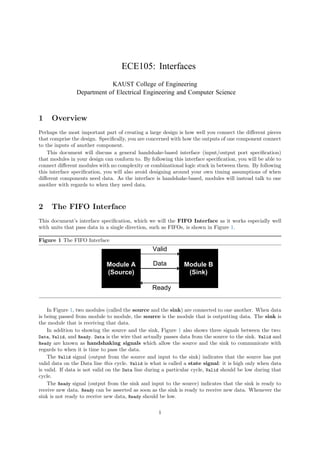
  • 1. Figure 1 The FIFO Interface Valid Ready Data Module A (Source) Module B (Sink) In Figure 1, two modules (called the source and the sink) are connected to one another. When data is being passed from module to module, the source is the module that is outputting data. The sink is the module that is receiving that data. In addition to showing the source and the sink, Figure 1 also shows three signals between the two: Data, Valid, and Ready. Data is the wire that actually passes data from the source to the sink. Valid and Ready are known as handshaking signals which allow the source and the sink to communicate with regards to when it is time to pass the data. The Valid signal (output from the source and input to the sink) indicates that the source has put valid data on the Data line this cycle. Valid is what is called a state signal: it is high only when data is valid. If data is not valid on the Data line during a particular cycle, Valid should be low during that cycle. The Ready signal (output from the sink and input to the source) indicates that the sink is ready to receive new data. Ready can be asserted as soon as the sink is ready to receive new data. Whenever the sink is not ready to receive new data, Ready should be low. 1 ECE105: Interfaces KAUST College of Engineering Department of Electrical Engineering and Computer Science 1 Overview Perhaps the most important part of creating a large design is how well you connect the different pieces that comprise the design. Specifically, you are concerned with how the outputs of one component connect to the inputs of another component. This document will discuss a general handshake-based interface (input/output port specification) that modules in your design can conform to. By following this interface specification, you will be able to connect different modules with no complexity or combinational logic stuck in between them. By following this interface specification, you will also avoid designing around your own timing assumptions of when different components need data. As the interface is handshake-based, modules will instead talk to one another with regards to when they need data. 2 The FIFO Interface This document’s interface specification, which we will the FIFO Interface as it works especially well with units that pass data in a single direction, such as FIFOs, is shown in Figure 1.
  • 2. 3 The Handshake and Data Transfer The FIFO Interface handshake ensures that data passes from the source to the sink only when the source has valid data to pass and when the sink is ready to receive that data. In other words, when Valid and Ready are both high, data on Data will be latched into the sink on the next rising edge. This is an important point: since EECS150 is concerned with synchronous design, data will only be transferred at the rising edge. This handshake, and when it passes data, is shown in Figure 2. Figure 2 Data transfer at the rising edge Clock Valid Ready t r a n s f e r This transfer of data happens on every rising edge where Valid and Ready are both asserted. For each rising edge, however, only one piece of data is transferred. For example, if Valid and Ready are both high for two consecutive cycles, we transfer two data words (on consecutive clock cycles; see Figure 3). Note that data transfer only occurs when both Valid and Ready are high. For example, in Figure 4, neither Valid nor Ready are high. Thus, no data is transferred. Likewise in Figure 5 and Figure 6: if only one of the two handshaking signals is high, no data is transferred. Figure 7 shows another example: if the two handshaking signals are both high at some point, but are out of phase, no data is transferred. 4 Advantages of the FIFO Interface The FIFO Interface eliminates timing assumptions in your design and removes intermediate combina- tional logic between modules. Modules that interface with different pieces of hardware must follow the rules laid out by that hard- ware down to the cycle. To keep track of when every piece of data must be sent / every control signal must be asserted, students will often construct external counters that count time to determine when different events should happen. This type of design is crippled by the fact that students are making large timing assumptions about when each of their modules requires data X or control signal Y. Each module doesnt give feedback on these counters: they are either right or wrong, but are not based on the actual state of the module. If a counter gets misaligned, the circuit will fail horribly. By basing data transfer on handshaking, each module that is handling the data has input as to when the data should and can be passed along. After designing each module, you as the student can forget about the timing of that module, and trust that it will keep track of when it is done processing data and when it is ready to receive more data. The second benefit of the FIFO interface is that it provides a 2-wire standard for connecting modules. To connect to modules that follow the FIFO interface, all 2
  • 3. Figure 3 Two data transfers at two consecutive rising edges Clock Valid Ready t r a n s f e r t r a n s f e r Figure 4 Both handshaking signals are low: no data is transferred Clock Valid Ready Figure 5 Valid is high and Ready is low: no data is transferred Clock Valid Ready 3
  • 4. Figure 6 Valid is low and Ready is high: no data is transferred Clock Valid Ready Figure 7 Both handshaking signals are high at some point, but are out of phase: no data is transferred Clock Valid Ready you have to do is connect the Data port from the source to the sink, the Valid port from the source to the sink, and the Ready port from the sink to the source. When students don’t follow this standard, they typically substitute in large and complex messes of combinational logic in between each of their modules to connect them together. If you design by the FIFO interface, and internalize the logic that generates Valid and Ready, when it comes time to connect modules, you can do so by just connecting ports together. Down the road of the project, this will save you many hours of frustration. 5 When to use the FIFO Interface The FIFO Interface coordinates data transfer. Hence, whenever a module you write passes data to another module, that data should have accompanying Valid and Ready signals. For each Data line that you write these handshaking signals for, you eliminate your own timing assumptions about when that data is supposed to be passed from source to sink, and eliminate a potentially nasty bed of combinational logic between the source and sink. Some modules will have more than one Data port. Such modules should have more than one pair of handshaking signals. For example, the standard FIFO, for which this interface is named, takes data in and passes data out again. A typical FIFO is shown in Figure 8. Notice that the FIFO serves as both a source and sink. This is perfectly fine: the FIFO passes and receives data. 4
  • 5. Figure 8 A FIFO functioning as both a source and sink Valid Ready Data Module A (Source) FIFO Sink Source Module B (Sink) Valid Ready Data 6 A Danger: Combinational Loops When you design using the FIFO Interface, you must be sure that the Valid and Ready signals are not combinationally linked at either end. In other words, you should not be able to trace a path from: 1. The output of the Valid signal (in the source) 2. Through the combinational logic that generates the Ready signal (in the sink) 3. Back to the combinational logic that generates the Valid signal (again, in the source) and visa versa when tracing a path starting at the Ready signal. This path is illustrated in Figure 9. Figure 9 A combinational loop: avoid this at all costs Combinational Logic Combinational Logic Valid Source Ready Sink If you don’t heed this advice, your design will contain a combinational loop. Treat combinational loops as you would latches: if you have one in your design, your circuit will fail miserably. Rev. Name Date Description A Wrote new document; based on Greg Gibeling’s publications on the FIFO Interface 5 Ahmed Abdelazeem 11/20/23